Embed Size (px)
Citation preview
Residential Exterior Wall Superinsulation Retrofit Details and Analysis Conference Paper - 1012 15 December 2010 (rev. May 2011) Kohta Ueno Abstract:
The issues of climate change, energy security, and economics are all strong drivers for improving energy efficiency levels in a variety of sectors. In residential construction, although some inroads have been made in new houses, the stock of existing housing represents a huge opportunity for energy retrofits. The vanguard of these efforts has been pushing toward retrofitting very high insulation levels (i.e., “superinsulation,” or “deep energy retrofits”).
Several cold-climate residential retrofit projects have been completed using an exterior insulation approach on light-frame above-grade walls. This type of retrofit is a reasonable step if a recladding of the building is already being done for aesthetic or ongoing maintenance reasons. The methods demonstrated here result in walls with insulation levels in the R-35 to R-40 range.
This paper presents many of the lessons learned from these experiences, including overall enclosure strategies, such as air barriers, drainage planes, and moisture control. Several case-specific solutions to particular problems are described, including exterior air barrier approaches, wall sill replacement, and several approaches dealing with window penetrations. In addition, detailing recommendations and economic analysis of these measures are presented. Hygrothermal simulations were run to evaluate the changes in sensitivity to moisture intrusion due to these retrofit measures.
building science.com © 2010 Building Science Press All rights of reproduction in any form reserved.
Residential Exterior Wall Superinsulation Retrofit Details and Analysis
Kohta UenoAssociate Member ASHRAE
ABSTRACT
The issues of climate change, energy security, and economics are all strong drivers for improving energy efficiency levelsin a variety of sectors. In residential construction, although some inroads have been made in new houses, the stock of existinghousing represents a huge opportunity for energy retrofits. The vanguard of these efforts has been pushing toward retrofittingvery high insulation levels (i.e., “superinsulation,” or “deep energy retrofits”).
Several cold-climate residential retrofit projects have been completed using an exterior insulation approach on light-frameabove-grade walls. This type of retrofit is a reasonable step if a recladding of the building is already being done for aestheticor ongoing maintenance reasons. The methods demonstrated here result in walls with insulation levels in the R-35 to R-40 range.
This paper presents many of the lessons learned from these experiences, including overall enclosure strategies, such as airbarriers, drainage planes, and moisture control. Several case-specific solutions to particular problems are described, includingexterior air barrier approaches, wall sill replacement, and several approaches dealing with window penetrations. In addition,detailing recommendations and economic analysis of these measures are presented. Hygrothermal simulations were run to eval-uate the changes in sensitivity to moisture intrusion due to these retrofit measures.
INTRODUCTION
The issues of climate change, energy security, andeconomics are all strong drivers for improving energy effi-ciency levels in a variety of sectors. The residential andcommercial building sectors consumed roughly 40% of theprimary energy used in the United States in 2008; this can befurther subdivided into the residential (21%) and commercial(18%) sectors (DOE/EIA 2009). In residential construction,although some inroads have been made in new houses, thestock of existing housing represents a huge opportunity forenergy retrofits. For instance, Gitt (2009) notes that of theexisting stock of 120 million housing units, 70% of them werebuilt before any energy codes were enacted. Although theeffectiveness or ineffectiveness of various energy codes can bedebated, it is reasonable to assume a general trend of increas-ing energy efficiency with the presence of (and/or more strin-gent) energy codes.
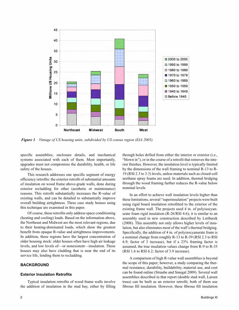
The nationwide distribution of housing stock bygeographic census region and age is shown in Figure 1, basedon US Energy Information Administration (EIA 2005) data. Itdemonstrates trends noted by others (Lutz 2004): for instance,much of the oldest housing stock is concentrated in the North-east, and since the 1970s, the majority of new construction wasconcentrated in the South and West regions.
Given the body of older, less-efficient housing stock, itappears that there is substantial “low-hanging fruit” for energyefficiency retrofits in existing housing. The current politicalclimate is conducive to the implementation of home energyefficiency improvements, both on state and federal levels.However, energy retrofits have historically proven to be diffi-cult to implement in quantity, due to “regulatory constraints,high costs, and the complexities of reaching a fragmentedmarket” (Gitt 2009). Existing homes are a particular challengebecause of the variety of building types, characteristics, site-
© 2010 ASHRAE.
Kohta Ueno is a senior associate at Building Science Corporation, Somerville, MA, and Waterloo, ON.
specific assemblies, enclosure details, and mechanicalsystems associated with each of them. Most importantly,upgrades must not compromise the durability, health, or lifesafety of the houses.
This research addresses one specific segment of energyefficiency retrofits: the exterior retrofit of substantial amountsof insulation on wood frame above-grade walls, done duringexterior recladding for other (aesthetic or maintenance)reasons. This retrofit substantially increases the R-value ofexisting walls, and can be detailed to substantially improveoverall building airtightness. Three case study houses usingthis technique are examined in this paper.
Of course, these retrofits only address space conditioning(heating and cooling) loads. Based on the information above,the Northeast and Midwest are the most relevant regions, dueto their heating-dominated loads, which show the greatestbenefit from opaque R-value and airtightness improvements.In addition, these regions have the largest concentration ofolder housing stock: older houses often have high air leakagelevels, and low levels of—or nonexistent—insulation. Thesehouses may also have cladding that is near the end of itsservice life, lending them to recladding.
BACKGROUND
Exterior Insulation Retrofits
Typical insulation retrofits of wood frame walls involvethe addition of insulation in the stud bay, either by filling
through holes drilled from either the interior or exterior (i.e.,“blown in”), or in the course of a retrofit that removes the inte-rior finishes. However, the insulation level is typically limitedby the dimensions of the wall framing to nominal R-13 to R-19 (RSI 2.3 to 3.3) levels, unless materials such as closed-cellurethane spray foams are used. In addition, thermal bridgingthrough the wood framing further reduces the R-value belownominal levels.
In an effort to achieve wall insulation levels higher thanthese limitations, several “superinsulation” projects were builtusing rigid board insulation retrofitted to the exterior of theexisting frame wall. The projects used 4 in. of polyisocyan-urate foam rigid insulation (R-26/RSI 4.6); it is similar to anassembly used in new construction described by Lstiburek(2008). This assembly not only allows higher levels of insu-lation, but also eliminates most of the wall’s thermal bridging.Specifically, the addition of 4 in. of polyisocyanurate foam isa nominal change from roughly R-13 to R-39 (RSI 2.3 to RSI6.9; factor of 3 increase), but if a 23% framing factor isassumed, the true insulation values change from R-9 to R-35(RSI 1.6 to RSI 6.2; factor of 3.9 increase).
A comparison of high R-value wall assemblies is beyondthe scope of this paper; however, a study comparing the ther-mal resistance, durability, buildability, material use, and costcan be found online (Straube and Smegal 2009). Several wallassemblies described in that report (double stud wall, Larsentruss) can be built as an exterior retrofit; both of them usefibrous fill insulation. However, these fibrous fill insulation
Figure 1 Vintage of US housing units, subdivided by US census region (EIA 2005).
2 Buildings XI
walls are sensitive to wintertime outward moisture movementfrom interior sources, either by vapor flow or airflow, with thelatter being of greater importance. As a result, to ensure dura-bility, these walls depend upon the workmanship of the airbarrier and (to a lesser extent) the vapor barrier. The coldtemperature of the exterior wall sheathing (due to the insula-tion levels/reduction in heat flux) results in substantial periodswhen there is wintertime condensation risk at that surface. Incontrast, the retrofit described here places roughly 2/3 of thethermal resistance outboard of the condensing surface (inte-rior face of the existing sheathing boards). This raises thewintertime condensing surface temperature, and substantiallyreduces the risk of interstitial condensation. Therefore, theassembly described here has some notable durability advan-tages. In addition, this assembly addresses thermal bridging atthe rim joist, which is often a weakness in double stud walls.
In terms of airflow control, it is recommended that theprimary air barrier in a cold climate be located on the interior,to avoid exfiltration of moisture-laden air and resulting inter-stitial condensation (Lstiburek 2006). In an exterior retrofit,however, the air barrier is typically retrofitted outboard of theexisting structure, which raises some durability questions. Inthis case, though, the air barrier is located 1/3 of the waythrough the thickness of the assembly (from the interior):again, the high insulation value outboard of the air barriergreatly reduces the condensation risks of this assembly.
One final question revolves around the choice of an exte-rior retrofit, as opposed to an interior (“gut”) retrofit. Insulat-ing wall assemblies beyond cavity fill levels requires thedisruption of either the interior or exterior fabric; the choice isa value judgment that must be made on a case-by-case basis.One of these surfaces may have greater or less aesthetic orhistorical significance. However, there are some arguments tobe made for an exterior retrofit. For one, the interior is stillhabitable during this retrofit; in fact, two of the following casestudies were conducted on occupied houses. Increasing thethickness of the wall at the interior results in a loss of habitablesquare footage. In exterior retrofits where the existing clad-ding is first removed, it provides an opportunity to inspect thecondition of the building, including finding and repairingpreviously undetected leakage or moisture damage. Morelimited insulation techniques might not find these issues,resulting in long-term moisture damage consequences, whichwould be exacerbated by the reduction in heat flow (and thusdrying potential) due to insulation retrofits. The exterior insu-lation technique described here places non-moisture-sensitiveinsulation outboard of the existing structure, thus providing alayer of protection
Finally, applying insulation on the exterior can success-fully handle details such as stairwells on exterior walls andintersecting tee walls, which have limited options when insu-lating from the interior.
Previous Work
The authors do not mean to imply that the use of substan-tial amounts of thermal insulation outboard of the structure isan innovative technique by any means; this method has a longhistory in the building science community. The basic conceptswere spelled out by Hutcheon (1964); this method involves theuse of a vapor-, air-, and water-control layer exterior to thestructure (e.g., bituminous adhered membrane), with insula-tion outboard of this layer, and the finish cladding exterior tothe insulation. These concepts were also described by Lstibu-rek (2007); some implementations have included the pressure-equalized rain screen insulated structure technique(PERSIST) construction method (Baker and Makepeace2001), residential exterior membrane outside insulation tech-nique (REMOTE) by the Cold Climate Housing ResearchCenter (Benesh 2009), and the Building America/HydaburgTribe house (Lstiburek 2009). The challenges associated withexterior insulation, such as cladding attachment through thicknonstructural insulation, and the attachment of noncondi-tioned portions of the outer shell (e.g., decks and porch roofs)were also encountered in the projects described here.However, it should be noted that the techniques used in theseprojects are not completely analogous to this previous work.
The exterior insulation concept is not limited to newconstruction; some similar techniques were applied in a retro-fit situation by Orr and Dumont (1987), in their so-called“chainsaw retrofit.” This project was the exterior insulationretrofit of a circa 1970 stucco-clad bungalow; one key pointwas that the entire exterior enclosure was wrapped with a 6 mil(0.15 mm) polyethylene vapor and air barrier. In order to avoidwrapping the overhanging roof eave, the entire detail was cutoff flush (thus the “chainsaw retrofit” name), rendering theshape of the house a relatively simple solid with planar faces.An exterior wood frame was constructed outboard of the wallsand roof, fiberglass insulation was applied in the cavity formedby the frame, and exterior sheathing and cladding wereapplied. High levels of exterior insulation were installed: R-39(RSI 6.8) roof, and R-40 (RSI 7.0) walls. The researchersmeasured a substantial increase in airtightness, going from2.95 ACH 50 (air changes per hour at 50 Pa test pressure) to0.29 ACH 50. Measured results indicated a substantial reduc-tion in heating load (factor of 2.4 reduction).
Researchers at Oak Ridge National Laboratory (Stovall etal. 2007) examined some exterior wall insulation and airtight-ness retrofit options. They first took laboratory thermal perfor-mance (“hot box”) measurements of heat flow reductions intest walls (both opaque wall only, and with an installedwindow). The wall upgrades included options commonly usedin retrofit residing, including 3/8 in. (9.5 mm) and 1/2 in.(12 mm) extruded polystyrene (XPS) foam, 1 in. (25 mm) offoil-faced polyisocyanurate, and expanded polystyrene (EPS)contoured to fit the profile of hollow vinyl siding. Theresearchers also performed laboratory measurements of the airleakage characteristics of several window-to-wall air sealingmethods. They combined this information with whole-house
Buildings XI 3
energy simulations, to estimate energy savings associated withthese retrofits for three house models in ten climate zones. Thepredicted heating and cooling energy cost savings showedexpected patterns of greater savings with increasing R-value;for reference, the 1 in. (25 mm) foil-faced polyisocyanurateshowed typical savings in the 10–15% range when appliedover an existing insulated frame wall. It is interesting to notethat these levels of savings were even seen in cities typicallyassociated with greater cooling loads, such as Phoenix, AZ,Atlanta, GA, and Bakersfield, CA. The one exception wasMiami, FL, which only showed 5% savings with the describedassembly. Of course, it must be remember that although manycities showed the same percentage (10–15%) savings, theabsolute magnitude of savings (and thus associated energypaybacks) will vary with local heating and cooling loads.
CASE STUDIES
Three residential renovation projects were completedusing exterior foam insulating sheathing installed duringrecladding; the projects and their results are described in thefollowing case studies. All of these projects include the retrofitof high levels of exterior wall insulation (~R-26, or RSI 4.6),which results in total nominal insulation levels in the R-35 toR-40 (RSI 6.2–7.0) range. The projects had programmaticgoals of achieving high overall insulation levels (i.e., “super-insulation” or “deep energy retrofits”). The wall retrofit wasonly one of many measures undertaken in these energy retro-
fits: other upgrades included roof insulation, foundation insu-lation, window replacement, and mechanical equipmentreplacement.
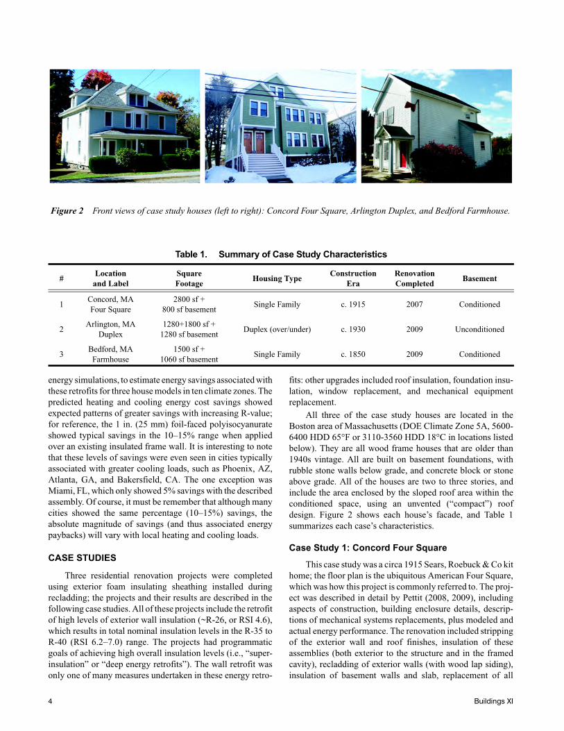
All three of the case study houses are located in theBoston area of Massachusetts (DOE Climate Zone 5A, 5600-6400 HDD 65°F or 3110-3560 HDD 18°C in locations listedbelow). They are all wood frame houses that are older than1940s vintage. All are built on basement foundations, withrubble stone walls below grade, and concrete block or stoneabove grade. All of the houses are two to three stories, andinclude the area enclosed by the sloped roof area within theconditioned space, using an unvented (“compact”) roofdesign. Figure 2 shows each house’s facade, and Table 1summarizes each case’s characteristics.
Case Study 1: Concord Four Square
This case study was a circa 1915 Sears, Roebuck & Co kithome; the floor plan is the ubiquitous American Four Square,which was how this project is commonly referred to. The proj-ect was described in detail by Pettit (2008, 2009), includingaspects of construction, building enclosure details, descrip-tions of mechanical systems replacements, plus modeled andactual energy performance. The renovation included strippingof the exterior wall and roof finishes, insulation of theseassemblies (both exterior to the structure and in the framedcavity), recladding of exterior walls (with wood lap siding),insulation of basement walls and slab, replacement of all
Table 1. Summary of Case Study Characteristics
#Location
and LabelSquareFootage
Housing TypeConstruction
EraRenovation Completed
Basement
1Concord, MAFour Square
2800 sf + 800 sf basement
Single Family c. 1915 2007 Conditioned
2Arlington, MA
Duplex1280+1800 sf +
1280 sf basementDuplex (over/under) c. 1930 2009 Unconditioned
3Bedford, MAFarmhouse
1500 sf + 1060 sf basement
Single Family c. 1850 2009 Conditioned
Figure 2 Front views of case study houses (left to right): Concord Four Square, Arlington Duplex, and Bedford Farmhouse.
4 Buildings XI
windows, and complete replacement of the mechanicalsystem.
It should be noted that the roof design did not lend itselfto a chainsaw-style retrofit (removing the overhanging eavesto simplify air sealing details): the bearing point of the roofrafters is cantilevered outboard of exterior stud frame wall,attached to the horizontal ceiling joist. This would haverequired substantial structural work to remove the eaves, inorder to simplify the air sealing detail.
Since this project was completed from the exterior, all ofthe interior finishes were left intact; there were many featuresworth preserving, including maple floors, interior wood trim,and interior lath and plaster in good condition. Some preser-vationists consider deep energy retrofits to be a threat tohistoric houses, claiming that these measures are “strippingaway much of the charm, character, and historical value thatattract people to these modest older houses in the first place”(Zimmerman 2009). However, this house can be considered anexemplary case of an architecturally sensitive energy retrofitthat preserves and celebrates the original character of thehouse, replicating or mimicking the original exterior details.
Case Study 2: Arlington Duplex
This case study was a circa 1930 duplex; the two units arearranged in an over/under manner, with the first floor compris-ing one unit, and the second and third (attic) floors comprisingthe second unit. The project was prompted by a unit ownerwho had an interest in deep energy retrofits, and obtainedfunding and material contributions from a variety of sources.The project was partly funded by the Massachusetts Depart-ment of Energy Resources. The specifics of the construction ofthis project are covered by Joyce (2009), which includessection drawings, construction sequence, and detailed photo-graphs.
The renovation included stripping the exterior wall androof finishes, insulation of these assemblies (both exterior tothe structure and in the framed cavity), recladding exteriorwalls with cellular PVC lap siding, and replacement of allwindows. The choice of measures was a matter of energy andeconomic analysis, as well as discussions with the home-owner, who wanted to limit the budget and associated scope ofwork.
For instance, the heating plants (single-pipe steam boil-ers; natural draft combustion) were retained, as single-pipesteam does not lend itself to a simple replacement withhydronic heating; it should be noted that steam systems haveintrinsic efficiency limitations. The author’s recommendationto the client was to include the basement within the condi-tioned enclosure (by insulating and air-sealing the basementwalls), in order to recapture distribution losses from the boilersystems, simplify air barrier detailing, and include greaterusable volume within the conditioned space. However, thiswould require the addition of combustion safety measures tothe existing equipment (i.e., makeup air kits), since the unitsare being brought within the conditioned space. The home-
owner instead chose to isolate the basement from the firstfloor, removing the basement ceiling finish and using low-density spray foam to insulate and air-seal the joist bay cavitiesfrom below.
Case Study 3: Bedford Farmhouse
The final case study was a circa 1850 single-family farm-house, which was being renovated by Habitat for Humanity ofGreater Lowell for use as energy-efficient affordable housing.Technical guidance for the project was funded by the Depart-ment of Energy’s Building America Program. This propertywas unconditioned and empty prior to this renovation.
The renovation included demolition of poorlyconstructed additions, stripping the exterior wall and rooffinishes, insulation of these assemblies (both exterior to thestructure and in the framed cavity), recladding exterior wallswith vinyl siding, insulation of basement walls and slab,replacement of all windows, and complete replacement of themechanical system. Although interior finishes were originallyleft intact, during construction, a decision was made toperform a gut demolition, to remove the need for lead paintremoval/encapsulation of the existing interior trim. Construc-tion was completed by Habitat for Humanity volunteers andstudents from a local technical high school.
WALL ASSEMBLY CONSTRUCTION SPECIFICS
Wall Assembly Overview
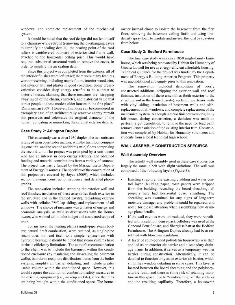
The retrofit wall assembly used in these case studies waslargely the same, albeit with slight variations. The wall wascomposed of the following layers (Figure 3):
• Existing structure: the existing cladding and water con-trol layer (building paper, rosin paper) were strippedfrom the building, revealing the board sheathing; allprojects here had horizontal board sheathing. Thesheathing was examined for any signs of long-termmoisture damage; any problems could be repaired, andnoted for closer attention when assembling new drain-age plane details.
• If the wall cavities were uninsulated, they were retrofit-ted with insulation; dense-pack cellulose was used at theConcord Four Square, and fiberglass batt at the BedfordFarmhouse. The Arlington Duplex already had been ret-rofitted with blown-in insulation.
• A layer of spun-bonded polyolefin housewrap was thenapplied as an exterior air barrier and a secondary drain-age plane. In addition, it serves as a temporary weatherbarrier during construction. Alternatively, it can bedetailed to function only as an exterior air barrier, whichsimplifies window detailing in some cases. This layer islocated between the board sheathing and the polyisocy-anurate foam, and there is some risk of retaining mois-ture in this space, due to “sandwiching” of flat surfacesand the resulting capillarity. Therefore, a housewrap
Buildings XI 5
with corrugations to provide drainage was chosen. Inorder for this layer to be effective as an air barrier, con-nection details were required: for instance, at the foun-dation to above-grade wall connection, the housewrapwas caulked to the lowest piece of board sheathing.
• At the Bedford Farmhouse, after the housewrap wasapplied, the design team noted during a site visit that theinstallation was not conducive to use as an air barrier.Problems included tenting at inside corners, incompletecoverage, and a piecemeal application; it would havebasically required a reapplication of this layer to have afunctional air barrier. As a result, the team decided to nolonger use the housewrap layer, instead providingdetails to use the outer layer of polyisocyanurate at theair barrier, connecting it in a continuous manner. Theresults of this alternate approach are covered in the CaseStudy Lessons Learned section.
• Two layers of 2 in. (51 mm) foil-faced polyisocyanuratewere applied, with staggered seams between layers, toavoid a “straight-through” path for air or water penetra-tion. The seams of the outer layer of foam were tapedwith adhesive tape, to provide the primary drainageplane/water control layer, as well as a secondary layer ofairflow resistance. Foil-faced polyisocyanurate was cho-sen because of its high per-inch insulating value, as wellas the ability to tape the foil surface (as opposed toexpanded polystyrene or fiberglass-faced polyisocyan-
urate; however, taped seams are common with extrudedpolystyrene). Typically, the layers of foam were tempo-rarily held in place with oversized (~3 in. diameter)metal washers, commonly used in commercial roofing.
• Vertical wood 1 × 3 strapping (0.75 in. × 2.5 in. or 19mm × 64 mm) was applied outboard of the foam at thestud locations, using self-drilling heavy-duty flat-headscrew fasteners with sufficient length to provide attach-ment to the stud. This strapping serves several purposes.First, it acts as an oversized washer, holding the foam tothe surface of the house. Second, it acts as a substratefor cladding attachment. Third, and most importantly,the ¾ in. (19 mm) space created by the strapping resultsin a drainage and ventilation cavity. Drained wall sys-tems are widely recommended as the best strategy forcontrolling rain penetration. (Ritchie 1961; CMHC1999; Lstiburek 2006); wall ventilation has been dem-onstrated to add significant drying capacity to claddingassemblies (Straube et al. 2004; Straube and Burnett2005). Both of these increase the durability of theassembly, and greatly limit the amount of rain penetra-tion to the secondary drainage plane (housewrap).
Wall Assembly Details
Two aspects of this assembly are worth covering in moredetail: the strapping attachment over rigid foam sheathing, andthe window plane location.
Figure 3 Isometric view of wall retrofit assembly, showing assembly components.
6 Buildings XI
Strapping Attachment. A question commonly asked inthe field concerns the strength and durability of strappingattached through rigid plastic foam insulation, and the possi-bility of sagging of the cladding or crushing of the foam. Theseconcerns, while understandable, have little validity; this isborne out by a long history (20+ years) of large numbers ofsimilar assemblies in the field with no evidence of systematicproblems.
The problem can be broken down into several compo-nents. Two are the loads perpendicular to the wall: the pull-outand compression loads, which are associated with wind loads.The pull-out strength can be calculated from the fastenerstrength, penetration depth, and placement schedule asrequired for a particular loading. Allowable compressive loadscan be calculated based on the compressive strength of therigid foam sheathing layer. Representative publishedcompressive strengths are 10–15 psi (69–103 kPa) forexpanded polystyrene (EPS), 15–30 psi (103–207 kPa) forextruded polystyrene (XPS), and 25 psi (172 kPa) for polyiso-cyanurate (at 10% deformation or yield). With 1 × 3 (2.5 in.,or 64 mm) strapping at 24 in. (610 mm) on center (o.c.), theloads that could be transferred through the foam are 225 and375 pounds per square foot (psf) (10.7 and 18.0 kPa), respec-tively, for XPS (lower value) and polyisocyanurate. For refer-ence, the design wind pressures mentioned in the codes are inthe range of 20 to 30 psf (ICC 2009), an order of magnitudelower than the allowable compressive loads.
The remaining load is the vertical load, due to the deadweight of the cladding. This load does not act on the screw asa cantilever beam extending horizontally from the backupwall, which might be considered a reasonable first approxi-mation. Instead, in reality, the strapping, foam, and screws acttogether as a simple truss: the screw acts in tension, and a
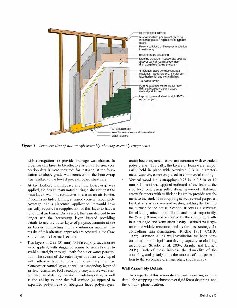
compression strut forms through the strapping and the foam.This calculation is not performed here; however, laboratorymock up tests were conducted (Figure 4), demonstrating avery high safety factor.
The test wall was a 4 ft × 8 ft (1220 mm × 2440 mm) panel,with 2 in. (51 mm) XPS on a 24 in. (610 mm) o.c. wood studframe, rigidly attached to the block wall. The foam sheathingwas held in place with 1 × 3 strapping, fastened using 4 in. (102mm) No. 10 screws spaced at 12 in. (305 mm). A steel 1 in. ×1 in. (25 mm × 25 mm) channel was fastened across the twostrapping pieces, and a cable was attached to the channel at thecenterline of the panel. A dial indicator was set up so that itwould measure the deflection of the channel near the strapping(so as to minimize the effect of any deflection of the channel).At a 20 lb (9.1 kg) loading, which is equivalent to a claddingweight of 0.6 psf (30.0 Pa), deflection was under measurementlimits (<0.001 in., or 0.03 mm). At a loading of roughly 250lb (113 kg), the displacement was under 0.003 in. (0.08 mm);this is equivalent to a cladding load of 7.8 psf (370 Pa). Forreference, typical cladding loads are 0.5 psf (24 Pa) for vinylsiding, 1–2 psf (48–96 Pa) for wood lap siding, 2–3 psf (96–144 Pa) for fiber cement lap siding, and 8–10 psf (380–480 Pa)for cement stucco.
Lastly, it should be noted that extruded polystyrene andpolyisocyanurate are viscoelastic materials, and will experi-ence creep over sustained loadings. One manufacturer recom-mends additional design safety factors to compensate for thisproperty, with 3–1 for static loads, and 5–1 for dynamic loads(Dow 2007). Given the relationships between loadings andcapacity shown above, these loads are well below levels wherecreep is a consideration.
Window Plane Location. Construction of walls withthick exterior rigid foam results in a thick wall; therefore,
Figure 4 Laboratory mock up testing of deflection with load; 2 in. (51 mm) XPS foam and 1 × 3 strapping, 24 in. (610 mm) o.c.
Buildings XI 7
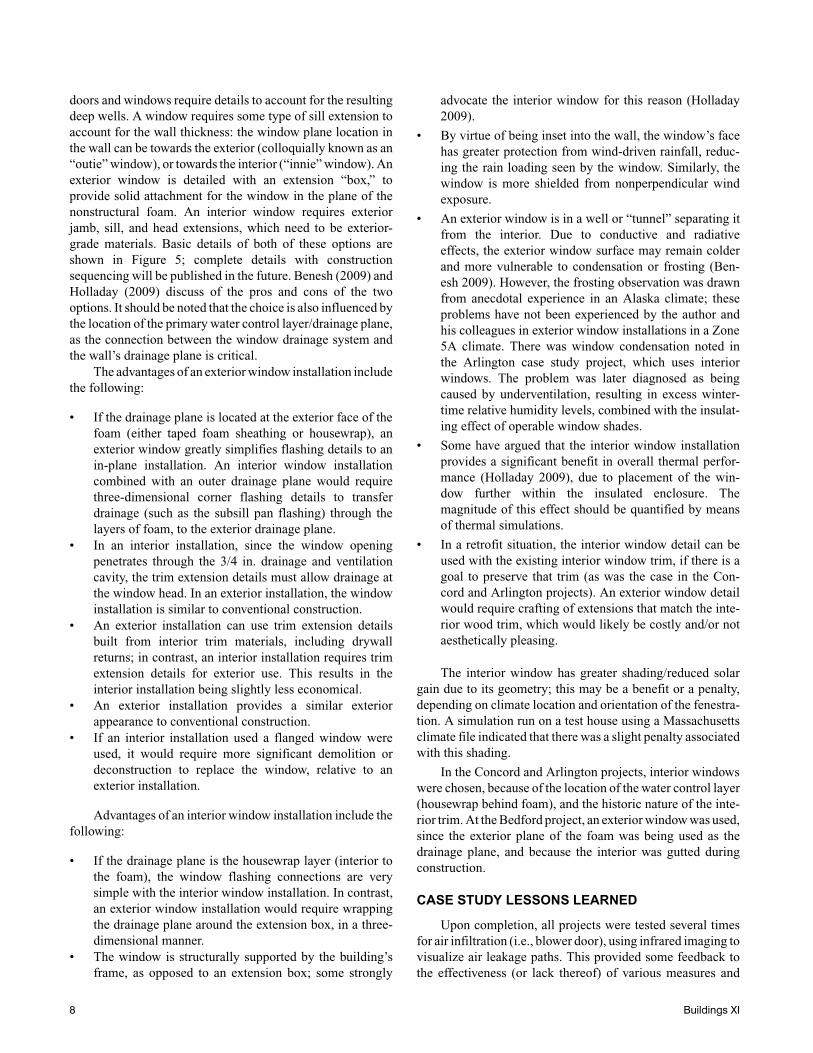
doors and windows require details to account for the resultingdeep wells. A window requires some type of sill extension toaccount for the wall thickness: the window plane location inthe wall can be towards the exterior (colloquially known as an“outie” window), or towards the interior (“innie” window). Anexterior window is detailed with an extension “box,” toprovide solid attachment for the window in the plane of thenonstructural foam. An interior window requires exteriorjamb, sill, and head extensions, which need to be exterior-grade materials. Basic details of both of these options areshown in Figure 5; complete details with constructionsequencing will be published in the future. Benesh (2009) andHolladay (2009) discuss of the pros and cons of the twooptions. It should be noted that the choice is also influenced bythe location of the primary water control layer/drainage plane,as the connection between the window drainage system andthe wall’s drainage plane is critical.
The advantages of an exterior window installation includethe following:
• If the drainage plane is located at the exterior face of thefoam (either taped foam sheathing or housewrap), anexterior window greatly simplifies flashing details to anin-plane installation. An interior window installationcombined with an outer drainage plane would requirethree-dimensional corner flashing details to transferdrainage (such as the subsill pan flashing) through thelayers of foam, to the exterior drainage plane.
• In an interior installation, since the window openingpenetrates through the 3/4 in. drainage and ventilationcavity, the trim extension details must allow drainage atthe window head. In an exterior installation, the windowinstallation is similar to conventional construction.
• An exterior installation can use trim extension detailsbuilt from interior trim materials, including drywallreturns; in contrast, an interior installation requires trimextension details for exterior use. This results in theinterior installation being slightly less economical.
• An exterior installation provides a similar exteriorappearance to conventional construction.
• If an interior installation used a flanged window wereused, it would require more significant demolition ordeconstruction to replace the window, relative to anexterior installation.
Advantages of an interior window installation include thefollowing:
• If the drainage plane is the housewrap layer (interior tothe foam), the window flashing connections are verysimple with the interior window installation. In contrast,an exterior window installation would require wrappingthe drainage plane around the extension box, in a three-dimensional manner.
• The window is structurally supported by the building’sframe, as opposed to an extension box; some strongly
advocate the interior window for this reason (Holladay2009).
• By virtue of being inset into the wall, the window’s facehas greater protection from wind-driven rainfall, reduc-ing the rain loading seen by the window. Similarly, thewindow is more shielded from nonperpendicular windexposure.
• An exterior window is in a well or “tunnel” separating itfrom the interior. Due to conductive and radiativeeffects, the exterior window surface may remain colderand more vulnerable to condensation or frosting (Ben-esh 2009). However, the frosting observation was drawnfrom anecdotal experience in an Alaska climate; theseproblems have not been experienced by the author andhis colleagues in exterior window installations in a Zone5A climate. There was window condensation noted inthe Arlington case study project, which uses interiorwindows. The problem was later diagnosed as beingcaused by underventilation, resulting in excess winter-time relative humidity levels, combined with the insulat-ing effect of operable window shades.
• Some have argued that the interior window installationprovides a significant benefit in overall thermal perfor-mance (Holladay 2009), due to placement of the win-dow further within the insulated enclosure. Themagnitude of this effect should be quantified by meansof thermal simulations.
• In a retrofit situation, the interior window detail can beused with the existing interior window trim, if there is agoal to preserve that trim (as was the case in the Con-cord and Arlington projects). An exterior window detailwould require crafting of extensions that match the inte-rior wood trim, which would likely be costly and/or notaesthetically pleasing.
The interior window has greater shading/reduced solargain due to its geometry; this may be a benefit or a penalty,depending on climate location and orientation of the fenestra-tion. A simulation run on a test house using a Massachusettsclimate file indicated that there was a slight penalty associatedwith this shading.
In the Concord and Arlington projects, interior windowswere chosen, because of the location of the water control layer(housewrap behind foam), and the historic nature of the inte-rior trim. At the Bedford project, an exterior window was used,since the exterior plane of the foam was being used as thedrainage plane, and because the interior was gutted duringconstruction.
CASE STUDY LESSONS LEARNED
Upon completion, all projects were tested several timesfor air infiltration (i.e., blower door), using infrared imaging tovisualize air leakage paths. This provided some feedback tothe effectiveness (or lack thereof) of various measures and
8 Buildings XI
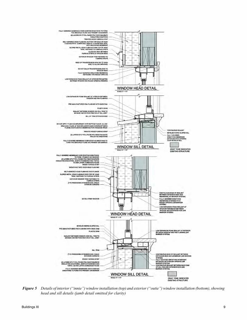
Figure 5 Details of interior (“innie”) window installation (top) and exterior (“outie”) window installation (bottom), showinghead and sill details (jamb detail omitted for clarity)
Buildings XI 9
details. The overall results from the Bedford project arecovered in specific detail.
Air Barrier Performance
The air infiltration test results shown here represent theoverall leakage for the house; therefore, it is difficult toconsider these figures to be a perfect representation of theeffectiveness of any given technique or detail, especially giventhe small sample size. Instead, the results show the combinedeffect of the materials, details, workmanship, and house-specific conditions in a given case study. Direct measurementof details under laboratory conditions would be better suitedfor testing specific techniques and details.
During the planning of these projects, it was hoped thatthe layering present in the assembly (housewrap, and multiplelayers of rigid foam) would result in excellent air barrierperformance. For instance, Straube and Burnett (2005) pointout that if secondary layers are airtight, they can contributegreatly to overall airtightness, instead of relying on a singlenominal air barrier layer.
The resulting performance is shown in Table 2. Tableheadings include conditioned enclosure surface area (insquare feet, including below-grade surface area), the infiltra-tion test result (in CFM 50, or cubic feet per minute at 50 Patest pressure), ACH 50 (air changes per hour at 50 Pa), EqLA(equivalent leakage area, in square inches) (Canadian GeneralStandards Board [CGSB] 1986), calculated at a 10 Pa pressuredifferential), and EqLA per 100 ft2 of enclosure area. A testprior to renovation was performed on one of these three proj-ects (the Arlington Duplex); that test result was 15.6 ACH 50.The other houses were not tested before renovation, but giventheir vintage, leakage in the 10–15 ACH 50 range is plausible.It should be noted that since the Arlington project was aduplex, both pre- and post-renovation tests were done usingtwo blower doors, in a “nulling” test (neutral pressure betweenunits), to eliminate inter-unit leakage and only measure leak-age to the exterior.
Overall, the results were good for the Concord FourSquare, reasonable for the Arlington Duplex (and a vastimprovement from 15.6 ACH 50), and somewhat disappoint-ing for the Bedford Farmhouse. Several facts should berecalled: the Arlington Duplex does not include the basementwithin the conditioned space, with the air barrier (spray foam)instead used at the basement ceiling. The Bedford Farmhouse
did not have the housewrap layer as an air barrier: instead, theexterior foam layer was detailed as an air barrier.
During infiltration testing (house held at negative pres-sure; typically 20–25 Pa), an infrared camera was used to finddiscrete air leakage points. As a general observation, the fieldof wall typically showed little sign of air leakage, with someexceptions. Some penetrations through the interior walls(electrical receptacles, sill plate, window trim apron) showedsigns of air leakage; however, this method only shows the inte-rior exit point of the air leakage, without revealing thecomplete pathway. However, in other cases, specific air leak-age points could be pinpointed, and some of them were quitesignificant.
• Windows and doors: The air seal at the replacementwindows was somewhat disappointing: all showed signsof air infiltration, and some units showed substantialleakage (i.e., visible with infrared as warm leakageplume from exterior, Concord Four Square). Problemswere expected, given that all windows were sliding dou-ble hung windows, which face intrinsic problems due totheir sliding air seal, and the change in the plane of theweatherstripping (meeting rail). In addition, some doorshad demonstrably poor air seals (including particularlyleaky basement doors), which is a relatively commonproblem and not unique to energy retrofits.
• Window/wall connection: In general, the window/wallconnection appeared to be well sealed, with minimalsigns of significant leakage. One exception was a sky-light at the Arlington Duplex, which showed signs ofsignificant leakage behind the interior drywall finish. Inaddition, jets of leakage appeared from the window inte-rior apron trim. Although this could have beenaddressed during window replacement by removing thetrim, it was a balance between air sealing and disruptionof interior finishes/increases in scope of work.
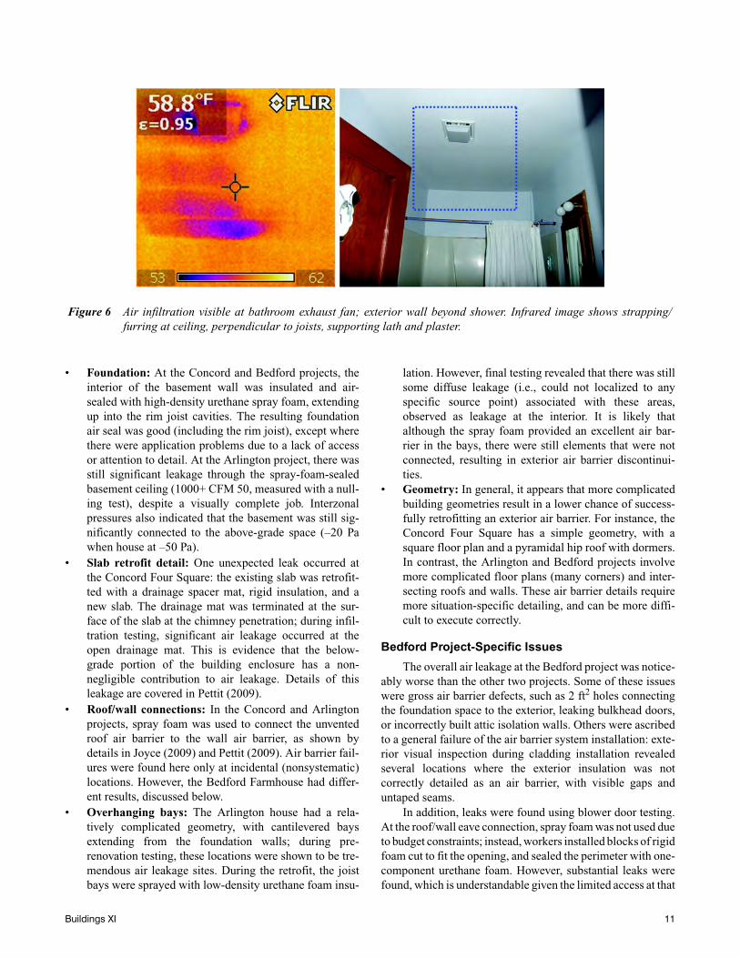
• Mechanical: Several mechanical exhaust fans proved tobe significant leakage locations, including the kitchenrange hood at the Concord Four Square and the bath-room exhausts at the Arlington Duplex, as shown in Fig-ure 6. In addition, leakage bypassing the backdraftdamper is visible. It is not clear whether the leakageoccurs at the exterior penetration, or via leakage of theexhaust duct within the joist cavity.
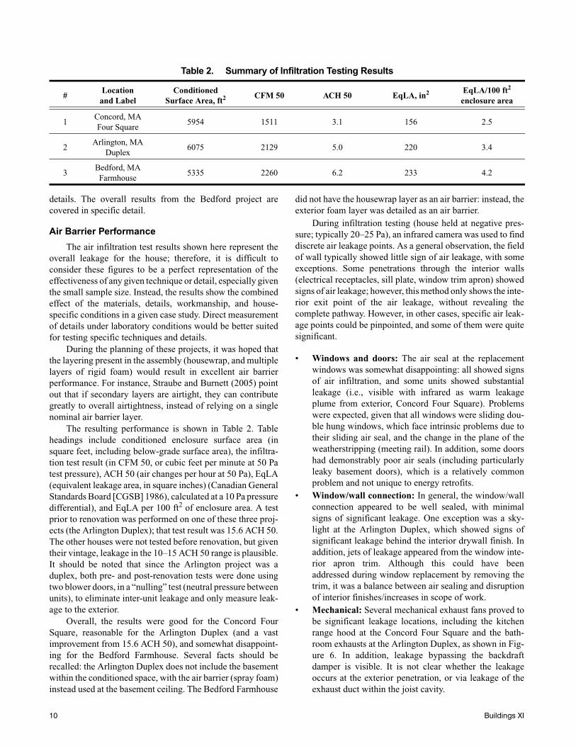
Table 2. Summary of Infiltration Testing Results
#Location
and LabelConditioned
Surface Area, ft2 CFM 50 ACH 50 EqLA, in2 EqLA/100 ft2 enclosure area
1Concord, MAFour Square
5954 1511 3.1 156 2.5
2Arlington, MA
Duplex6075 2129 5.0 220 3.4
3Bedford, MAFarmhouse
5335 2260 6.2 233 4.2
10 Buildings XI
• Foundation: At the Concord and Bedford projects, theinterior of the basement wall was insulated and air-sealed with high-density urethane spray foam, extendingup into the rim joist cavities. The resulting foundationair seal was good (including the rim joist), except wherethere were application problems due to a lack of accessor attention to detail. At the Arlington project, there wasstill significant leakage through the spray-foam-sealedbasement ceiling (1000+ CFM 50, measured with a null-ing test), despite a visually complete job. Interzonalpressures also indicated that the basement was still sig-nificantly connected to the above-grade space (–20 Pawhen house at –50 Pa).
• Slab retrofit detail: One unexpected leak occurred atthe Concord Four Square: the existing slab was retrofit-ted with a drainage spacer mat, rigid insulation, and anew slab. The drainage mat was terminated at the sur-face of the slab at the chimney penetration; during infil-tration testing, significant air leakage occurred at theopen drainage mat. This is evidence that the below-grade portion of the building enclosure has a non-negligible contribution to air leakage. Details of thisleakage are covered in Pettit (2009).
• Roof/wall connections: In the Concord and Arlingtonprojects, spray foam was used to connect the unventedroof air barrier to the wall air barrier, as shown bydetails in Joyce (2009) and Pettit (2009). Air barrier fail-ures were found here only at incidental (nonsystematic)locations. However, the Bedford Farmhouse had differ-ent results, discussed below.
• Overhanging bays: The Arlington house had a rela-tively complicated geometry, with cantilevered baysextending from the foundation walls; during pre-renovation testing, these locations were shown to be tre-mendous air leakage sites. During the retrofit, the joistbays were sprayed with low-density urethane foam insu-
lation. However, final testing revealed that there was stillsome diffuse leakage (i.e., could not localized to anyspecific source point) associated with these areas,observed as leakage at the interior. It is likely thatalthough the spray foam provided an excellent air bar-rier in the bays, there were still elements that were notconnected, resulting in exterior air barrier discontinui-ties.
• Geometry: In general, it appears that more complicatedbuilding geometries result in a lower chance of success-fully retrofitting an exterior air barrier. For instance, theConcord Four Square has a simple geometry, with asquare floor plan and a pyramidal hip roof with dormers.In contrast, the Arlington and Bedford projects involvemore complicated floor plans (many corners) and inter-secting roofs and walls. These air barrier details requiremore situation-specific detailing, and can be more diffi-cult to execute correctly.
Bedford Project-Specific Issues
The overall air leakage at the Bedford project was notice-ably worse than the other two projects. Some of these issueswere gross air barrier defects, such as 2 ft2 holes connectingthe foundation space to the exterior, leaking bulkhead doors,or incorrectly built attic isolation walls. Others were ascribedto a general failure of the air barrier system installation: exte-rior visual inspection during cladding installation revealedseveral locations where the exterior insulation was notcorrectly detailed as an air barrier, with visible gaps anduntaped seams.
In addition, leaks were found using blower door testing.At the roof/wall eave connection, spray foam was not used dueto budget constraints; instead, workers installed blocks of rigidfoam cut to fit the opening, and sealed the perimeter with one-component urethane foam. However, substantial leaks werefound, which is understandable given the limited access at that
Figure 6 Air infiltration visible at bathroom exhaust fan; exterior wall beyond shower. Infrared image shows strapping/furring at ceiling, perpendicular to joists, supporting lath and plaster.
Buildings XI 11
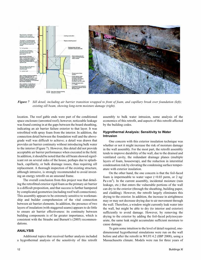
location. The roof gable ends were part of the conditionedspace enclosure (unvented roof); however, noticeable leakagewas found coming in at the gaps between the board sheathing,indicating an air barrier failure exterior to that layer. It wasretrofitted with spray foam from the interior. In addition, theconnection detail between the foundation wall and the above-grade wall was difficult to achieve; a detail was drawn thatprovides air barrier continuity without introducing bulk waterto the interior (Figure 7). However, this detail did not provideacceptable air barrier performance when executed in the field.In addition, it should be noted that the sill beam showed signif-icant rot on several sides of the house, perhaps due to splash-back, capillarity, or bulk drainage issues, thus requiring sillreplacement. A thorough inspection of the existing structure,although intrusive, is strongly recommended to avoid invest-ing an energy retrofit on an unsound frame.
The overall conclusion from this project was that detail-ing the retrofitted exterior rigid foam as the primary air barrieris a difficult proposition, and that success is further hamperedby complicated geometries (including roof/wall connections).This assembly appears to be extremely sensitive to workman-ship and builder comprehension of the vital connectionbetween air barrier elements. In addition, the presence of twolayers of insulation (with staggered seams) appears to do littleto ensure air barrier effectiveness: its continuity betweenbuilding components is of far greater importance, which isconsistent with the Straube and Burnett’s (2005) recommen-dations.
ANALYSIS
Additional topics that received further analysis includeda hygrothermal analysis of the sensitivity of this retrofit
assembly to bulk water intrusion, some analysis of theeconomics of this retrofit, and aspects of this retrofit affectedby the building codes.
Hygrothermal Analysis: Sensitivity to Water Intrusion
One concern with this exterior insulation technique waswhether or not it might increase the risk of moisture damagein the wall assembly. For the most part, the retrofit assemblytends to improve durability of the wall, due to the drained andventilated cavity, the redundant drainage planes (multiplelayers of foam, housewrap), and the reduction in interstitialcondensation risk by elevating the condensing surface temper-ature with exterior insulation.
On the other hand, the one concern is that the foil-facedfoam is impermeable to water vapor (<0.03 perm, or 2 ng/Pa·s·m2). In the current assembly, incidental moisture (rainleakage, etc.) that enters the vulnerable portions of the wallcan dry to the exterior (through the sheathing, building paper,and cladding). However, the retrofit largely eliminates thisdrying to the exterior. In addition, the increase in airtightnessmay or may not decrease drying due to air movement throughthe wall. Therefore, a window might currently leak water intothe wall, but might be able to dry (to interior and exterior)sufficiently to avoid damage. However, by removing thedrying to the exterior by adding the foil-faced polyisocyan-urate, the same leak might accumulate sufficient moisture tocause damage.
To gain some intuition to the level of detail required, one-dimensional hygrothermal simulations were run on the wallbefore and after the retrofit in WUFI 4.2 (IBP 2008), using aMassachusetts climate. Models were run for three years of
Figure 7 Sill detail, including air barrier transition wrapped to front of foam, and capillary break over foundation (left);existing sill beam, showing long-term moisture damage (right).
12 Buildings XI
simulated time, to determine increasing or decreasing mois-ture content patterns. Water was introduced at the board-sheathing-to-insulation interface, and selected as a fraction ofincident driving rainfall on the wall surface.
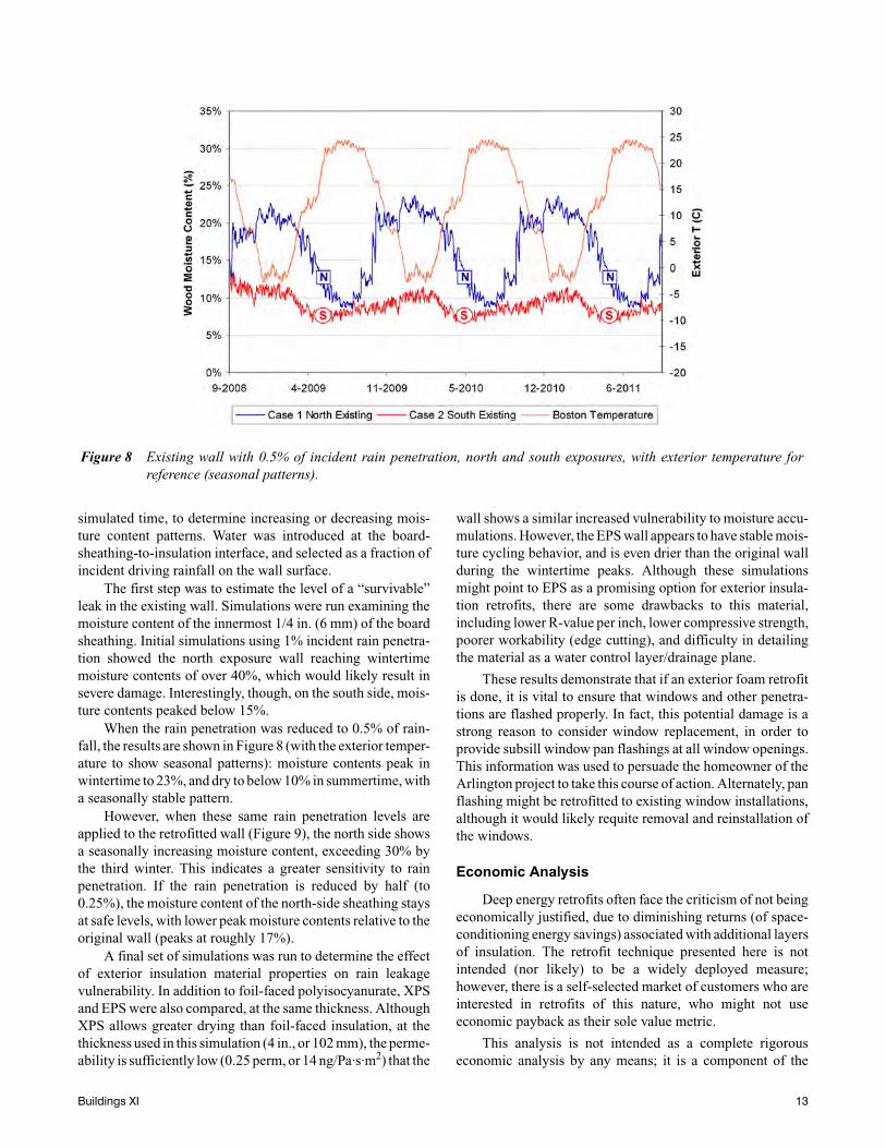
The first step was to estimate the level of a “survivable”leak in the existing wall. Simulations were run examining themoisture content of the innermost 1/4 in. (6 mm) of the boardsheathing. Initial simulations using 1% incident rain penetra-tion showed the north exposure wall reaching wintertimemoisture contents of over 40%, which would likely result insevere damage. Interestingly, though, on the south side, mois-ture contents peaked below 15%.
When the rain penetration was reduced to 0.5% of rain-fall, the results are shown in Figure 8 (with the exterior temper-ature to show seasonal patterns): moisture contents peak inwintertime to 23%, and dry to below 10% in summertime, witha seasonally stable pattern.
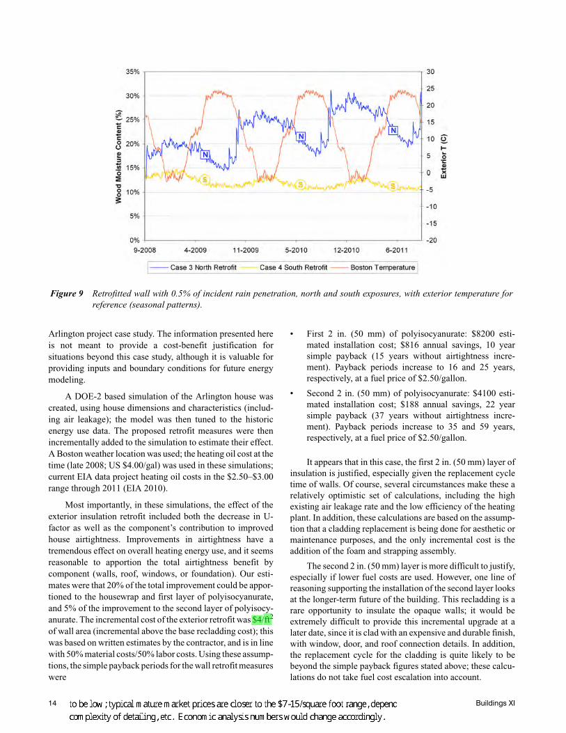
However, when these same rain penetration levels areapplied to the retrofitted wall (Figure 9), the north side showsa seasonally increasing moisture content, exceeding 30% bythe third winter. This indicates a greater sensitivity to rainpenetration. If the rain penetration is reduced by half (to0.25%), the moisture content of the north-side sheathing staysat safe levels, with lower peak moisture contents relative to theoriginal wall (peaks at roughly 17%).
A final set of simulations was run to determine the effectof exterior insulation material properties on rain leakagevulnerability. In addition to foil-faced polyisocyanurate, XPSand EPS were also compared, at the same thickness. AlthoughXPS allows greater drying than foil-faced insulation, at thethickness used in this simulation (4 in., or 102 mm), the perme-ability is sufficiently low (0.25 perm, or 14 ng/Pa·s·m2) that the
wall shows a similar increased vulnerability to moisture accu-mulations. However, the EPS wall appears to have stable mois-ture cycling behavior, and is even drier than the original wallduring the wintertime peaks. Although these simulationsmight point to EPS as a promising option for exterior insula-tion retrofits, there are some drawbacks to this material,including lower R-value per inch, lower compressive strength,poorer workability (edge cutting), and difficulty in detailingthe material as a water control layer/drainage plane.
These results demonstrate that if an exterior foam retrofitis done, it is vital to ensure that windows and other penetra-tions are flashed properly. In fact, this potential damage is astrong reason to consider window replacement, in order toprovide subsill window pan flashings at all window openings.This information was used to persuade the homeowner of theArlington project to take this course of action. Alternately, panflashing might be retrofitted to existing window installations,although it would likely requite removal and reinstallation ofthe windows.
Economic Analysis
Deep energy retrofits often face the criticism of not beingeconomically justified, due to diminishing returns (of space-conditioning energy savings) associated with additional layersof insulation. The retrofit technique presented here is notintended (nor likely) to be a widely deployed measure;however, there is a self-selected market of customers who areinterested in retrofits of this nature, who might not useeconomic payback as their sole value metric.
This analysis is not intended as a complete rigorouseconomic analysis by any means; it is a component of the
Figure 8 Existing wall with 0.5% of incident rain penetration, north and south exposures, with exterior temperature forreference (seasonal patterns).
Buildings XI 13
Arlington project case study. The information presented hereis not meant to provide a cost-benefit justification forsituations beyond this case study, although it is valuable forproviding inputs and boundary conditions for future energymodeling.
A DOE-2 based simulation of the Arlington house wascreated, using house dimensions and characteristics (includ-ing air leakage); the model was then tuned to the historicenergy use data. The proposed retrofit measures were thenincrementally added to the simulation to estimate their effect.A Boston weather location was used; the heating oil cost at thetime (late 2008; US $4.00/gal) was used in these simulations;current EIA data project heating oil costs in the $2.50–$3.00range through 2011 (EIA 2010).
Most importantly, in these simulations, the effect of theexterior insulation retrofit included both the decrease in U-factor as well as the component’s contribution to improvedhouse airtightness. Improvements in airtightness have atremendous effect on overall heating energy use, and it seemsreasonable to apportion the total airtightness benefit bycomponent (walls, roof, windows, or foundation). Our esti-mates were that 20% of the total improvement could be appor-tioned to the housewrap and first layer of polyisocyanurate,and 5% of the improvement to the second layer of polyisocy-anurate. The incremental cost of the exterior retrofit was $4/ft2
of wall area (incremental above the base recladding cost); thiswas based on written estimates by the contractor, and is in linewith 50% material costs/50% labor costs. Using these assump-tions, the simple payback periods for the wall retrofit measureswere
• First 2 in. (50 mm) of polyisocyanurate: $8200 esti-mated installation cost; $816 annual savings, 10 yearsimple payback (15 years without airtightness incre-ment). Payback periods increase to 16 and 25 years,respectively, at a fuel price of $2.50/gallon.
• Second 2 in. (50 mm) of polyisocyanurate: $4100 esti-mated installation cost; $188 annual savings, 22 yearsimple payback (37 years without airtightness incre-ment). Payback periods increase to 35 and 59 years,respectively, at a fuel price of $2.50/gallon.
It appears that in this case, the first 2 in. (50 mm) layer ofinsulation is justified, especially given the replacement cycletime of walls. Of course, several circumstances make these arelatively optimistic set of calculations, including the highexisting air leakage rate and the low efficiency of the heatingplant. In addition, these calculations are based on the assump-tion that a cladding replacement is being done for aesthetic ormaintenance purposes, and the only incremental cost is theaddition of the foam and strapping assembly.
The second 2 in. (50 mm) layer is more difficult to justify,especially if lower fuel costs are used. However, one line ofreasoning supporting the installation of the second layer looksat the longer-term future of the building. This recladding is arare opportunity to insulate the opaque walls; it would beextremely difficult to provide this incremental upgrade at alater date, since it is clad with an expensive and durable finish,with window, door, and roof connection details. In addition,the replacement cycle for the cladding is quite likely to bebeyond the simple payback figures stated above; these calcu-lations do not take fuel cost escalation into account.
Figure 9 Retrofitted wall with 0.5% of incident rain penetration, north and south exposures, with exterior temperature forreference (seasonal patterns).
14 Buildings XI
The energy performance of all of the retrofit projects iscurrently being recorded, and may be presented at a later date.However, the Arlington project is the sole case study where theoriginal mechanical system was retained, thus allowing thedisaggregation of enclosure vs. mechanical savings. Theenergy savings associated with the Concord Four Square arepresented in Pettit (2009).
Building Codes
In buildings that fall under the International BuildingCode (IBC), as opposed to the International Residential Code(IRC), it should be noted that there is a requirement for fire-blocking of exterior concealed wall cavities (ICC 2009,section 717.2.6, Architectural trim). This fireblocking must beplaced at a maximum interval of 20 ft (6096 mm); and limitopen space to 100 ft2 (9.3 m2). This can be addressed, forinstance, by providing fireblocking every two stories, withopenings for cladding drainage and ventilation above andbelow the fireblocking.
CONCLUSION AND FURTHER WORK
There is a substantial opportunity for energy retrofits ofexisting housing stock; however, these upgrades must beundertaken without compromising the durability or health andlife safety of the houses. An exterior retrofit method usingrigid foam sheathing was used on three Boston-area case studyhouses; the assembly and its components are described indetail. There are several advantages to this method, includingthermal performance and durability.
The air barrier performance of these case study houseswas measured; results varied from good to somewhat disap-pointing, although all were a substantial improvement overoriginal performance. Air barrier issues included some loca-tions common to all construction, including windows, doors,and mechanical penetrations. However, it was noted thatcomplex house geometries appeared to be associated withgreater difficulty in obtaining airtightness. Furthermore, theair barrier retrofit technique used at the Bedford Farmhousewas not highly successful; detailing the retrofitted exteriorrigid foam as the primary air barrier is a difficult proposition.
Although this assembly improves durability in otherrespects, hygrothermal analysis shows that the assemblyreduces the ability of the wall to safely dry incidental bulkwater leakage, perhaps by a factor of two. This is a strongmotivation to provide scrupulous water management detailswhen performing this retrofit, particularly in the installation ofwindow subsill pan flashings. The vapor permeance of theinsulation material has a noticeable effect on the drying ofthese systems, with more permeable materials (such as EPS)providing more forgiveness.
Overall, it appears that this technique can improveairtightness, but there are limitations to its ultimate perfor-mance. Moving to greater airtightness levels may require theuse of different techniques, including simplification of thegeometry followed by a fully adhered air barrier membrane
(i.e., “chainsaw retrofit”). A retrofit project is currentlyplanned in Freeport, ME, evaluating this technique. In addi-tion, the use of exterior spray foam as a retrofit air barrier/ther-mal barrier/water control layer is a likely candidate to produceexcellent airtightness; this method is discussed by Coldham(2009) and Straube and Smegal (2009).
ACKNOWLEDGMENTS
The author would like to thank the US Department ofEnergy’s Building America Program for funding most of theresearch underlying this paper, as well as the MassachusettsDepartment of Energy Resources (DOER), which funded theanalysis and testing of the Arlington project.
REFERENCES
Baker, P. and C. Makepeace. 2001. Adapting PERSIST forthe prevention of water accumulation in residentialwood frame construction. Buildings VIII Conference,Clearwater Beach, Florida.
Benesh, I. 2009. REMOTE: A manual. Fairbanks, AK: ColdClimate Housing Research Center (CCHRC).
CGSB. 1986. CAN/CGSB-149.10-M86: Determination ofthe airtightness of building envelopes by the fan depres-surization method. Gatineau, QC: Canadian GeneralStandards Board.
CMHC. 1999. Wood-frame envelopes in the coastal climateof British Columbia: Best practice guide. Ottawa, ON:Canada Mortgage and Housing Corporation.
Coldham, B. 2009. Six proven ways to build energy-smartwalls. Fine Homebuilding Magazine (December/Janu-ary).
Dow Chemical Company Building Solutions. 2007. STYRO-FOAM™ CAVITYMATE™ extruded polystyrene insula-tion product information. http://products.construction.com/swts_content_files/2414/291026.pdf
DOE/EIA. 2005. Residential energy consumption survey:Preliminary housing characteristics tables, TableHC5.1. US Department of Energy/Energy InformationAdministration.
DOE/EIA. 2009. Annual energy review 2008. DOE/EIA-0384(2008). US Department of Energy/Energy Informa-tion Administration.
DOE/EIA. 2010. Short-term energy outlook, Table 4d. USDepartment of Energy/Energy Information Administra-tion. http://www.eia.doe.gov/emeu/steo/pub/contents.html.
Gitt, B. 2009. Existing homes—The next wave. HomeEnergy Magazine (November/December).
Holladay, M. 2009. “Innie” windows or “outie” windows?Green Building Advisor. http://www.greenbuildingadvisor.com/blogs/dept/musings/innie-windows-or-outie-windows.
Hutcheon, N.B. 1964. Principles applied to an insulatedmasonry wall. NRC-IRC Canadian Building Digest
Buildings XI 15
CBD-50. Ottawa, ON: National Research Council ofCanada, Institute for Research in Construction.
IBP. 2008. WUFI (Wärme und Feuchte instationär—Tran-sient Heat and Moisture), version 4.2. Fraunhofer Insti-tute for Building Physics IBP, Holzkirchen, Germany.
ICC. 2009. International building code. Country Club Hills,IL: International Code Council.
Joyce, D. 2009. Retrofitting exterior insulation. Journal ofLight Construction (November).
Lstiburek, J. 2006. Builders guide to cold climates, Ch. 3:Air barriers. Westford, MA: Building Science Press.
Lstiburek, J. 2007. Building sciences: The perfect wall.ASHRAE Journal 49.
Lstiburek, J. 2008. Building sciences: Building America.ASHRAE Journal 50(December).
Lstiburek, J. 2009. Building sciences: Building in extremecold. ASHRAE Journal 51(February).
Lutz, J.D. 2004. Lest we forget, a short history of housing inthe United States. ACEEE Summer Study on EnergyEfficiency in Buildings, Asilomar, California.
Orr, H.W. and R.S. Dumont. 1987. A major energy conserva-tion retrofit of a bungalow. Internal Report 540. Saska-toon, SK: National Research Council of Canada,Institute for Research in Construction.
Pettit, B. 2008. Remodeling for energy efficiency. FineHomebuilding Magazine (April/May).
Pettit, B. 2009. Deep energy retrofit of a Sears Roebuckhouse: A home for the next 100 years. High PerformingBuildings 2(Spring).
Ritchie, T. 1961. Cavity walls. NRC-IRC Canadian BuildingDigest CBD-21. Ottawa, ON: National Research Coun-cil of Canada, Institute for Research in Construction.
Stovall, T., T. Petrie, J. Kosny, P. Childs, J. Atchley, and K.Sissom. 2007. An exploration of wall retrofit best prac-tices. Buildings X Conference, Clearwater Beach, FL.
Straube, J. and E. Burnett. 2005. Building science for build-ing enclosures. Westford, MA: Building Science Press.
Straube, J. and J. Smegal. 2009. Building America specialresearch project: High-R walls case study analysis.Research Report 0903, Building Science Corporation.
Straube, J., R. Van Straaten, and E. Burnett. 2004. Field stud-ies of ventilation drying. Buildings IX Conference,Clearwater Beach, L. (ASHRAE 1091 Project)
Zimmerman, S. 2009. Taking issue: Energy upgradesthreaten older homes. Fine Homebuilding Magazine(April).
16 Buildings XI
CP-1012: Residential Exterior Wall Superinsulation Retrofit Details and Analysis
About this Paper This paper is from the proceedings of the Thermal Performance of the Exterior Envelopes of Whole Buildings XI International Conference, December 5-9, 2010 in
Clearwater, Florida.
About the Authors
Kohta Ueno is an engineer at Building Science Corporation in Somerville, Massachusetts. More information about Kohta Ueno can be found at
www.buildingscienceconsulting.com.
Direct all correspondence to: Building Science Corporation, 30 Forest Street,
Somerville, MA 02143.
Limits of Liability and Disclaimer of Warranty: Building Science documents are intended for professionals. The author and the publisher of this article have used their best efforts to provide accurate and authoritative information in regard to the subject matter covered. The author and publisher make no warranty of any kind, expressed or implied, with regard to the information contained in this article. The information presented in this article must be used with care by professionals who understand the implications of what they are doing. If professional advice or other expert assistance is required, the services of a competent professional shall be sought. The author and publisher shall not be liable in the event of incidental or consequential damages in connection with, or arising from, the use of the information contained within this Building Science document.


![WESTWOOD PLACE CO-OPERATIVE HOMES INVITATION TO …...[Insert Issue Date] Page 1 of 29 Notice to Bidders DATE: Thursday, February 15, 2018 DESCRIPTION: Interior Retrofit and Exterior](https://img.pdfslide.us/doc/110x75/5f0594ac7e708231d413ab7a/westwood-place-co-operative-homes-invitation-to-insert-issue-date-page-1-of.jpg)