Embed Size (px)
Citation preview
PCP Pump
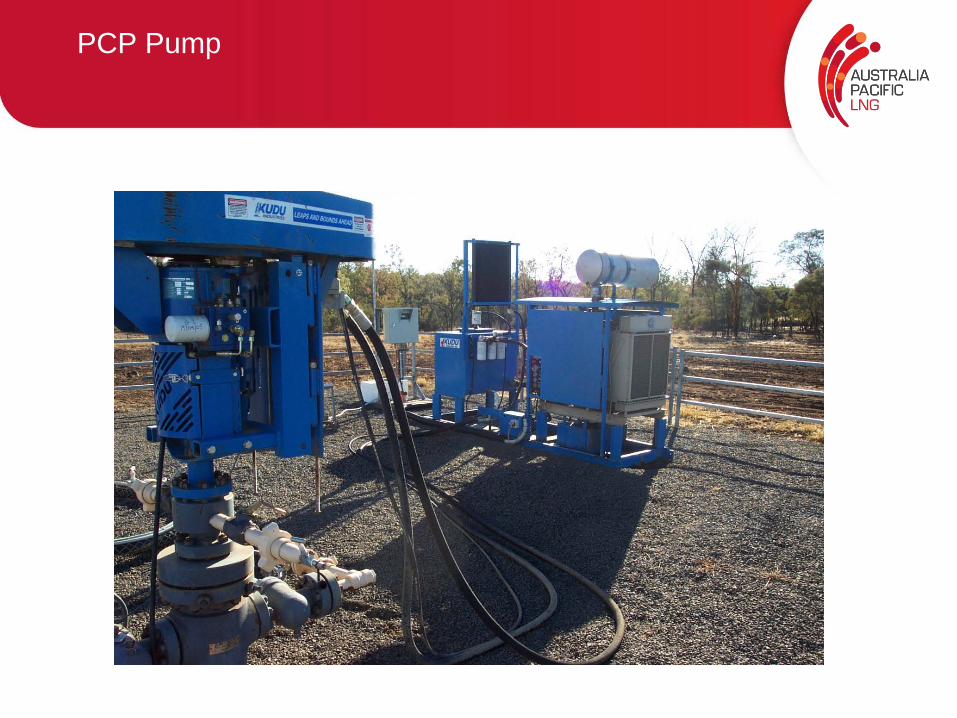
PCP Pump
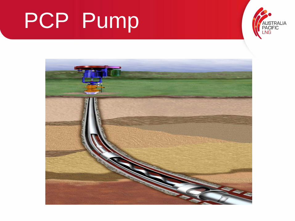
PCP Completion Schematic
• Prime Mover• Drive Head• Stuffing Box• Rod String• PC Pump• Torque Anchor
PCP Design
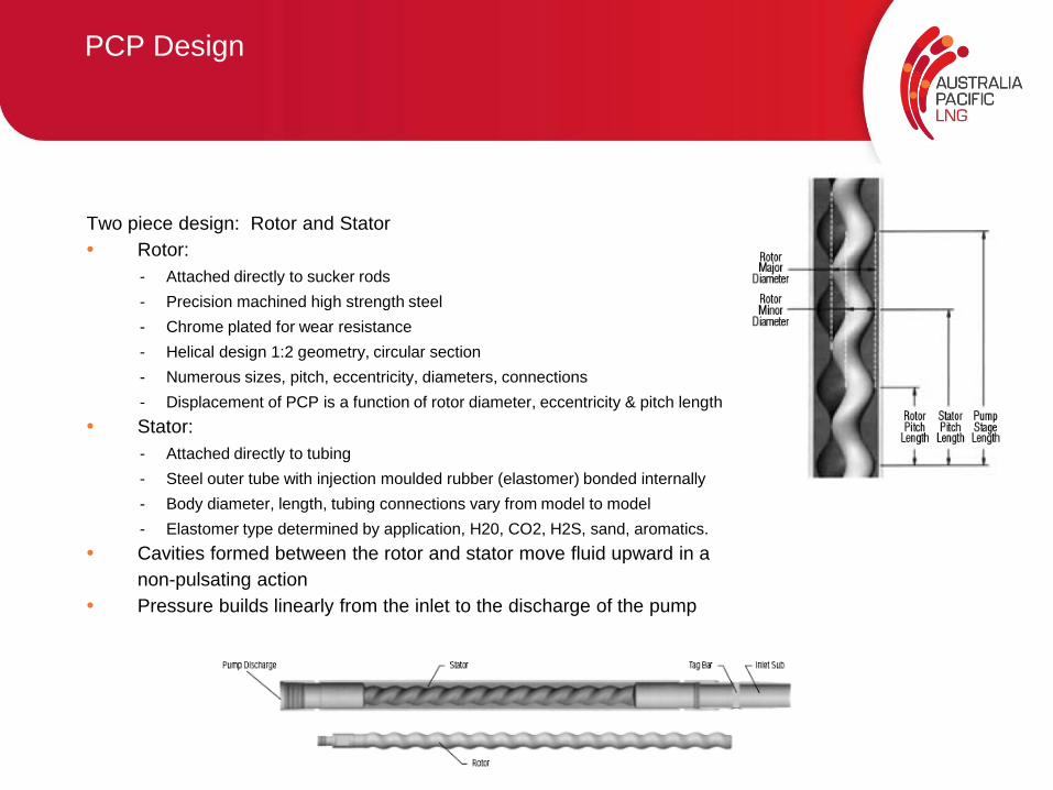
Two piece design: Rotor and Stator• Rotor:
- Attached directly to sucker rods- Precision machined high strength steel - Chrome plated for wear resistance- Helical design 1:2 geometry, circular section- Numerous sizes, pitch, eccentricity, diameters, connections- Displacement of PCP is a function of rotor diameter, eccentricity & pitch length
• Stator:- Attached directly to tubing- Steel outer tube with injection moulded rubber (elastomer) bonded internally- Body diameter, length, tubing connections vary from model to model- Elastomer type determined by application, H20, CO2, H2S, sand, aromatics.
• Cavities formed between the rotor and stator move fluid upward in a non-pulsating action
• Pressure builds linearly from the inlet to the discharge of the pump
PCP Selection
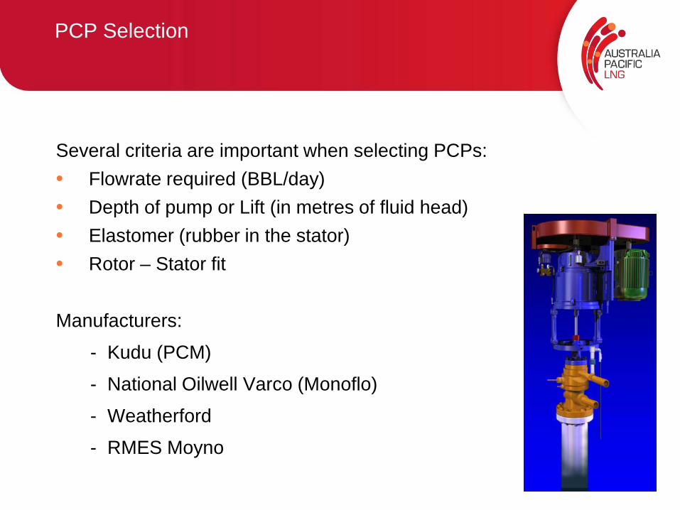
Several criteria are important when selecting PCPs:• Flowrate required (BBL/day)• Depth of pump or Lift (in metres of fluid head)• Elastomer (rubber in the stator)• Rotor – Stator fit
Manufacturers:
- Kudu (PCM)
- National Oilwell Varco (Monoflo)
- Weatherford
- RMES Moyno
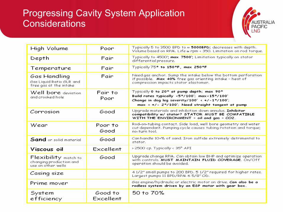
Progressing Cavity System Application Considerations
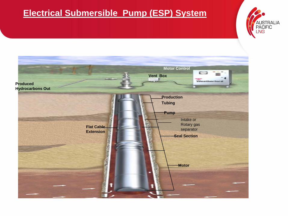
Electrical Submersible Pump (ESP) System
Vent Box
Motor Control
Pump
Motor
ProductionTubing
Produced Hydrocarbons Out
Flat CableExtension
Intake orRotary gasseparator
Seal Section
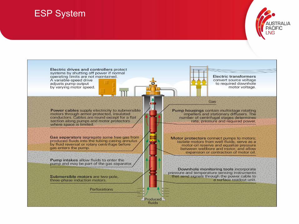
ESP System
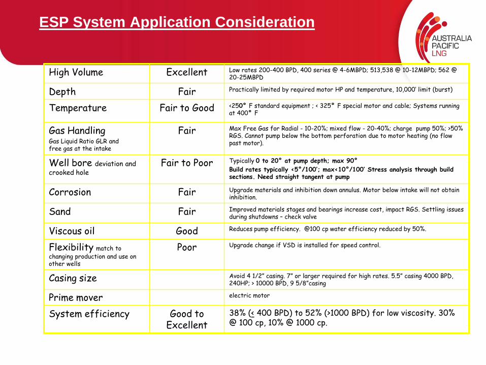
ESP System Application Consideration
High Volume Excellent Low rates 200-400 BPD, 400 series @ 4-6MBPD; 513,538 @ 10-12MBPD; 562 @ 20-25MBPD
Depth Fair Practically limited by required motor HP and temperature, 10,000’ limit (burst)
Temperature Fair to Good <250° F standard equipment ; < 325° F special motor and cable; Systems running at 400° F
Gas Handling Gas Liquid Ratio GLR andfree gas at the intake
Fair Max Free Gas for Radial - 10-20%; mixed flow - 20-40%; charge pump 50%; >50% RGS. Cannot pump below the bottom perforation due to motor heating (no flow past motor).
Well bore deviation and crooked hole
Fair to Poor Typically 0 to 20° at pump depth; max 90°Build rates typically <5°/100’; max<10°/100’ Stress analysis through build sections. Need straight tangent at pump
Corrosion Fair Upgrade materials and inhibition down annulus. Motor below intake will not obtain inhibition.
Sand Fair Improved materials stages and bearings increase cost, impact RGS. Settling issues during shutdowns – check valve
Viscous oil Good Reduces pump efficiency. @100 cp water efficiency reduced by 50%.
Flexibility match to changing production and use on other wells
Poor Upgrade change if VSD is installed for speed control.
Casing size Avoid 4 1/2” casing. 7” or larger required for high rates. 5.5” casing 4000 BPD, 240HP; > 10000 BPD, 9 5/8”casing
Prime mover electric motor
System efficiency Good to Excellent
38% (< 400 BPD) to 52% (>1000 BPD) for low viscosity. 30% @ 100 cp, 10% @ 1000 cp.
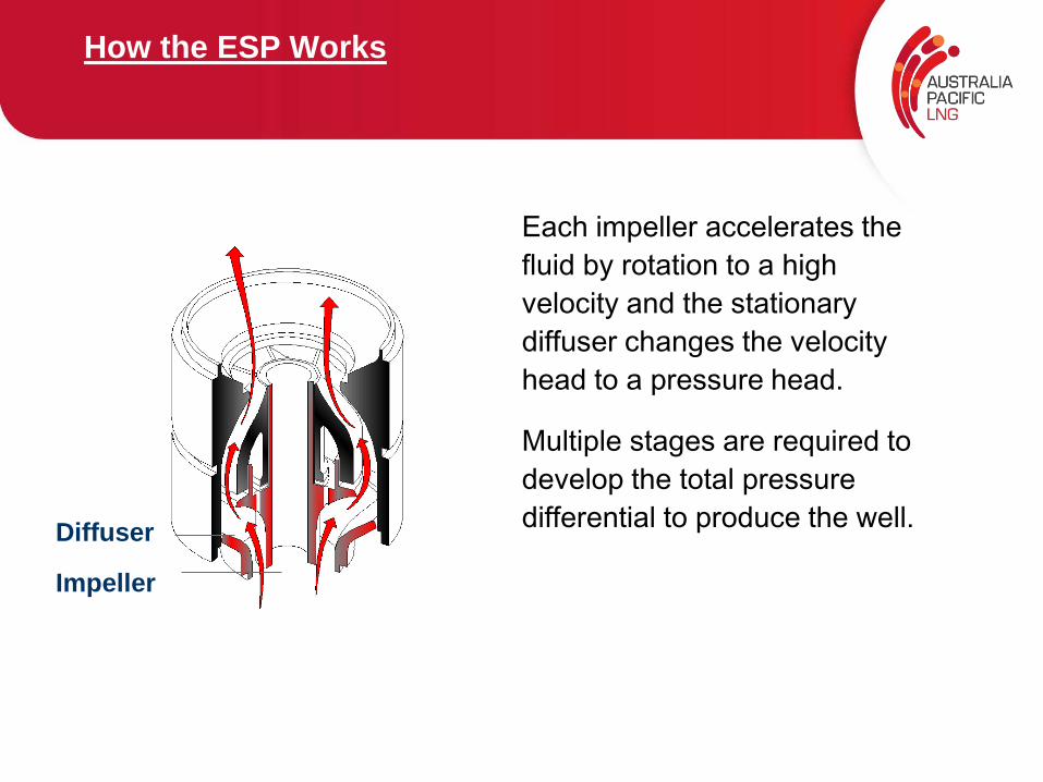
How the ESP Works
Each impeller accelerates the fluid by rotation to a high velocity and the stationary diffuser changes the velocity head to a pressure head.
Multiple stages are required to develop the total pressure differential to produce the well.Diffuser
Impeller
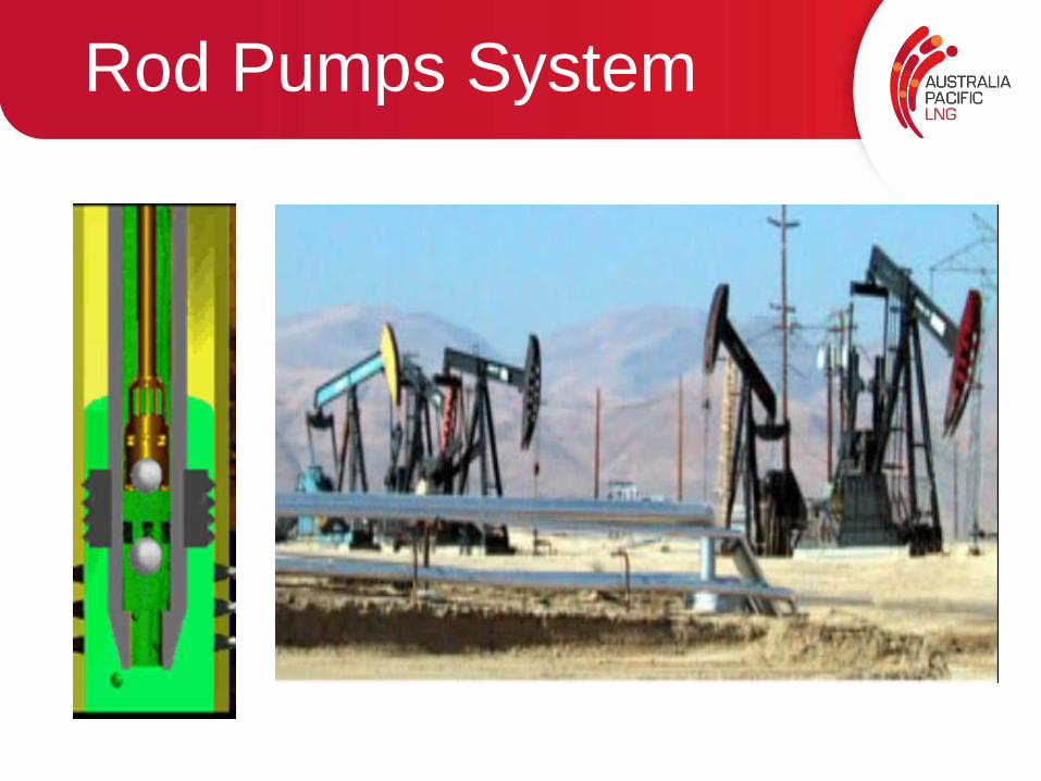
Rod Pumps System
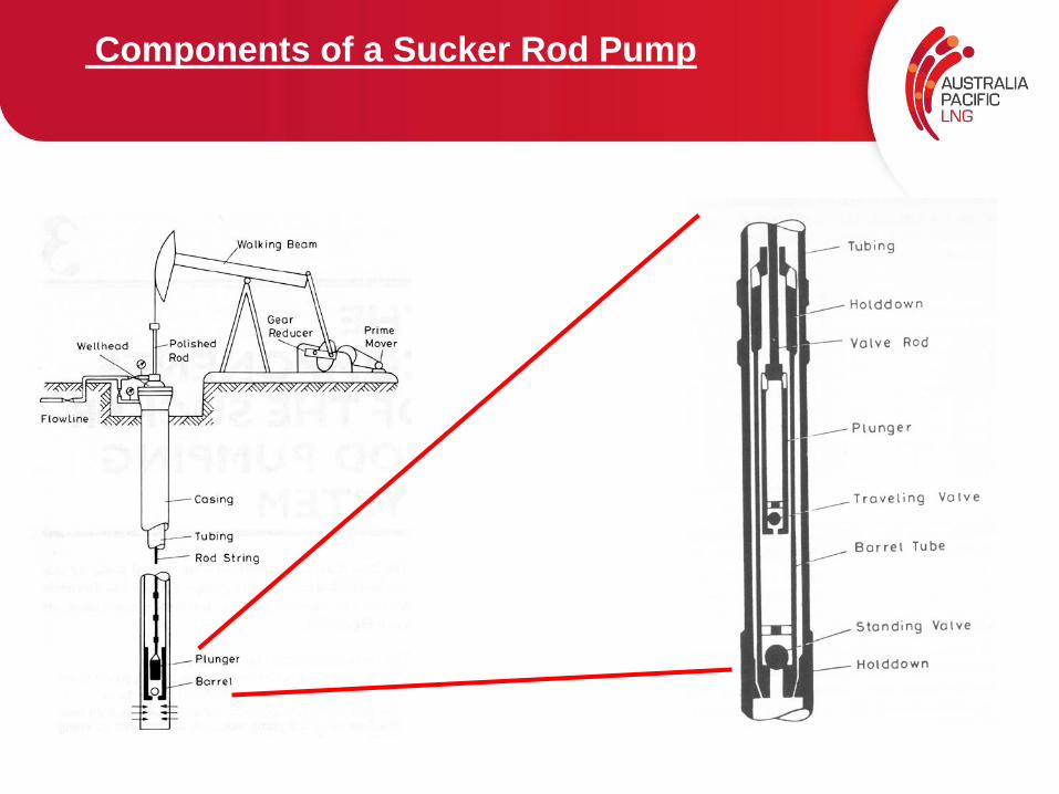
Components of a Sucker Rod Pump
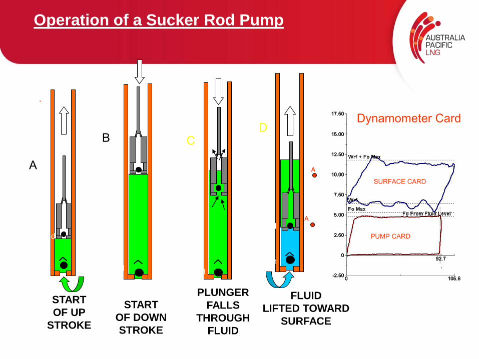
Operation of a Sucker Rod Pump
•
START OF UP
STROKE
SV-open
TV-closed
A A
A
START OF DOWNSTROKE
TV-closed
SV-closed
B B
B
PLUNGER FALLS
THROUGH FLUID
SV-closed
TV-open
CC
C
FLUID LIFTED TOWARD
SURFACE
SV-open
TV-closed
D
D
D
SURFACE CARD
PUMP CARD
START OF UP
STROKE
START OF DOWNSTROKE
Dynamometer Card
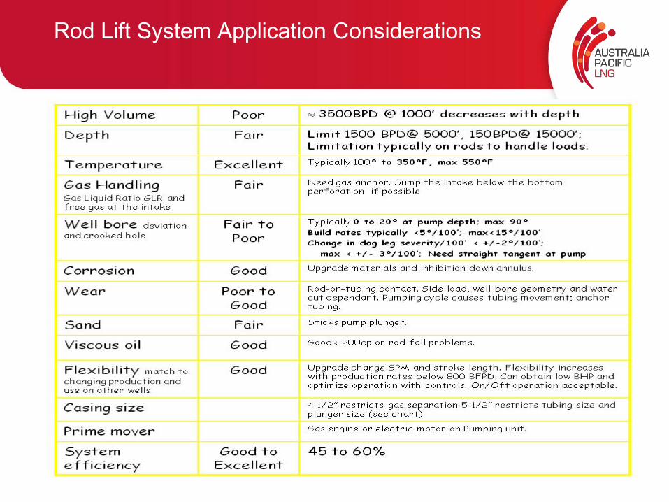
Rod Lift System Application Considerations
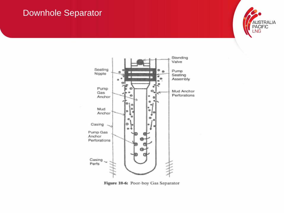
Downhole Separator