Embed Size (px)
Citation preview
HSEHealth & Safety
Executive
Elastomers for fluid containment in offshore oil and gas production: Guidelines and review
Prepared by MERL Ltd for the Health and Safety Executive 2005
RESEARCH REPORT 320
HSEHealth & Safety
Executive
Elastomers for fluid containment in offshore oil and gas production: Guidelines and review
Dr R P Campion, Dr B Thomson and Dr J A Harris MERL Ltd
Tamworth Road Hertford
SG13 7DG
A set of guidelines has been generated and an associated detailed review developed to cover technical aspects associated with the use of elastomers for fluid containment in offshore Oil & Gas production. Information is provided for management systems associated with selecting appropriate material-types and designs and of acceptable operating strategies to reduce risks. The opportunity is also given to learn more about background features of elastomers and their behaviour when exposed to fluids.
Elastomeric components (seals, hoses and many others) are employed extensively for such fluid containment, often in critical locations. Many applications are long-established, with elastomeric components able to function for many years in fluid containment, e.g. up to 20 years or more. However, some deterioration is always taking place. The ever-present point of issue is whether deterioration will lead to failure before the design life is achieved.
In some cases, deterioration can follow predictable routes e.g. with chemical ageing, timedependent properties such as creep or stress relaxation, or fluid-related kinetic factors such as permeation or diffusion. Hence, estimations can be made as to whether or not an elastomeric component so-exposed can function to completion of design life. Other forms of deterioration sometimes seen at high service pressures, such as “explosive” (rapid gas) decompression or seal-housing extrusion damage, are less predictable; here, prior testing of materials under realistic laboratory simulations of operating conditions is necessary to demonstrate the material’s resistance to such failure-modes.
This report and the work it describes were funded by the Health and Safety Executive (HSE). Its contents, including any opinions and/or conclusions expressed, are those of the authors alone and do not necessarily reflect HSE policy.
HSE BOOKS
© Crown copyright 2005
First published 2005
ISBN 0 7176 2969 4
All rights reserved. No part of this publication may bereproduced, stored in a retrieval system, or transmitted inany form or by any means (electronic, mechanical,photocopying, recording or otherwise) without the priorwritten permission of the copyright owner.
Applications for reproduction should be made in writing to: Licensing Division, Her Majesty's Stationery Office, St Clements House, 2-16 Colegate, Norwich NR3 1BQ or by e-mail to [email protected]
ii
ACKNOWLEDGEMENTS
The HSE and the MERL authors wish to thank those listed below and their employers for invaluable comments which have helped focus this document on its objectives for the upstream O & G industry.
Stephen GrovesDavid OrrSteven Paterson, Frans JanssenJohn Boran, Alan GibsonDave ShawPhil EmburyTom FarleyBob JeavonsChris StowellJohn Davis
BP Baker Oil Tools Shell Nexen Petroleum UK Ltd CB&I/John Brown James Walker Parker Seal Gulf Coast Seals Trelleborg Dunlop Oil & Marine
iii
FOREWORD
The HSE require offshore Oil & Gas engineering areas to be managed safely. As part of this, their objectives for this document are:
(i) Generation of a set of guidelines for the use of elastomers in fluid containment offshore. These should provide information for management systems associated with the selection of appropriate designs and acceptable operating strategies.
(ii) Development of a review document relating to the use of elastomers on offshore installations, to be in sufficient detail to lead to the generation of the guidelines, and to act as technical background where required when implementing the guidelines.
This document therefore consists of two parts: Part 1 covering the guidelines and Part 2 the review. The work focuses on elastomer-based components in general upstream oil and gas (O & G) production usage for the UK continental shelf, with limited comments only being made on some other components used here and elsewhere. The components assessed are assumed to contain fluid being transported, either for drilling, completion, production, treatment, control or safety reasons. Other usage of elastomers offshore are not considered herein, such as elastomer-based components (e.g. flexelements) whose sole function is to be part of the supporting structure for all or part of an oilrig etc, or elastomer coating systems, or steel-lined hoses possessing external elastomeric layers.
iv
EXECUTIVE SUMMARY
To ensure the safe use of elastomeric materials offshore, their behavioural characteristics and an awareness of how and where risks might be associated with their usage should be well understood. It should then be possible to identify where suitable risk control measures should be applied for elastomeric components.
Elastomers constitute the most flexible, deformable and elastic of the three classes of the nonmetallic materials “polymers”. As such, elastomers are employed extensively throughout the industry for fluid containment in offshore oil & gas production, often in critical locations. Important applications use elastomeric components as seals (including packers, plugs, repair clamps), hoses/bonded flexible pipes, flexible joints, valve sleeves, pulsation damper bladders and bellows. Many of these applications are long-established; correctly-specified elastomers can function for many years in fluid containment, e.g. up to 20 years or more.
Despite this, the nature of elastomers is such that, when used in contact with fluids and/or subjected to applied forces, significant deterioration may occur. However, modes of deterioration can follow predictable routes such that an elastomeric component so-exposed can continue to function, often to completion of design life. In other instances, change-out might be necessary before design life is complete; prior knowledge of mechanisms involved and procedures to adopt as a consequence is recommended for all such cases.
To develop such knowledge, functional properties, deterioration modes, and factors affecting function performance should be considered. These inform on the sequence of key stages of specification, operation and monitoring. A system audit provides control of all these procedures. Finally, in the event of failure, suitable analysis should be conducted to ascertain causes and provide a basis for any redesign.
This document provides information for safe use of elastomers in fluid containment applications offshore. It is in two parts:
1) As a set of guidelines for management systems associated with the selection of appropriate materials, designs and acceptable operating strategies to reduce risks. Part 1 seeks to guide both on technical matters and on the management of risk during all stages from specification to operation.
2) As a review, to provide further detailed information, sufficient to act as technical background where required when implementing the guidelines – it is a detailed reference.
The two parts are linked by extensive use of footnoted references to assist the reader to obtain extra detail in specific areas.
v

vi
ELASTOMERS FOR FLUID CONTAINMENT IN OFFSHORE OIL &GAS PRODUCTION
Part 1 - GUIDELINES
CONTENTS
1 INTRODUCTION .................................................................................................1
1.1 STRUCTURE OF GUIDELINES ................................................................................2
2 FUNCTIONAL PROPERTIES AND DETERIORATION MODES OFELASTOMERS ....................................................................................................5
2.1 FUNCTIONAL PROPERTIES....................................................................................52.2 FUNCTIONAL PERFORMANCE FACTORS .................................................................52.3 MODES OF DETERIORATION..................................................................................7
3 DESIGN ASPECTS ...........................................................................................11
3.1 MATERIAL SELECTION........................................................................................113.2 SEAL DESIGN ....................................................................................................113.3 DESIGN ASPECTS FOR OTHER COMPONENTS .......................................................12
4 SPECIFICATION ...............................................................................................13
5 QUALIFICATION...............................................................................................17
6 QUALITY CONTROL/QUALITY ASSURANCE DURING MANUFACTURE......19
7 INSTALLATION.................................................................................................21
8 OPERATION AND MONITORING/INSPECTION ..............................................23
9 FAILURE ANALYSIS ........................................................................................25
9.1 ROOT CAUSE ANALYSIS......................................................................................26
10 AUDIT................................................................................................................29
10.1 MANAGERIAL.....................................................................................................2910.2 TECHNICAL .......................................................................................................29
11 BIBLIOGRAPHY FOR GUIDELINES ................................................................33
vii

viii
ELASTOMERS FOR FLUID CONTAINMENT IN OFFSHORE OIL &GAS PRODUCTION
Part 1 – GUIDELINES
Objective: To provide information for the use of elastomers in fluid containment offshore for management systems associated with the selection of appropriate designs and acceptable operating strategies.
1 INTRODUCTION
These guidelines aim to ensure the safe use of elastomeric materials offshore by outlining their behavioural characteristics and indicating where risks might be associated with their usage. It should then be possible to identify where suitable risk control measures should be applied for their components. Relevant technical factors are considered in detail in the review in Part 2, which provides technical background for reference purposes where required. The main focus of Part 1 is on matters affecting the selection of appropriate designs/materials and the management of risk during all stages from specification to operation.
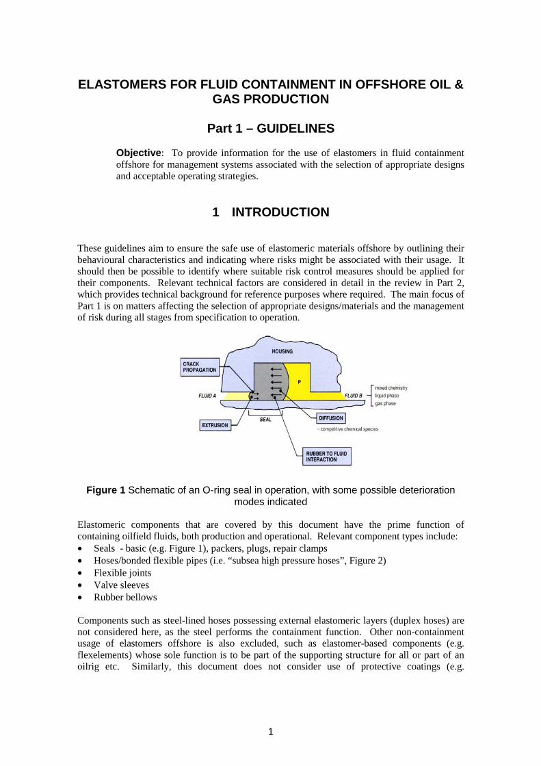
Figure 1 Schematic of an O-ring seal in operation, with some possible deterioration modes indicated
Elastomeric components that are covered by this document have the prime function of containing oilfield fluids, both production and operational. Relevant component types include: • Seals - basic (e.g. Figure 1), packers, plugs, repair clamps • Hoses/bonded flexible pipes (i.e. “subsea high pressure hoses”, Figure 2) • Flexible joints • Valve sleeves • Rubber bellows
Components such as steel-lined hoses possessing external elastomeric layers (duplex hoses) are not considered here, as the steel performs the containment function. Other non-containment usage of elastomers offshore is also excluded, such as elastomer-based components (e.g. flexelements) whose sole function is to be part of the supporting structure for all or part of an oilrig etc. Similarly, this document does not consider use of protective coatings (e.g.
1
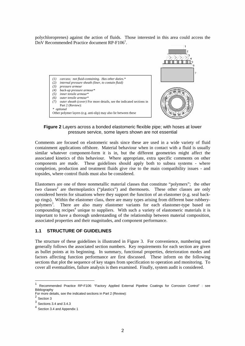
polychloroprenes) against the action of fluids. Those interested in this area could access the DnV Recommended Practice document RP-F1061.
(1) (2) (li luid) (3) (4) (5) (6) (7) ( )
): *
)
carcass; not fluid-containing. Has other duties.* internal pressure sheath ner, to contain fpressure armour back-up pressure armour* inner tensile armour* outer tensile armour* outer sheath cover For more details, see the indicated sections in Part 2 (Review
optional Other polymer layers (e.g. anti-slip may also lie between these
Figure 2 Layers across a bonded elastomeric flexible pipe; with hoses at lower pressure service, some layers shown are not essential
Comments are focused on elastomeric seals since these are used in a wide variety of fluid containment applications offshore. Material behaviour when in contact with a fluid is usually similar whatever component-form it is in, but the different geometries might affect the associated kinetics of this behaviour. Where appropriate, extra specific comments on other components are made. These guidelines should apply both to subsea systems - where completion, production and treatment fluids give rise to the main compatibility issues - and topsides, where control fluids must also be considered.
Elastomers are one of three nonmetallic material classes that constitute “polymers”; the other two classes2 are thermoplastics (“plastics”) and thermosets. These other classes are only considered herein for situations where they support the function of an elastomer (e.g. seal backup rings). Within the elastomer class, there are many types arising from different base rubberypolymers3. There are also many elastomer variants for each elastomer-type based on compounding recipes4 unique to suppliers. With such a variety of elastomeric materials it is important to have a thorough understanding of the relationship between material composition, associated properties and their magnitudes, and component performance.
1.1 STRUCTURE OF GUIDELINES
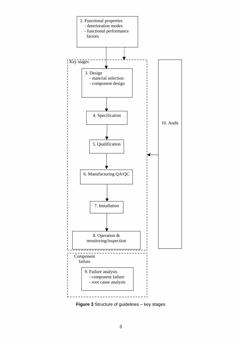
The structure of these guidelines is illustrated in Figure 3. For convenience, numbering used generally follows the associated section numbers. Key requirements for each section are given as bullet points at its beginning. In summary, functional properties, deterioration modes and factors affecting function performance are first discussed. These inform on the following sections that plot the sequence of key stages from specification to operation and monitoring. To cover all eventualities, failure analysis is then examined. Finally, system audit is considered.
1 Recommended Practice RP-F106: “Factory Applied External Pipeline Coatings for Corrosion Control” : see Bibliography For more details, see the indicated sections in Part 2 (Review): 2 Section 3 3 Sections 3.4 and 3.4.3 4 Section 3.4 and Appendix 1
2
/
10. Audit
2. Functional properties - deterioration modes - functional performance factors
4. Specification
3. Design - material selection - component design
5. Qualification
6. Manufacturing QA/QC
7. Installation
8. Operation & monitoring inspection
Key stages
9. Failure analysis - component failure - root cause analysis
Component failure
Figure 3 Structure of guidelines – key stages
3

4
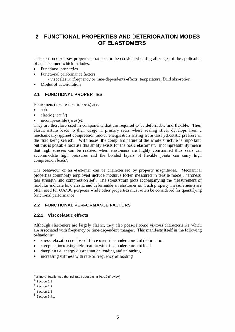
2 FUNCTIONAL PROPERTIES AND DETERIORATION MODES OF ELASTOMERS
This section discusses properties that need to be considered during all stages of the application of an elastomer, which includes: • Functional properties • Functional performance factors
- viscoelastic (frequency or time-dependent) effects, temperature, fluid absorption • Modes of deterioration
2.1 FUNCTIONAL PROPERTIES
Elastomers (also termed rubbers) are: • soft • elastic (nearly) • incompressible (nearly). They are therefore used in components that are required to be deformable and flexible. Their elastic nature leads to their usage in primary seals where sealing stress develops from a mechanically-applied compression and/or energisation arising from the hydrostatic pressure of the fluid being sealed5. With hoses, the compliant nature of the whole structure is important, but this is possible because this ability exists for the basic elastomer6. Incompressibility means that high stresses can be resisted when elastomers are highly constrained thus seals can accommodate high pressures and the bonded layers of flexible joints can carry high compression loads7.
The behaviour of an elastomer can be characterised by property magnitudes. Mechanical properties commonly employed include modulus (often measured in tensile mode), hardness, tear strength, and compression set8. The stress/strain plots accompanying the measurement of modulus indicate how elastic and deformable an elastomer is. Such property measurements are often used for QA/QC purposes while other properties must often be considered for quantifying functional performance.
2.2 FUNCTIONAL PERFORMANCE FACTORS
2.2.1 Viscoelastic effects
Although elastomers are largely elastic, they also possess some viscous characteristics which are associated with frequency or time-dependent changes. This manifests itself in the following behaviours: • stress relaxation i.e. loss of force over time under constant deformation • creep i.e. increasing deformation with time under constant load • damping i.e. energy dissipation on loading and unloading • increasing stiffness with rate or frequency of loading
For more details, see the indicated sections in Part 2 (Review): 5 Section 2.1 6 Section 2.2 7 Section 2.3 8 Section 3.4.1
5
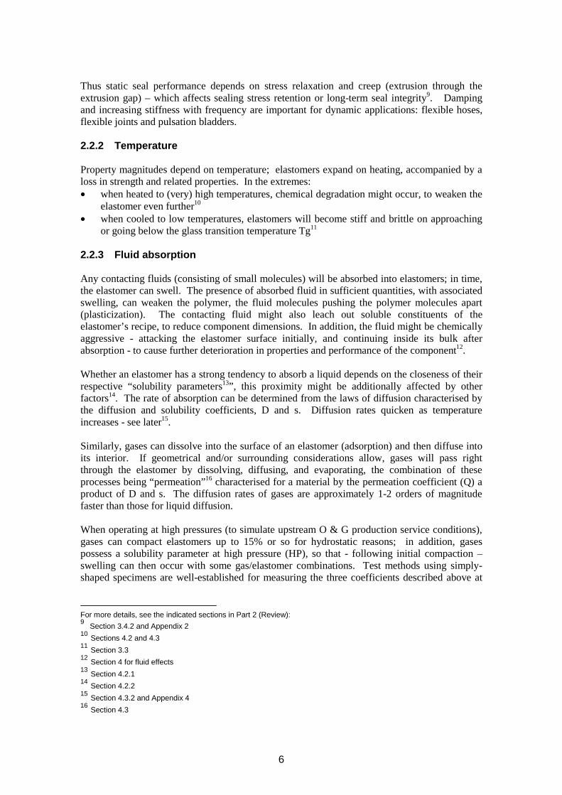
Thus static seal performance depends on stress relaxation and creep (extrusion through the extrusion gap) – which affects sealing stress retention or long-term seal integrity9. Damping and increasing stiffness with frequency are important for dynamic applications: flexible hoses, flexible joints and pulsation bladders.
2.2.2 Temperature
Property magnitudes depend on temperature; elastomers expand on heating, accompanied by a loss in strength and related properties. In the extremes: • when heated to (very) high temperatures, chemical degradation might occur, to weaken the
elastomer even further10
• when cooled to low temperatures, elastomers will become stiff and brittle on approaching or going below the glass transition temperature Tg11
2.2.3 Fluid absorption
Any contacting fluids (consisting of small molecules) will be absorbed into elastomers; in time, the elastomer can swell. The presence of absorbed fluid in sufficient quantities, with associated swelling, can weaken the polymer, the fluid molecules pushing the polymer molecules apart (plasticization). The contacting fluid might also leach out soluble constituents of the elastomer’s recipe, to reduce component dimensions. In addition, the fluid might be chemically aggressive - attacking the elastomer surface initially, and continuing inside its bulk after absorption - to cause further deterioration in properties and performance of the component12.
Whether an elastomer has a strong tendency to absorb a liquid depends on the closeness of their respective “solubility parameters13”, this proximity might be additionally affected by other factors14. The rate of absorption can be determined from the laws of diffusion characterised by the diffusion and solubility coefficients, D and s. Diffusion rates quicken as temperature increases - see later15.
Similarly, gases can dissolve into the surface of an elastomer (adsorption) and then diffuse into its interior. If geometrical and/or surrounding considerations allow, gases will pass right through the elastomer by dissolving, diffusing, and evaporating, the combination of these processes being “permeation”16 characterised for a material by the permeation coefficient (Q) a product of D and s. The diffusion rates of gases are approximately 1-2 orders of magnitude faster than those for liquid diffusion.
When operating at high pressures (to simulate upstream O & G production service conditions), gases can compact elastomers up to 15% or so for hydrostatic reasons; in addition, gases possess a solubility parameter at high pressure (HP), so that - following initial compaction – swelling can then occur with some gas/elastomer combinations. Test methods using simply-shaped specimens are well-established for measuring the three coefficients described above at
For more details, see the indicated sections in Part 2 (Review): 9 Section 3.4.2 and Appendix 2 10 Sections 4.2 and 4.3 11 Section 3.3 12 Section 4 for fluid effects 13 Section 4.2.1 14 Section 4.2.2 15 Section 4.3.2 and Appendix 4 16 Section 4.3
6
high pressures, e.g. 1,000 bar. The coefficients can then be used for other component geometries in predicting fluid permeation rates, break-through times or absorbed concentrations.
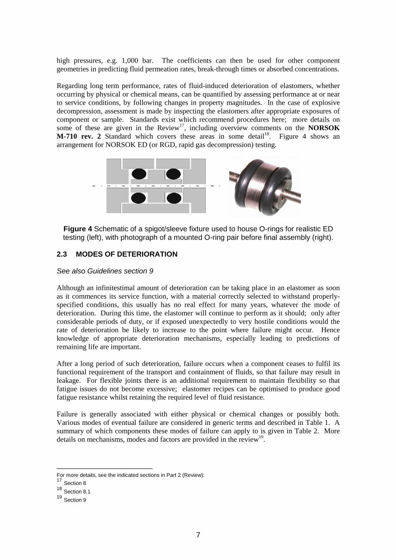
Regarding long term performance, rates of fluid-induced deterioration of elastomers, whether occurring by physical or chemical means, can be quantified by assessing performance at or near to service conditions, by following changes in property magnitudes. In the case of explosive decompression, assessment is made by inspecting the elastomers after appropriate exposures of component or sample. Standards exist which recommend procedures here; more details on some of these are given in the Review17, including overview comments on the NORSOK M-710 rev. 2 Standard which covers these areas in some detail18. Figure 4 shows an arrangement for NORSOK ED (or RGD, rapid gas decompression) testing.
Figure 4 Schematic of a spigot/sleeve fixture used to house O-rings for realistic ED testing (left), with photograph of a mounted O-ring pair before final assembly (right).
2.3 MODES OF DETERIORATION
See also Guidelines section 9
Although an infinitestimal amount of deterioration can be taking place in an elastomer as soon as it commences its service function, with a material correctly selected to withstand properly-specified conditions, this usually has no real effect for many years, whatever the mode of deterioration. During this time, the elastomer will continue to perform as it should; only after considerable periods of duty, or if exposed unexpectedly to very hostile conditions would the rate of deterioration be likely to increase to the point where failure might occur. Hence knowledge of appropriate deterioration mechanisms, especially leading to predictions of remaining life are important.
After a long period of such deterioration, failure occurs when a component ceases to fulfil its functional requirement of the transport and containment of fluids, so that failure may result in leakage. For flexible joints there is an additional requirement to maintain flexibility so that fatigue issues do not become excessive; elastomer recipes can be optimised to produce good fatigue resistance whilst retaining the required level of fluid resistance.
Failure is generally associated with either physical or chemical changes or possibly both. Various modes of eventual failure are considered in generic terms and described in Table 1. A summary of which components these modes of failure can apply to is given in Table 2. More details on mechanisms, modes and factors are provided in the review19.
For more details, see the indicated sections in Part 2 (Review): 17 Section 8 18 Section 8.1 19 Section 9
7
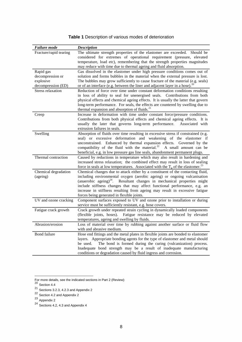
Table 1 Description of various modes of deterioration
Failure mode Description Fracture/rapid tearing The ultimate strength properties of the elastomer are exceeded. Should be
considered for extremes of operational requirement (pressure, elevated temperature, load etc), remembering that the strength properties magnitudes may reduce with time due to thermal ageing and fluid absorption.
Rapid gas Gas dissolved in the elastomer under high pressure conditions comes out of decompression or solution and forms bubbles in the material when the external pressure is lost. explosive The bubbles may grow sufficiently to cause fracture of the material (e.g. seals) decompression (ED) or of an interface (e.g. between the liner and adjacent layer in a hose).20
Stress relaxation Reduction of force over time under constant deformation conditions resulting in loss of ability to seal for unenergised seals. Contributions from both physical effects and chemical ageing effects. It is usually the latter that govern long-term performance. For seals, the effects are countered by swelling due to thermal expansion and absorption of fluids.21
Creep Increase in deformation with time under constant force/pressure conditions. Contributions from both physical effects and chemical ageing effects. It is usually the later that governs long-term performance. Associated with extrusion failures in seals.
Swelling Absorption of fluids over time resulting in excessive stress if constrained (e.g. seal) or excessive deformation and weakening of the elastomer if unconstrained. Enhanced by thermal expansion effects. Governed by the compatibility of the fluid with the material.22 A small amount can be beneficial, e.g. in low pressure gas line seals, abandonment permanent plugs.
Thermal contraction Caused by reductions in temperature which may also result in hardening and increased stress relaxation; the combined effect may result in loss of sealing force in seals at low temperatures. Associated with the Tg of the elastomer.23
Chemical degradation Chemical changes due to attack either by a constituent of the contacting fluid, (ageing) including environmental oxygen (aerobic ageing) or ongoing vulcanisation
(anaerobic ageing)24. Resultant changes in mechanical properties might include stiffness changes that may affect functional performance, e.g. an increase in stiffness resulting from ageing may result in excessive fatigue forces being generated in flexible joints.
UV and ozone cracking Component surfaces exposed to UV and ozone prior to installation or during service must be sufficiently resistant, e.g. hose covers.
Fatigue crack growth Crack growth under repeated strain cycling in dynamically loaded components (flexible joints, hoses). Fatigue resistance may be reduced by elevated temperatures, ageing and swelling by fluids.
Abrasion/erosion Loss of material over time by rubbing against another surface or fluid flow with and abrasive medium.
Bond failure Hose end fittings and the metal plates in flexible joints are bonded to elastomer layers. Appropriate bonding agents for the type of elastomer and metal should be used. The bond is formed during the curing (vulcanization) process. Inadequate bond strength may be a result of inadequate manufacturing conditions or degradation caused by fluid ingress and corrosion.
For more details, see the indicated sections in Part 2 (Review): 20 Section 4.4 21 Sections 3.2.3, 4.2.3 and Appendix 2 22 Section 4.2 and Appendix 2 23 Appendix 2 24 Sections 4.2, 4.3 and Appendix 4
8
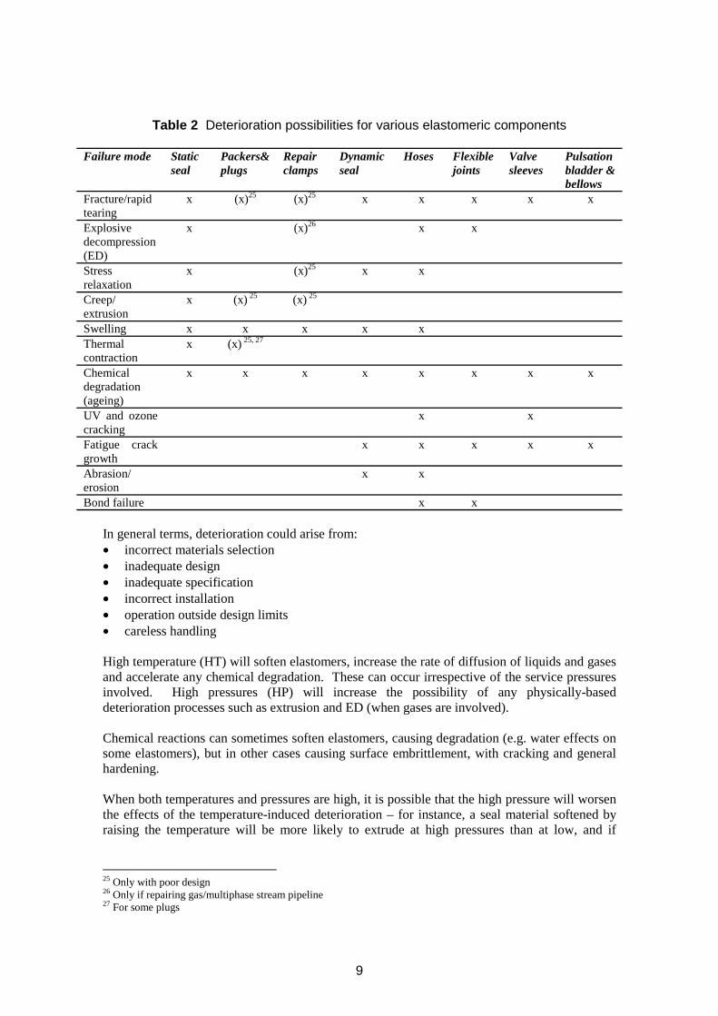
Table 2 Deterioration possibilities for various elastomeric components
Failure mode Static seal
Packers& plugs
Repair clamps
Dynamic seal
Hoses Flexible joints
Valve sleeves
Pulsation bladder & bellows
Fracture/rapid tearing Explosive decompression (ED) Stress relaxation
x
x
x
(x)25 (x)25
(x)26
(x)25
x
x
x
x
x
x
x
x x
Creep/ extrusion
x (x) 25 (x) 25
Swelling Thermal contraction
x x
x (x) 25, 27
x x x
Chemical x x x x x x x x degradation (ageing) UV and ozone x x cracking Fatigue growth
crack x x x x x
Abrasion/ erosion
x x
Bond failure x x
In general terms, deterioration could arise from: • incorrect materials selection • inadequate design • inadequate specification • incorrect installation • operation outside design limits • careless handling
High temperature (HT) will soften elastomers, increase the rate of diffusion of liquids and gases and accelerate any chemical degradation. These can occur irrespective of the service pressures involved. High pressures (HP) will increase the possibility of any physically-based deterioration processes such as extrusion and ED (when gases are involved).
Chemical reactions can sometimes soften elastomers, causing degradation (e.g. water effects on some elastomers), but in other cases causing surface embrittlement, with cracking and general hardening.
When both temperatures and pressures are high, it is possible that the high pressure will worsen the effects of the temperature-induced deterioration – for instance, a seal material softened by raising the temperature will be more likely to extrude at high pressures than at low, and if
25 Only with poor design 26 Only if repairing gas/multiphase stream pipeline 27 For some plugs
9
chemical reactions have caused further softening, the extent of extrusion will be even greater at high pressures. Failures with hoses can again be induced by ED if this phenomenon causes liner deterioration so that the fluid being transported can reach the outer hose layers. These possess less oil-resistance, being designed for other requirements (e.g. the cover material might need to resist sea water, and withstand impacts); hence hose failure is likely to occur relatively soon after liner failure. If it is suspected that such a failure process is under way in production lines subsea, heat seeking devices (where appropriate, carried by underwater divers) should be used for confirmation, seeking hot spots on the outer surface of the cover brought about by the proximity of escaping oil.
Another feature which would allow failure of hoses would be if the end-fittings – chemically bonded to the hose structure during manufacture – should become detached, that is, the curable-adhesive bonding layer should fail. Manufacturers go to extensive lengths in trying to ensure the integrity of these bonded regions during manufacture, with material choice, adhesive choice and quality, and design (the use of tightly-wrapped thick steel wires as reinforcement). In the unlikely event that hose leakage will be suspected during service, this would be a region of the hose requiring inspection. Fatigue aspects might also arise during hose service – it is likely that manufacturers include fatigue qualification tests when making their choice of elastomers prior to manufacture.
10
3 DESIGN ASPECTS
This section considers aspects of design in terms of: • General comments on the factors that should be considered • Responsibilities and procedures for material selection • Considerations for seal design • Design aspects for other elastomeric components
Clearly, each oilfield operation requires its own design criteria. This document does not seek to provide guidance on procedures for designing components. This is seen as the responsibility of manufacturers or suppliers, as initially contracted. However, some factors which might be considered are given in the Review (Part 2)28. All factors (e.g. functional mode of component, environments, planning for contingencies, etc ) should be allowed for. Good experience gained with previous successful designs for equivalent ongoing O & G operations should be incorporated where possible, especially at high pressure/high temperature conditions where there may be a paucity of data regarding material selection, etc. However, previous experiences should not be transferred en bloc unless there is high confidence that all operating factors are identical for previous and new operation. For example, a change in constitution of a gas mixture for a HP operation where all other factors are the same could bring about hitherto un-noted swelling of an elastomer seal (dependent on material type) – see comments in section 2.1 and Review29).
Appropriate design codes, guidelines and/or Standards should be used; some of these are included in the Bibliography list which follows section 8.
3.1 MATERIAL SELECTION
Material selection to meet all specifications may either be the responsibility of the supplier and be based on the specified operating conditions and design life, or be prescribed by the operator based on previous operating experience at these or similar conditions. Selection should be made for specific applications, operating conditions and fluid compatibility; procedure, qualification, etc. The more critical the service, the more rigorous the material selection and qualification process should be. In the Review, section 3.4 covers elastomers as a class, with some subsections covering how various elastomer types will be selected30, with associated comments31.
If the suppliers make the selection of elastomer types for a specific function, they will do so for a particular operation based on specifications provided, making their choice against their knowledge of the selected elastomer’s ability to withstand the conditions. If, instead, the end-user specifies the elastomer type that the supplier shall provide, the end-user is applying his own knowledge in this area; implicitly, in this case, the supplier’s responsibility is reduced to that involving QA/QC so that good quality seals are provided.
3.2 SEAL DESIGN
The design should respond to operational function26, fluid types and conditions; possibilities include HPHT, dynamic, 20 year design life, costs, etc. Usage includes within stators, pumps,
For more details, see the indicated sections in Part 2 (Review): 28 Section 2 29 Section 4.3.2 30 Sections 3.4.3 and 3.4.4 31 Section 3.4.5
11
actuators, plugs, FPSO turrets, packers, well-abandonment packing seals, and as swivels, dynamic seals and gaskets.
3.3 DESIGN ASPECTS FOR OTHER COMPONENTS
Hoses: a specific point is that the inner lining elastomer (the “liner”) and the outer cover material are exposed to two very different environments – production fluid and sea water respectively. Material selection must reflect this26,32, especially regarding fluid compatibility, but also involving material strength and crack-resistance for the cover, which might be subject to impacts during service.
For deluge sleeve valve diaphragms, fatigue considerations must be included.33
For more details, see the indicated sections in Part 2 (Review): 32 Sections 3.4.3, 3.4.4, 3.4.5, and 4 33 Section 7.3
12
4 SPECIFICATION
This sections considers the factors that specification needs to address in order to meet the functional life and design life requirements, so includes the following: • Operating factors that should be considered • Requirements for the specification of materials • The use of application specific data sheets • Storage requirements of elastomeric components
Clearly these relate to the operating conditions, and so this section also includes consideration of the following: • Composition of fluids • Temperatures and pressures • Short-term fluctuations outside the above temperature and pressure conditions • Static and dynamic loads • Regularity of shut downs/decompression cycles • Temperature changes during shut-down
Supplier descriptions may be generic, notated (a) by the rubber-type or (b) by the type that is present in greatest amount. Due to (b), it may therefore be necessary to specify or require a more detailed composition description, particularly for critical applications and/or when no qualification is to be carried out.
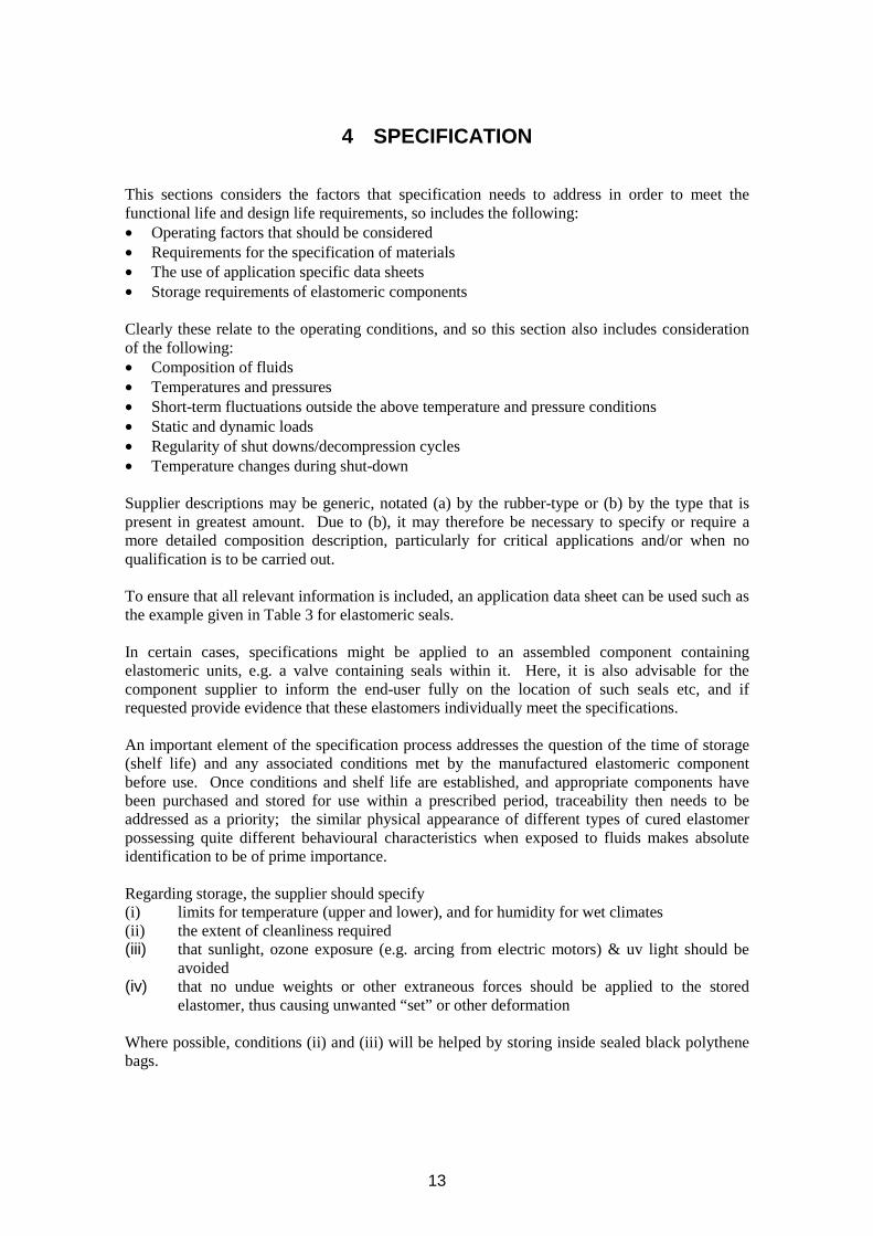
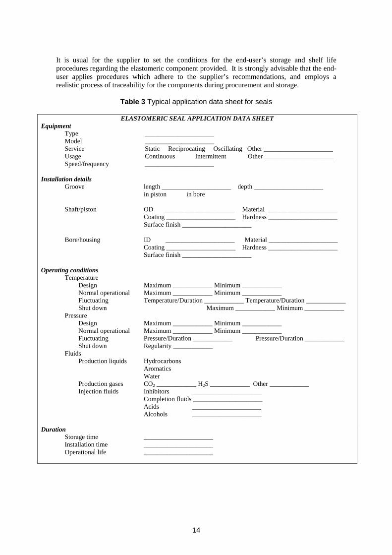
To ensure that all relevant information is included, an application data sheet can be used such as the example given in Table 3 for elastomeric seals.
In certain cases, specifications might be applied to an assembled component containing elastomeric units, e.g. a valve containing seals within it. Here, it is also advisable for the component supplier to inform the end-user fully on the location of such seals etc, and if requested provide evidence that these elastomers individually meet the specifications.
An important element of the specification process addresses the question of the time of storage (shelf life) and any associated conditions met by the manufactured elastomeric component before use. Once conditions and shelf life are established, and appropriate components have been purchased and stored for use within a prescribed period, traceability then needs to be addressed as a priority; the similar physical appearance of different types of cured elastomer possessing quite different behavioural characteristics when exposed to fluids makes absolute identification to be of prime importance.
Regarding storage, the supplier should specify (i) limits for temperature (upper and lower), and for humidity for wet climates (ii) the extent of cleanliness required (iii) that sunlight, ozone exposure (e.g. arcing from electric motors) & uv light should be
avoided (iv) that no undue weights or other extraneous forces should be applied to the stored
elastomer, thus causing unwanted “set” or other deformation
Where possible, conditions (ii) and (iii) will be helped by storing inside sealed black polythene bags.
13
It is usual for the supplier to set the conditions for the end-user’s storage and shelf life procedures regarding the elastomeric component provided. It is strongly advisable that the end-user applies procedures which adhere to the supplier’s recommendations, and employs a realistic process of traceability for the components during procurement and storage.
Table 3 Typical application data sheet for seals
ELASTOMERIC SEAL APPLICATION DATA SHEET Equipment
Type _____________________Model _____________________Service Static Reciprocating Oscillating Other _____________________Usage Continuous Intermittent Other _____________________Speed/frequency _____________________
Installation details Groove length _____________________ depth _____________________
in piston in bore
Shaft/piston OD _____________________ Material _____________________ Coating _____________________ Hardness _____________________ Surface finish _____________________
Bore/housing ID _____________________ Material _____________________ Coating _____________________ Hardness _____________________ Surface finish _____________________
Operating conditions Temperature
Design Maximum ____________ Minimum ____________ Normal operational Maximum ____________ Minimum ____________ Fluctuating Temperature/Duration ____________ Temperature/Duration ____________Shut down Maximum ____________ Minimum ____________
Pressure Design Maximum ____________ Minimum ____________ Normal operational Maximum ____________ Minimum ____________ Fluctuating Pressure/Duration ____________ Pressure/Duration ____________ Shut down Regularity ____________
Fluids Production liquids Hydrocarbons
AromaticsWater
Production gases CO2 ____________ H2S ____________ Other ____________ Injection fluids Inhibitors _____________________
Completion fluids _____________________Acids _____________________Alcohols _____________________
Duration Storage time _____________________Installation time _____________________Operational life _____________________
14
Many organisations have established their own written procedures covering storage/shelf life aspects. More formally, Standards exist34 which should be included when developing specific procedures.
For elastomeric component suppliers, more stringent storage/shelf life procedures apply for their uncured rubber compounds prior to moulding and curing into components.
Subsequent feedback from the end-user to the supplier on the efficiency of their component’s performance during service can help the specification of future operations where conditions are similar, and can reassure the supplier on the quality of his material selection procedures.
For hoses, Standard API 14K covers the parameters against which data should be exchanged when purchasing bonded flexible hose. This document contains a cross-check for the query sheets that the end-users might use.
BS 3574 (now also numbered BSISO 2230) “Storage conditions and shelf life of vulcanised rubber products”. BS 3F68 “Controlled storage of vulcanised rubbers for use in aerospace applications”; conditions apply generally for elastomers.
15
34

16
5 QUALIFICATION
This section considers qualification of materials and/or components in terms of: • When qualification is required • How qualification may be carried out and what standards are applicable • Application of existing knowledge and experience • Use of modelling and simulation
Qualification is required when: • Compatibility of fluids is unknown • Operating conditions are more severe than previous operational experience • New materials are being introduced • Always for critical situations e.g.
- when intervention is difficult e.g. downhole, - under severe conditions e.g. HPHT, H2S
This can be conducted by physical testing, mechanical testing and service-specific exposure or fatigue testing, supported sometimes by simulation using numerical methods such as finite element analysis (FEA). A review and definition stage is required for any new field or operation, particularly if conditions exceed current experience: for example, higher temperatures, pressures, H2S levels. It is important to understand underlying principles behind operations, designs, and assess them in terms of conditions expected.
To make some prediction of long term performance, mechanical, chemical and fracture aspects should be assessed beforehand with accelerated testing. Standards apply in some cases (NORSOK M-710, API 17K, NACE)35: these are discussed in section 8.1 of the Review. NORSOK M-710 is relevant in qualifying sealing materials for chemical ageing and explosive decompression resistance. API 17K is concerned with bonded hose. Various NACE standards apply for the characterisation of elastomer ageing and explosive decompression resistance.
Although general principles of accelerated ageing should be applied wherever possible, specific knowledge should be employed if appropriate. Examples are: • Previous history from a similar well • Behaviour of particular elastomers36 in specific fluids
- FKM in methanol, giving physical weakening; some (not all37) swell excessively thus. However, most applications use methanol/water mixtures for treatments - not 100% methanol - with significantly reduced associated swelling2
- FKM in amine or amide-based corrosion inhibitors31 in either aqueous or hydrocarbon solutions. FKMs again vary greatly in their resistance to highly alkaline (high pH, high amine no.) solutions. Must check with supplier if unsure.
- HNBRs and NBRs in amine or amide-based corrosion inhibitors31 in aqueous solutions; absorption/deterioration increase as above.
Material modelling and simulation of seals and other components is possible by FEA for well-understood situations, e.g. fluid permeation, providing reliable input data are available for the actual gases/material/conditions involved.
For more details, see the indicated sections in Part 2 (Review): 35 Section 8 36 See section 3.4.3 for details of the acronyms for these elastomers 37 Section 4.2.4
17

18
6 QUALITY CONTROL/QUALITY ASSURANCE DURING MANUFACTURE
This section considers quality control and quality assurance during manufacture including: • Procedures and data for mixing and moulding • Appropriate physical testing for materials bonds • Factory acceptance of the finished component
Compound mixing and moulding QC are nowadays assisted by high technology displays in the factory which tell operatives when to perform the various stages of mixing. Hence procedures should be in place, and suitably recorded, which minimise batch-to-batch variability for a specific recipe. With any manufacturing process, identification of individual parts is essential; for rubber compounds, as they are invariably black, whatever the base rubber type and recipe details, accurate labelling, etc of batches and products becomes even more essential.
In seeking methods of detecting flaws in the finished products prior to shipping and service, non-destructive (NDE) techniques are not well developed for elastomers, due to their inherent nature. Therefore, for quality assurance it is necessary to rely on visual inspection and appropriate mechanical test data obtained by component testing of a selection of the final product. For the particular case of adhesion-bonded interfaces - e.g. rubber-rubber bonds and rubber-metal bonds in, for instance, the end-fittings of a hose – these cannot be seen after manufacture to be inspected; the reliability of the bonding system is part of the overall assessment when the hose as a whole is pressure tested. But experience has led to procedures of good-quality surface preparation, adhesive application and assembly techniques that are invariably successful. The essential point is that these procedures are followed; therefore, a high quality ongoing QC procedure is very important.
Factory acceptance tests must be agreed and established. Where appropriate, some high pressure fluid testing should be applied if considered necessary through lack of other data.
19

20
7 INSTALLATION
This section considers the important aspects of installation to be considered for: • Seals in terms of surface finish, lubrication, identification and sensitivity to subsequent
operations • Hoses and larger items in terms of handling and positioning
Correct installation is particularly important for seals. Problems to be avoided include: • The compliance of seals generally allows them to conform to undulations in the housing
surfaces. However, scratches, caused by grit or sharp objects, will provide a potential leakage path, as the seal material may not be able to conform to a sharp-sided “trench”. It is vital therefore that housing surfaces should be protected from such damage, and inspected accordingly before seal fitment. Conditions during fitment must preclude the ingress of grit.
• The high friction between an elastomer and a polished metal surface can lead to twisting of a seal during installation, especially over any rim or the like. This is generally avoided by use of a lubricant. The lubricant must be chosen to be compatible with the seal material, and to avoid contamination. Soapy water is frequently adequate.
• As seal composition, and even exact size, are not evident from visual inspection, it is essential that all seals be clearly marked and/or packaged so that the correct seal for an operation is installed in the housing.
• No high temperature assembly operations, e.g. welding, should take place in the vicinity of the seals before or after installation.
Analogous comments apply to the installation of other components. For large items such as hoses, mechanical means will be used to handle the weights involved. The equipment involved will be powerful; attention is required to avoid using this power to force the component into place without having ensured the correct alignment of component and docking location. For hoses, comments in UKOOA document should be heeded.38
UKOOA Flexible Hose Management Guidelines document, issued by the UK Offshore Operators Association, No. 1 January 2003 (co-sponsored by the Institute of Petroleum, and the Health and Safety Executive).
21
38

22
8 OPERATION AND MONITORING/INSPECTION
This section considers operation and monitoring /inspection in terms of • Limited accessibility of components and techniques that can be used for
monitoring/inspection • Maintaining records of operational conditions for comparison with design specifications
There is a general difficulty of inspecting components in oilfield operations. Seals are usually inaccessible for inspection, so that the monitoring of pressure behaviour in various regions of the system is necessary to check that these components are functioning properly. For hoses above sea level, external inspection can be possible, to check the relatively-unlikely occurrence of whether bulges or cracks have formed (the use of CCTV could be helpful here); for subsea oil-production line situations (with flexible pipes), on occasions divers with heat seeking devices are used, or remote control systems. These infra-red (IR) detectors can assess if hot oil, etc, has penetrated the hose wall construction to approach the outer cover
If the oil-flow is filtered, it can sometimes lead to the detection of a problem at an early stage, as shown in the case study herewith.
For serecordproced
A fullspecifexampfluids such ccarried
Once
UKOJanuary
39
the 16th
j
Case study During a hose operation, a piece of elastomer was filtered out, and identified by a laboratory as being part of a hose liner. The cost of sending divers down to inspect with IR detectors was thus justified; on doing this, failure was detected for
and last hose in the string. On subsequently removing this for fracture analysis, the laboratory discovered complete breakdown throughout the hose liner - a ma or leak in the short term would have been highly likely.
als, leakage itself is usually the next sign sign of failure following indications in pressure ings; a possible means to avoid this is to employ planned changeout and inspection ures, replacing any questionable seals with new ones.
record should be kept of operating conditions – e.g. do they vary from original design ications etc? – and, if appropriate, these should be compared with any failures. As an le, more decompression cycles than specified might have occurred, or the contacting were to be different from those expected. Prior to failure, an educated comparison of any hanges in conditions from those specified should be made to see if a changeout should be out.
again, for hoses, comments in UKOOA document should be heeded.39
OA Flexible Hose Management Guidelines document, issued by the UK Offshore Operators Association, No. 1 2003 (co-sponsored by the Institute of Petroleum, and the Health and Safety Executive).
23

24
9 FAILURE ANALYSIS
This section considers: • The main deterioration mechanisms that may lead to failure in seals • Specific aspects of elastomers that should be considered in a root cause analysis
The main deterioration mechanisms that may lead to failure are: • Seal extrusion • Explosive decompression • Chemical ageing
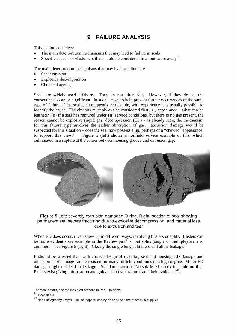
Seals are widely used offshore. They do not often fail. However, if they do so, the consequences can be significant. In such a case, to help prevent further occurrences of the same type of failure, if the seal is subsequently retrievable, with experience it is usually possible to identify the cause. The obvious must always be considered first; (i) appearance – what can be learned? (ii) if a seal has ruptured under HP service conditions, but there is no gas present, the reason cannot be explosive (rapid gas) decompression (ED) - as already seen, the mechanism for this failure type involves the earlier absorption of gas. Extrusion damage would be suspected for this situation – does the seal now possess a lip, perhaps of a “chewed” appearance, to support this view? Figure 5 (left) shows an oilfield service example of this, which culminated in a rupture at the corner between housing groove and extrusion gap.
Figure 5 Left: severely extrusion-damaged O-ring. Right: section of seal showing permanent set, severe fracturing due to explosive decompression, and material loss
due to extrusion and tear
When ED does occur, it can show up in different ways, involving blisters or splits. Blisters can be more evident - see example in the Review part40 - but splits (single or multiple) are also common – see Figure 5 (right). Clearly the single long split there will allow leakage.
It should be stressed that, with correct design of material, seal and housing, ED damage and other forms of damage can be resisted for many oilfield conditions to a high degree. Minor ED damage might not lead to leakage - Standards such as Norsok M-710 seek to guide on this. Papers exist giving information and guidance on seal failures and their avoidance41.
For more details, see the indicated sections in Part 2 (Review): 40 Section 4.4 41 see Bibliography – two Guideline papers, one by an end-user, the other by a supplier.
25
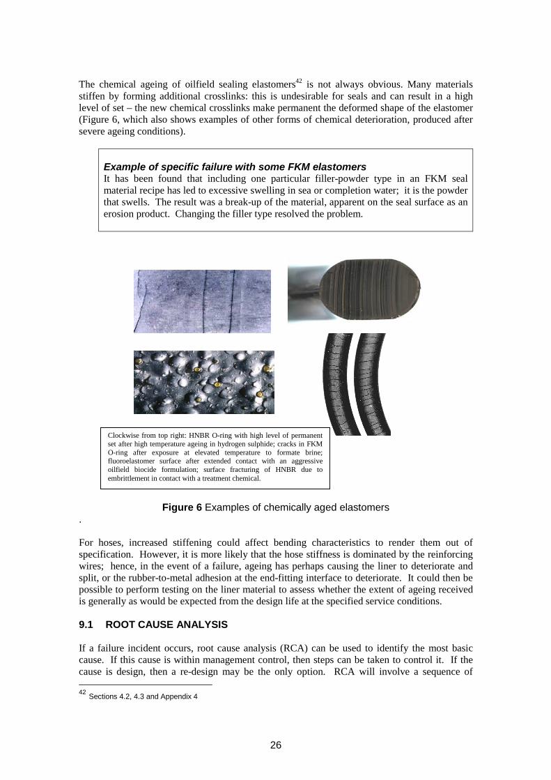
The chemical ageing of oilfield sealing elastomers42 is not always obvious. Many materials stiffen by forming additional crosslinks: this is undesirable for seals and can result in a high level of set – the new chemical crosslinks make permanent the deformed shape of the elastomer (Figure 6, which also shows examples of other forms of chemical deterioration, produced after severe ageing conditions).
Example of specific failure with some FKM elastomers It has been found that including one particular filler-powder type in an FKM seal material recipe has led to excessive swelling in sea or completion water; it is the powder that swells. The result was a break-up of the material, apparent on the seal surface as an erosion product. Changing the filler type resolved the problem.
Clockwise from top right: HNBR O-ring with high level of permanent set after high temperature ageing in hydrogen sulphide; cracks in FKM O-ring after exposure at elevated temperature to formate brine; fluoroelastomer surface after extended contact with an aggressive oilfield biocide formulation; surface fracturing of HNBR due to embrittlement in contact with a treatment chemical.
Figure 6 Examples of chemically aged elastomers .
For hoses, increased stiffening could affect bending characteristics to render them out of specification. However, it is more likely that the hose stiffness is dominated by the reinforcing wires; hence, in the event of a failure, ageing has perhaps causing the liner to deteriorate and split, or the rubber-to-metal adhesion at the end-fitting interface to deteriorate. It could then be possible to perform testing on the liner material to assess whether the extent of ageing received is generally as would be expected from the design life at the specified service conditions.
9.1 ROOT CAUSE ANALYSIS
If a failure incident occurs, root cause analysis (RCA) can be used to identify the most basic cause. If this cause is within management control, then steps can be taken to control it. If the cause is design, then a re-design may be the only option. RCA will involve a sequence of
42 Sections 4.2, 4.3 and Appendix 4
26

collecting data, charting events and causal factors, identifying the critical or direct causes, and the root causes. Barriers to avoid unwanted outcomes may also need to be reviewed. A variety of techniques is available for RCA, detailed description of which is beyond the scope of this document. A discussion of the specific aspects that may need to be considered as part of an RCA of an incident involving elastomeric materials and components used offshore is provided in Part 243.
For more details, see the indicated section in Part 2 (Review): Section 7.4
27
43

28
10 AUDIT
This section proves some questions specific to elastomeric components which can be asked as part of internal auditing procedures and covers • Management systems • Technical aspects
10.1 MANAGERIAL
10.1.1 Policy and strategy
What specific policies and strategic objectives are in place for elastomeric components?
Organisations should have in place policies and strategies that deal with the risks associated with safety, health and environmental concerns – this may be general, but elastomeric components will be included.
10.1.2 Organisation
10.1.2.1 General
What specialist knowledge and expertise is maintained within the organisation?What specific skills and competencies are held within the organisation?Are roles and responsibilities defined?How is communication with all relevant parties ensured?How is the integrity management system organised to address elastomer integrity issues?
10.1.2.2 Planning and implementation
Within a project, how are multiple suppliers managed?What information is used as the basis for specifying elastomeric components?What inspection and monitoring is carried out and which data are recorded?How are these data reviewed and what actions may result?What steps are taken to account for changes in operation conditions that fall outsidespecification?
10.2 TECHNICAL
10.2.1 Factors
10.2.1.1 Design and selection
What basis for design or design codes are used?What procedures are used to select an elastomer solution? (i.e. other solutions considered)?How do the operating conditions influence design/selection procedures or how are operatingconditions taken into account?Under what circumstances is development work carried out and why?What factors of safety are included?If high pressure gas, what steps are taken to avoid ED failure?What considerations are given to the compatibility of the elastomer with fluids in contact?
29
What field experience with similar components can be used to guide design and selection?
10.2.1.2 Seals
If high pressure fluids, what consideration is given to avoidance of extrusion damage?
10.2.1.3 Specification
What precautions are taken to ensure the correct elastomer has been specified ?What information is given to suppliers?What is done to ensure that the specifications will meet operational requirements?How is operational information determined for the specification?For low temperature service, what is done to ensure that the glass transition temperature of theelastomer is always below service temperature?For low temperature service, what is done to ensure that the glass transition temperature of theelastomer is always below shut-down temperatures?For low temperature service, what is done to ensure that either the glass transition temperatureof the elastomer is always below blow-down temperatures, or that allowance is made for thetemporary stiffening of the elastomer during these operations?For high temperature service, what temperature was specified as the service continuous uppertemperature?
10.2.1.4 Qualification
What test methods are considered relevant to the application? What Standards are used?
10.2.1.5 Quality assurance
What quality assurance arrangements are in place?Do they include auditing of supplier’s QA system and monitoring of quality controlsystem/supply product quality.
10.2.1.6 Installation
What precautions are taken to ensure the correct rubber has been supplied and installed?What procedures are in place to ensure correct installation (position, material, personnel-competency)?What precautions are taken to ensure that correct seals are installed – i.e. is there a record of theseal reference used?Was the correct hose installed – was it compatible with the specifications?Was the system installed by competent staff to an approved procedure?
10.2.1.7 Operation and monitoring
How do you account for pressure/temperature losses during operation e.g. on shut-down?What actions are taken if operating conditions are different from the original specification?What inspection regime is in place?What are your conditions for component removal and replacement?What actions are taken in the event of elastomeric component failure?
- Does this include identification of direct and underlying causes? - How are lessons learnt from incidents fed back to prevent recurrence and facilitate continuous improvement?
30

10.2.1.8 Review of system
What arrangements are in place to review the elastomer integrity assurance activities in order to identify weaknesses and areas that need to be improved?
- How are improvements implemented?
31

32
11 BIBLIOGRAPHY FOR GUIDELINES
Design “Seals and Sealing Handbook”, publ. DuPont de Nemours International S.A., Switzerland (1985). UKOOA Flexible Hose Management Guidelines document, issued by the UK Offshore Operators Association, No. 1 January 2003 (co-sponsored by the Institute of Petroleum, and the Health and Safety Executive). UKOOA Flexible Hose Management Guidelines document, issued by the UK Offshore Operators Association, No. 1 January 2003 (co-sponsored by the Institute of Petroleum, and the Health and Safety Executive). “Recommended Practice RP-F106: Factory Applied External Pipeline Coatings for Corrosion Control” - see: <http://exchange.dnv.com/BxWmWeb/TaskManager.asp?WCI=MenuArea&WCE=PMA_6_81 2!816!818&uid=ID20041021710580657197>
Guideline papers S Groves, “Project Guidelines for Selecting Seals for High Pressure Gas Duty and other Oilfield Service”, Proceedings “17th International Conference on Fluid Sealing”, York, UK, publ. BHR Group, Cranfield, Beds, UK, (8 – 10 April 2003). N Page and P Embury, “Elastomeric Seal Failure Analysis and Diagnosis”, Energy Rubber
33

34
ELASTOMERS FOR FLUID CONTAINMENT IN OFFSHORE OIL &GAS PRODUCTION
Part 2 - REVIEW
1 INTRODUCTION .................................................................................................1
2 DESIGN CONSIDERATIONS ..............................................................................3
2.1 SEALS ................................................................................................................32.2 HOSES ...............................................................................................................42.3 OTHERS..............................................................................................................4
3 POLYMERIC MATERIALS ..................................................................................5
3.1 THE GENERAL PLACE OF ELASTOMERS (RUBBERS) WITHIN THE POLYMER CLASS......53.2 POLYMER BASICS ................................................................................................53.3 POLYMER THERMAL TRANSITIONS - TG AND TM.......................................................63.4 ELASTOMERS......................................................................................................73.5 THERMOPLASTICS .............................................................................................143.6 THERMOSETS....................................................................................................15
4 ELASTOMER TYPES TO RESIST FLUID EFFECTS........................................17
4.1 INTRODUCTION TO FLUID COMPATIBILITY .............................................................174.2 LIQUID INTERACTIONS WITH ELASTOMERS ...........................................................184.3 GAS INTERACTIONS WITH ELASTOMERS ...............................................................264.4 EXPLOSIVE DECOMPRESSION .............................................................................304.5 LIFE PREDICTION TECHNIQUE .............................................................................32
5 QA/QC ...............................................................................................................35
6 SEAL FAILURE.................................................................................................37
6.1 SEAL LEAKAGE MODES.......................................................................................376.2 DESIGN, MANUFACTURING AND OPERATIONAL FACTORS IN LEAKAGE ....................37
7 FAILURES FOR OTHER COMPONENTS .........................................................41
7.1 HOSE FAILURE AND LEAKAGE .............................................................................417.2 FLEXIBLE JOINTS...............................................................................................427.3 DELUGE SLEEVE VALVE DIAPHRAGMS .................................................................427.4 ROOT CAUSE ANALYSIS FOR COMPONENT- FAILURE GENERALLY...........................43
8 INDUSTRY STANDARDS .................................................................................47
8.1 NORSOK M-710 REV 2 ....................................................................................478.2 API 17K ...........................................................................................................508.3 NACE ..............................................................................................................518.4 CORPORATE .....................................................................................................51
9 BIBLIOGRAPHY FOR REVIEW ........................................................................53
i

ii
ELASTOMERS FOR FLUID CONTAINMENT IN OFFSHORE OIL &GAS PRODUCTION
Part 2 - REVIEW
Objective: To provide information relating to the use of elastomers on offshore installations in some detail, sufficient to lead to the generation of the guidelines and to act as technical background where required when implementing the guidelines.
1 INTRODUCTION
The foregoing guidelines arise from conclusions made during the review stage of this work, which is now described. The review is made by applying appropriate scientific principles to all factors identified as relevant to the functioning of elastomer (rubber) components employed in offshore oil & gas production. This review was based on existing public domain data and MERL data, knowledge and experience, and includes some assessment of relevant national and international Standards. Greater detail is given in this part of the overall work, which can be consulted if the guideline is considered insufficiently informative for a particular item. For some aspects, even greater detail is provided in four appendices.
Factors assessed
Factors assessed at various locations throughout the review include: • Functional mechanisms of elastomeric components in offshore O & G applications. • Material selection for specific applications, operating conditions and fluid compatibility. • Seal applications and design (could include usage in stators, pumps, actuators, plugs, FPSO
turrets and swivels, dynamic seals and gaskets). • Design aspects for other components. • Quality control during manufacture. • Qualification testing for life assurance. • Material time-dependent properties (stress relaxation, fluid diffusion and permeation),
fatigue where applicable, and material modelling and simulation of seals and another component.
• Seal and hose failure analysis including identification of direct and underlying causes (e.g., chemical ageing, explosive decompression, extrusion, end-fitting disbondment).
1

2
2 DESIGN CONSIDERATIONS
In
pr re.
2.1 SEALS
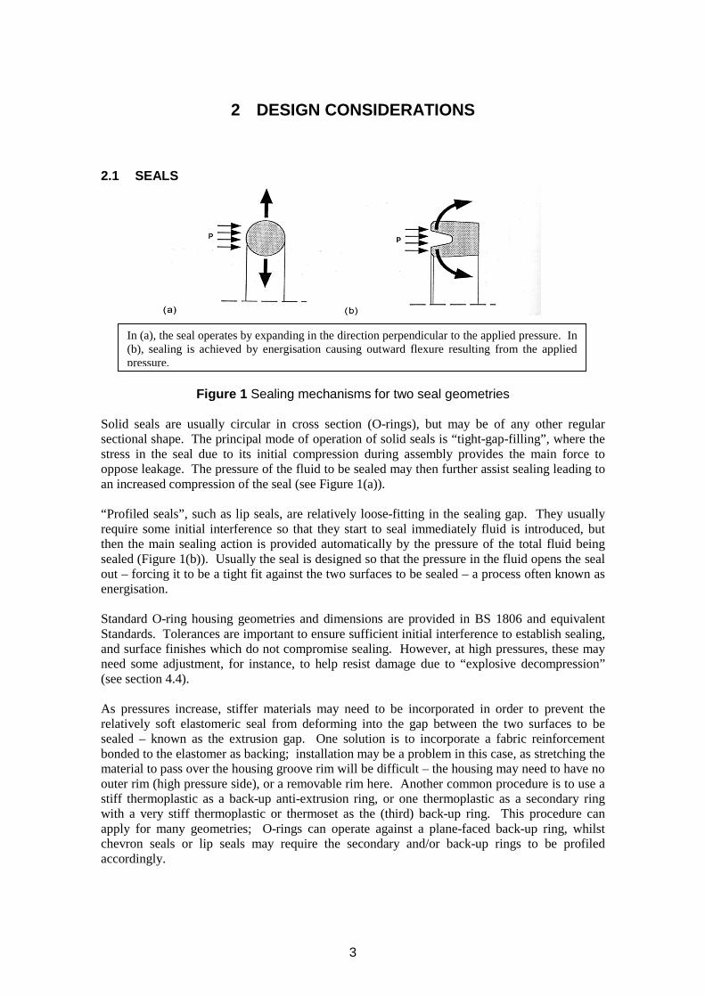
In (a), the seal operates by expanding in the direction perpendicular to the applied pressure. (b), sealing is achieved by energisation causing outward flexure resulting from the applied
essu
Figure 1 Sealing mechanisms for two seal geometries
Solid seals are usually circular in cross section (O-rings), but may be of any other regular sectional shape. The principal mode of operation of solid seals is “tight-gap-filling”, where the stress in the seal due to its initial compression during assembly provides the main force to oppose leakage. The pressure of the fluid to be sealed may then further assist sealing leading to an increased compression of the seal (see Figure 1(a)).
“Profiled seals”, such as lip seals, are relatively loose-fitting in the sealing gap. They usually require some initial interference so that they start to seal immediately fluid is introduced, but then the main sealing action is provided automatically by the pressure of the total fluid being sealed (Figure 1(b)). Usually the seal is designed so that the pressure in the fluid opens the seal out – forcing it to be a tight fit against the two surfaces to be sealed – a process often known as energisation.
Standard O-ring housing geometries and dimensions are provided in BS 1806 and equivalent Standards. Tolerances are important to ensure sufficient initial interference to establish sealing, and surface finishes which do not compromise sealing. However, at high pressures, these may need some adjustment, for instance, to help resist damage due to “explosive decompression” (see section 4.4).
As pressures increase, stiffer materials may need to be incorporated in order to prevent the relatively soft elastomeric seal from deforming into the gap between the two surfaces to be sealed – known as the extrusion gap. One solution is to incorporate a fabric reinforcement bonded to the elastomer as backing; installation may be a problem in this case, as stretching the material to pass over the housing groove rim will be difficult – the housing may need to have no outer rim (high pressure side), or a removable rim here. Another common procedure is to use a stiff thermoplastic as a back-up anti-extrusion ring, or one thermoplastic as a secondary ring with a very stiff thermoplastic or thermoset as the (third) back-up ring. This procedure can apply for many geometries; O-rings can operate against a plane-faced back-up ring, whilst chevron seals or lip seals may require the secondary and/or back-up rings to be profiled accordingly.
3
Normal packers – the seals forming the foundation of wells - are a simple form of seal, where an elastomeric or other flexible material is ‘packed’ into a cavity. The energisation is provided mechanically by compressing the seal. In many cases the energisation can be ‘topped-up’ to prevent leakage after periods of use. Alternatively in PBR systems (polished bore receptacles), which have replaced packers in some of the deepest (HP) wells, seal stacks are used instead of packers. In these, the sequence - primary seal, secondary seal and back-up seal - is repeated several times. This approach is based on the concept that, if the first set of seals fails, the following sets in the sequence will continue the overall sealing (but see later comment under Design etc factors in leakage44 ).
2.2 HOSES
End fitting Hose
Centre line
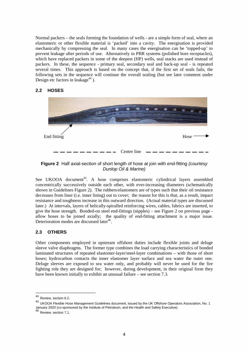
Figure 2 Half axial-section of short length of hose at join with end-fitting (courtesy Dunlop Oil & Marine)
See UKOOA document45. A hose comprises elastomeric cylindrical layers assembled concentrically successively outside each other, with ever-increasing diameters (schematically shown in Guidelines Figure 2). The rubbers/elastomers are of types such that their oil resistance decreases from liner (i.e. inner lining) out to cover; the reason for this is that, as a result, impact resistance and toughness increase in this outward direction. (Actual material types are discussed later.) At intervals, layers of helically-spiralled reinforcing wires, cables, fabrics are inserted, to give the hose strength. Bonded-on steel end-fittings (nipples) – see Figure 2 on previous page allow hoses to be joined axially; the quality of end-fitting attachment is a major issue. Deterioration modes are discussed later46.
2.3 OTHERS
Other components employed in upstream offshore duties include flexible joints and deluge sleeve valve diaphragms. The former type combines the load carrying characteristics of bonded laminated structures of repeated elastomer-layer/steel-layer combinations – with those of short hoses; hydrocarbon contacts the inner elastomer layer surface and sea water the outer one. Deluge sleeves are exposed to sea water only, and probably will never be used for the fire fighting role they are designed for; however, during development, in their original form they have been known initially to exhibit an unusual failure – see section 7.3.
44 Review, section 6.2. 45 UKOOA Flexible Hose Management Guidelines document, issued by the UK Offshore Operators Association, No. 1 January 2003 (co-sponsored by the Institute of Petroleum, and the Health and Safety Executive). 46 Review, section 7.1.
4
3 POLYMERIC MATERIALS
3.1 THE GENERAL PLACE OF ELASTOMERS (RUBBERS) WITHIN THE POLYMER CLASS
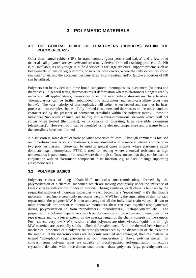
Other than natural rubber (NR), its trans isomers (gutta percha and balata) and a few other materials, all polymers are synthetic and are usually derived from oil-cracking products. As NR is oil-swellable, its only usage in oilfield service is for large structural support systems such as flexelements in tension leg platforms, or in outer hose covers, where the only exposures are to sea water or air, and the excellent mechanical, abrasion-resistant and/or fatigue properties of NR can be utilised.
Polymers can be divided into three broad categories: thermoplastics, elastomers (rubbers) and thermosets. In general terms, thermosets resist deformation whereas elastomers elongate readily under a small applied stress; thermoplastics exhibit intermediate stress-strain characteristics. Thermoplastics can be further subdivided into amorphous and semi-crystalline types (see below). The vast majority of thermoplastics will soften when heated and can thus be heat-processed into complex shapes. Fully-formed elastomers and thermosets on the other hand are characterised by the presence of permanent crosslinks within the polymer matrix; these tie individual “molecular chains” (see below) into a three-dimensional network which will not soften when heated (thermosets), or is capable of tolerating large reversible extensions (elastomers)2. However, both can be moulded using elevated temperature and pressure before the crosslinks have been formed.
A discussion in some detail of basic polymer properties follows. Although comment is focused on properties/characteristics of elastomers, some comment will be made at intervals on the other two polymer classes. These can be used in special cases in areas where elastomers might dominate, e.g. thermoplastic PTFE is used for sealing where chemical resistance at high temperatures is paramount, or in areas where their high stiffness means that they can be used in conjunction with an elastomeric component in its function, e.g. as back-up rings supporting elastomeric seals.
3.2 POLYMER BASICS
Polymers consist of long “chain-like” molecules (macromolecules), formed by the polymerization of a chemical monomer, which are moving continually under the influence of kinetic energy with various modes of motion. During synthesis, each chain is built up by the sequential addition of monomer molecules – each becoming a “repeat unit” – it’s the chain’s molecular mass (more commonly molecular weight, MW) being the summation of that for each repeat unit; the polymer MW is then an average of all the individual chain values. If two or more chemicals are present as alternative monomers, these can react together (copolymerize) during polymerization to form “copolymers”, “terpolymers”, “tetrapolymers” etc. The properties of a polymer depend very much on the composition, structure and interactions of its repeat units and, to a lesser extent, on the average length of the chains comprising the sample. For instance, very low MW (i.e. short chain) polymers are often viscous liquids but all high MW materials are essentially solids – albeit deformable ones. Both the thermal behaviour and mechanical properties of a polymer are strongly influenced by the disposition of chains within the sample. If the macromolecules are randomly oriented and entangled, then the material is termed “amorphous” (e.g., elastomers at room temperature or above; polymer melts). In contrast, some polymer types are capable of closely-packed self-organization to acquire crystalline domains with three-dimensional order; these polymers (e.g., polyethylene) are
5
referred to as “semi-crystalline”, regardless of the actual crystalline content. The remaining non-crystalline regions are amorphous. The whole internal structural arrangement of the polymer is termed its “morphology”.
Internal “free volume” exists within amorphous regions giving rise to chain flexibility, if not restricted by neighbouring crystalline regions. Paradoxically, however, the very root of the flexible nature of polymers, particularly elastomers, reflecting the existence of the free volume through which macromolecules can move when stressed, also provides the “Achilles heel” for attack by external fluid species contacting a polymer (see section 4). If available free volume were not there, the fluid could not enter the polymer matrix, but the polymer would be rigid - as essentially applying to many thermosets. After fluid has entered, the free volume is reduced but not eliminated; subsequently, kinetic movements of chain segments then allow some regeneration of free space (often eventually causing the polymer to swell). Certain polymers are more suitable than others in resisting specific fluids. For situations requiring chemical resistance but little flexibility (e.g., for back-up rings), the presence of crystallinity is highly desirable. In terms of sealing, with flexibility and elasticity required, crystallinity should be avoided where possible: instead, stable crosslinks tying different molecules together lead to the desired properties. Hence, elastomers are used. However, semi-crystalline thermoplastics are sometimes used for seals in cases where their ability to resist chemical attack is the over-riding factor.
3.3 POLYMER THERMAL TRANSITIONS - TG AND TM
log
(Pa)
A
Cross-linked
Tg
Tm
Mod
ulus
Temperature °K
morphous
Crystalline
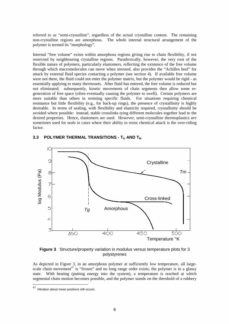
Figure 3 Structure/property variation in modulus versus temperature plots for 3 polystyrenes
As depicted in Figure 3, in an amorphous polymer at sufficiently low temperature, all large-scale chain movement47 is “frozen” and no long range order exists; the polymer is in a glassy state. With heating (putting energy into the system), a temperature is reached at which segmental chain motion becomes possible, and the polymer stands on the threshold of a rubbery
47 Vibration about mean positions still occurs.
6
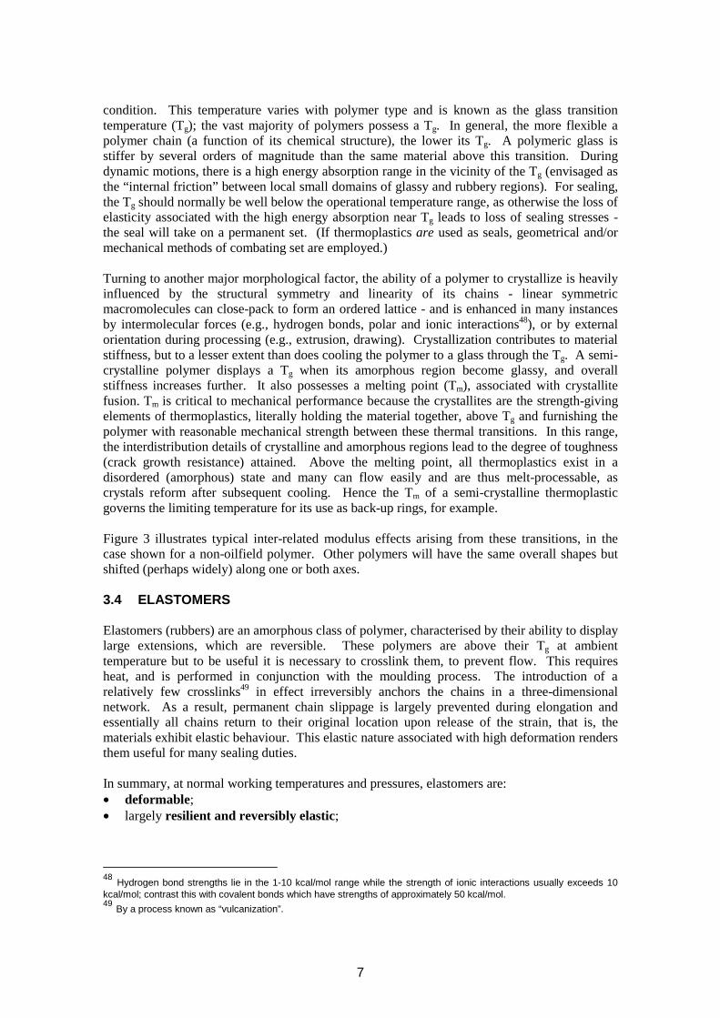
condition. This temperature varies with polymer type and is known as the glass transition temperature (Tg); the vast majority of polymers possess a Tg. In general, the more flexible a polymer chain (a function of its chemical structure), the lower its Tg. A polymeric glass is stiffer by several orders of magnitude than the same material above this transition. During dynamic motions, there is a high energy absorption range in the vicinity of the Tg (envisaged as the “internal friction” between local small domains of glassy and rubbery regions). For sealing, the Tg should normally be well below the operational temperature range, as otherwise the loss of elasticity associated with the high energy absorption near Tg leads to loss of sealing stresses the seal will take on a permanent set. (If thermoplastics are used as seals, geometrical and/or mechanical methods of combating set are employed.)
Turning to another major morphological factor, the ability of a polymer to crystallize is heavily influenced by the structural symmetry and linearity of its chains - linear symmetric macromolecules can close-pack to form an ordered lattice - and is enhanced in many instances by intermolecular forces (e.g., hydrogen bonds, polar and ionic interactions48), or by external orientation during processing (e.g., extrusion, drawing). Crystallization contributes to material stiffness, but to a lesser extent than does cooling the polymer to a glass through the Tg. A semicrystalline polymer displays a Tg when its amorphous region become glassy, and overall stiffness increases further. It also possesses a melting point (Tm), associated with crystallite fusion. Tm is critical to mechanical performance because the crystallites are the strength-giving elements of thermoplastics, literally holding the material together, above Tg and furnishing the polymer with reasonable mechanical strength between these thermal transitions. In this range, the interdistribution details of crystalline and amorphous regions lead to the degree of toughness (crack growth resistance) attained. Above the melting point, all thermoplastics exist in a disordered (amorphous) state and many can flow easily and are thus melt-processable, as crystals reform after subsequent cooling. Hence the Tm of a semi-crystalline thermoplastic governs the limiting temperature for its use as back-up rings, for example.
Figure 3 illustrates typical inter-related modulus effects arising from these transitions, in the case shown for a non-oilfield polymer. Other polymers will have the same overall shapes but shifted (perhaps widely) along one or both axes.
3.4 ELASTOMERS
Elastomers (rubbers) are an amorphous class of polymer, characterised by their ability to display large extensions, which are reversible. These polymers are above their Tg at ambient temperature but to be useful it is necessary to crosslink them, to prevent flow. This requires heat, and is performed in conjunction with the moulding process. The introduction of a relatively few crosslinks49 in effect irreversibly anchors the chains in a three-dimensional network. As a result, permanent chain slippage is largely prevented during elongation and essentially all chains return to their original location upon release of the strain, that is, the materials exhibit elastic behaviour. This elastic nature associated with high deformation renders them useful for many sealing duties.
In summary, at normal working temperatures and pressures, elastomers are: • deformable; • largely resilient and reversibly elastic;
48 Hydrogen bond strengths lie in the 1-10 kcal/mol range while the strength of ionic interactions usually exceeds 10 kcal/mol; contrast this with covalent bonds which have strengths of approximately 50 kcal/mol. 49 By a process known as “vulcanization”.
7
• soft, that is, Young's modulus is low for a solid material, and is a function of strain; the value lies in the range 1-100 MPa with most practical primary sealing materials having moduli nearer the bottom of this range;
• able to maintain constant volume on deformation; with a very high bulk modulus, similar to that of water - they are considered virtually incompressible in the dry state, although some compaction can be noted at high pressures reached in upstream gaseous applications – see section 4.3.2. Furthermore, because of the high ratio of bulk modulus to shear modulus, there is almost no volume change on deformation; the fact that rubber deforms at constant volume, even for high strain deformations, is often wrongly associated with the fact that Poisson's ratio for rubber is very nearly 0.5. Strictly, Poisson's ratio should only be defined at infinitesimal or “classical” strains, and under these conditions the value for rubber is indeed 0.5; if, however, the usual definition of Poisson's ratio (the ratio of lateral contraction to longitudinal extension) is applied at finite strains in rubber, then very much smaller values will result, for instance, “Poisson's ratio” will have a value of about 0.3 at 100% extension;
• able to transmit pressure in a similar way to a fluid, i.e. not only in the direction applied - a very useful feature in many elastomeric seal designs.
For all rubbers, even within one elastomer type, final properties will depend on the recipe (formulation) developed to provide the cured rubber with the correct property mix. The major constituents affecting the performance of a seal elastomer compound, and which can be controlled at the compounding stage of processing, are: • Base rubbery polymer • Cure chemicals • Fillers • Antidegradants • Softeners
Details of elastomer compounding aspects are given in Appendix 1.
3.4.1 Elastomer properties
Table 1 indicates the properties (mechanical and otherwise) commonly quantified and used for design, QA, specification and QC purposes. The Standard numbers for procedures set by a number of Standards organisations for conducting testing for these properties are also included.
8
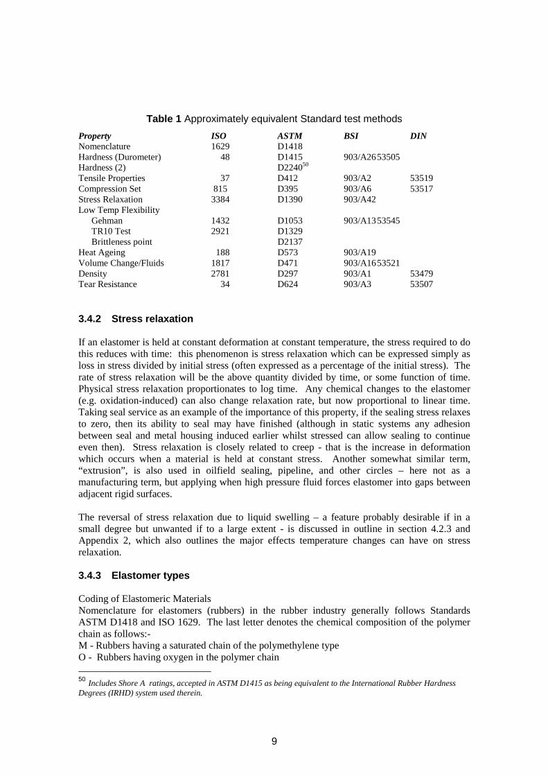
Table 1 Approximately equivalent Standard test methods Property ISO ASTM BSI DIN Nomenclature 1629 D1418 Hardness (Durometer)Hardness (2)
48 D1415 D224050
903/A26 53505
Tensile Properties 37 D412 903/A2 53519 Compression Set 815 D395 903/A6 53517 Stress Relaxation 3384 D1390 903/A42 Low Temp Flexibility
Gehman 1432 D1053 903/A13 53545 TR10 Test 2921 D1329 Brittleness point D2137
Heat Ageing 188 D573 903/A19 Volume Change/Fluids 1817 D471 903/A1653521 Density 2781 D297 903/A1 53479 Tear Resistance 34 D624 903/A3 53507
3.4.2 Stress relaxation
If an elastomer is held at constant deformation at constant temperature, the stress required to do this reduces with time: this phenomenon is stress relaxation which can be expressed simply as loss in stress divided by initial stress (often expressed as a percentage of the initial stress). The rate of stress relaxation will be the above quantity divided by time, or some function of time. Physical stress relaxation proportionates to log time. Any chemical changes to the elastomer (e.g. oxidation-induced) can also change relaxation rate, but now proportional to linear time. Taking seal service as an example of the importance of this property, if the sealing stress relaxes to zero, then its ability to seal may have finished (although in static systems any adhesion between seal and metal housing induced earlier whilst stressed can allow sealing to continue even then). Stress relaxation is closely related to creep - that is the increase in deformation which occurs when a material is held at constant stress. Another somewhat similar term, “extrusion”, is also used in oilfield sealing, pipeline, and other circles – here not as a manufacturing term, but applying when high pressure fluid forces elastomer into gaps between adjacent rigid surfaces.
The reversal of stress relaxation due to liquid swelling – a feature probably desirable if in a small degree but unwanted if to a large extent - is discussed in outline in section 4.2.3 and Appendix 2, which also outlines the major effects temperature changes can have on stress relaxation.
3.4.3 Elastomer types
Coding of Elastomeric Materials Nomenclature for elastomers (rubbers) in the rubber industry generally follows Standards ASTM D1418 and ISO 1629. The last letter denotes the chemical composition of the polymer chain as follows:-M - Rubbers having a saturated chain of the polymethylene type O - Rubbers having oxygen in the polymer chain
50 Includes Shore A ratings, accepted in ASTM D1415 as being equivalent to the International Rubber Hardness Degrees (IRHD) system used therein.
9
R - Rubbers having an unsaturated carbon chain, for example, natural rubber and synthetic rubbers derived at least partly from diolefins Q - Rubbers having silicon and oxygen in the polymer chain T - Rubbers having a sulphur in the polymer chain U - Rubbers having carbon, oxygen and nitrogen in the polymer chain Z - Rubbers having phosphorus and nitrogen in the polymer chain
This nomenclature is adequate for general purpose rubbers but insufficiently descriptive for certain fluoropolymers etc. Hence the intent herein is to use the ASTM D1418 approach as a basis, but provide more details for some rubbers. Use of brackets after the nomenclature can enable extra detail to be given. A full listing of the nomenclature for different elastomer types is given in Table 2; some elastomers are homopolymers, some copolymers, and others ter- or tetrapolymers. In a blend (a well-dispersed mixture of two or more rubbers previously separately polymerised), the major component polymer should appear first followed by a dash (-) and the minor component, or, for 50/50 blends, the polymers listed alphabetically and separated by a stroke (/), as illustrated in Table 2.
10
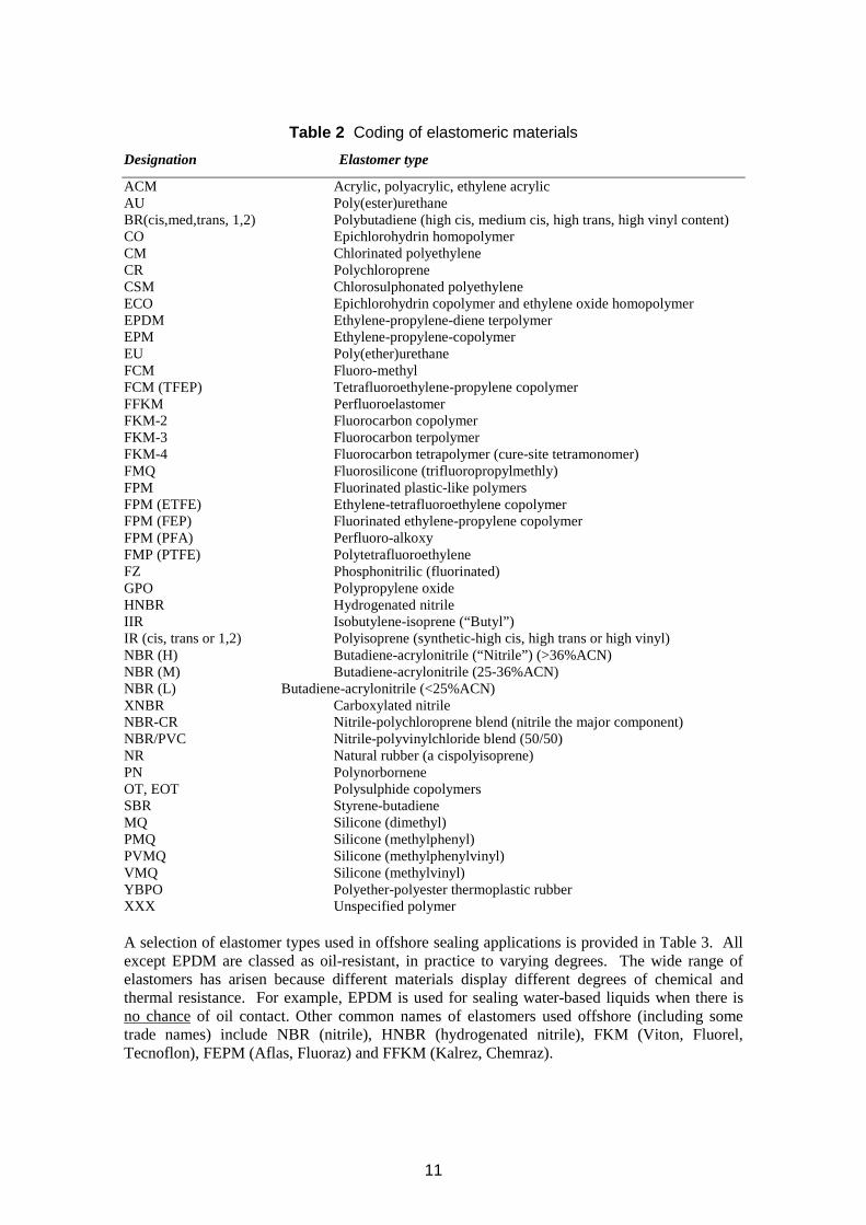
Table 2 Coding of elastomeric materials Designation Elastomer type
ACM Acrylic, polyacrylic, ethylene acrylic AU Poly(ester)urethane BR(cis,med,trans, 1,2) Polybutadiene (high cis, medium cis, high trans, high vinyl content) CO Epichlorohydrin homopolymer CM Chlorinated polyethylene CR Polychloroprene CSM Chlorosulphonated polyethylene ECO Epichlorohydrin copolymer and ethylene oxide homopolymer EPDM Ethylene-propylene-diene terpolymer EPM Ethylene-propylene-copolymer EU Poly(ether)urethane FCM Fluoro-methyl FCM (TFEP) Tetrafluoroethylene-propylene copolymer FFKM Perfluoroelastomer FKM-2 Fluorocarbon copolymer FKM-3 Fluorocarbon terpolymer FKM-4 Fluorocarbon tetrapolymer (cure-site tetramonomer) FMQ Fluorosilicone (trifluoropropylmethly) FPM Fluorinated plastic-like polymers FPM (ETFE) Ethylene-tetrafluoroethylene copolymer FPM (FEP) Fluorinated ethylene-propylene copolymer FPM (PFA) Perfluoro-alkoxy FMP (PTFE) Polytetrafluoroethylene FZ Phosphonitrilic (fluorinated) GPO Polypropylene oxide HNBR Hydrogenated nitrile IIR Isobutylene-isoprene (“Butyl”) IR (cis, trans or 1,2) Polyisoprene (synthetic-high cis, high trans or high vinyl) NBR (H) Butadiene-acrylonitrile (“Nitrile”) (>36%ACN) NBR (M) Butadiene-acrylonitrile (25-36%ACN) NBR (L) Butadiene-acrylonitrile (<25%ACN) XNBR Carboxylated nitrile NBR-CR Nitrile-polychloroprene blend (nitrile the major component) NBR/PVC Nitrile-polyvinylchloride blend (50/50) NR Natural rubber (a cispolyisoprene) PN Polynorbornene OT, EOT Polysulphide copolymers SBR Styrene-butadiene MQ Silicone (dimethyl) PMQ Silicone (methylphenyl) PVMQ Silicone (methylphenylvinyl) VMQ Silicone (methylvinyl) YBPO Polyether-polyester thermoplastic rubber XXX Unspecified polymer
A selection of elastomer types used in offshore sealing applications is provided in Table 3. All except EPDM are classed as oil-resistant, in practice to varying degrees. The wide range of elastomers has arisen because different materials display different degrees of chemical and thermal resistance. For example, EPDM is used for sealing water-based liquids when there is no chance of oil contact. Other common names of elastomers used offshore (including some trade names) include NBR (nitrile), HNBR (hydrogenated nitrile), FKM (Viton, Fluorel, Tecnoflon), FEPM (Aflas, Fluoraz) and FFKM (Kalrez, Chemraz).
11
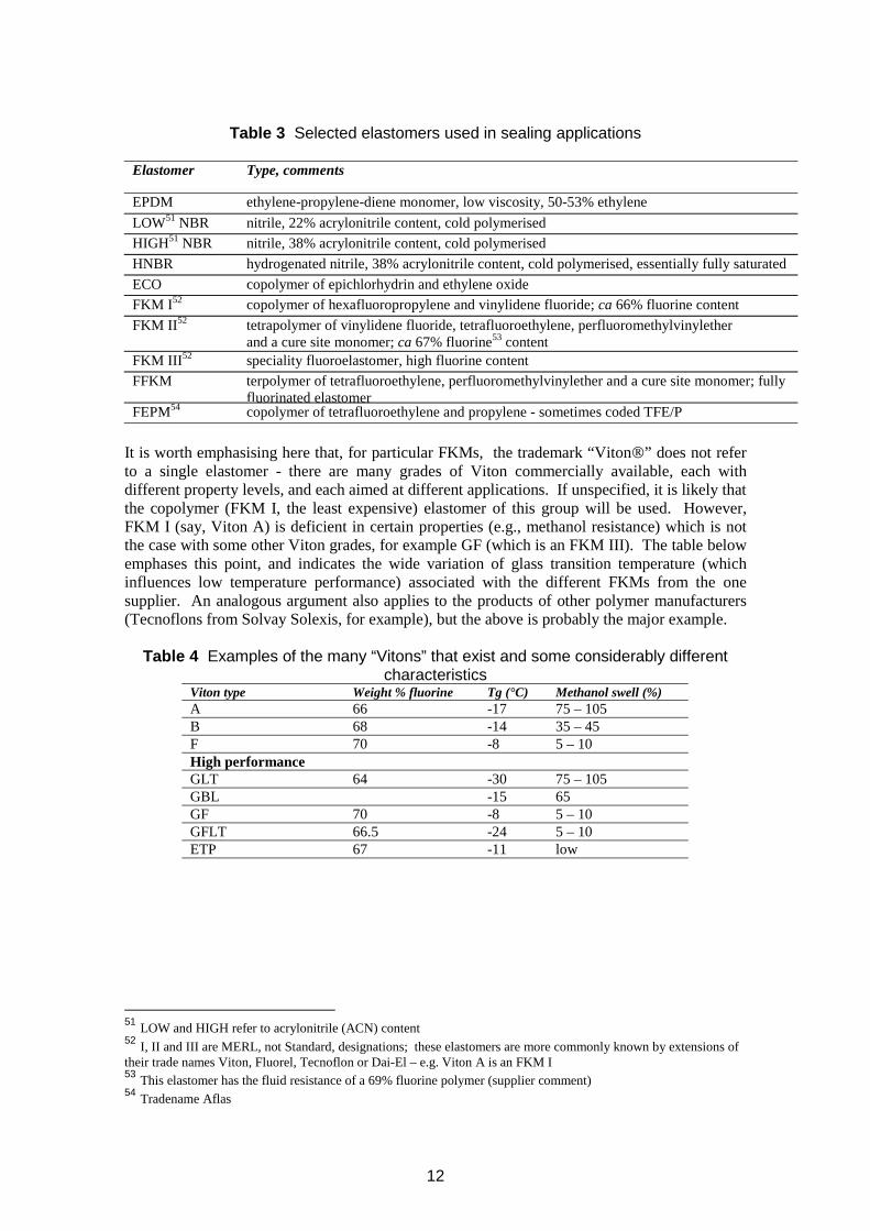
Table 3 Selected elastomers used in sealing applications
Elastomer Type, comments
EPDM ethylene-propylene-diene monomer, low viscosity, 50-53% ethylene LOW51 NBR nitrile, 22% acrylonitrile content, cold polymerised HIGH51 NBR nitrile, 38% acrylonitrile content, cold polymerised HNBR hydrogenated nitrile, 38% acrylonitrile content, cold polymerised, essentially fully saturated ECO copolymer of epichlorhydrin and ethylene oxide FKM I52 copolymer of hexafluoropropylene and vinylidene fluoride; ca 66% fluorine content FKM II52 tetrapolymer of vinylidene fluoride, tetrafluoroethylene, perfluoromethylvinylether
and a cure site monomer; ca 67% fluorine53 content FKM III52 speciality fluoroelastomer, high fluorine content FFKM terpolymer of tetrafluoroethylene, perfluoromethylvinylether and a cure site monomer; fully
fluorinated elastomer FEPM54 copolymer of tetrafluoroethylene and propylene - sometimes coded TFE/P
It is worth emphasising here that, for particular FKMs, the trademark “Viton” does not refer to a single elastomer - there are many grades of Viton commercially available, each with different property levels, and each aimed at different applications. If unspecified, it is likely that the copolymer (FKM I, the least expensive) elastomer of this group will be used. However, FKM I (say, Viton A) is deficient in certain properties (e.g., methanol resistance) which is not the case with some other Viton grades, for example GF (which is an FKM III). The table below emphases this point, and indicates the wide variation of glass transition temperature (which influences low temperature performance) associated with the different FKMs from the one supplier. An analogous argument also applies to the products of other polymer manufacturers (Tecnoflons from Solvay Solexis, for example), but the above is probably the major example.
Table 4 Examples of the many “Vitons” that exist and some considerably different characteristics
Viton type Weight % fluorine Tg (°C) Methanol swell (%) A 66 -17 75 – 105 B 68 -14 35 – 45 F 70 -8 5 – 10 High performance GLT 64 -30 75 – 105 GBL -15 65 GF 70 -8 5 – 10 GFLT 66.5 -24 5 – 10 ETP 67 -11 low
51 LOW and HIGH refer to acrylonitrile (ACN) content 52 I, II and III are MERL, not Standard, designations; these elastomers are more commonly known by extensions of their trade names Viton, Fluorel, Tecnoflon or Dai-El – e.g. Viton A is an FKM I 53 This elastomer has the fluid resistance of a 69% fluorine polymer (supplier comment) 54 Tradename Aflas
12
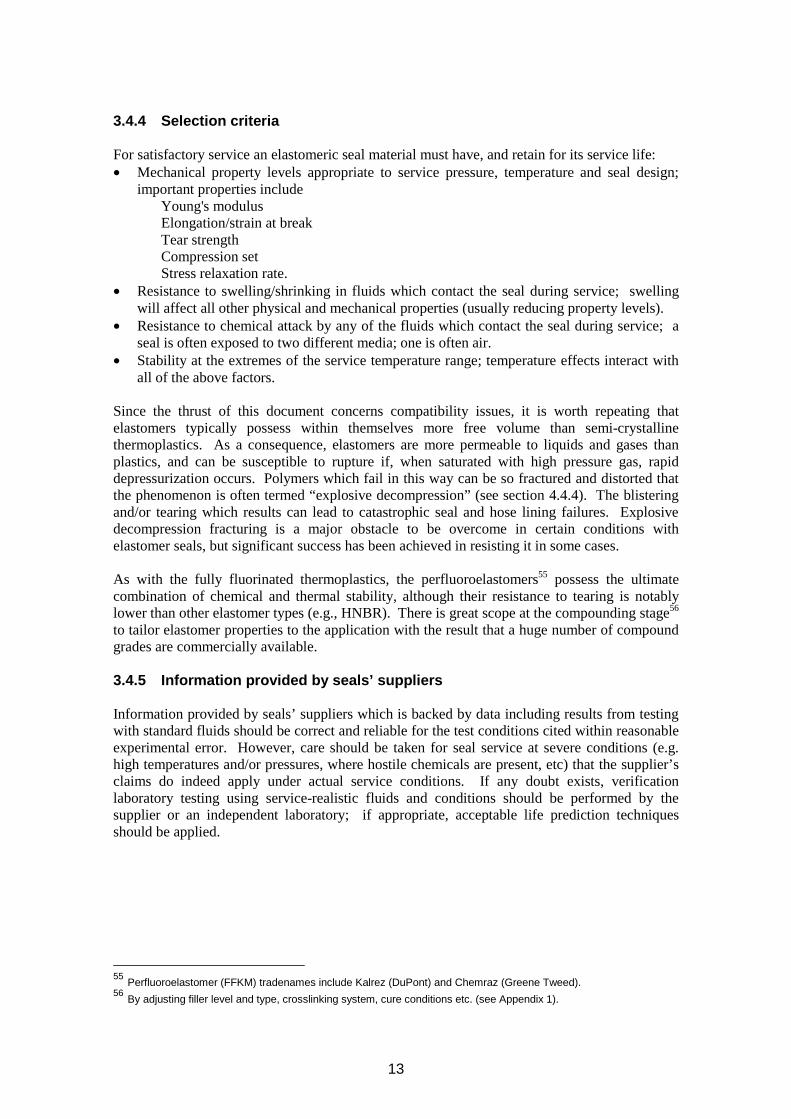
3.4.4 Selection criteria
For satisfactory service an elastomeric seal material must have, and retain for its service life: • Mechanical property levels appropriate to service pressure, temperature and seal design;
important properties includeYoung's modulusElongation/strain at breakTear strengthCompression setStress relaxation rate.
• Resistance to swelling/shrinking in fluids which contact the seal during service; swelling will affect all other physical and mechanical properties (usually reducing property levels).
• Resistance to chemical attack by any of the fluids which contact the seal during service; a seal is often exposed to two different media; one is often air.
• Stability at the extremes of the service temperature range; temperature effects interact with all of the above factors.
Since the thrust of this document concerns compatibility issues, it is worth repeating that elastomers typically possess within themselves more free volume than semi-crystalline thermoplastics. As a consequence, elastomers are more permeable to liquids and gases than plastics, and can be susceptible to rupture if, when saturated with high pressure gas, rapid depressurization occurs. Polymers which fail in this way can be so fractured and distorted that the phenomenon is often termed “explosive decompression” (see section 4.4.4). The blistering and/or tearing which results can lead to catastrophic seal and hose lining failures. Explosive decompression fracturing is a major obstacle to be overcome in certain conditions with elastomer seals, but significant success has been achieved in resisting it in some cases.
As with the fully fluorinated thermoplastics, the perfluoroelastomers55 possess the ultimate combination of chemical and thermal stability, although their resistance to tearing is notably lower than other elastomer types (e.g., HNBR). There is great scope at the compounding stage56
to tailor elastomer properties to the application with the result that a huge number of compound grades are commercially available.
3.4.5 Information provided by seals’ suppliers
Information provided by seals’ suppliers which is backed by data including results from testing with standard fluids should be correct and reliable for the test conditions cited within reasonable experimental error. However, care should be taken for seal service at severe conditions (e.g. high temperatures and/or pressures, where hostile chemicals are present, etc) that the supplier’s claims do indeed apply under actual service conditions. If any doubt exists, verification laboratory testing using service-realistic fluids and conditions should be performed by the supplier or an independent laboratory; if appropriate, acceptable life prediction techniques should be applied.
55 Perfluoroelastomer (FFKM) tradenames include Kalrez (DuPont) and Chemraz (Greene Tweed). 56 By adjusting filler level and type, crosslinking system, cure conditions etc. (see Appendix 1).
13
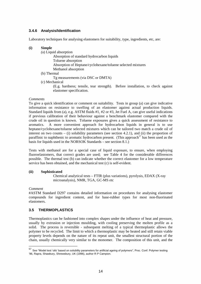
3.4.6 Analysis/Identification
Laboratory techniques for analysing elastomers for suitability, type, ingredients, etc, are:
(i) Simple (a) Liquid absorption
Absorption of standard hydrocarbon liquidsToluene absorptionAbsorption of Heptane/cyclohexane/toluene selected mixturesMethanol absorption
(b) ThermalTg measurements (via DSC or DMTA)
(c) Mechanical (E.g. hardness; tensile, tear strength). Before installation, to check against elastomer specification.
Comments To give a quick identification or comment on suitability. Tests in group (a) can give indicative information on resistance to swelling of an elastomer against actual production liquids. Standard liquids from (a), e.g. ASTM fluids #1, #2 or #3, Jet Fuel A, can give useful indications if previous calibration of their behaviour against a benchmark elastomer compared with the crude oil in question is known. Toluene exposures gives a quick assessment of resistance to aromatics. A more convenient approach for hydrocarbon liquids in general is to use heptane/cyclohexane/toluene selected mixtures which can be tailored two match a crude oil of interest on two counts – (i) solubility parameters (see section 4.2.1), and (ii) the proportion of paraffinic to naphthenic to aromatic hydrocarbon present. (This approach57 has been used as the basis for liquids used in the NORSOK Standards – see section 8.1.)
Tests with methanol are for a special case of liquid exposure, to ensure, when employing fluoroelastomers, that correct grades are used; see Table 4 for the considerable differences possible. The thermal test (b) can indicate whether the correct elastomer for a low temperature service has been obtained, and the mechanical test (c) is self-evident.
(ii) Sophisticated Chemical analytical tests – FTIR (plus variations), pyrolysis, EDAX (X-ray microanalysis), NMR, TGA, GC-MS etc
Comment #ASTM Standard D297 contains detailed information on procedures for analysing elastomer compounds for ingredient content, and for base-rubber types for most non-fluorinated elastomers.
3.5 THERMOPLASTICS
Thermoplastics can be fashioned into complex shapes under the influence of heat and pressure, usually by extrusion or injection moulding, with cooling preserving the molten profile as a solid. The process is reversible - subsequent melting of a typical thermoplastic allows the polymer to be recycled. The limit to which a thermoplastic may be heated and still retain viable property levels depends on the nature of its repeat unit, the smallest structural portion of the chain, usually chemically very similar to the monomer. The composition of this unit, and the
57 See “Model test ‘oils’ based on solubility parameters for artificial ageing of polymers”, Proc. Conf. Polymer testing ’96, Rapra, Shawbury, Shrewsbury, UK (1996), author R P Campion.
14
extent to which it interacts with neighbouring units on the same chain and the units on surrounding chains, largely determines the inherent thermal and mechanical properties of the polymer. For engineering thermoplastics, these materials are sufficiently rigid to allow back-up rings (e.g., PEEK) or even high temperature seals (e.g., PTFE) to be machined out of moulded units.
High performance thermoplastic development and the resulting polymer types are discussed in Appendix 3.
3.6 THERMOSETS
The formation of a thermosetting polymer involves a two stage process. In the first, a low MW prepolymer, which is soluble and fusible, is synthesized. The subsequent conversion of the prepolymer is typically carried out in a heated mould, during which time extensive crosslinking occurs to yield an intractable product58. The resulting material, although hard and sometimes brittle, has excellent dimensional and thermal stability, and creep resistance. Thus typical thermosetting polymers are infusible with generally good chemical resistance and low equilibrium water absorption. The extent of crosslinking determines mechanical properties, and a typical thermoset can be viewed (simplistically) as an extremely rigid elastomer. Chemical bond rotation accompanying extension changes, the general mechanism by which impact energy is dissipated in deformable polymeric materials, cannot occur in these polymers having a rigid three-dimensional molecular architecture; the result is that excess absorbed energy is directed towards the breaking of bonds. Hence thermosets, unlike elastomers of relatively high crosslink density, are prone to brittle fracture. Thermosets contain filler to improve mechanical properties, and the filler type has an influence on chemical resistance. Examples of thermosetting polymers include phenol-formaldehyde, urea-formaldehyde, melamine-formaldehyde, vinyl ester and epoxy resins.
Thermosets are used in advanced composite structures, being combined with glass or carbon fibres in these; oilfield-related pipe duties are now in place. Glass reinforced epoxy is widely used. Developments are currently well advanced for performing in situ pipe repairs on such pipes using fresh thermoset with appropriate application techniques and approved procedures.
Some thermosets cure at ambient temperature, for example, epoxy-based adhesives.
15
58

16
4 ELASTOMER TYPES TO RESIST FLUID EFFECTS
4.1 INTRODUCTION TO FLUID COMPATIBILITY
Elastomers are more prone to fluid uptake than thermoplastics; however, the arguments still apply to the amorphous regions of semi-crystalline thermoplastics, but the effects are usually smaller due to constraints from surrounding crystalline regions.
Progressive degradation is very dependent on the nature of the fluids contacting a seal and on the thermal environment. It may also be influenced by pressure. Additionally, gas pressure is a major factor influencing extent of explosive decompression damage when that applies. The fundamental processes described below are involved in the failure modes listed in section 6, some in more than one. An appreciation of these processes aids the understanding of such failures.
It is important to consider all the details of the local fluid environment of a seal, on the low pressure side as well as on the fluid side - including possible variations around the periphery due to fluid stratification. In particular, atmospheric oxygen can diffuse into a seal and contribute to ageing. It is also important to distinguish physico-chemical effects, such as swelling or leaching, from purely chemical effects, for example, the aforementioned oxidation.
Chemical reactions most commonly occur if two contacting species interact with each other to change to the molecular structure of one or both of them. The influence of increasing temperature is to accelerate chemical reaction rates: hence testing at elevated temperatures is commonly employed in the laboratory as a means of compressing a multi-year material design life to a realistic testing period, to enable life prediction calculations.
Two basic forms of chemical ageing can exist for elastomers – (i) continuation of curing reactions at elevated temperatures due to unstable cure systems, and (ii) exposure to hostile fluids (the latter occurring initially at the elastomer surface, depending on diffusion to access the bulk unless surface cracking provides a more rapid route). In the oilfield industry, hostile fluids can include hydrogen sulphide (produced in some wells), various amines and amides used as corrosion inhibitors, certain brines used in well completion, etc. Hydrogen sulphide will readily attack unsaturated sealing elastomers such as nitriles, so that use of hydrogenated nitrile rubbers (and FKMs) can be beneficial here. Some FKMs are prone to attack by amines at high temperatures, a process accelerated by application of stress (presumably the increase in stored energy also increasing chemical potential). This is an instance of environmental stress cracking (ESC, a common example of this elsewhere in the rubber industry being ozone cracking, which is now controlled well by incorporating suitable antidegradent additives in the elastomer compound). ESC can involve chemical or physico-chemical attacks; some FKMs are attacked by methanol by a process which can be shown to be reversible - and the application of stress again exacerbates it.
Fluids which contact seals are of the following types: • liquid
- may contain one or more chemical species - multi-component liquids; may or may not be miscible
• gas - may contain one or more chemical species
17
• gas/liquid mixtures - each phase may contain one or more chemical species - multi-component liquid phase; may or may not be miscible.
As mentioned above, the affinity a polymer has for a fluid depends on the chemical nature of the polymer repeat unit. Other factors are relevant, in particular, fluid uptake by an elastomer can be limited if there is relatively little free space (free volume) between chains. The efficiency of chain packing, albeit in a disordered array and within the framework of local density fluctuations arising thermally, again depends on detailed molecular structure. Thus, a high glass transition temperature is associated with a low level of free space, a fact which is reflected in the relatively high Tg of many oil resistant polymers.
Fluids absorbed by a polymer can be either chemically hostile or benign. In the latter, mechanical and physical properties may be degraded by the mere physical presence of fluid molecules between polymer chains. Removing the fluid, for example, by evaporation, can largely restore original property levels. However, if the contacting fluid is chemically aggressive, the chemical structure of the elastomer can be essentially59 irreversibly altered by degradation reactions, and its properties permanently deteriorated. Molecular chain backbone unsaturation offers particular sites for chemical attack, for example, by oxygen during thermal aerobic ageing. Elastomers with considerable levels of unsaturation include the nitrile rubbers. The premium oilfield elastomers have little (e.g., HNBR) or no unsaturation (fluoroelastomers), but some are susceptible to chemical degradation in other ways. For instance, the acrylonitrile functional group (which imparts oil resistance) in nitrile rubbers can be attacked by H2S at high temperatures. In many fluoroelastomers containing vinylidene fluoride and hexafluoropropylene monomers, dehydrofluorination occurs in particular environments, which results in the development of unsaturation in the polymer backbone; thus a potential crosslinking site is formed.
4.2 LIQUID INTERACTIONS WITH ELASTOMERS
4.2.1 Solubility parameters
Any liquid or elastomer possesses a “solubility parameter”, δ. This is a thermodynamic property which is related to the energy of attraction between molecules. Thus if two chemical species have the same, or similar, solubility parameter values, when intermixed they are likely to have a strong affinity for one another. Hence an elastomer will possess a drive to absorb a liquid of similar δ, and be swollen by it. As the difference between the solubility parameter values of species increases, so their affinity for each other decreases. Other factors, discussed below, can inhibit the extent of swelling of an elastomer in a compatible liquid. However, for those elastomers which are prone to significant swelling in some liquids, then a good indication of which liquids will swell a particular elastomer can be gained from a knowledge of their respective solubility parameters. The commonest units for δ in the literature are (cal/cm3)1/2; to convert to MPa multiply by 2.05.
59 Unlike physical interactions, chemical reactions are usually deemed irreversible. In fact, this is not always really the case – an equilibrium can exist between the chemical reactants, products and factors such as volume, temperature and pressure. Whether products or reactants dominate depends on the surrounding environment, Le Chatelier’s principle observing that the equilibrium balance will alter to counteract any change in one of the participant-variables in the equilibrium. For instance, if a product is removed (e.g. as often occurs when it is a gas), the “forward” reaction is favoured in a thermodynamically-driven attempt to replace the removed species.
18
Thermodynamically, intermixing as above arises from achieving a negative free energy from the process; in turn, this arises by balancing a contribution from enthalpy (heat content) with another from entropy (involving structural aspects). The solubility parameter reflects the enthalpic term.
Solubility parameter spectroscopy (SPS) is a means of determining the δ value of an elastomer. Replicate elastomer samples are immersed in a series of carefully selected liquids or miscible liquid mixtures, each of known δ, and a plot (spectrum) of swelling vs. liquid solubility parameter thus developed. The δ value coinciding with the maximum of the plot is taken as the δ value for the elastomer. The width of the solubility parameter peak in SPS indicates the δ range across which substantial swelling of an elastomer can occur in low viscosity solvents. As solvent viscosity increases, the width and height of the peak are reduced.
Intermediate liquid δ values are obtained by mixing liquids of known solubility parameter. The δ value of the mixture is equal to the volume-weighted sum of the individual component liquid δ values. This phenomenon can have important consequences in some applications. Thus the mass uptake of a miscible liquid mixture by an elastomer may be very much greater than the swelling which would occur in the presence of either one of the component liquids alone. The mixture could of course comprise more than two liquid components, and an analogous situation would apply.
The technique of reverse solubility parameter spectroscopy (RSPS) was developed60 to determine the δ value for a liquid (e.g., an oil), from a series of swelling measurements using a range of elastomers of known δ. In this way, δ for crude Brent oil has been found to be 8.2
1/2(cal/cm3) .
Solubility parameters are perhaps not listed as frequently as many other properties: Table 5 lists the δ values of a number of common solvents, including some associated with oil production. Also included in the table are the solubility parameter values for the elastomers tabulated in Table3; these were determined using solubility parameter spectroscopy.
Developed by MERL personnel
19
60
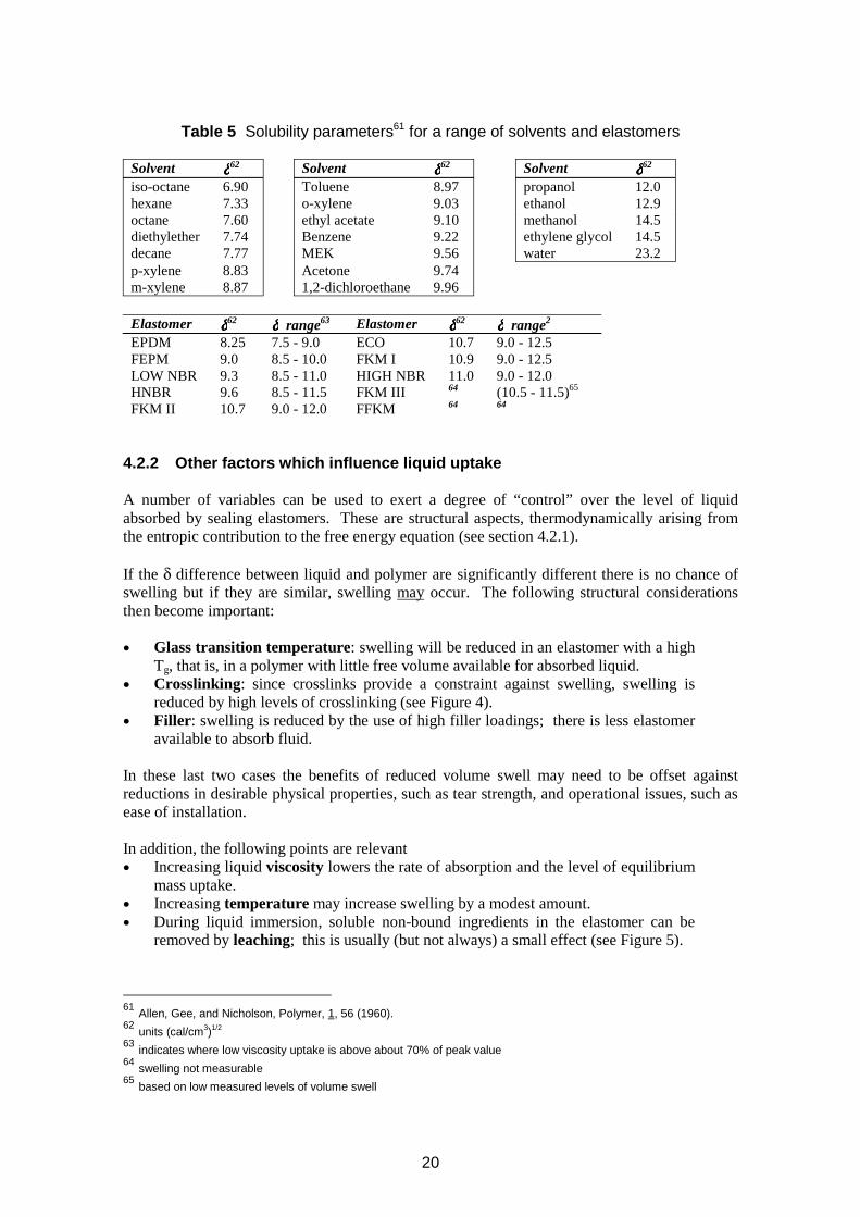
Table 5 Solubility parameters61 for a range of solvents and elastomers
δδδδ62 δδδδ62 δδδδ62Solvent Solvent Solvent iso-octane 6.90 Toluene 8.97 hexane 7.33 o-xylene 9.03 octane 7.60 ethyl acetate 9.10 diethylether 7.74 Benzene 9.22 decane 7.77 MEK 9.56
propanol 12.0 ethanol 12.9 methanol 14.5 ethylene glycol 14.5 water 23.2
p-xylene 8.83 Acetone 9.74 m-xylene 8.87 1,2-dichloroethane 9.96
δδδδ62 δδδδ62Elastomer δδδδ range63 Elastomer δδδδ range2
EPDM 8.25 7.5 - 9.0 ECO 10.7 9.0 - 12.5FEPM 9.0 8.5 - 10.0 FKM I 10.9 9.0 - 12.5LOW NBR 9.3 8.5 - 11.0 HIGH NBR 11.0 9.0 - 12.0HNBR 9.6 8.5 - 11.5 FKM III 64 (10.5 - 11.5)65
FKM II 10.7 9.0 - 12.0 FFKM 64 64
4.2.2 Other factors which influence liquid uptake
A number of variables can be used to exert a degree of “control” over the level of liquid absorbed by sealing elastomers. These are structural aspects, thermodynamically arising from the entropic contribution to the free energy equation (see section 4.2.1).
If the δ difference between liquid and polymer are significantly different there is no chance of swelling but if they are similar, swelling may occur. The following structural considerations then become important:
• Glass transition temperature: swelling will be reduced in an elastomer with a high Tg, that is, in a polymer with little free volume available for absorbed liquid.
• Crosslinking: since crosslinks provide a constraint against swelling, swelling is reduced by high levels of crosslinking (see Figure 4).
• Filler: swelling is reduced by the use of high filler loadings; there is less elastomer available to absorb fluid.
In these last two cases the benefits of reduced volume swell may need to be offset against reductions in desirable physical properties, such as tear strength, and operational issues, such as ease of installation.
In addition, the following points are relevant • Increasing liquid viscosity lowers the rate of absorption and the level of equilibrium
mass uptake. • Increasing temperature may increase swelling by a modest amount. • During liquid immersion, soluble non-bound ingredients in the elastomer can be
removed by leaching; this is usually (but not always) a small effect (see Figure 5).
61 Allen, Gee, and Nicholson, Polymer, 1, 56 (1960).62 units (cal/cm3)1/2
63 indicates where low viscosity uptake is above about 70% of peak value 64 swelling not measurable 65 based on low measured levels of volume swell
20
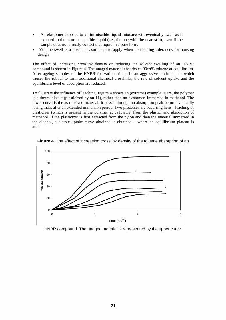
• An elastomer exposed to an immiscible liquid mixture will eventually swell as if exposed to the more compatible liquid (i.e., the one with the nearest δ), even if the sample does not directly contact that liquid in a pure form.
• Volume swell is a useful measurement to apply when considering tolerances for housing design.
The effect of increasing crosslink density on reducing the solvent swelling of an HNBR compound is shown in Figure 4. The unaged material absorbs ca 90wt% toluene at equilibrium. After ageing samples of the HNBR for various times in an aggressive environment, which causes the rubber to form additional chemical crosslinks; the rate of solvent uptake and the equilibrium level of absorption are reduced.
To illustrate the influence of leaching, Figure 4 shows an (extreme) example. Here, the polymer is a thermoplastic (plasticized nylon 11), rather than an elastomer, immersed in methanol. The lower curve is the as-received material; it passes through an absorption peak before eventually losing mass after an extended immersion period. Two processes are occurring here – leaching of plasticizer (which is present in the polymer at ca15wt%) from the plastic, and absorption of methanol. If the plasticizer is first extracted from the nylon and then the material immersed in the alcohol, a classic uptake curve obtained is obtained – where an equilibrium plateau is attained.
Figure 4 The effect of increasing crosslink density of the toluene absorption of an
%M
ass
upta
ke
100
80
60
40
20
0 0 1 2 3
Time (hrs1/2)
HNBR compound. The unaged material is represented by the upper curve.
21
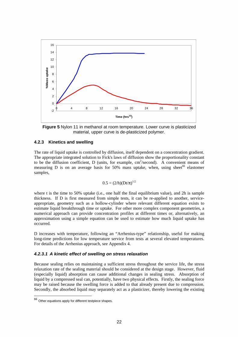
-2
0
2
4
6
8
10
12
14
16
0 4 8
( )
12 16 20 24 28 32 36
Time hrs1/2
%M
ass
upta
ke
Figure 5 Nylon 11 in methanol at room temperature. Lower curve is plasticized material, upper curve is de-plasticized polymer.
4.2.3 Kinetics and swelling
The rate of liquid uptake is controlled by diffusion, itself dependent on a concentration gradient. The appropriate integrated solution to Fick's laws of diffusion show the proportionality constant to be the diffusion coefficient, D (units, for example, cm2/second). A convenient means of measuring D is on an average basis for 50% mass uptake, when, using sheet66 elastomer samples,
1/20.5 = (2/h)(Dt/π)
where t is the time to 50% uptake (i.e., one half the final equilibrium value), and 2h is sample thickness. If D is first measured from simple tests, it can be re-applied to another, service-appropriate, geometry such as a hollow-cylinder where relevant different equation exists to estimate liquid breakthrough time or uptake. For other more complex component geometries, a numerical approach can provide concentration profiles at different times or, alternatively, an approximation using a simple equation can be used to estimate how much liquid uptake has occurred.
D increases with temperature, following an “Arrhenius-type” relationship, useful for making long-time predictions for low temperature service from tests at several elevated temperatures. For details of the Arrhenius approach, see Appendix 4.
4.2.3.1 A kinetic effect of swelling on stress relaxation
Because sealing relies on maintaining a sufficient stress throughout the service life, the stress relaxation rate of the sealing material should be considered at the design stage. However, fluid (especially liquid) absorption can cause additional changes in sealing stress. Absorption of liquid by a compressed seal can, potentially, have two physical effects. Firstly, the sealing force may be raised because the swelling force is added to that already present due to compression. Secondly, the absorbed liquid may separately act as a plasticizer, thereby lowering the existing
66 Other equations apply for different testpiece shapes.
22
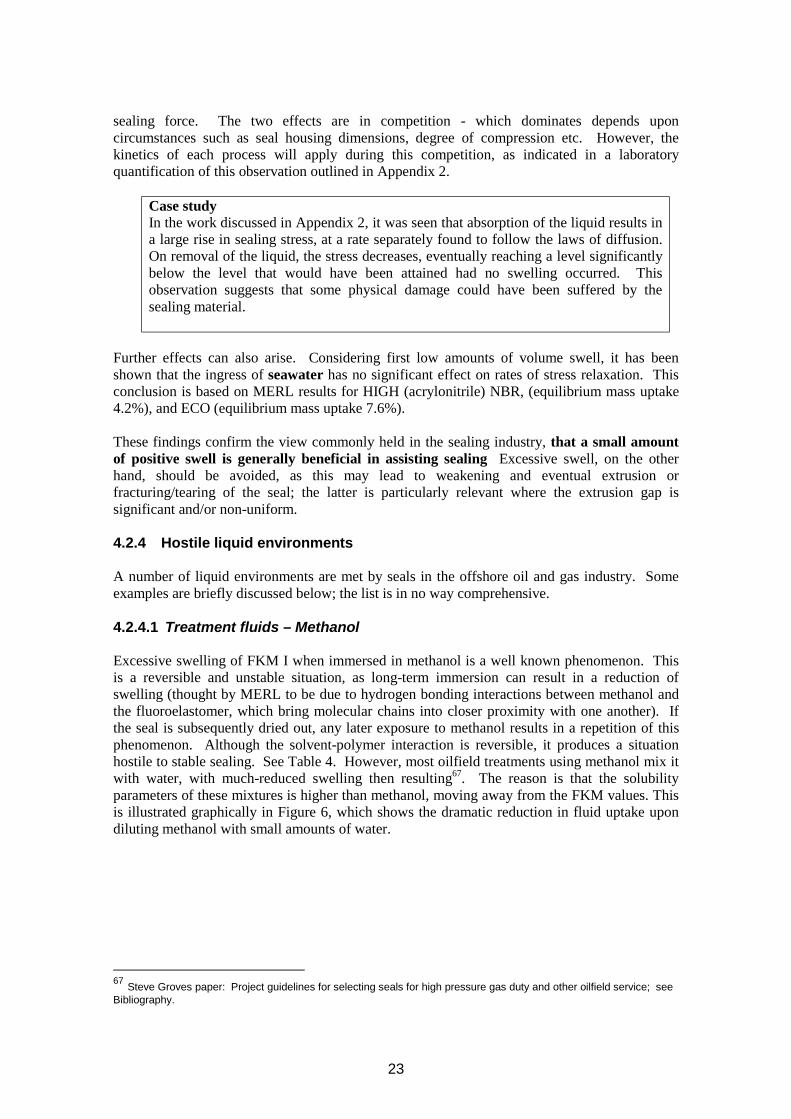
sealing force. The two effects are in competition - which dominates depends upon circumstances such as seal housing dimensions, degree of compression etc. However, the kinetics of each process will apply during this competition, as indicated in a laboratory quantification of this observation outlined in Appendix 2.
Case study In the work discussed in Appendix 2, it was seen that absorption of the liquid results in a large rise in sealing stress, at a rate separately found to follow the laws of diffusion. On removal of the liquid, the stress decreases, eventually reaching a level significantly below the level that would have been attained had no swelling occurred. This observation suggests that some physical damage could have been suffered by the sealing material.
Further effects can also arise. Considering first low amounts of volume swell, it has been shown that the ingress of seawater has no significant effect on rates of stress relaxation. This conclusion is based on MERL results for HIGH (acrylonitrile) NBR, (equilibrium mass uptake 4.2%), and ECO (equilibrium mass uptake 7.6%).
These findings confirm the view commonly held in the sealing industry, that a small amount of positive swell is generally beneficial in assisting sealing Excessive swell, on the other hand, should be avoided, as this may lead to weakening and eventual extrusion or fracturing/tearing of the seal; the latter is particularly relevant where the extrusion gap is significant and/or non-uniform.
4.2.4 Hostile liquid environments
A number of liquid environments are met by seals in the offshore oil and gas industry. Some examples are briefly discussed below; the list is in no way comprehensive.
4.2.4.1 Treatment fluids – Methanol
Excessive swelling of FKM I when immersed in methanol is a well known phenomenon. This is a reversible and unstable situation, as long-term immersion can result in a reduction of swelling (thought by MERL to be due to hydrogen bonding interactions between methanol and the fluoroelastomer, which bring molecular chains into closer proximity with one another). If the seal is subsequently dried out, any later exposure to methanol results in a repetition of this phenomenon. Although the solvent-polymer interaction is reversible, it produces a situation hostile to stable sealing. See Table 4. However, most oilfield treatments using methanol mix it with water, with much-reduced swelling then resulting67. The reason is that the solubility parameters of these mixtures is higher than methanol, moving away from the FKM values. This is illustrated graphically in Figure 6, which shows the dramatic reduction in fluid uptake upon diluting methanol with small amounts of water.
67 Steve Groves paper: Project guidelines for selecting seals for high pressure gas duty and other oilfield service; see Bibliography.
23
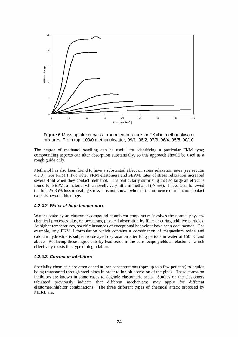
35
%M
ass
chan
ge
28
21
14
7
0 0 5 10 15 20 25 30 35 40
Root time (hrs1/2)
Figure 6 Mass uptake curves at room temperature for FKM in methanol/water mixtures. From top, 100/0 methanol/water, 99/1, 98/2, 97/3, 96/4, 95/5, 90/10.
The degree of methanol swelling can be useful for identifying a particular FKM type; compounding aspects can alter absorption substantially, so this approach should be used as a rough guide only.
Methanol has also been found to have a substantial effect on stress relaxation rates (see section 4.2.3). For FKM I, two other FKM elastomers and FEPM, rates of stress relaxation increased several-fold when they contact methanol. It is particularly surprising that so large an effect is found for FEPM, a material which swells very little in methanol (<<5%). These tests followed the first 25-35% loss in sealing stress; it is not known whether the influence of methanol contact extends beyond this range.
4.2.4.2 Water at high temperature
Water uptake by an elastomer compound at ambient temperature involves the normal physicochemical processes plus, on occasions, physical absorption by filler or curing additive particles. At higher temperatures, specific instances of exceptional behaviour have been documented. For example, any FKM I formulation which contains a combination of magnesium oxide and calcium hydroxide is subject to delayed degradation after long periods in water at 150 °C and above. Replacing these ingredients by lead oxide in the cure recipe yields an elastomer which effectively resists this type of degradation.
4.2.4.3 Corrosion inhibitors
Speciality chemicals are often added at low concentrations (ppm up to a few per cent) to liquids being transported through steel pipes in order to inhibit corrosion of the pipes. These corrosion inhibitors are known in some cases to degrade elastomeric seals. Studies on the elastomers tabulated previously indicate that different mechanisms may apply for different elastomer/inhibitor combinations. The three different types of chemical attack proposed by MERL are:
24
• Ionic: attack by amines in sea water or other aqueous media (seen chiefly for HIGH NBR and HNBR), possibly involving the acrylonitrile group; high pH amines (high amine nos.) are the most hostile;
• Free radical: attack by these amines in either aqueous or hydrocarbon liquids (observed in FKM I);
• Less hostile attack by phosphate esters and other minor additives, observed generally.
The consequence of such chemical attack is a permanent reduction in elastomer property levels, with increased temperature increasing the rate of any degradative reactions. At worst (e.g., high pH amines and FKM I), the seal can disintegrate. However, effective corrosion inhibitors which are claimed not to attack elastomers are now commercially available. Their manufacturers can advise on choice of inhibitor for preventing corrosion in particular applications, especially at high temperatures. In seal selection, it should be remembered that FKM I, NBR, and HNBR are susceptible to high pH inhibitors. As always, the best defence against catastrophe is appropriate compatibility testing prior to service. Material suppliers have developed grades of fluoroelastomer which are resistant to high pH environments; for example, Viton ETP (DuPont Dow Elastomers).
The most common outcome of interaction between a sealing elastomer and a hostile chemical species is the formation of additional crosslinks within the elastomer structure; for example, FKM contacting high pH fluids at elevated temperatures, NBR exposed to amines or oxygen at high temperature. The elastomer stiffens and may eventually embrittle, with loss of material compromising sealing function. The opposite type of degradation involves breakdown of the elastomer network (chain scission), resulting in the softening of the material.
4.2.4.4 Well stimulation fluids – acids
Because an acid might chemically attack ingredients within the elastomer as well as, in some cases, the elastomer itself, it is recommended that verification data of a selected material’s compatibility in the acid is requested from the component supplier. If unavailable, service-realistic testing should be performed.
Acetic acid, formic acid and hydrochloric acid/hydrofluoric acid (HCl/HF) mixtures are the more commonly-used treatment acids used offshore. Regarding handling, avoiding splashing into eyes etc is the main issue with the first two types, as these are weak acids, but HCl/HF is highly corrosive to personnel as well as to metals etc; stoppered glass containers, suitably cushioned, should be used for transporting this acid mixture. Regarding procedures, one becoming popular offshore with such fluids is to localise the treatment to the relevant part of the well etc – which will minimise the number of seals etc liable to become in contact with these acids. Each of these acids can be resisted by some elastomers, but not all – and the combinations will vary. It is therefore strongly advisable to provide exact details of the acids to be used to the supplier, to check carefully that the specified elastomer seals etc are fit-for-purpose.
4.2.5 Summary of liquid effects on seal elastomers
• Liquids dissolve into the surface of an elastomer, with diffusion carrying them into the bulk polymer.
• Different elastomers and liquids have different solubility parameter values. • Maximum absorption of fluid by an elastomer depends on the difference in δ values;
the closer they are, the more likely is fluid absorption.
25
• Other factors such as glass transition temperature, filler loading, degree of crosslinking, and liquid viscosity also affect maximum concentration.
• Volume swell is important for housing tolerance considerations. • Dissolved fluids diffuse into the elastomer bulk over a period of time depending on
- the value of the diffusion coefficient (which depends on the fluid and the elastomer)
- the seal section and geometry.• Diffusion is driven by concentration gradient, not by pressure. • Liquid uptake by elastomers results in swell:
- swell < 20% by volume is not usually a problem in static applications- swell > 20% can result in:
* overfill of the seal housing groove * seal extrusion damage * extremely high stresses in the seal and in the housing* occasionally, metal components being fractured* progressive degradation, such as a loss in physical and mechanical properties.
• Leaching effects are usually more than compensated for by swelling - but note that the leaching of protective agents, for example, antioxidants, has a knock-on effect on durability.
• Methanol can be particularly hostile to some elastomers, but for physico-chemical reasons only.
• Corrosion inhibitors, especially those of high pH, can chemically degrade some elastomers. • A small degree of positive swell is beneficial for the retention of sealing force.
4.3 GAS INTERACTIONS WITH ELASTOMERS
• Gases dissolve into the surface of an elastomer (adsorption): - gas concentration at the surface is the product of the applied gas pressure (partial pressure of each gas in a mixture) and the solubility coefficient.
• Gases diffuse from the surface into the interior of the elastomer - the diffusion coefficient relates diffusion rate with concentration gradient. - diffusion of gases is ca 1-2 orders of magnitude faster than liquid diffusion.
• If geometrical considerations allow, gases will pass right through the elastomer by dissolving, diffusing, and evaporating. The combination of these processes is permeation.
• Diffusion and solubility coefficients, D and s, are evaluated from permeation measurements.
4.3.1 Gas permeation
In permeation through a sheet, a linear concentration gradient exists between the contact and exit surfaces. The flat sheet is therefore a convenient geometry for evaluating D and s. For the steady-state diffusion of adsorbed gas from one surface of a plane sheet of elastomer through to the other, integration of Fick's laws of diffusion gives
(1/A)(q/t) = D(c1 - c2 )/h
where gas volume q (at STP) diffuses across area A, and through thickness h, in time t. D is the diffusion coefficient and c1 and c2 are the initial (“high”) and final (“low”) concentrations. If P1 and P2 are the initial and final pressures, then from Henry's law
c1 = sP1 and c2 = sP2
26
where s is the solubility coefficient. If the product Ds is defined as Q, termed the permeation coefficient, combining the above equations gives the general permeation equation for a membrane:
(1/A) (q/t) = Q (P1 - P2)/h
Hence Q - numerically the permeation rate through a unit cube brought about by unit pressure difference - can be obtained experimentally from the linear plot for q/t (all other factors being known). D is measured separately, and equals h2/6τ, where τ is the time lag by which the steady state permeation back-extrapolated to zero permeation is delayed from the test-start origin. Once Q and D are quantified, s and c1 are obtained using the equations above.
One use for these equations when performing HP permeation testing is to find the best conditions (low concentration, high diffusion coefficient) for avoiding potential explosive decompression failure68. As an example, in a series of tests three elastomers (FKM II, FKM III and FEPM) showed equally high gas permeation rates. However, the high permeation rates of FKM II and FEPM are mainly the result of a high rate of diffusion, with their solubility coefficients (and thus concentration of dissolved gas) being relatively low. For FKM III the reverse is true. Hence for these three elastomers the lower potential for explosive decompression damage is associated with FKM II and FEPM, although other material factors can also contribute to the extent of damage. The final choice would depend on these other factors.
Other pointers associated with HP gas in elastomers: • If an elastomer is completely surrounded by gas, or if there is no exit route from the
seal housing, the high surface concentration will eventually be attained throughout the elastomer bulk: saturation will be achieved.
• Below its Critical Temperature, a gas can become a liquid at elevated pressures, and behave accordingly. Carbon dioxide often displays this phenomenon in applications below 31°C.
• Solubility parameter can become relevant for gases at high pressures, that is, when liquid-like densities are achieved.
• At high pressures, the dissolved gas volume (relative to STP) in a seal can be more than 100 times the volume of the seal, that is, the gas concentration is greater than 100 cm3 of gas per cm3 of elastomer.
• Consequently, since reducing pressure rapidly allows gas to come out of solution inside the elastomer,
- the original concentration/pressure balance no longer applies,- gas bubbles may form in the elastomer, causing internal fractures and/or surfaceblistering. This is “explosive decompression” - see later for details.
4.3.2 Pressure, time and temperature effects
It might be thought that, from Henry's law, the concentration adsorbed at the high pressure surface could be increased indefinitely by increasing pressure. This is not so. At high pressures, when gas densities approach liquid densities, the adsorbed concentration tends to a constant value (analogous to the equilibrium mass uptake for liquids). The solubility coefficient is no longer a constant, but decreases with increasing pressure. For example, during permeation through HIGH ACN NBR at 195°C, carbon dioxide reaches an equilibrium concentration in the region of 100 cm3 of gas per cm3 of elastomer at about 7000 psi.
68 Review, section 4.4
27
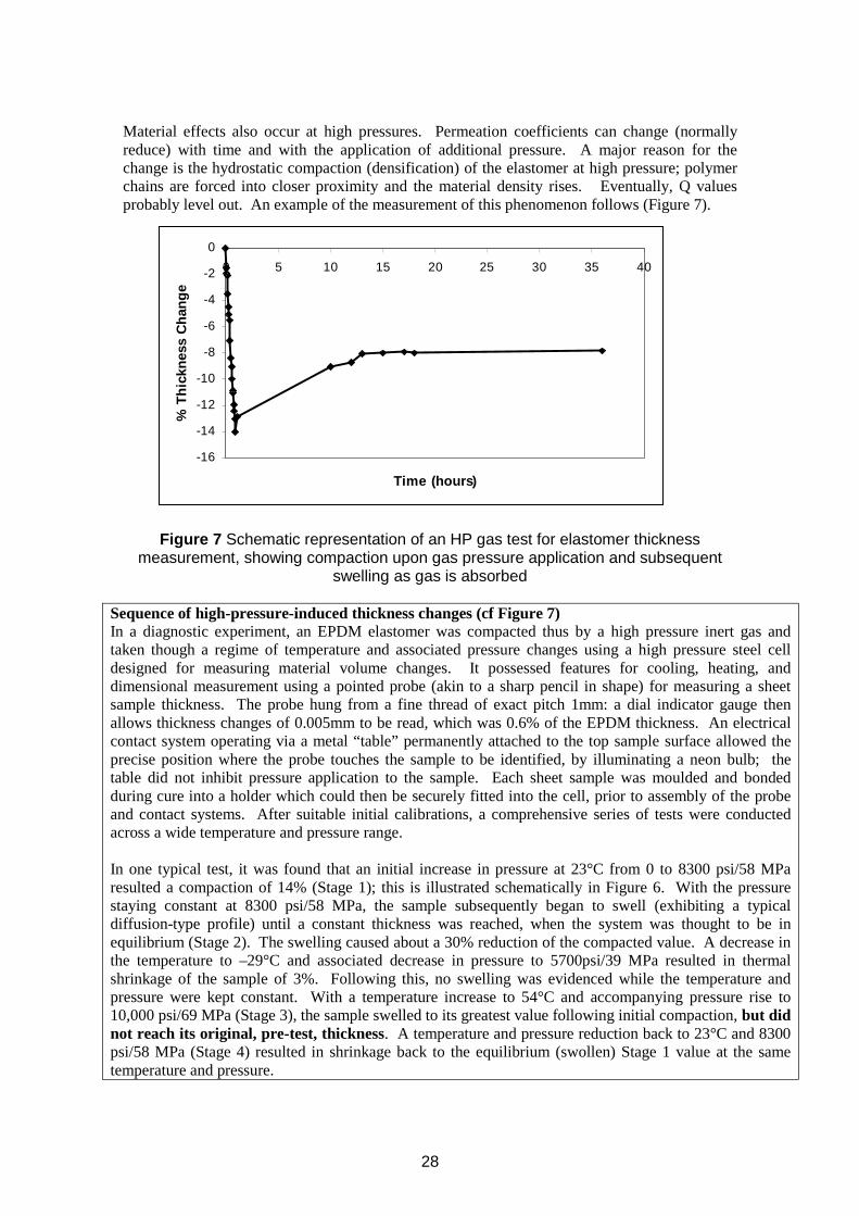
Material effects also occur at high pressures. Permeation coefficients can change (normally reduce) with time and with the application of additional pressure. A major reason for the change is the hydrostatic compaction (densification) of the elastomer at high pressure; polymer chains are forced into closer proximity and the material density rises. Eventually, Q values probably level out. An example of the measurement of this phenomenon follows (Figure 7).
-8
-6
-4
-2
0 0 5 10 20 30 40
( )
-16
-14
-12
-10
15 25 35
Time hours
% T
hick
ness
Cha
nge
Figure 7 Schematic representation of an HP gas test for elastomer thickness measurement, showing compaction upon gas pressure application and subsequent
swelling as gas is absorbed
Sequence of high-pressure-induced thickness changes (cf Figure 7) In a diagnostic experiment, an EPDM elastomer was compacted thus by a high pressure inert gas and taken though a regime of temperature and associated pressure changes using a high pressure steel cell designed for measuring material volume changes. It possessed features for cooling, heating, and dimensional measurement using a pointed probe (akin to a sharp pencil in shape) for measuring a sheet sample thickness. The probe hung from a fine thread of exact pitch 1mm: a dial indicator gauge then allows thickness changes of 0.005mm to be read, which was 0.6% of the EPDM thickness. An electrical contact system operating via a metal “table” permanently attached to the top sample surface allowed the precise position where the probe touches the sample to be identified, by illuminating a neon bulb; the table did not inhibit pressure application to the sample. Each sheet sample was moulded and bonded during cure into a holder which could then be securely fitted into the cell, prior to assembly of the probe and contact systems. After suitable initial calibrations, a comprehensive series of tests were conducted across a wide temperature and pressure range.
In one typical test, it was found that an initial increase in pressure at 23°C from 0 to 8300 psi/58 MPa resulted a compaction of 14% (Stage 1); this is illustrated schematically in Figure 6. With the pressure staying constant at 8300 psi/58 MPa, the sample subsequently began to swell (exhibiting a typical diffusion-type profile) until a constant thickness was reached, when the system was thought to be in equilibrium (Stage 2). The swelling caused about a 30% reduction of the compacted value. A decrease in the temperature to –29°C and associated decrease in pressure to 5700psi/39 MPa resulted in thermal shrinkage of the sample of 3%. Following this, no swelling was evidenced while the temperature and pressure were kept constant. With a temperature increase to 54°C and accompanying pressure rise to 10,000 psi/69 MPa (Stage 3), the sample swelled to its greatest value following initial compaction, but did not reach its original, pre-test, thickness. A temperature and pressure reduction back to 23°C and 8300 psi/58 MPa (Stage 4) resulted in shrinkage back to the equilibrium (swollen) Stage 1 value at the same temperature and pressure.
28
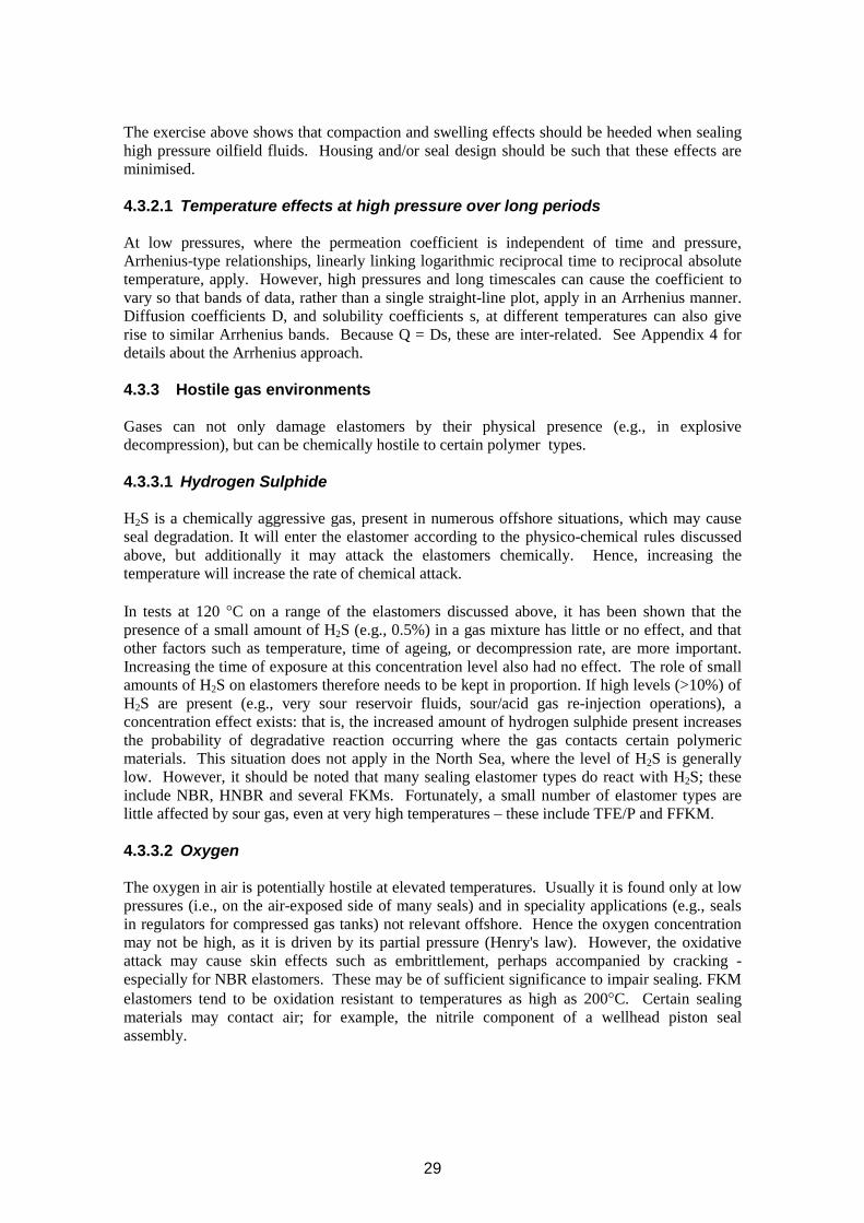
The exercise above shows that compaction and swelling effects should be heeded when sealing high pressure oilfield fluids. Housing and/or seal design should be such that these effects are minimised.
4.3.2.1 Temperature effects at high pressure over long periods
At low pressures, where the permeation coefficient is independent of time and pressure, Arrhenius-type relationships, linearly linking logarithmic reciprocal time to reciprocal absolute temperature, apply. However, high pressures and long timescales can cause the coefficient to vary so that bands of data, rather than a single straight-line plot, apply in an Arrhenius manner. Diffusion coefficients D, and solubility coefficients s, at different temperatures can also give rise to similar Arrhenius bands. Because Q = Ds, these are inter-related. See Appendix 4 for details about the Arrhenius approach.
4.3.3 Hostile gas environments
Gases can not only damage elastomers by their physical presence (e.g., in explosive decompression), but can be chemically hostile to certain polymer types.
4.3.3.1 Hydrogen Sulphide
H2S is a chemically aggressive gas, present in numerous offshore situations, which may cause seal degradation. It will enter the elastomer according to the physico-chemical rules discussed above, but additionally it may attack the elastomers chemically. Hence, increasing the temperature will increase the rate of chemical attack.
In tests at 120 °C on a range of the elastomers discussed above, it has been shown that the presence of a small amount of H2S (e.g., 0.5%) in a gas mixture has little or no effect, and that other factors such as temperature, time of ageing, or decompression rate, are more important. Increasing the time of exposure at this concentration level also had no effect. The role of small amounts of H2S on elastomers therefore needs to be kept in proportion. If high levels (>10%) of H2S are present (e.g., very sour reservoir fluids, sour/acid gas re-injection operations), a concentration effect exists: that is, the increased amount of hydrogen sulphide present increases the probability of degradative reaction occurring where the gas contacts certain polymeric materials. This situation does not apply in the North Sea, where the level of H2S is generally low. However, it should be noted that many sealing elastomer types do react with H2S; these include NBR, HNBR and several FKMs. Fortunately, a small number of elastomer types are little affected by sour gas, even at very high temperatures – these include TFE/P and FFKM.
4.3.3.2 Oxygen
The oxygen in air is potentially hostile at elevated temperatures. Usually it is found only at low pressures (i.e., on the air-exposed side of many seals) and in speciality applications (e.g., seals in regulators for compressed gas tanks) not relevant offshore. Hence the oxygen concentration may not be high, as it is driven by its partial pressure (Henry's law). However, the oxidative attack may cause skin effects such as embrittlement, perhaps accompanied by cracking especially for NBR elastomers. These may be of sufficient significance to impair sealing. FKM elastomers tend to be oxidation resistant to temperatures as high as 200°C. Certain sealing materials may contact air; for example, the nitrile component of a wellhead piston seal assembly.
29
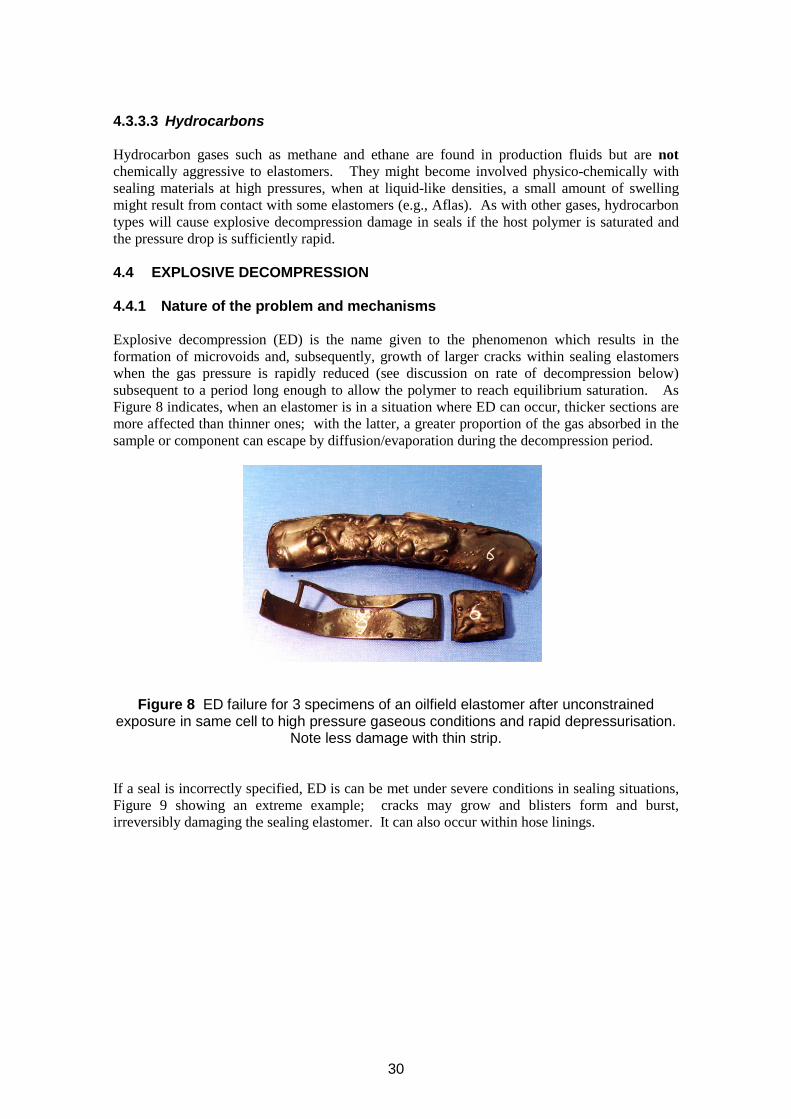
4.3.3.3 Hydrocarbons
Hydrocarbon gases such as methane and ethane are found in production fluids but are not chemically aggressive to elastomers. They might become involved physico-chemically with sealing materials at high pressures, when at liquid-like densities, a small amount of swelling might result from contact with some elastomers (e.g., Aflas). As with other gases, hydrocarbon types will cause explosive decompression damage in seals if the host polymer is saturated and the pressure drop is sufficiently rapid.
4.4 EXPLOSIVE DECOMPRESSION
4.4.1 Nature of the problem and mechanisms
Explosive decompression (ED) is the name given to the phenomenon which results in the formation of microvoids and, subsequently, growth of larger cracks within sealing elastomers when the gas pressure is rapidly reduced (see discussion on rate of decompression below) subsequent to a period long enough to allow the polymer to reach equilibrium saturation. As Figure 8 indicates, when an elastomer is in a situation where ED can occur, thicker sections are more affected than thinner ones; with the latter, a greater proportion of the gas absorbed in the sample or component can escape by diffusion/evaporation during the decompression period.
Figure 8 ED failure for 3 specimens of an oilfield elastomer after unconstrained exposure in same cell to high pressure gaseous conditions and rapid depressurisation.
Note less damage with thin strip.
If a seal is incorrectly specified, ED is can be met under severe conditions in sealing situations, Figure 9 showing an extreme example; cracks may grow and blisters form and burst, irreversibly damaging the sealing elastomer. It can also occur within hose linings.
30
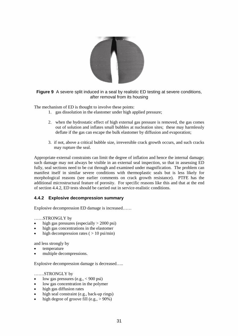
Figure 9 A severe split induced in a seal by realistic ED testing at severe conditions, after removal from its housing
The mechanism of ED is thought to involve these points: 1. gas dissolution in the elastomer under high applied pressure;
2. when the hydrostatic effect of high external gas pressure is removed, the gas comes out of solution and inflates small bubbles at nucleation sites; these may harmlessly deflate if the gas can escape the bulk elastomer by diffusion and evaporation;
3. if not, above a critical bubble size, irreversible crack growth occurs, and such cracks may rupture the seal.
Appropriate external constraints can limit the degree of inflation and hence the internal damage; such damage may not always be visible in an external seal inspection, so that in assessing ED fully, seal sections need to be cut through and examined under magnification. The problem can manifest itself in similar severe conditions with thermoplastic seals but is less likely for morphological reasons (see earlier comments on crack growth resistance). PTFE has the additional microstructural feature of porosity. For specific reasons like this and that at the end of section 4.4.2, ED tests should be carried out in service-realistic conditions.
4.4.2 Explosive decompression summary
Explosive decompression ED damage is increased……
……STRONGLY by • high gas pressures (especially > 2000 psi) • high gas concentrations in the elastomer • high decompression rates ( > 10 psi/min)
and less strongly by • temperature • multiple decompressions.
Explosive decompression damage is decreased…..
…….STRONGLY by • low gas pressures (e.g., < 900 psi) • low gas concentration in the polymer • high gas diffusion rates • high seal constraint (e.g., back-up rings) • high degree of groove fill (e.g., > 90%)
31
• slow decompression rates (> 5 days)
and less strongly by • high elastic modulus (but individual cracks may be larger if failure does occur) • high rubber tear strength. (these increasing with decreasing temperature).
Note Because concentration is a large factor in bringing about ED-induced fractures, accelerated tests should not take the approach of using CO2 as test gas instead of a service gas. The very high concentration of CO2 in elastomers means that the “ acceleration” brings about failures that probably will not arise at all with the service gas. Any acceleration is best brought about by using elevated pressures and temperature changes as appropriate to speed up the time to saturate the elastomer prior to the decompression stage. Similarly, correct housings should be employed to constrain the seals during testing as, during service, these provide support in resisting ED failure, in effect by increasing the elastomer’s modulus; if tested unconstrained, the lack of this support is a departure from service-reality.
As a caveat, it should be noted that extrapolation of test results is not yet possible with ED; that is, performance at low pressure/small seal section/high temperature cannot be used to indicate performance at high pressure/large seal section/low temperature. Qualification testing at (or close to) service conditions is desirable. However, for thick section seals, time aspects of the gas absorption stage can be accelerated if values of all permeation-related coefficients for the system are known.
4.5 LIFE PREDICTION TECHNIQUE
For applications with components exposed to fluids where design criteria are used to set limits the criteria being based on a property which will change with time for a service-related reason then residual life becomes zero when one or the other limit is reached. Service life prediction is ideally based on predicting when this stage is reached. One caveat required that a prediction based on a selected property assumes no other failure mechanism becomes dominant instead during service.
Example For instance, a seal may have a 10 year life from a prediction based on stress relaxation or stiffness changes, but if it is unexpectedly exposed to the explosive decompression phenomenon it could suffer damage and fail immediately. All possibilities must be considered, and the determining factor identified for all stages of service life.
At constant temperature, if laboratory testing can be performed for the full service life, then the response of a critical property (e.g. modulus, stiffness) for an elastomer to, for instance, exposure to a particular fluid can be checked in full before the application is started. In addition with unchanging temperature, the behaviour of properties such as stress relaxation which follow well established rules can be extrapolated with confidence to much beyond testing times (care only being taken that the relative contributions of physical and chemical stress relaxation have been properly resolved). The complications introduced where temperatures can vary are considered later.
Empirical extrapolation of other properties to longer service times at one temperature is possible if a clear pattern is established for the property level (or its logarithm) against time, but any associated competing chemical reactions can cause some confusion in these patterns.
32

As increases in temperature cause increases in reaction rates, a means of conducting laboratory testing at temperatures well above service temperature (provided no transition or degradation temperature is surpassed) is highly desirable. These can be empirical; however, a more reasoned approach can also be possible, the “Arrhenius approach” being detailed in Appendix 4.
A warning - it should be noted that, if the upper service temperature is high (e.g. 180 °C), the scope for timely acceleration is reduced using thermal means. Experience may then be a factor in making judgement about likely performance, (e.g. by using an increase in concentration instead).
33

34
5 QA/QC
QA/QC is only treated in outline here. For Quality Assurance (QA), the purchaser should obtain from the supplier technical evidence that the materials selected will meet specification. This information should be in the form of appropriate mechanical and fluid resistance (compatibility) data, ideally including ageing information and, for high pressure gas applications, explosion decompression results from service-realistic testing procedures (or, failing that, well-established Standard tests). More detail is provided when discussing the Standard test methods that can be employed for obtaining this information (see section 7, and Table 1).
Regarding Quality Control (QC), ideally, the purchaser will obtain as a minimum from each batch of seal products a typical hardness value obtained from five seals chosen at random, and a copy of a test plot from a curemeter showing that the cure characteristics of the batch are within prescribed limits. Ideally, other data for specific behaviour relevant to particular applications could be included – e.g. from methanol absorption testing if FKM seals are to be located in service such that they may be exposed to methanol treatments.
35

36
6 SEAL FAILURE
(Further to the comments in Guidelines sections 2.2. and 2.3.)
Material deterioration (physical or chemical) can bring about failure of its own accord, or can weaken the elastomer so that other factors manifest themselves more easily. As an example of the first statement, explosive decompression fracture (section 4.4) - if reaching right through the seal - could easily lead to significant or drastic leakage; regarding the second point, liquid absorption with associated swelling and weakening (section 4.2) can increase the rate of extrusion damage. However, other less dramatic forms of failure are possible, as discussed below.
6.1 SEAL LEAKAGE MODES
Basically, a sealing system functions successfully for its full service life (the most likely case if design and material selection points are correct) or it fails by allowing leakage – at some rate between the extremes of seepage or catastrophic failure.
Clearly if a seal is damaged for whatever reason, leakage might occur, perhaps at a considerable rate. However, the more fundamental modes of leakage are (largest first): • fluid flow between a seal and its steel counterface through lack of sealing force between the
seal and the counterface • molecular diffusion through the body of the material – one part of the permeation
phenomenon • molecular diffusion along the interface between seal and counterface.
The first mode is usually the important one. In applications at high pressure the second mode may be sufficiently significant that it should be allowed for; however, in a particular HP test comparison performed at MERL, appropriate measurements led to the estimation that gas permeation rate was at most 2% of the rate of the smallest leak that could be measured. If there is good contact, then the third mode is unlikely to be significant. Only first mode leakage is considered for the remainder of this section.
Leakage can arise from deficiencies in design, housing or seal manufacture, or operational factors.
6.2 DESIGN, MANUFACTURING AND OPERATIONAL FACTORS IN LEAKAGE
6.2.1 Design factors
If poor design allows excessive deflections of the supporting structure, the housings can be stretched outside tolerance as a result, in the worst case thus allowing leakage. If the design requires anti-extrusion rings, these can be solid or spiral. A spiral ring can be made of PTFE or some other flexible material, and they are easy to fit on a housing containing permanently-machined grooves and rims. When the seal is activated, the step in the back-up ring disappears, to give essentially a flat profile. Solid anti-extrusion rings are more reliable under more extreme conditions, but can only be fitted if the design is such that the housing has one rim only (on the low pressure side) or if any high pressure-side rim is removable (probably threaded).
The use of seal stacks, outlined previously, is based on the concept that, if the first set of seals fails, the following sets in the sequence will continue the overall sealing; however, the
37
following important question needs to be answered in resolving whether this indeed is the case. If the first set initially operates successfully but then leaks, does its presence allow the second set to energise properly when called upon to do so?
6.2.2 Housing factors and seal quality
Housing-manufacturing quality and seal manufacturing issues are also factors. A poorly located O-ring can allow leakage, for instance, due to the inner shaft’s not being located centrally, or an off-centre housing. Properly applied QA and QC procedures applied to the seal manufacture should mean that seals are of the correctly-specified material type, cured to the correct degree, with no flaws or weaknesses.
6.2.3 Seal damage during installation
Installation should be conducted with care, to avoid damaging seal and/or housing - clearly, any such damage might increase any leakage rate, either initially or later in the seal’s life. Specifically, overstretching or cutting the seal, scratching the housing, or scoring the rim could all lead to unpredictable leakage.
6.2.4 Loss of sealing force (stress relaxation or thermal effects)
The loss of sealing stress by the process of stress relaxation (section 3.4.2 and Appendix 2) should not lead to complete loss of sealing stress providing that correct design and material choice has been made. Laboratory test methods for measuring this property’s magnitudes exist (Appendix 2). However, it is strongly suspected that absolute predictions are not yet possible – there are too many variables which could change relaxation rate (Appendix 2). Relative material performance can be obtained by the laboratory testing - the ranking obtained should be used to select the best material. Then selection material will also be very strongly dependent on experience. Using back-up rings will help resist stress relaxation.
Thermal effects are threefold: • influence on stress relaxation • thermal shrinkage/expansion • cooling through Tg.
The first two effects are discussed briefly in Appendix 2. The variations arising from the first can be significant, being one reason why the time to reach a complete loss of sealing stress by this ongoing fundamental time-dependent property is difficult to predict.
Regarding the second, the coefficients of expansion of elastomers vary by perhaps 50% between different elastomers, but more importantly, as a class elastomers possess coefficients 10x greater than that of steel. Hence, if extreme temperature decreases occur, a seal in a badly-designed housing could become too small for the groove – thus clearly losing sealing stress. An increase in temperature could enhance the likelihood of extrusion taking place – especially if a high groove-fill is used (for instance, to combat the possibility of ED damage).
If the temperature change on cooling passes through the Tg of the elastomer, it will become glassy as well as shrink, and could well lose sealing force in this state. Even if re-warmed, a compression set feature might apply, the elastomer (remembering its compressed configuration, so that once again being prone to leakage).
38
6.2.5 Extrusion
Extrusion may lead to fracture, because of the stress concentration where the seal comes into contact with the sharp edge of the housing; if the fracture is large enough, leakage can result. However, there is a ‘Catch 22’ situation, as excessive rounding of this edge to reduce the stress concentration and hence the possibility of fracture may have the effect of making extrusion easier! Using back-up rings will help resist extrusion by limiting access to the extrusion gap.
6.2.6 ED with HP gas
ED will only take place in a fluid with gas present after a depressurisation, probably a rather rapid one. This form of fracture is discussed in section 4.4. As cracks and blisters can arise if it occurs, clearly seal leakage can follow.
6.2.7 Fluid swelling (mainly liquids)
Swelling can occur in circumstances covered in section 4.2, or if the seal material is constrained, the associated build-up of stress is outlined in Appendix 2. Excessive swelling can lead to a weakening of the material allowing fracture/tear or failure by extrusion.
6.2.8 Chemical ageing
Chemical attack due to mechanisms such as those discussed throughout sections 4.2 and 4.3 can result in failure due to specifications being exceeded or, more randomly, to eventual material failure such as surface embrittlement with associated cracking or crumbling.
39

40
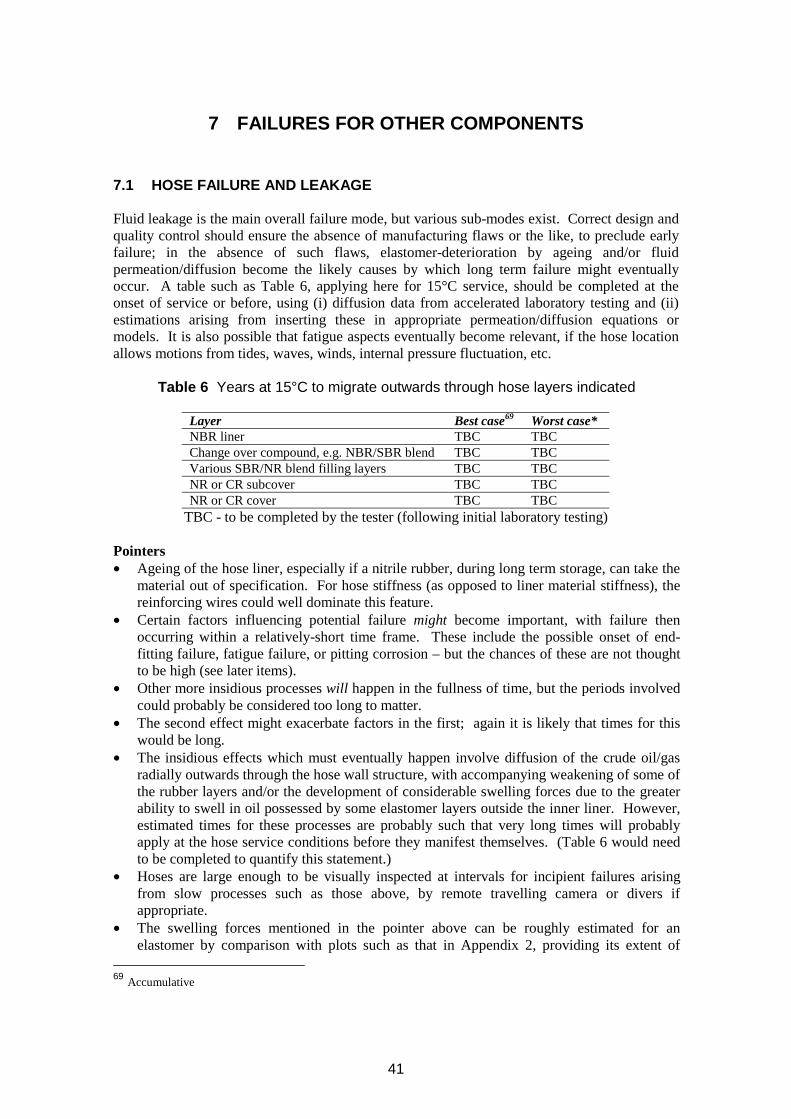
7 FAILURES FOR OTHER COMPONENTS
7.1 HOSE FAILURE AND LEAKAGE
Fluid leakage is the main overall failure mode, but various sub-modes exist. Correct design and quality control should ensure the absence of manufacturing flaws or the like, to preclude early failure; in the absence of such flaws, elastomer-deterioration by ageing and/or fluid permeation/diffusion become the likely causes by which long term failure might eventually occur. A table such as Table 6, applying here for 15°C service, should be completed at the onset of service or before, using (i) diffusion data from accelerated laboratory testing and (ii) estimations arising from inserting these in appropriate permeation/diffusion equations or models. It is also possible that fatigue aspects eventually become relevant, if the hose location allows motions from tides, waves, winds, internal pressure fluctuation, etc.
Table 6 Years at 15°C to migrate outwards through hose layers indicated
Layer Best case69 Worst case* NBR liner TBC TBC Change over compound, e.g. NBR/SBR blend TBC TBC Various SBR/NR blend filling layers TBC TBC NR or CR subcover TBC TBC NR or CR cover TBC TBC
TBC - to be completed by the tester (following initial laboratory testing)
Pointers • Ageing of the hose liner, especially if a nitrile rubber, during long term storage, can take the
material out of specification. For hose stiffness (as opposed to liner material stiffness), the reinforcing wires could well dominate this feature.
• Certain factors influencing potential failure might become important, with failure then occurring within a relatively-short time frame. These include the possible onset of end-fitting failure, fatigue failure, or pitting corrosion – but the chances of these are not thought to be high (see later items).
• Other more insidious processes will happen in the fullness of time, but the periods involved could probably be considered too long to matter.
• The second effect might exacerbate factors in the first; again it is likely that times for this would be long.
• The insidious effects which must eventually happen involve diffusion of the crude oil/gas radially outwards through the hose wall structure, with accompanying weakening of some of the rubber layers and/or the development of considerable swelling forces due to the greater ability to swell in oil possessed by some elastomer layers outside the inner liner. However, estimated times for these processes are probably such that very long times will probably apply at the hose service conditions before they manifest themselves. (Table 6 would need to be completed to quantify this statement.)
• Hoses are large enough to be visually inspected at intervals for incipient failures arising from slow processes such as those above, by remote travelling camera or divers if appropriate.
• The swelling forces mentioned in the pointer above can be roughly estimated for an elastomer by comparison with plots such as that in Appendix 2, providing its extent of
69 Accumulative
41
unconstrained swelling is known from simple laboratory test work. Such plots can be established for different elastomers; MERL has such data for several oilfield elastomer types.
• However, it is unlikely that swelling forces will become high enough to be important for some years longer than the times estimated in the summary table above, which is based solely on times to reach the various regions by the liquid diffusion process. Swelling will have its own slower time frame.
• Fatigue aspects could also apply if continual movements are associated with the hose service. Unless these conditions are severe, fatigue onset will probably be far off – it cannot be quantified; one factor which could affect this is if diffusion to outer hose regions cause rubber deterioration which allows crack initiation to occur. However, from the pointers above, long times would be expected before this occurred.
• Fatigue could also make an existing crack (split) grow, but regular inspections should monitor its rate It is unlikely to grow uncontrollably between inspections of once or twice a year.
• It is thought that end-fitting debonding issues are not likely to be great. The bonded interfacial region is thin (tens of micrometres) so that it displays only a tiny cross-sectional area to crude oil internally and sea water externally. Hence only very small amounts of liquid would be able to diffuse into the dried cured adhesive at the interface. Because of the hugely-greater liner inner surface area, more oil would enter liner regions near the end-fittings to cause swelling if sufficiently unconstrained; as these regions must be heavily constrained, being compressed by the tightly-wrapped end-fitting holding (fixing) wires, this attempted swelling will transpose to an associated swelling force which would realistically acting radially inwards. This would lead to a compression of the interfacial adhesive region, which would inhibit potential failure modes. It is not thought that the rubber-to-steel adhesive interface is a likely failure path.
• Repeated inspections (annually or more frequent) are recommended to observe whether cracks are initiated or if there is evidence of hose swelling; inspection at the end-fitting can reassure on the debonding point above. (The possibility of whether a permanent painted grid is possible on the hose to assist in these assessments can be considered.)
Sea water is not seen as a general hazard, as it causes minimal elastomer deterioration throughout. However, if the existing split provides a short-cut route of seawater to the embedded support wires, pitting corrosion is a possibility. Hence special inspection should be made of any existing split region (if relevant), to include checking for local swelling, evidence of rust etc.
7.2 FLEXIBLE JOINTS
For these components (see section 2.3), as well as the types of failures evidenced by elastomers used as seals, elastomer-to-metal debonding can again be an issue to resolve at the design and QA stage. Fatigue issues can also be important, as the application is a dynamic one.
7.3 DELUGE SLEEVE VALVE DIAPHRAGMS
Deluge sleeves (section 2.3) during development in their original form initially exhibited fatigue failures brought about by a monthly testing routine demanded by the end-users to gain confidence they would function if called upon in the event of a potential disaster. A material
42
development and change solved this problem. This is an unusual situation where the failure was actually brought about by the QA testing deemed necessary to ensure that a component would function whenever called upon to do so.
7.4 ROOT CAUSE ANALYSIS FOR COMPONENT- FAILURE GENERALLY
If a failure incident occurs, root cause analysis (RCA) can be used to identify the most basic cause. If this cause is within management control, then steps can be taken to control it. If the cause is design, then a re-design may be the only option. RCA will involve a sequence of defining the problem and collecting data, charting events and causal factors, identifying the critical or direct causes, and the root causes from which effective solutions can be identified and implemented. Barriers to avoid unwanted outcomes may also need to be reviewed. A variety of techniques is available for RCA, detailed description of which is beyond the scope of this document. The following is a discussion of the specific aspects that may need to be considered as part of an RCA of an incident involving elastomeric materials and components used offshore.
7.4.1 Gathering data
At this stage as much information as possible is required as input to the later stages. Things to be considered include: • the history of the conditions that the component has experienced – including storage,
installation and operation (e.g. temperatures, pressures, pressure changes, fluids, UV, ozone levels, exceptional weather or storm events etc)
• details of the design specifications • details of the design and materials selected and the methodology employed • details of design verification and performance verification and validation • quality records relating to the manufacture of the component and factory acceptance
(traceability of the rubber component should go back to the manufacturers moulding records)
• procedures for transportation, installation and installation records • maintenance and inspection procedures and records • previous or similar incidents • examination/analysis of failed components/material (see Guidelines section 9).
7.4.2 Barriers
Barriers to prevent incidents will be in place as part of work-place precautions and a risk control system. Barriers are not only physical, but will also include documentation and procedures involving: • design review • design verification and validation studies • risk assessment • quality assurance and inspection • preventative maintenance • training and supervision etc.
7.4.3 Charting events and causal factors
As part of an investigation, a sequence diagram that charts all the events chronologically, together with their relationships, is produced. Generally, this will include equipment, personnel and other factors, e.g. natural phenomena such as storms. Failure of a barrier can be a causal
43
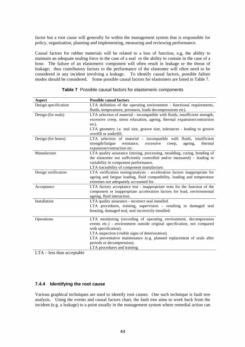
factor but a root cause will generally lie within the management system that is responsible for policy, organisation, planning and implementing, measuring and reviewing performance.
Causal factors for rubber materials will be related to a loss of function, e,g, the ability to maintain an adequate sealing force in the case of a seal or the ability to contain in the case of a hose. The failure of an elastomeric component will often result in leakage or the threat of leakage; thus contributory factors to the performance of the elastomer will often need to be considered in any incident involving a leakage. To identify causal factors, possible failure modes should be considered. Some possible causal factors for elastomers are listed in Table 7.
Table 7 Possible causal factors for elastomeric components
Aspect Possible causal factors Design specification LTA definition of the operating environment - functional requirements,
fluids, temperatures, pressures, loads decompressions etc). Design (for seals) LTA selection of material - incompatible with fluids, insufficient strength,
excessive creep, stress relaxation, ageing, thermal expansion/contraction etc). LTA geometry i.e. seal size, groove size, tolerances - leading to groove overfill or underfill.
Design (for hoses) LTA selection of material - incompatible with fluids, insufficient strength/fatigue resistance, excessive creep, ageing, thermal expansion/contraction etc.
Manufacture LTA quality assurance (mixing, processing, moulding, curing, bonding of the elastomer not sufficiently controlled and/or measured) – leading to variability in component performance. LTA traceability of component manufacture.
Design verification LTA verification testing/analysis - acceleration factors inappropriate for ageing and fatigue loading, fluid compatibility, loading and temperature extremes not adequately accounted for.
Acceptance LTA factory acceptance test - inappropriate tests for the function of the component or inappropriate acceleration factors for load, environmental ageing, fluid interaction.
Installation LTA quality assurance - incorrect seal installed. LTA procedures, training, supervision – resulting in damaged seal housing, damaged seal, seal incorrectly installed.
Operations LTA monitoring (recording of operating environment, decompression events etc.) - environment outside original specification, not compared with specification). LTA inspection (visible signs of deterioration). LTA preventative maintenance (e.g. planned replacement of seals after periods or decompression). LTA procedures and training.
LTA – less than acceptable
7.4.4 Identifying the root cause
Various graphical techniques are used to identify root causes. One such technique is fault tree analysis. Using the events and causal factors chart, the fault tree aims to work back from the incident (e.g. a leakage) to a point usually in the management system where remedial action can
44
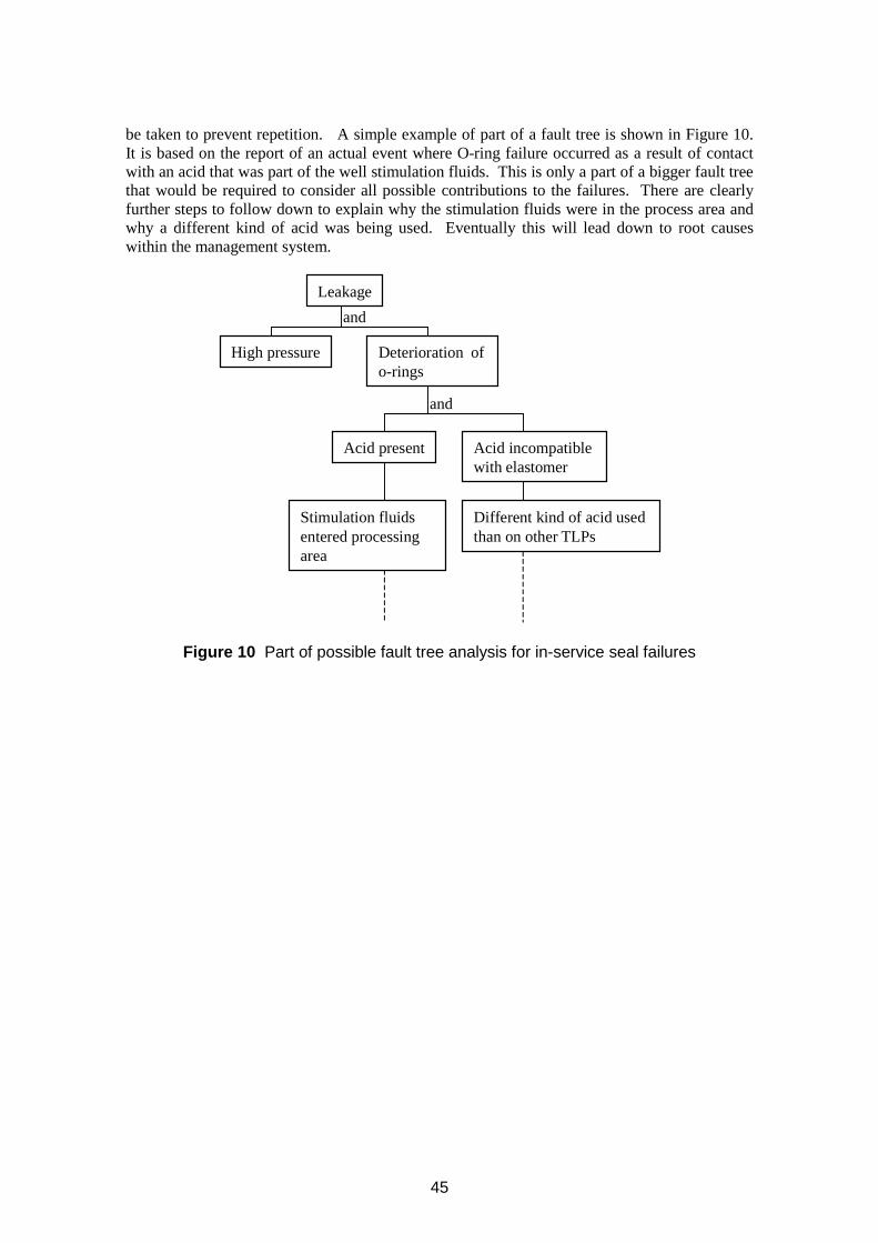
be taken to prevent repetition. A simple example of part of a fault tree is shown in Figure 10. It is based on the report of an actual event where O-ring failure occurred as a result of contact with an acid that was part of the well stimulation fluids. This is only a part of a bigger fault tree that would be required to consider all possible contributions to the failures. There are clearly further steps to follow down to explain why the stimulation fluids were in the process area and why a different kind of acid was being used. Eventually this will lead down to root causes within the management system.
o-rings
and
and
Leakage
Deterioration of
Acid present Acid incompatible with elastomer
High pressure
Stimulation fluids entered processing area
Different kind of acid used than on other TLPs
Figure 10 Part of possible fault tree analysis for in-service seal failures
45

46
8 INDUSTRY STANDARDS
Tables and comments showing the designation of Standards concerning coding of elastomer types, appropriate general mechanical properties, and chemical analysis to identify most aspects about elastomers, are given in sections 3.4.3, 3.4.1 and 3.4.6 respectively. The comments below address other Standards associated with elastomeric component upstream O&G performance.
Ageing behaviour is followed by observing changes in mechanical properties such as tensile modulus and other tensile properties, compression set, tear strength (see Table 1).
8.1 NORSOK M-710 REV 2
This specific Standard for seals is designed to qualify “critical non-metallic (polymer) sealing, seal and back-up materials for permanent use subsea” by addressing two aspects of performance – chemical ageing and rapid gas decompression (RGD) resistance. NORSOK Standards are administered and issued by the Norwegian Technology Centre.
For elastomers, the relevant sections of the Standard are 7.2 (and Annex A) and 7.3 (and Annex B). The first provides guidance for evaluating chemical (including sour) ageing of elastomers, the second to assess their resistance to rapid gas decompression (RGD) (or ED) events – testing being conducted with housing jigs which constrain the seals in a service-realistic manner. Clearly, the RGD test is only applicable if the seals contact pressurised gas during service. For thermoplastics, only chemical ageing is listed (section 8 and Annex C in the Standard).
For the most part, NORSOK M-710 rev. 2 allows specimens and test conditions to be selected which are service-relevant for primary seals, including the model test liquids to be used. For sealing applications involving high pressure gas, it is crucial to replicate service conditions as closely as possible when qualifying elastomers. However, NORSOK is rather restrictive about the choice of gas mixtures that can be used in RGD testing. Findings from this work should probably be tempered with regard to secondary seal situations as here, in practice, fluid conditions at the seal will not reach the severity of the well conditions until primary seal failure.
Hence, NORSOK M-710 is highly relevant, although it is not perfect.
8.1.1 Detailed comments
The key word in this Standard is “shall”, defined in section 3.1 as follows:
“Verbal form used to indicate requirements strictly to be followed in order to conform to the Standard and from which no deviation is permitted, unless accepted by all involved parties.”
This means, for instance, that other O-ring sizes from the BS300 series, such as BS312, could, with mutual agreement between interested parties, be used if a suitable argument for this change could be made: for instance, valve seals may have thicker section than the 5.33 mm of the BS300 series. In RGD testing at blowdown, O-ring section diameter governs gas diffusion rate out of the seal, and the related housing geometry will govern how much reinforcement is applied to the seal, to bolster elastomer strength levels. Hence, results should be the same after testing any BS300 series O-ring, all other factors (temperature, pressure, blowdown rate, etc) being the same.
47
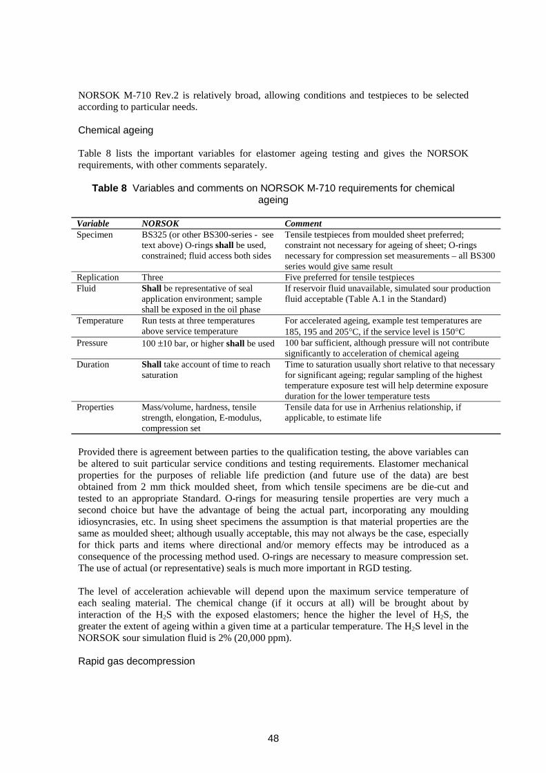
NORSOK M-710 Rev.2 is relatively broad, allowing conditions and testpieces to be selected according to particular needs.
Chemical ageing
Table 8 lists the important variables for elastomer ageing testing and gives the NORSOK requirements, with other comments separately.
Table 8 Variables and comments on NORSOK M-710 requirements for chemical ageing
Variable NORSOK Comment Specimen BS325 (or other BS300-series - see Tensile testpieces from moulded sheet preferred;
text above) O-rings shall be used, constraint not necessary for ageing of sheet; O-rings constrained; fluid access both sides necessary for compression set measurements – all BS300
series would give same result Replication Three Five preferred for tensile testpieces Fluid Shall be representative of seal If reservoir fluid unavailable, simulated sour production
application environment; sample fluid acceptable (Table A.1 in the Standard) shall be exposed in the oil phase
Temperature Run tests at three temperatures For accelerated ageing, example test temperatures are above service temperature 185, 195 and 205°C, if the service level is 150°C
Pressure 100 ±10 bar, or higher shall be used 100 bar sufficient, although pressure will not contribute significantly to acceleration of chemical ageing
Duration Shall take account of time to reach saturation
Time to saturation usually short relative to that necessary for significant ageing; regular sampling of the highest temperature exposure test will help determine exposure duration for the lower temperature tests
Properties Mass/volume, hardness, tensile strength, elongation, E-modulus, compression set
Tensile data for use in Arrhenius relationship, if applicable, to estimate life
Provided there is agreement between parties to the qualification testing, the above variables can be altered to suit particular service conditions and testing requirements. Elastomer mechanical properties for the purposes of reliable life prediction (and future use of the data) are best obtained from 2 mm thick moulded sheet, from which tensile specimens are be die-cut and tested to an appropriate Standard. O-rings for measuring tensile properties are very much a second choice but have the advantage of being the actual part, incorporating any moulding idiosyncrasies, etc. In using sheet specimens the assumption is that material properties are the same as moulded sheet; although usually acceptable, this may not always be the case, especially for thick parts and items where directional and/or memory effects may be introduced as a consequence of the processing method used. O-rings are necessary to measure compression set. The use of actual (or representative) seals is much more important in RGD testing.
The level of acceleration achievable will depend upon the maximum service temperature of each sealing material. The chemical change (if it occurs at all) will be brought about by interaction of the H2S with the exposed elastomers; hence the higher the level of H2S, the greater the extent of ageing within a given time at a particular temperature. The H2S level in the NORSOK sour simulation fluid is 2% (20,000 ppm).
Rapid gas decompression
48
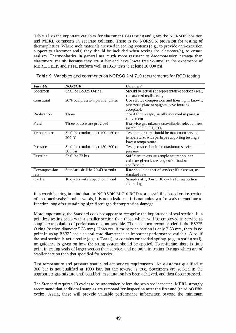
Table 9 lists the important variables for elastomer RGD testing and gives the NORSOK position and MERL comments in separate columns. There is no NORSOK provision for testing of thermoplastics. Where such materials are used in sealing systems (e.g., to provide anti-extrusion support to elastomer seals) they should be included when testing the elastomer(s), to ensure realism. Thermoplastics in general are much more resistant to decompression damage than elastomers, mainly because they are stiffer and have lower free volume. In the experience of MERL, PEEK and PTFE perform well in RGD tests to at least 10,000 psi.
Table 9 Variables and comments on NORSOK M-710 requirements for RGD testing
Variable NORSOK Comment Specimen Shall be BS325 O-ring Should be actual (or representative section) seal,
constrained realistically Constraint 20% compression, parallel plates Use service compression and housing, if known;
otherwise plate or spigot/sleeve housing acceptable
Replication Three 2 or 4 for O-rings, usually mounted in pairs, is convenient
Fluid Three options are provided If service gas mixture unavailable, select closest match; 90/10 CH4/CO2
Temperature Shall be conducted at 100, 150 or Test temperature should be maximum service 200 °C temperature, with perhaps supporting testing at
lowest temperature Pressure Shall be conducted at 150, 200 or Test pressure should be maximum service
300 bar pressure Duration Shall be 72 hrs Sufficient to ensure sample saturation; can
estimate given knowledge of diffusion coefficients
Decompression Standard shall be 20-40 bar/min Rate should be that of service; if unknown, use rate standard rate Cycles 10 cycles with inspection at end Samples at 1, 3 or 5, 10 cycles for inspection
and rating
It is worth bearing in mind that the NORSOK M-710 RGD test pass/fail is based on inspection of sectioned seals: in other words, it is not a leak test. It is not unknown for seals to continue to function long after sustaining significant gas decompression damage.
More importantly, the Standard does not appear to recognise the importance of seal section. It is pointless testing seals with a smaller section than those which will be employed in service as simple extrapolation of performance is not possible. The specimen recommended is the BS325 O-ring (section diameter 5.33 mm). However, if the service section is only 3.53 mm, there is no point in using BS325 seals as seal cord diameter is an important performance variable. Also, if the seal section is not circular (e.g., a T-seal), or contains embedded springs (e.g., a spring seal), no guidance is given on how the rating system should be applied. To re-iterate, there is little point in testing seals of larger section than service, and no point in testing O-rings which are of smaller section than that specified for service.
Test temperature and pressure should reflect service requirements. An elastomer qualified at 300 bar is not qualified at 1000 bar, but the reverse is true. Specimens are soaked in the appropriate gas mixture until equilibrium saturation has been achieved, and then decompressed.
The Standard requires 10 cycles to be undertaken before the seals are inspected. MERL strongly recommend that additional samples are removed for inspection after the first and (third or) fifth cycles. Again, these will provide valuable performance information beyond the minimum
49
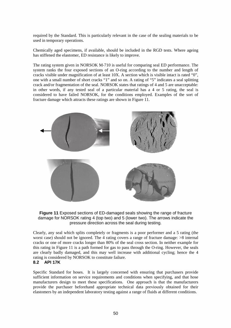
required by the Standard. This is particularly relevant in the case of the sealing materials to be used in temporary operations.
Chemically aged specimens, if available, should be included in the RGD tests. Where ageing has stiffened the elastomer, ED resistance is likely to improve.
The rating system given in NORSOK M-710 is useful for comparing seal ED performance. The system ranks the four exposed sections of an O-ring according to the number and length of cracks visible under magnification of at least 10X. A section which is visible intact is rated “0”, one with a small number of short cracks “1” and so on. A rating of “5” indicates a seal splitting crack and/or fragmentation of the seal. NORSOK states that ratings of 4 and 5 are unacceptable: in other words, if any tested seal of a particular material has a 4 or 5 rating, the seal is considered to have failed NORSOK, for the conditions employed. Examples of the sort of fracture damage which attracts these ratings are shown in Figure 11.
Figure 11 Exposed sections of ED-damaged seals showing the range of fracture damage for NORSOK rating 4 (top two) and 5 (lower two). The arrows indicate the
pressure direction across the seal during testing.
Clearly, any seal which splits completely or fragments is a poor performer and a 5 rating (the worst case) should not be ignored. The 4 rating covers a range of fracture damage: >8 internal cracks or one of more cracks longer than 80% of the seal cross section. In neither example for this rating in Figure 11 is a path formed for gas to pass through the O-ring. However, the seals are clearly badly damaged, and this may well increase with additional cycling; hence the 4 rating is considered by NORSOK to constitute failure. 8.2 API 17K
Specific Standard for hoses. It is largely concerned with ensuring that purchasers provide sufficient information on service requirements and conditions when specifying, and that hose manufacturers design to meet these specifications. One approach is that the manufacturers provide the purchaser beforehand appropriate technical data previously obtained for their elastomers by an independent laboratory testing against a range of fluids at different conditions.
50
8.3 NACE
Many Standards, for specific elastomer duties. As examples, ageing issues due to H2S exposures in sour liquid and gas environments are covered in NACE Standards TM0296-96 (Item no. 21227) and TM0187-98 (Item no. 21220) respectively. (These Standards are seen as supporting NACE Standard MR0175, which concerns “Sulfide stress cracking resistant metallic materials for oilfield equipment”.)
Other examples for elastomer usage are two explosive decompression NACE Standard tests TM0192 –98 (Item no. 21222) for moderate temperatures and TM0297-97 (Item no. 21229) for high temperatures; a considerable weakness with these two Standards is that CO2 is specified, ostensibly to accelerate testing times but in reality bringing about failure damage that might not occur at all in real service conditions as dissolved gas concentrations are unrealistically high with this gas (see section 4.4).
8.4 CORPORATE
Most, if not all, oil companies will have their own standard procedures associated with the use of elastomers; some organisations have many, other fewer. Their usage will be the basis for one-to-one contact with the supplier. In a few isolated cases, tests exist which have been developed by an oil company and published, and which potential suppliers use to indicate the good quality of their products; these tests may be undertaken by an independent laboratory. But a warning on this; in one such case, involving ED testing, it was found necessary to make the supplier aware that (i) a test developed and publicised by an oil company did not, in fact, form part of the official standard procedures for that oil company, and (ii) even if the product passed the test, this did not mean that the oil company would definitely use this product. Potential suppliers should ascertain from each end-user the exact requirements to be formally accepted as a supplier and to validate their goods.
51

52
9 BIBLIOGRAPHY FOR REVIEW Design “Seals and Sealing Handbook”, publ. DuPont de Nemours International S.A., Switzerland (1985). UKOOA Flexible Hose Management Guidelines document, issued by the UK Offshore Operators Association, No. 1 January 2003 (co-sponsored by the Institute of Petroleum, and the Health and Safety Executive). UKOOA Flexible Hose Management Guidelines document, issued by the UK Offshore Operators Association, No. 1 January 2003 (co-sponsored by the Institute of Petroleum, and the Health and Safety Executive). “Recommended Practice RP-F106: Factory Applied External Pipeline Coatings for Corrosion Control” - see: <http://exchange.dnv.com/BxWmWeb/TaskManager.asp?WCI=MenuArea&WCE=PMA_6_81 2!816!818&uid=ID20041021710580657197>
Guideline papers S Groves, “Project Guidelines for Selecting Seals for High Pressure Gas Duty and other Oilfield Service”, Proceedings “17th International Conference on Fluid Sealing”, York, UK, publ. BHR Group, Cranfield, Beds, UK, (8 – 10 April 2003). N Page and P Embury, “Elastomeric Seal Failure Analysis and Diagnosis”, Energy Rubber Group Educational Symposium, Galveston, Texas, USA (1998)
Others J Cowie, “Polymers: Chemistry and Physics of Modern Materials”, Blackie, Glasgow (1991).J Brydson, “Plastics Materials”, Butterworth-Heinemann, Oxford (1996).C Blow and C Hepburn (Eds), “Rubber Technology and Manufacture”, Butterworths, London(1985).F Eirich (Ed), “Science and Technology of Rubber”, Academic Press, New York (1978).D Morton-Jones, “Polymer Processing”, Chapman and Hall, London (1989).R Campion, “Permeation through Polymers for Processing Industry Applications”, MaterialsTechnology Institute of the Chemical Process Industries, St Louis, USA; distributed by ElsevierScience, Amsterdam, The Netherlands (2000).
53

APPENDIX 1 ELASTOMER COMPOUNDING ISSUES
Compounding is the process of formulating a recipe from the above ingredients such that, when all constituents are mixed and subsequently cured, the resulting elastomer has properties suitable for a specific (sealing) application. Achieving the correct balance is complex and relies very much the expertise of the seal manufacturer. The fine details may be commercially confidential but the user should understand the basic principles in order to carry out a meaningful technical dialogue with the manufacturer.
Many elastomers are compounded for general-purpose use, but particular duties may require more specific combinations of properties. For such situations, particular compounds can be formulated and their suitability established by appropriate tests. It is seldom sufficient to specify an elastomer by generic type alone.
The compounding ingredients are normally supplied to the seal manufacturer by specialist chemical companies. The seal manufacturer then mechanically mixes these additives with the base polymer and cures the resultant material to form a stable vulcanized elastomer. Most seals are made by curing the mix in a mould, which determines ultimate seal shape and dimensions. Due to varying amounts of shrinkage during this process the tolerances on moulded elastomeric parts are usually wider than for machined metal components. Individual classes of compound ingredient are discussed below.
A1.1 Base polymer
The base polymer (elastomer) comprises long chain molecules whose chemical nature determines the basic chemical and physical characteristics of the elastomer (see later). The choice of elastomer is mainly determined by fluid resistance, chemical resistance and thermal performance considerations. Usually, carbon atoms form the backbone of polymer molecules, with other atoms such as hydrogen or fluorine or larger chemical groupings (pendant groups) attached at regular intervals. The chemical nature of both the main chain and the side groups give rise to the affinity or otherwise of a polymer for other chemical species. The degree of affinity is roughly expressed thermodynamically in terms of polarity. For a better approach to determining the compatibility of polymers with fluids, the solubility parameter approach is very useful (see later).
A1.2 Cure system
The function of the cure system is to produce chemical crosslinks between neighbouring polymer chains. In relation to the length of the polymer chains there are only a few crosslinks, but these confer physical stability on the network. Curing is a chemical process and it generally takes place in a mould under the action of heat, required to break down the curatives to instigate the required reactions. Pressure is applied concurrently so that the correct product shape is achieved, and porosity within the elastomer (due to the volatilization of certain ingredients and cure by-products at early stages of cure) is avoided. Crosslinking agents include:
Organic peroxides - these usually introduce crosslinks directly between polymer backbones,Amines - these introduce crosslinks between polymer chains via an organic section with aminogroups either end (an “amine bridge”),Sulphur - commonly used in general purpose rubbers; the crosslink is formed from one or moresulphur atoms,Bisphenols - commonly used vulcanizing agents in FKM compounds; the crosslink is formedfrom a derivative of the bisphenol.
54
Elastomers for sealing applications should be fully cured (i.e., all of the crosslinking agent consumed), and have sufficient crosslink density to ensure material stability, particularly with respect to temperature. Use of inadequately cured material could have serious consequences as the curing reaction will continue in service resulting in massive compression set. The cure time and temperature are established by rheometric measurements. A rheometer monitors compound stiffness (torque) as curing proceeds at a particular temperature; from the resulting trace the optimum cure time can be determined. Good quality control procedures are essential to ensure consistent full cure of elastomer compounds.
NB. Different classes of curing systems should not be mixed; for instance, the presence of sulphur inhibits the curing activity of peroxides.
A1.3 Post-cure
The majority70 of seals based on FKM, FFKM and FEPM elastomers must be post-cured, that is, after removal from the mould articles are subjected to a secondary cure for a number of hours (typically 16 to 24) at atmospheric pressure and a temperature above the original cure temperature. Post-curing operations are invariably carried out in an oven. The process allows gaseous by-products to escape from the elastomer by diffusion, and aids consolidation of the crosslinked elastomer network. Other elastomers (e.g., NBR and HNBR) may, for some applications, also require a post-cure.
A1.4 Fillers
Fillers are particulate inorganic materials added to an elastomer primarily to modify itsproperties. They can change the
Tensile strength,Elastic modulus, or hardness,Tear strength,Abrasion resistance,Fluid-swell resistance,Chemical resistance,
of an elastomer compound. Filler materials include
Carbon black (by far the most common filler type – and of several different particle sizes,leading to different elastomer property levels),Calcium silicate,Treated calcium carbonate,Finely divided silica,Talc,Barytes,WhitingMagnesium carbonate.
Fillers are generally referred to as “reinforcing” or “non-reinforcing”. These terms are not welldefined but, generally, reinforcement of an elastomer refers to an increase in modulus and/orabrasion resistance. For most elastomers the addition of a reinforcing filler will increase itstensile strength, and indeed many elastomers can only reach practical levels of tensile strength
There are now some fluoroelastomers on the market which, according to their manufacturers, do not require a post-cure.
55
70
through the addition of such fillers. Carbon black and silica are the primary reinforcing fillers; larger particle size materials such as whiting do not reinforce. The ability of a filler to reinforce depends on its ability to bond to itself and to the elastomer - determined by such factors as size (surface area), shape, and the physical and chemical nature of the filler surface.
A1.5 Antidegradents
In static seal elastomers the function of antidegradents (or protective agents) is to inhibit
Oxidation,Ozone attack,Light (including uv) and thermal degradation,Flex-cracking (in dynamic applications).
Antidegradants are typically complex organic chemicals or waxes. As protection may berequired against more than one of the degradation sources listed, blends of chemicals are oftenused: this procedure lessens the chance of individual antidegredants exceeding their solubilitiesin the elastomer, and consequently migrating to the surface to cause an effect known as“bloom”. Selection of suitable antidegradents is complex because the effects which thechemicals may have on the vulcanization of the elastomer has to be taken into account.
A1.6 Plasticisers
Plasticizers include
Mineral oils, Waxes, Organic esters.
The function of a plasticiser in high quality components is to enhance the low temperature properties of the elastomer. By separating the molecular chains, plasticisers lower the glass transition temperature of the base polymer. However, this can come at the expense of high temperature ageing resistance. A secondary function of plasticiser is to ease mixing and moulding operations. Plasticisers may also be used as extenders to allow the incorporation of higher levels of filler. This is usually carried out to reduce costs, and may be difficult to detect, but it will lead to lower physical and chemical properties in almost any circumstances. Comparisons between apparently identical products require caution.
56
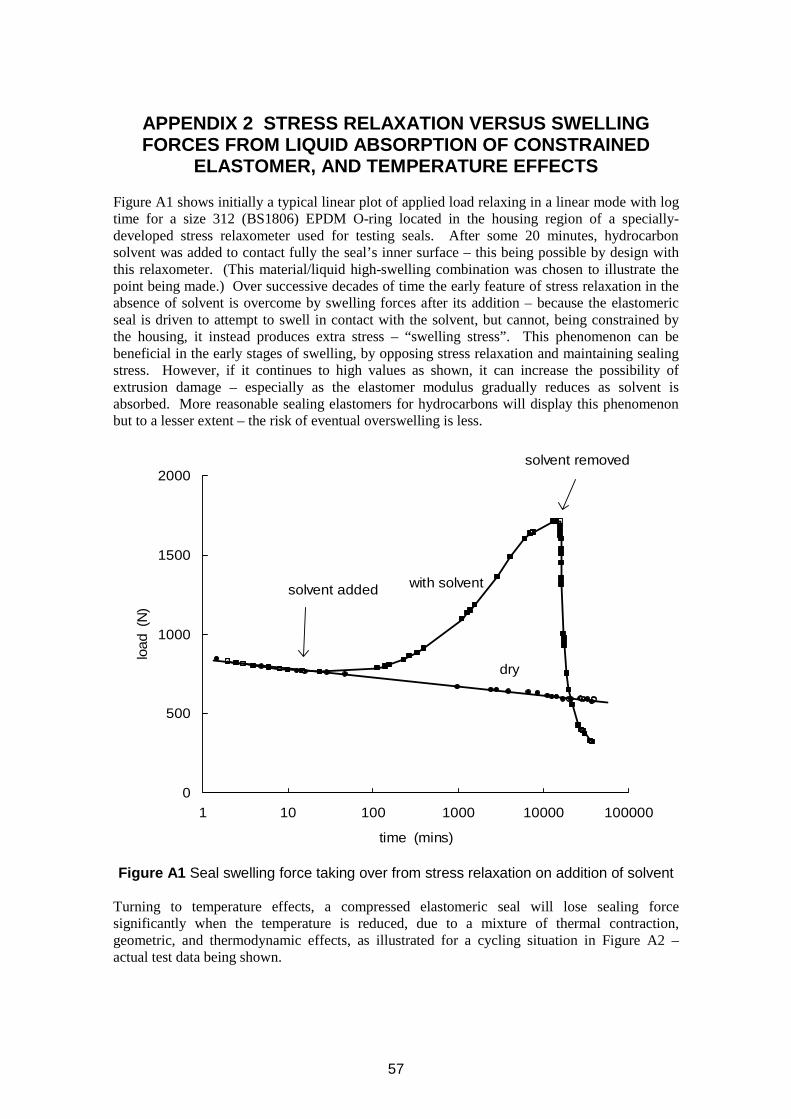
APPENDIX 2 STRESS RELAXATION VERSUS SWELLING lo
ad (
N)
FORCES FROM LIQUID ABSORPTION OF CONSTRAINED ELASTOMER, AND TEMPERATURE EFFECTS
Figure A1 shows initially a typical linear plot of applied load relaxing in a linear mode with log time for a size 312 (BS1806) EPDM O-ring located in the housing region of a specially-developed stress relaxometer used for testing seals. After some 20 minutes, hydrocarbon solvent was added to contact fully the seal’s inner surface – this being possible by design with this relaxometer. (This material/liquid high-swelling combination was chosen to illustrate the point being made.) Over successive decades of time the early feature of stress relaxation in the absence of solvent is overcome by swelling forces after its addition – because the elastomeric seal is driven to attempt to swell in contact with the solvent, but cannot, being constrained by the housing, it instead produces extra stress – “swelling stress”. This phenomenon can be beneficial in the early stages of swelling, by opposing stress relaxation and maintaining sealing stress. However, if it continues to high values as shown, it can increase the possibility of extrusion damage – especially as the elastomer modulus gradually reduces as solvent is absorbed. More reasonable sealing elastomers for hydrocarbons will display this phenomenon but to a lesser extent – the risk of eventual overswelling is less.
solvent removed 2000
1500
1000
500
0 1 10 100 1000 10000 100000
lso vent added with solvent
dry
time (mins)
Figure A1 Seal swelling force taking over from stress relaxation on addition of solvent
Turning to temperature effects, a compressed elastomeric seal will lose sealing force significantly when the temperature is reduced, due to a mixture of thermal contraction, geometric, and thermodynamic effects, as illustrated for a cycling situation in Figure A2 – actual test data being shown.
57
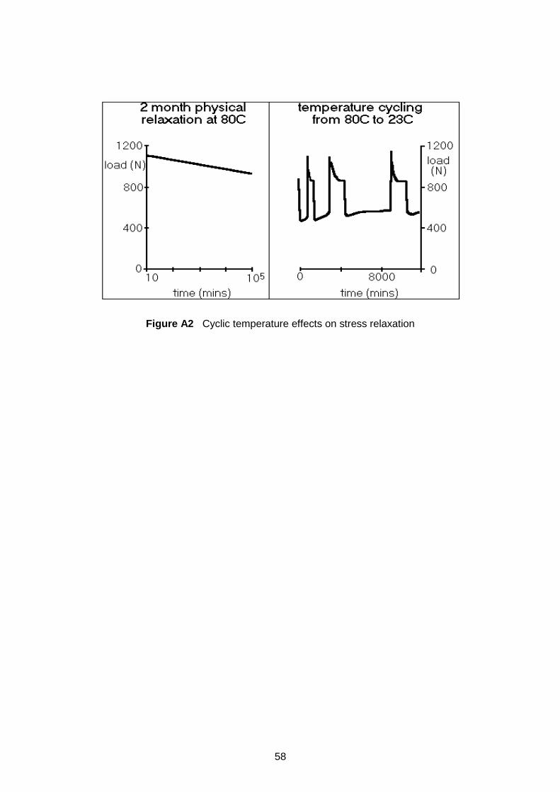
Figure A2 Cyclic temperature effects on stress relaxation
58
APPENDIX 3 HIGH PERFORMANCE THERMOPLASTIC DEVELOPMENT
The five major-use engineering thermoplastics comprise polyamide (PA), acetal (POM), polycarbonate (PC), modified PPO and polybutylene terephthalate (PBT). Acetal, for instance, can be used continuously in air at temperatures around 100 °C; if the material contacts fluids in service, the continuous use temperature will be lowered. Above this on the property scale are the (so called) super-engineering plastics (e.g., PEEK, PEK, PEKK, PPS, PES, PSU, PI, PAI, PAR, LCP, PEI, fluoroplastics). These are produced in lower volumes for specific demanding applications in the aerospace, automotive, electrical, chemical processing and offshore oil and gas industries. Of this group the fluoroplastics (particularly the perfluoroplastics71) possess the ultimate combination of heat stability and chemical resistance, and they are chosen for these qualities rather than mechanical performance per se: the latter has to be optimized as well as possible in the quest for utmost chemical resistance. Others such as PEEK have generally very good chemical and thermal resistance, combined with superb mechanical properties, which in themselves might be the reason for their choice. A good example would be the widespread use of PEEK as a back-up ring material, an application which demands exceptional strength and dimensional stability as well as good chemical and fluid resistance. Although a soft material compared to PEEK, PTFE is also widely specified for back-up rings, a role which can exploit its outstanding thermal and chemical resistance. PTFE is also used as a primary seal, but must be energised, usually via an embedded metallic spring or an elastomer. Polyurethanes are similar in a many of ways to polyamides but are little used as a thermoplastic moulding material due to their high cost. Polyurethane elastomers (and fibres), on the other hand, are very versatile and widely used [2], but not commonly in sealing applications. The development of polymers to replace metal as an engineering material has brought many benefits, the reduction in weight being especially important in the aerospace industry.
Two main strategies have evolved for the development of high performance engineering thermoplastics. The first seeks to stiffen the polymer chain, usually by the introduction of aromatic rings to the backbone. In this way, Tg is raised, as is Tm if the stiffer chains have a linear symmetrical structure and are sufficiently mobile to form ordered arrays with neighbouring macromolecules during processing. Taken to extremes, this approach results in materials which are extremely heat resistant but impossible to process by conventional means. In the case of the polyimides, this intractability has been overcome with the development and commercialisation of thermoplastic polyimides. These incorporate ether-containing units in the polymer backbone which greatly improves its flexibility, but at the expense of some thermal stability.
The other general approach to raising performance, particularly chemical and thermal resistance, has entailed the “replacement” of the (relatively) weak C-H bonds in the polymer structure with significantly stronger C-F links. The best known perfluoroplastic is undoubtedly poly(tetrafluoroethylene)72, the fluorinated analogue of PE. With PTFE however, high thermal stability arises from the combination of (1) high crystallinity and (2) the absence of C-H bonds; a jacket of fluorine atoms surrounds the all-carbon backbone. The high crystallinity is a direct result of the linear chain growth (no branching) during synthesis. While this is desirable for chain packing, it is also responsible for the poor cold flow of PTFE, which in turn explains the extremely high MW necessary for commercial PTFE: in general, chains must be sufficiently branched or long to entangle and ensure reasonable mechanical properties so that, for PTFE, very long macromolecules are necessary. However, high MW means high melt viscosity, hence
71 Polymers in which all C-H bonds which can be “replaced” are fluorinated. 72 More commonly known as Teflon (DuPont tradename), Teflon PTFE, or just PTFE.
59
the impossibility of processing PTFE by conventional means: special techniques such as compression moulding, paste extrusion and ram extrusion are required. In all three methods, PTFE particles are sintered, that is, fused above Tm (an inter-surface phenomenon). In compression moulding PTFE powder is compacted in a mould at room temperature into a preform prior to a sintering, usually in an air-circulating oven. In ram extrusion the die is continuously charged with free-flowing PTFE powder, which is compressed and forced into the sintering zone of the extruder. Paste extrusion requires the addition of a processing aid, allowing a cylindrical preform to be fabricated. This is then forced through a heated die where, within the sintering region, the extrusion aid is vaporised and the PTFE fused; the lubricant is completely removed during the process. In all PTFE processing methods, incomplete fusion leaves microvoids in the polymer bulk and these can affect properties73, particularly permeation behaviour. This is used to advantage for some filtering applications. This feature has been highlighted as a possible starting point for explosive (rapid gas) decompression failure of PTFE.
It was in order to overcome the difficulties of processing PTFE that many years ago impetus was given to the development of numerous TFE-based co- and terpolymers; commoner choices include HFP, PPVE, PMVE, VDF and E. The major commercial polymers resulting from these developments are ECTFE, ETFE, FEP, PFA and MFA. The copolymers have improved mechanical properties since the asymmetric commoner allows increased chain entanglement, which reduces slippage under loading. An important consequence of copolymerization is the reduction in MW it allows, enabling the modified polymers to be melt processed using conventional equipment. Polymers synthesized from partially fluorinated monomers (PVDF, PVF, PCTFE) are more easily processed than PTFE, but none has its superior thermal and chemical resistance.
Some high performance polymers are completely amorphous but have a high Tg, so that they function below this temperature; examples include PES, PPSU, PSU and PAI. By and large these materials are functional as long as the service temperature remains below Tg but mechanical properties degenerate rapidly at this transition. Because they are glasses, with more free volume than semi-crystalline thermoplastics, the amorphous engineering plastics tend to have a lower resistance to chemical attack and dissolution. In some applications their optical clarity is a desirable attribute, but this varies according to polymer type; for example, Teflon AF is colourless, Ultem PEI is amber brown.
73 The incorporation of small (<1 mole%) amounts of a second fluorinated monomer during TFE polymerization, to produce “modified PTFE”, has resulted in some marked property improvements.
60
APPENDIX 4 DETAILS OF ARRHENIUS APPROACH, & OTHERFACTORS
It has become an established practice over recent years to apply the Arrhenius equation, derived from physical chemistry, to property changes. The equation has been applied to two general areas:
(a) Chemical ageing effects on a mechanical property, where k = A exp (-Ea/RT) (b) Permeation, diffusion, solubility, where e.g. D = D0 exp (-Ea/RT)
where k is reaction rate, D is diffusion coefficient, A and D0 are frequency-associated constants, T is absolute temperature, R is the gas constant, and Ea for each is the activation energy of that process. In standard physical chemistry, k is measured by considering concentration changes, wheras for the diffusion-related properties, the coefficients represent rate per unit cube. From these equations, for both chemical and diffusion-related situations, the plotting of log k or log D against 1/T (°Kelvin) should give straight lines, of slope – Ea/R. This has been shown to apply for numerous situations.
The –Ea/RT term is a statistically-derived term, associated with • the amount of reaction occurring (numbers of molecules attaining an energy level greater
than Ea) for (a) • the probability governing the number of big enough holes (between the rubber molecular
chain segments as they continually move kinetically) capable of accepting diffusing molecules of another species for (b).
Solubility also follows a similar equation (using the solubility coefficient s). As permeation involves both diffusion and solubility (see section 4.3.1), its temperature dependence also follows an analogous Arrhenius equation.
A convenient way of doing this is by defining rate as being reciprocal time, the time in question being the duration of ageing to a specified stiffness (etc) loss or gain. This is repeated after exposures at other temperatures, and Arrhenius plots developed. Figure A3 shows a schematic of three typical tensile-modulus versus time plots that have been observed as an elastomer is aged in a hostile fluid at three high temperatures (well above service temperature for the application in mind). In reality, each plot had several individual points on it, each being the average of three measurements. An initial physical softening due to fluid absorption was followed by two chemical stages – crosslinking, then degradation. Taking the reciprocal of the time to each maximum value as a rate associated with good performance for each temperature, the Arrhenius plot shown in Figure A4 is obtained. An extrapolation to service temperature could then be carried out. (Alternatively, rates k can be quantified by the local gradient applying for any stage.)
61
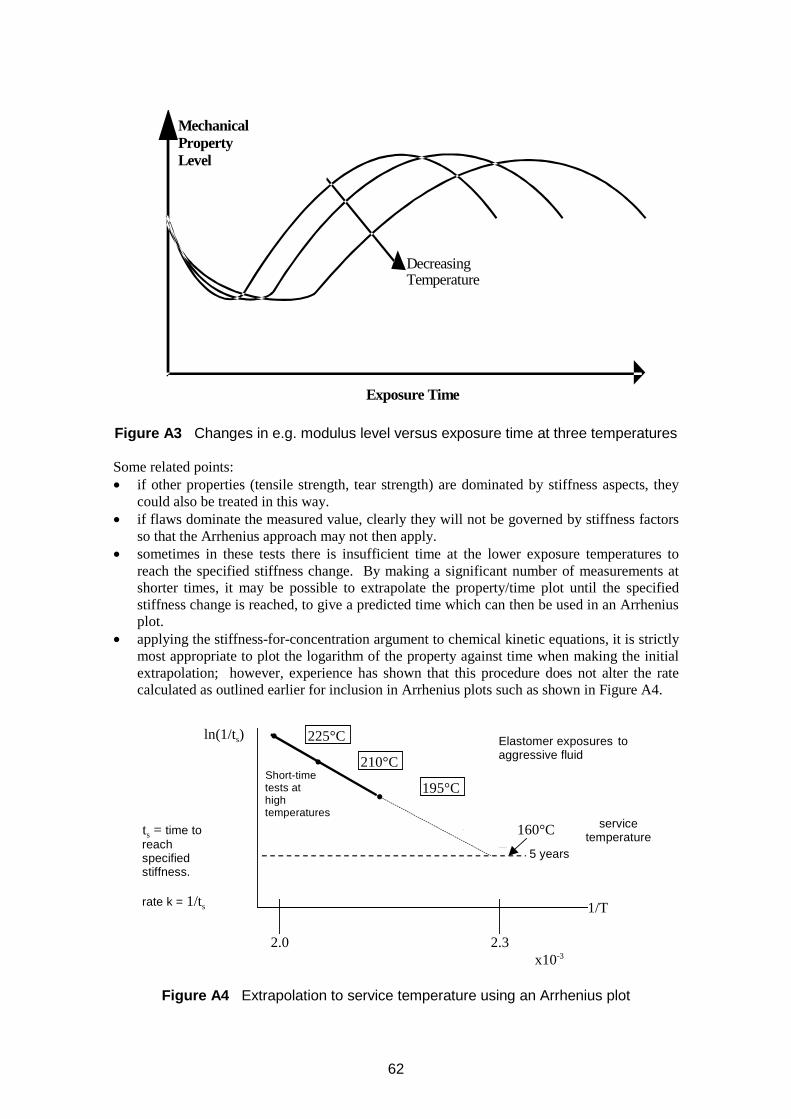
Decreasing Temperature
Mechanical Property Level
Exposure Time
Figure A3 Changes in e.g. modulus level versus exposure time at three temperatures
Some related points: • if other properties (tensile strength, tear strength) are dominated by stiffness aspects, they
could also be treated in this way. • if flaws dominate the measured value, clearly they will not be governed by stiffness factors
so that the Arrhenius approach may not then apply. • sometimes in these tests there is insufficient time at the lower exposure temperatures to
reach the specified stiffness change. By making a significant number of measurements at shorter times, it may be possible to extrapolate the property/time plot until the specified stiffness change is reached, to give a predicted time which can then be used in an Arrhenius plot.
• applying the stiffness-for-concentration argument to chemical kinetic equations, it is strictly most appropriate to plot the logarithm of the property against time when making the initial extrapolation; however, experience has shown that this procedure does not alter the rate calculated as outlined earlier for inclusion in Arrhenius plots such as shown in Figure A4.
ln(1/ts)
ts = time to reach specified stiffness.
rate k = 1/ts
•
•
•
ime
225°C
210°C
195°C Short-t
tests at high temperatures
Elastomer exposures to aggressive fluid
160°C service temperature
5 years
1/T
2.0 2.3 x10⁻³
Figure A4 Extrapolation to service temperature using an Arrhenius plot
62
A fair criticism of the example just discussed is that a three-point Arrhenius plot gives a poor statistical basis for a subsequent extrapolation. This is undeniable; however, this example was deliberately chosen to illustrate the paucity of data that are sometimes available to engineers when making predictions of this type. These tests were for an oilfield application, where the seals were to be made from a chemically resistant elastomer. The ageing exposures were conducted for several months at temperatures between 200°C and 300°C, and at fluid pressures of 15,000psi (ca. 100MPa); hence the ageing durations were long, and experimentation was difficult. Moreover, the oilfield engineers required the data as soon as possible for offshore operational reasons, as they had a “window” of opportunity for putting the appropriate equipment in place. In these conditions, the data shown represented a prediction for the engineers to employ, adding their own safety factor as thought necessary. One approach to help this is to use a statistical assessment of the data plotted, and hence derive the “worst case” extrapolation.
Another extrapolation possibility exists for some cases where circumstances decree that only a few aged property magnitudes can be obtained. If the chemical mechanism of the appropriate ageing-induced deterioration is known and can be followed in a relatively-easy way by a suitable chemical analytical technique, giving many data, a reliable activation energy so-derived could be applied to the few property data obtained, to give confidence to any extrapolation to service temperature.
A4.1 Permeation/diffusion etc at high pressures
Arrhenius-type plots of permeation, diffusion and solubility can be in the form of series of bands rather then a line, as both time and high pressure can cause values to decrease (by allowing physical compaction of the polymer to occur. This has been verified for elastomers and thermoplastics at high gas pressures.
A4.1.2 Factors which can override predictions.
Attempts to predict when failure will occur due to other factors such as swelling require extra stages, i.e. (loss of) stiffness might be used to quantify the swelling meaningfully by an Arrhenius approach, but less predictable factors such as extrusion might also intervene. Validation testing is required in such a case. Predicting the onset of explosive decompression damage can be equally difficult - the usual approach is to design housings, etc, that experience has shown will limit damage (and maintain sealing, etc) to the greatest extent, and perform multicycle tests at higher pressures and temperatures than service ones to determine the best materials. In a similar way, crack growth fatigue issues may be changed during ageing and these may override other factors.
63

Printed and published by the Health and Safety ExecutiveC30 1/98
Printed and published by the Health and Safety ExecutiveC0.06 02/05

9 78071 7 629695
ISBN 0-7176-2969-4
RR 320
£15.00

Ela
stom
ers fo
r fluid
conta
inm
ent in
offsh
ore
oil a
nd
gas p
rod
uctio
n: G
uid
elin
es a
nd
revie
w
HS
E BO
OK
S