Embed Size (px)
Citation preview

RESEARCH PROJECT AT
UNIVERSITY OF NEVADA, RENO
QUARTERLY REPORT
Jan. 1, 2016 to March 31, 2016 Period
Year 1 Project
Development and Seismic Evaluation of Pier Systems w/ Pocket Connections
and Square PT/UHPC Columns
Submitted by
M. Saiidi, A. Itani, and A. Mohebbi
Department of Civil and Environmental Engineering
University of Nevada, Reno
Reno, Nevada
Submitted
April 2016
2
TABLE OF CONTENTS
A. Description of Research Project ................................................................................................. 3
A.1 Problem Statement ................................................................................................................... 3
A.2 Contribution to Expanding Use of ABC in Practice ................................................................ 4
A.3 Research Approach and Methods ............................................................................................ 4
A.4 Description of Tasks to Be Completed in Research Project .................................................... 6
Task 1- Literature Review, 100% Completed ............................................................................. 6
Task 2- Preliminary Design of a Single Column Model, 100% completed................................ 7
Task 3- Conduct Nonlinear Finite Element Analysis of Test Models ...................................... 13
Model for Single Column Bent, 100% Completed ..................................................... 13
Model for Two Column Bent, 66% Completed ..................................................... 16
Task 4- Construct the Test Models, Conduct Shake Table ....................................................... 18
Single Column Bent............................................................................................................... 18
Construction, Tests, and Process Test Data, 100% Completed ........................................ 18
Lesson learned .................................................................................................................. 26
Two Column Bent ................................................................................................................. 26
Construction, Tests, and Process Test Data, 33% Completed .......................................... 26
Task 5 – Conduct analytical studies of the column and pier models, Pending ......................... 31
Task 6 – Develop design method and numerical examples, Pending ....................................... 31
Task 7 – Summarize the investigation and the results in a draft final report, Pending ............ 31
A.5 Expected Results and Specific Deliverables .......................................................................... 31

3
Year 1 Project: Development and Seismic Evaluation of Pier Systems w/ Pocket Connections and Square PT/UHPC Columns
UNR Project Website: http://wolfweb.unr.edu/homepage/saiidi/USDOT/index.html
ABC-UTC Project Website: http://abc-utc.fiu.edu/index.php/research/project/development-and-seismic-
evaluation-of-pier-systems-with-pocket-connections
A. Description of Research Project
A.1 Problem Statement
Accelerated bridge construction relies heavily on prefabricated reinforced concrete members.
Connections of prefabricated members are particularly critical in moderate and high seismic
zones because earthquake forces place high demand on nonlinear deformation capacity of
adjoining members. Structural integrity of the bridge has to be maintained by capacity-protected
connections that experience no or little damage.
Various connections have been explored in the past few years. These connections may be placed
in two categories of coupler and pocket connections. Promising results have been obtained for
different versions of both categories, although much research and development have to be done
before reliable and proven design methods of the type used in practice can be recommended.
With a few exceptions, past research on seismic response of ABC connections has focused on
conventional reinforcing steel and concrete materials. The PI has pointed out that ABC provides
an opportunity to improve the seismic beyond the target performance objectives of current codes,
and this view has been well received by leading bridge earthquake engineers. Standard cast-in-
place (CIP) bridges are designed to undergo large inelastic deformations to dissipate the
earthquake energy, but must not collapse. It is understood that these bridges would need to be
decommissioned for major repair or replacement following the earthquake, at a time they are

4
needed the most for a functioning lifelines for emergency response vehicles. A new paradigm is
being promoted and being embraced by leading bridge engineers to utilize advanced materials.
Research has been conducted to demonstrate the feasibility and merit of advanced materials for
CIP construction. Through a FHWA Innovative Bridge Research and Deployment (IBRD)
projects, some of these advanced materials are being implemented in an actual
bridge. Specifically, advanced materials and methods are intended to minimize damage to
plastic hinges and permanent drift of the bridge. The objective of the proposed project is to
develop and evaluate earthquake-resistant yet resilient bridge piers that incorporate prefabricated
elements for use in ABC in moderate and high seismic zones.
A.2 Contribution to Expanding Use of ABC in Practice
Despite numerous advantages of ABC, states in moderate and high seismic zones have not been
able embrace ABC because of insufficient research results and guidelines for seismic design of
prefabricated members and connections. Upon successful development and evaluation of the
proposed bents, issues will be identified and addressed and preliminary design guidelines will be
developed along with illustrative design examples to facilitate the adoption of the proposed
designs and expand the use of ABC in practice. The potential improvements that the use of
advanced materials will provide over conventional reinforced concrete could also serve as further
incentive to states that might be hesitant in adopting ABC.
A.3 Research Approach and Methods
The overall objective of the proposed study is to develop and evaluate resilient bridge piers
consisting of prefabricated columns and cap beams subjected to simulated earthquake loading on
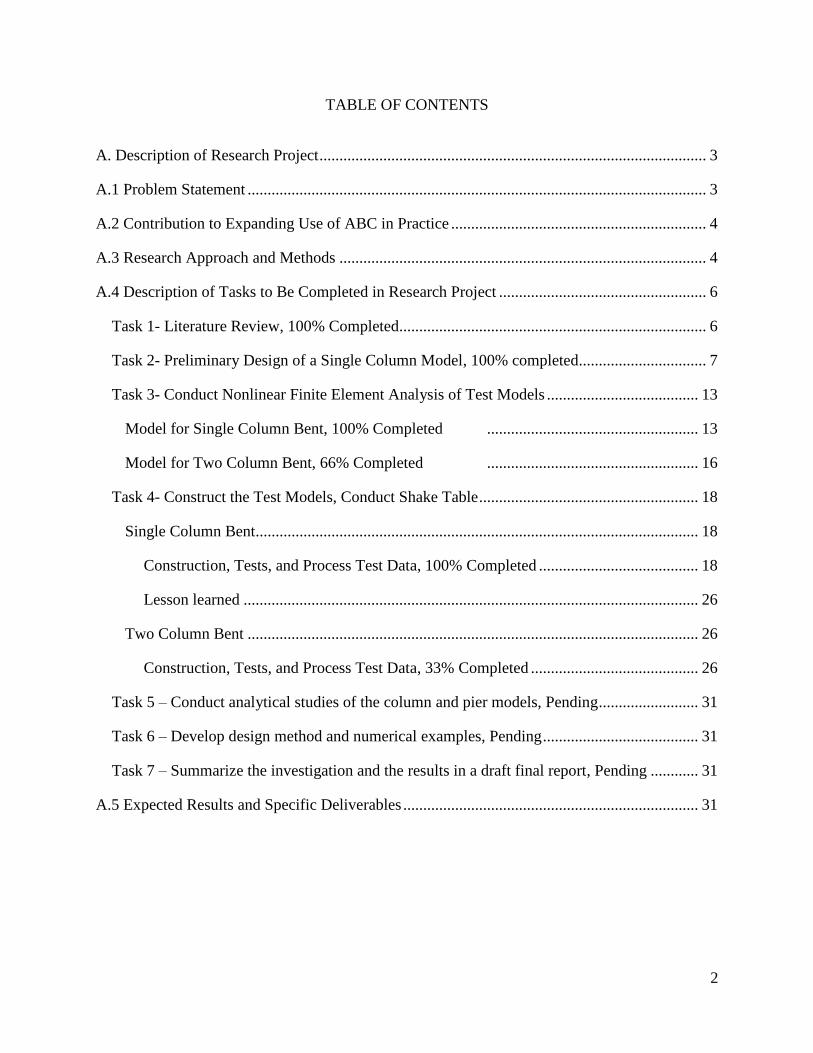
shake tables. The study will focus on precast columns that are post-tensioned with unbonded
5
carbon fiber reinforced polymer (CFRP) tendons and are connected to the footings and the cap
beam using pocket connections. Specific objectives of the project are to determine:
a) the seismic performance of pocket connections with unbonded post-tensioned columns,
b) the seismic performance of square precast PT columns,
c) the effectiveness of CFRP tendons in minimizing residual displacements under strong
earthquakes,
d) the performance of two different ultra-high performance concrete (UHPC) used in plastic
hinges of solid and hollow columns, and
e) design considerations and methods for connections, CFRP PT columns, precast square
columns, and plastic hinges with UHPC.
Pocket connections will be incorporated in the piers because this category of ABC connections
has shown promising results while it does not violate the current AASHTO and Caltrans seismic
codes because no mechanical couplers are utilized in pocket connections. Unbonded PT
columns will be studied because it is known that unbonded PT reduces permanent drifts under
seismic loads. CFRP tendons rather than steel will be utilized because based on extensive
interaction of the PI with bridge designers, he is aware of reluctance of engineers in using
unbonded tendons in concrete structures due to concerns for corrosion and the fact that CFRP is
resistant to corrosion. Hollow columns will be included in the study, because they are lighter
and can expedite construction. The study of different UHPC materials is intended to assess and
compare the resilience of plastic hinges using some of the most promising materials.
Development of design methods is intended to provide designers of piers for use in ABC. It is
envisioned that approximately one-third scale columns and pier models will be designed,
constructed, and tested on a shake table.

6
A.4 Description of Tasks to Be Completed in Research Project
The study consists of the following tasks. The tasks are described and the status of each are
presented in this section.
Task 1- Literature Review 100% Completed
Accelerated bridge construction (ABC) has recently become popular due to its numerous
advantages such as minimizing traffic delays and road closures, as well as reducing the
construction time and efforts. ABC relies heavily on prefabricated reinforced concrete members.
Connections of prefabricated members are particularly critical in moderate and high seismic
zones because earthquake forces place high demand on nonlinear deformation capacity of
adjoining members. Structural integrity of the bridge has to be maintained by capacity-protected
connections that experience no or little damage. Various connections have been explored in the
past few years. These connections can be placed in two categories of coupler and pocket
connections. Promising results have been obtained for different versions of both categories,
although much research and development have to be done before reliable and proven design
methods of the type used in practice can be recommended.
One of the methods to connect prefabricated bridge columns to footings is pocket connections.
This research project concentrates on these types of connections as they have shown promising
results while not violating the current AASHTO and Caltrans seismic codes. Innovation
concepts of this research project are as follows:
• Precast column and footing with pocket connection
• Post-tensioning using unbonded Carbon Fiber Reinforced Polymer (CFRP) tendons
• Ultra-High Performance Concrete (UHPC) in plastic hinge zone
7
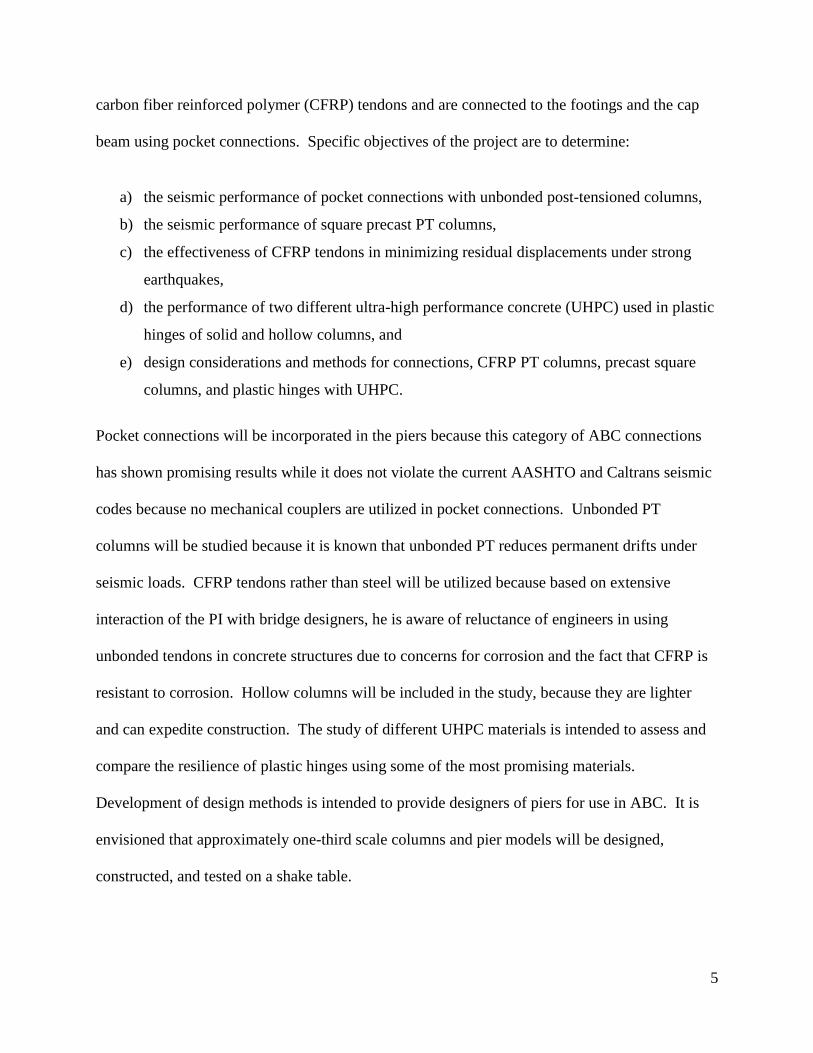
This study focuses on a precast square column that is post-tensioned with unbonded carbon
fiber reinforced polymer (CFRP) tendons and is connected to the footing using pocket
connection. Specific objectives of the project are to determine:
a) the seismic performance of pocket connection with unbonded post-tensioned column,
b) the appropriate embedment length of square precast columns in pocket connections
c) the effectiveness of CFRP tendons in minimizing residual displacements under strong
earthquakes,
d) the optimized level of PT force based on column geometric and strength characteristics
e) the performance of ultra-high performance concrete (UHPC) used in plastic hinge zone of
the square column, and
f) design considerations and methods for connections, CFRP PT columns, precast columns,
and plastic hinges with UHPC.
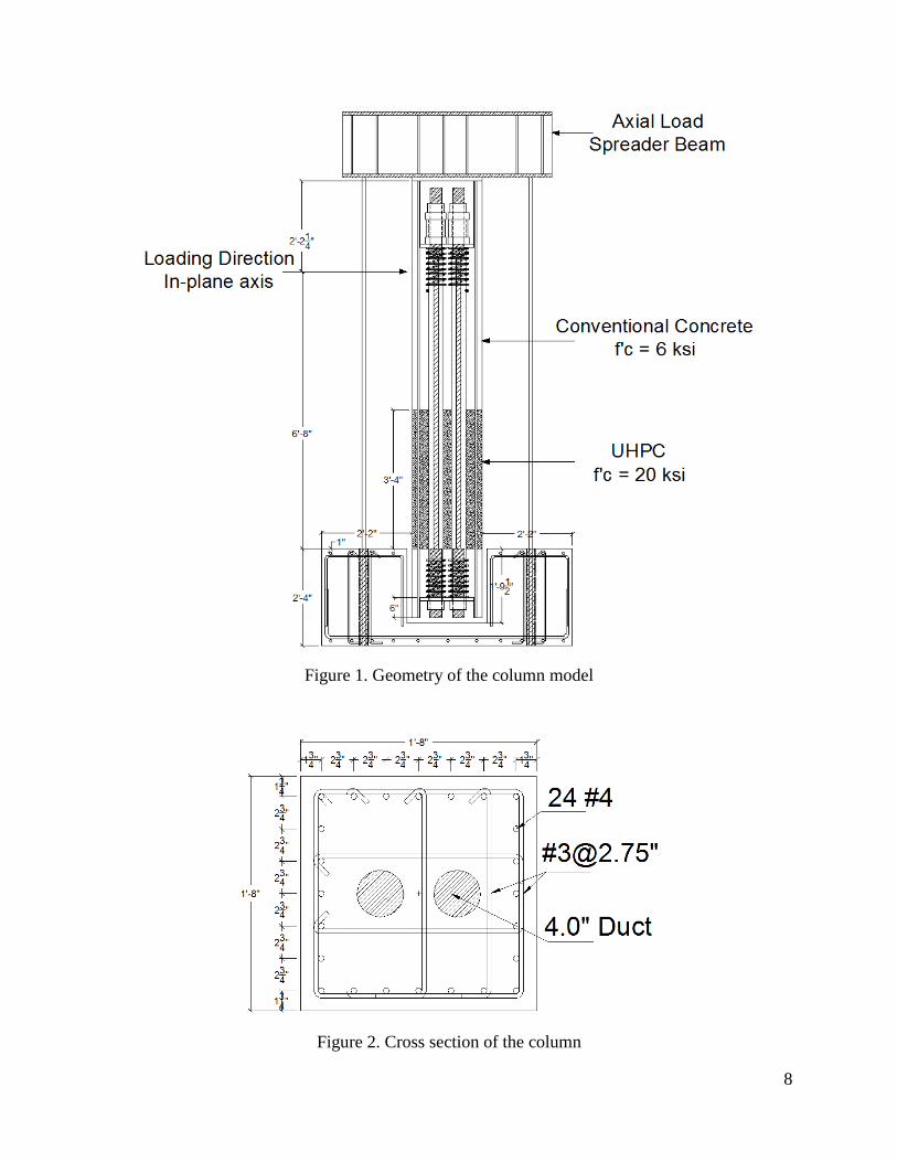
Task 2- Preliminary Design of a Single Column Model 100% completed
To accomplish the objectives of the study, a 1/3 scale of a square bridge column was designed
according to AASHTO Guide Specifications for LRFD Seismic Bridge Design for a location in
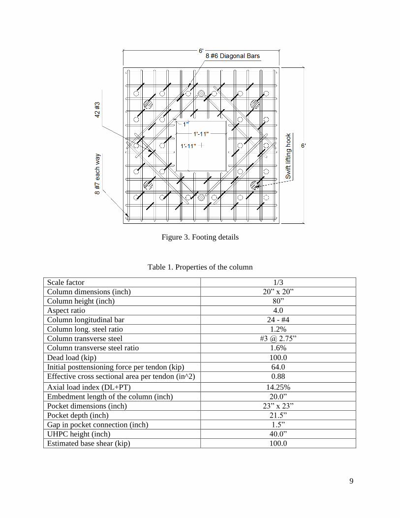
down town Los Angeles, CA. Figures 1-3 show the geometry and cross section of the column as
well as footing details. The properties of the bridge column is given in Table 1.
8
Figure 1. Geometry of the column model
Figure 2. Cross section of the column
9
Figure 3. Footing details
Table 1. Properties of the column
Scale factor 1/3
Column dimensions (inch) 20” x 20”
Column height (inch) 80”
Aspect ratio 4.0
Column longitudinal bar 24 - #4
Column long. steel ratio 1.2%
Column transverse steel #3 @ 2.75”
Column transverse steel ratio 1.6%
Dead load (kip) 100.0
Initial posttensioning force per tendon (kip) 64.0
Effective cross sectional area per tendon (in^2) 0.88
Axial load index (DL+PT) 14.25%
Embedment length of the column (inch) 20.0”
Pocket dimensions (inch) 23” x 23”
Pocket depth (inch) 21.5”
Gap in pocket connection (inch) 1.5”
UHPC height (inch) 40.0”
Estimated base shear (kip) 100.0

10
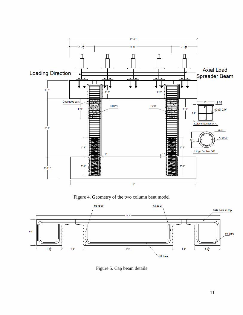
A 1/3 scale of two column bent was designed according to AASHTO Guide Specifications for
LRFD Seismic Bridge Design. The geometry of the bent is shown in Fig. 4. The columns had
moment connection at the top and pin connection at the bottom. Using ABC pocket connection,
the precast columns were inserted into the precast footing and extended in the precast cap beam.
The embedment length of the columns for the pocket connections was 1.0 times the column
dimension at the top and 1.35 times the column dimension at the bottom. UHPC and ECC were
used in the plastic hinges to minimize seismic damage. The height of UHPC and ECC was 1.5
times the column dimension. Figures 5-8 show cap beam and footing details. The properties of
the two-column bent are summarized in Table 2.
Table 2. Properties of the two column bent
Scale factor 1/3
Bent cap dimensions (inch) 19” x 26”x 134”
Footing dimensions (inch) 23” x 36” x 132”
Column dimensions (inch) 14” x 14”
Column clear height (inch) 61.0”
Aspect ratio 4.35
Column long. bar 8 - #5
Column long. steel ratio 1.26%
Column transverse steel #3 @ 2.0”
Column transverse steel ratio 2%
Long. bar at hinge section 6 #5
Long. steel ratio at hinge section 2.36%
Transverse steel at hinge section #3 @ 1.5”
Axial load index 6.4%
Embedment length of the column at the top (inch) 14.0”
Embedment length of the column at the bottom (inch) 19.0”
Gap in pocket connection (inch) 1.0”
Dead load (kip) 100.0
Mp.Hinge / Mp.Col 40%
Base shear (kip) 72
Shear demand (left col., right col.) (kip) 29 , 43
Column shear capacity (left col., right col.) (kip) 74 , 74
Hinge shear capacity (left col., right col.) (kip) 47 , 79
11
Figure 4. Geometry of the two column bent model
Figure 5. Cap beam details

12
Figure 6. Cap beam cross section
Figure 7. Footing details
Figure 8. Footing section A-A
13
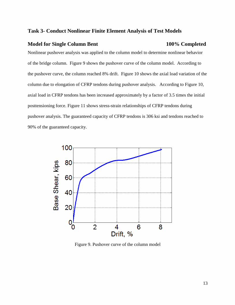
Task 3- Conduct Nonlinear Finite Element Analysis of Test Models
Model for Single Column Bent 100% Completed
Nonlinear pushover analysis was applied to the column model to determine nonlinear behavior
of the bridge column. Figure 9 shows the pushover curve of the column model. According to
the pushover curve, the column reached 8% drift. Figure 10 shows the axial load variation of the
column due to elongation of CFRP tendons during pushover analysis. According to Figure 10,
axial load in CFRP tendons has been increased approximately by a factor of 3.5 times the initial
posttensioning force. Figure 11 shows stress-strain relationships of CFRP tendons during
pushover analysis. The guaranteed capacity of CFRP tendons is 306 ksi and tendons reached to
90% of the guaranteed capacity.
Figure 9. Pushover curve of the column model

14
Figure 10. Axial load variation of the column and CFRP tendons
Figure 11. Stress-strain relationship of CFRP tendons
15
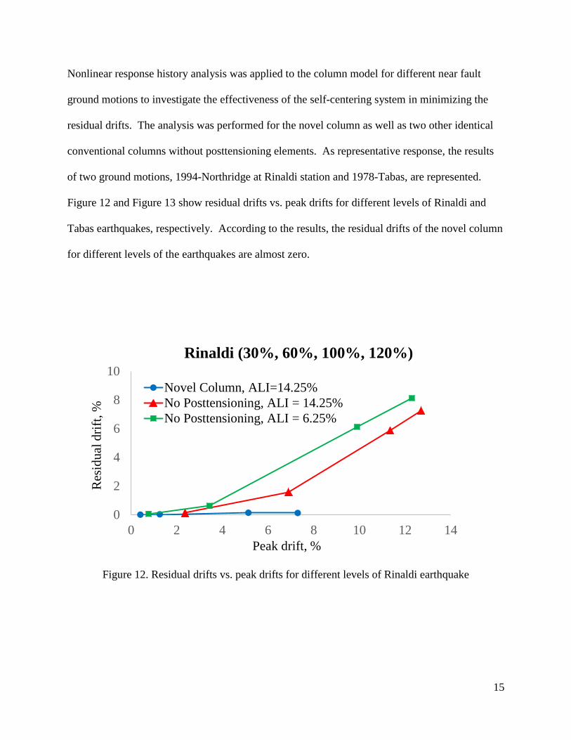
Nonlinear response history analysis was applied to the column model for different near fault
ground motions to investigate the effectiveness of the self-centering system in minimizing the
residual drifts. The analysis was performed for the novel column as well as two other identical
conventional columns without posttensioning elements. As representative response, the results
of two ground motions, 1994-Northridge at Rinaldi station and 1978-Tabas, are represented.
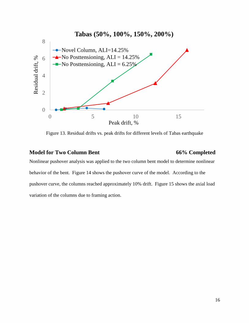
Figure 12 and Figure 13 show residual drifts vs. peak drifts for different levels of Rinaldi and
Tabas earthquakes, respectively. According to the results, the residual drifts of the novel column
for different levels of the earthquakes are almost zero.
Figure 12. Residual drifts vs. peak drifts for different levels of Rinaldi earthquake
0
2
4
6
8
10
0 2 4 6 8 10 12 14
Res
idu
al d
rift
, %
Peak drift, %
Rinaldi (30%, 60%, 100%, 120%)
Novel Column, ALI=14.25%
No Posttensioning, ALI = 14.25%
No Posttensioning, ALI = 6.25%
16
Figure 13. Residual drifts vs. peak drifts for different levels of Tabas earthquake
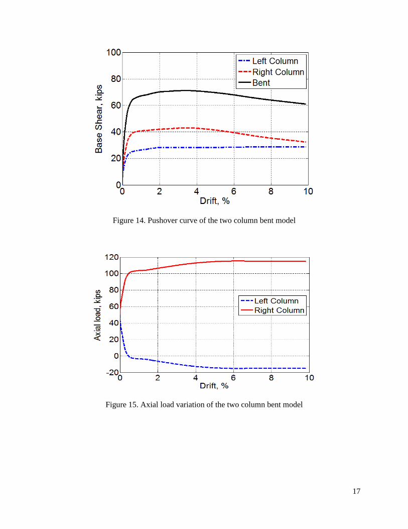
Model for Two Column Bent 66% Completed
Nonlinear pushover analysis was applied to the two column bent model to determine nonlinear
behavior of the bent. Figure 14 shows the pushover curve of the model. According to the
pushover curve, the columns reached approximately 10% drift. Figure 15 shows the axial load
variation of the columns due to framing action.
0
2
4
6
8
0 5 10 15
Res
idu
al d
rift
, %
Peak drift, %
Tabas (50%, 100%, 150%, 200%)
Novel Column, ALI=14.25%
No Posttensioning, ALI = 14.25%
No Posttensioning, ALI = 6.25%
17
Figure 14. Pushover curve of the two column bent model
Figure 15. Axial load variation of the two column bent model
18
Task 4- Construct the Test Models, Conduct Shake Table
Single Column Bent
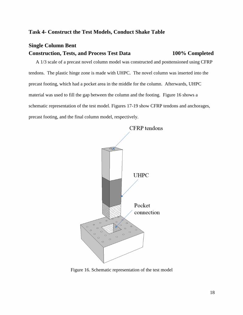
Construction, Tests, and Process Test Data 100% Completed
A 1/3 scale of a precast novel column model was constructed and posttensioned using CFRP
tendons. The plastic hinge zone is made with UHPC. The novel column was inserted into the
precast footing, which had a pocket area in the middle for the column. Afterwards, UHPC
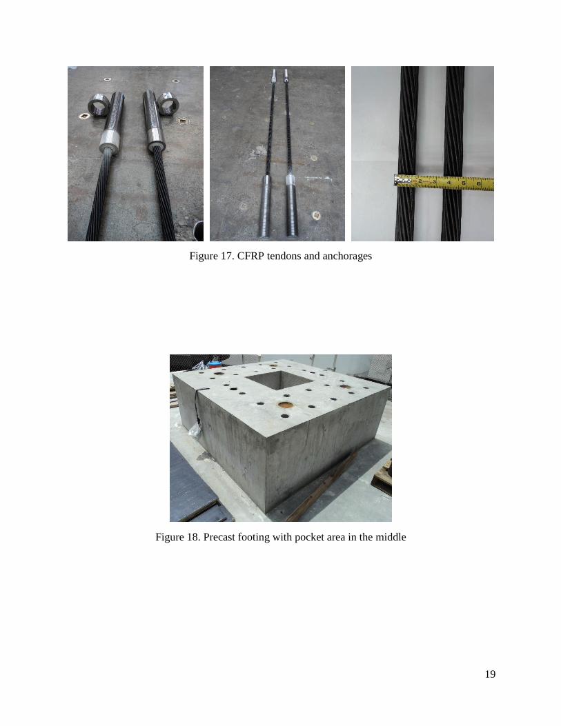
material was used to fill the gap between the column and the footing. Figure 16 shows a
schematic representation of the test model. Figures 17-19 show CFRP tendons and anchorages,
precast footing, and the final column model, respectively.
Figure 16. Schematic representation of the test model
19
Figure 17. CFRP tendons and anchorages
Figure 18. Precast footing with pocket area in the middle
20
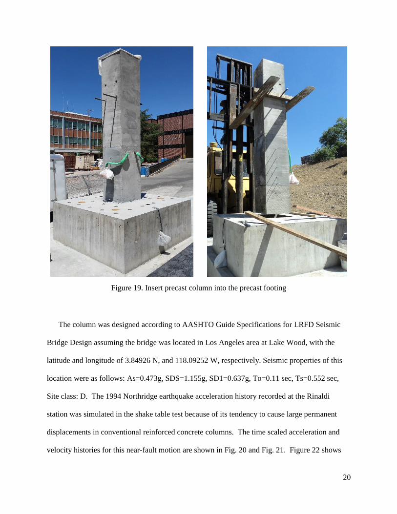
Figure 19. Insert precast column into the precast footing
The column was designed according to AASHTO Guide Specifications for LRFD Seismic
Bridge Design assuming the bridge was located in Los Angeles area at Lake Wood, with the
latitude and longitude of 3.84926 N, and 118.09252 W, respectively. Seismic properties of this
location were as follows: As=0.473g, SDS=1.155g, SD1=0.637g, To=0.11 sec, Ts=0.552 sec,
Site class: D. The 1994 Northridge earthquake acceleration history recorded at the Rinaldi
station was simulated in the shake table test because of its tendency to cause large permanent
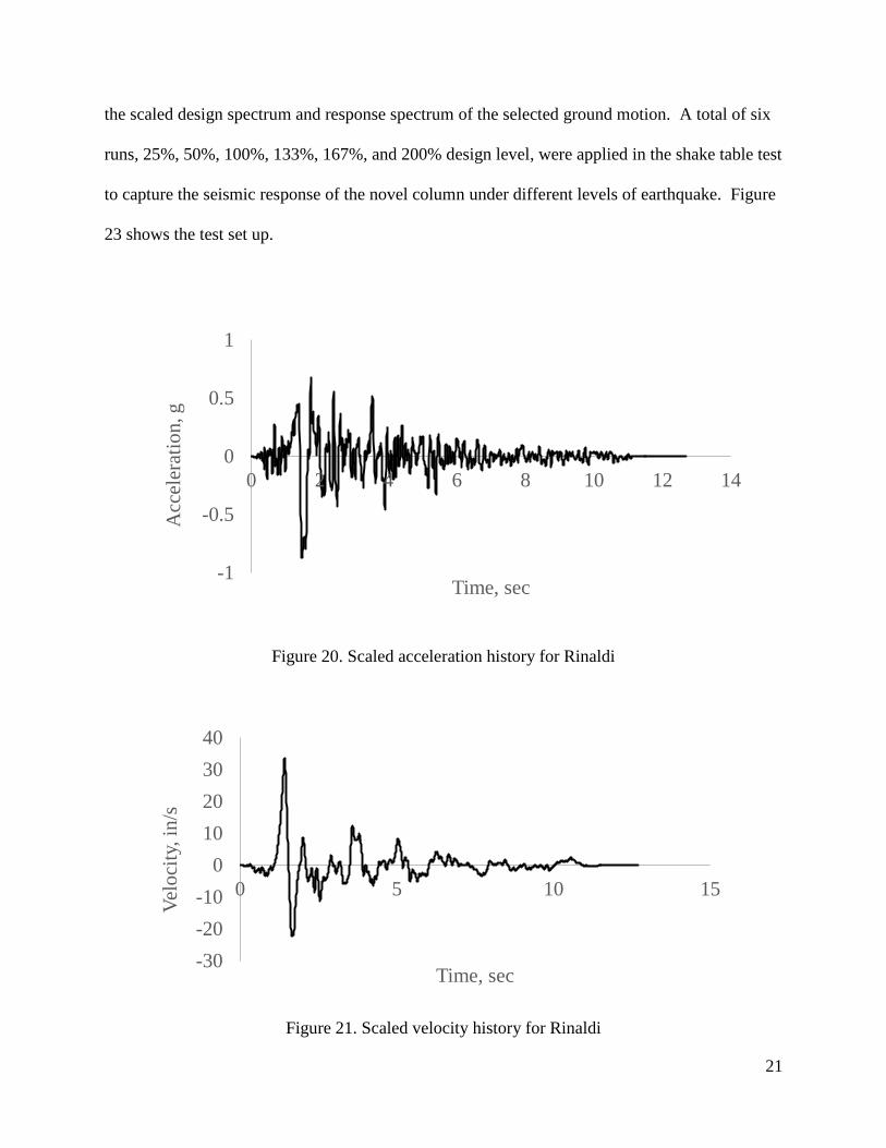
displacements in conventional reinforced concrete columns. The time scaled acceleration and
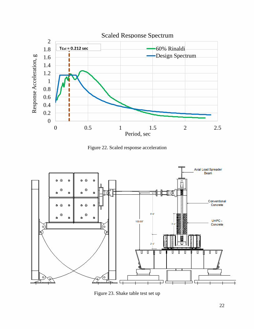
velocity histories for this near-fault motion are shown in Fig. 20 and Fig. 21. Figure 22 shows
21
the scaled design spectrum and response spectrum of the selected ground motion. A total of six
runs, 25%, 50%, 100%, 133%, 167%, and 200% design level, were applied in the shake table test
to capture the seismic response of the novel column under different levels of earthquake. Figure
23 shows the test set up.
Figure 20. Scaled acceleration history for Rinaldi
Figure 21. Scaled velocity history for Rinaldi
-1
-0.5
0
0.5
1
0 2 4 6 8 10 12 14
Acc
eler
atio
n, g
Time, sec
-30
-20
-10
0
10
20
30
40
0 5 10 15
Vel
oci
ty, in
/s
Time, sec
22
Figure 22. Scaled response acceleration
Figure 23. Shake table test set up
0
0.2
0.4
0.6
0.8
1
1.2
1.4
1.6
1.8
2
0 0.5 1 1.5 2 2.5
Res
po
nse
Acc
eler
atio
n, g
Period, sec
60% Rinaldi
Design Spectrum
Scaled Response Spectrum
Tcol = 0.212 sec
23
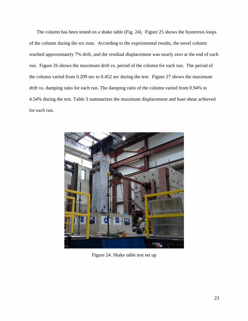
The column has been tested on a shake table (Fig. 24). Figure 25 shows the hysteresis loops
of the column during the six runs. According to the experimental results, the novel column
reached approximately 7% drift, and the residual displacement was nearly zero at the end of each
run. Figure 26 shows the maximum drift vs. period of the column for each run. The period of
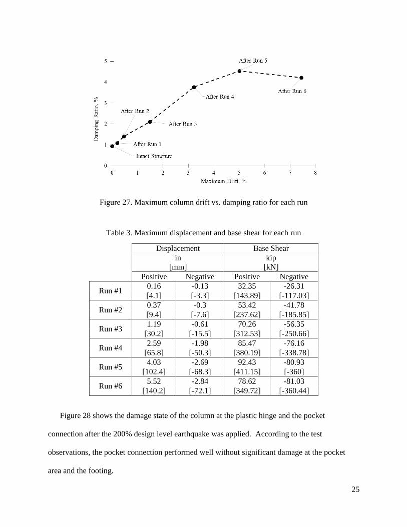
the column varied from 0.209 sec to 0.452 sec during the test. Figure 27 shows the maximum
drift vs. damping ratio for each run. The damping ratio of the column varied from 0.94% to
4.54% during the test. Table 3 summarizes the maximum displacement and base shear achieved
for each run.
Figure 24. Shake table test set up

24
Figure 25. Hysteresis loops of the novel column
Figure 26. Maximum column drift vs. period for each run
25
Figure 27. Maximum column drift vs. damping ratio for each run
Table 3. Maximum displacement and base shear for each run
Displacement Base Shear
in kip
[mm] [kN]
Positive Negative Positive Negative
Run #1 0.16 -0.13 32.35 -26.31
[4.1] [-3.3] [143.89] [-117.03]
Run #2 0.37 -0.3 53.42 -41.78
[9.4] [-7.6] [237.62] [-185.85]
Run #3 1.19 -0.61 70.26 -56.35
[30.2] [-15.5] [312.53] [-250.66]
Run #4 2.59 -1.98 85.47 -76.16
[65.8] [-50.3] [380.19] [-338.78]
Run #5 4.03 -2.69 92.43 -80.93
[102.4] [-68.3] [411.15] [-360]
Run #6 5.52 -2.84 78.62 -81.03
[140.2] [-72.1] [349.72] [-360.44]
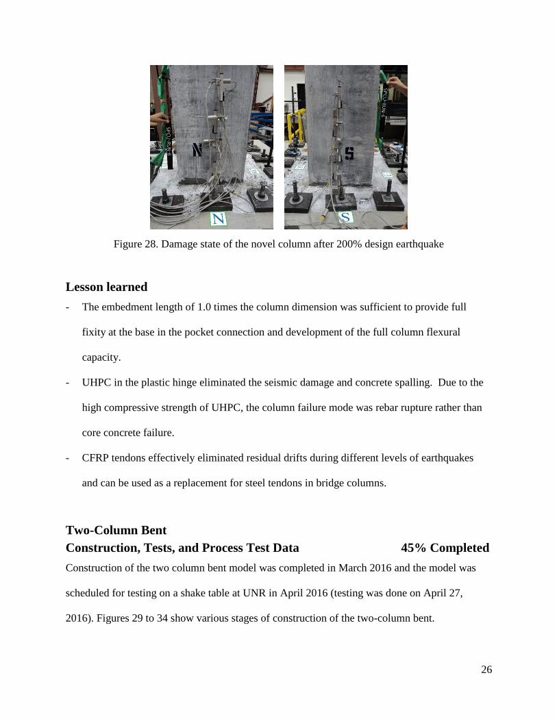
Figure 28 shows the damage state of the column at the plastic hinge and the pocket
connection after the 200% design level earthquake was applied. According to the test
observations, the pocket connection performed well without significant damage at the pocket
area and the footing.
26
Figure 28. Damage state of the novel column after 200% design earthquake
Lesson learned
- The embedment length of 1.0 times the column dimension was sufficient to provide full
fixity at the base in the pocket connection and development of the full column flexural
capacity.
- UHPC in the plastic hinge eliminated the seismic damage and concrete spalling. Due to the
high compressive strength of UHPC, the column failure mode was rebar rupture rather than
core concrete failure.
- CFRP tendons effectively eliminated residual drifts during different levels of earthquakes
and can be used as a replacement for steel tendons in bridge columns.
Two-Column Bent
Construction, Tests, and Process Test Data 45% Completed
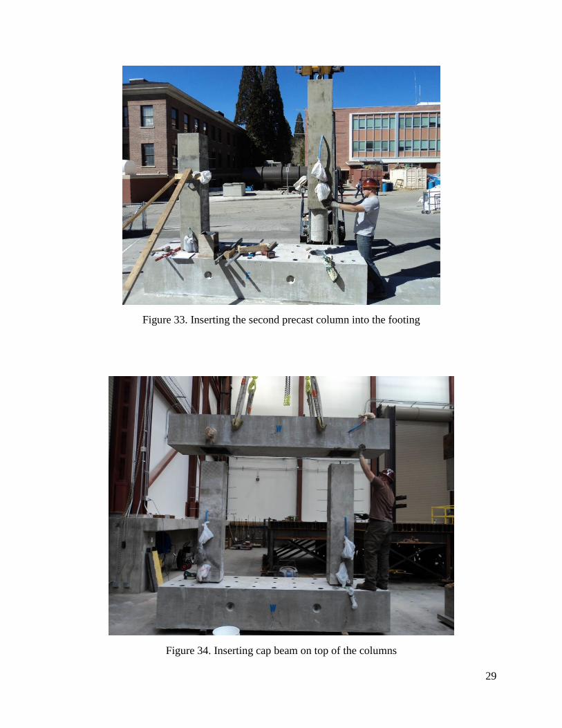
Construction of the two column bent model was completed in March 2016 and the model was
scheduled for testing on a shake table at UNR in April 2016 (testing was done on April 27,
2016). Figures 29 to 34 show various stages of construction of the two-column bent.

27
Figure 29. Cap beam construction and pocket for columns

28
Figure 30. Footing and pockets for columns
Figure 31. Column reinforcement cage
Figure 32. Placing UHPC/ECC in plastic hinge zone simultaneously with concrete
29
Figure 33. Inserting the second precast column into the footing
Figure 34. Inserting cap beam on top of the columns
30
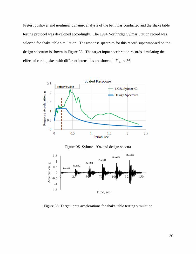
Pretest pushover and nonlinear dynamic analysis of the bent was conducted and the shake table
testing protocol was developed accordingly. The 1994 Northridge Sylmar Station record was
selected for shake table simulation. The response spectrum for this record superimposed on the
design spectrum is shown in Figure 35. The target input acceleration records simulating the
effect of earthquakes with different intensities are shown in Figure 36.
Figure 35. Sylmar 1994 and design spectra
Figure 36. Target input accelerations for shake table testing simulation
31
Task 5 – Conduct analytical studies of the column and pier models Pending
Task 6 – Develop design method and numerical examples Pending
Task 7 – Summarize the investigation and the results in a draft final report
Pending
A.5 Expected Results and Specific Deliverables
The results from this study are expected to determine the feasibility and seismic performance
of bridge piers incorporating precast, post-tensioned columns with unbonded CFRP tendons and
damage-free plastic hinges. The experimental and parametric analytical results will reveal the
effects of important parameters and their optimized combination. Specifically, the results are
expected to provide information on the following aspects of seismic behavior and design of these
types of piers:
a) The appropriate embedment length of precast square columns in pocket connections in
cap beams and footings based on column geometric and strength properties.
b) The optimized length of the UHPC segments of columns.
c) The shear performance of UHPC segments.
d) The effectiveness of CFRP tendons and their anchorage.
e) The effectiveness and relative merit of ECC and Ductal in reducing column earthquake
damage.
f) Optimized level of PT force based on column geometric and strength characteristics.
The deliverables from this study will consist of:
a) Details of design, construction process, and testing of the pier models.

32
b) Experimental data on all transducers for different levels of earthquakes.
c) Pretest and post-test analytical procedures and results.
d) Interpretation of the effect of different parameters that will be investigated through the
experimental and analytical studies.
e) Practical design procedures and illustrative design examples.
The final project report including details of the study and an executive summary.