Embed Size (px)
Citation preview
EURASIP Journal onEmbedded Systems
Chen et al. EURASIP Journal on Embedded Systems (2017) 2017:19 DOI 10.1186/s13639-017-0069-7
RESEARCH Open Access
Design and evaluation of medicalultrasonic adaptive beamforming algorithmimplementation on heterogeneous embeddedcomputing platformJunying Chen* , Jinhui Chen and Huaqing Min
Abstract
Medical ultrasonic imaging has been utilized in a variety of clinical diagnoses for many years. Recently, because of theneeds of portable and mobile medical ultrasonic diagnoses, the development of real-time medical ultrasonic imagingalgorithms on embedded computing platforms is a rising research direction. Typically, delay-and-sum beamformingalgorithm is implemented on embedded medical ultrasonic scanners. Such algorithm is the easiest to implement atreal-time frame rate, but the image quality of this algorithm is not high enough for complicated diagnostic cases. As aresult, minimum-variance adaptive beamforming algorithm for medical ultrasonic imaging is considered in this paper,which shows much higher image quality than that of delay-and-sum beamforming algorithm. However, minimum-variance adaptive beamforming algorithm is a complicated algorithm with O(n3) computational complexity.Consequently, it is not easy to implement such algorithm on embedded computing platform at real-time frame rate.On the other hand, GPU is a well-known parallel computing platform for image processing. Therefore, embeddedGPU computing platform is considered as a potential real-time implementation platform of minimum-variancebeamforming algorithm in this paper. By applying the described effective implementation strategies, the GPUimplementation of minimum-variance beamforming algorithm performed more than 100 times faster than the ARMimplementation on the same heterogeneous embedded platform. Furthermore, platform power consumptions,computation energy efficiency, and platform cost efficiency of the experimental heterogeneous embedded platformswere also evaluated, which demonstrated that the investigated heterogeneous embedded computing platformswere suitable for real-time portable or mobile high-quality medical ultrasonic imaging device constructions.
Keywords: Embedded GPU implementation, Medical ultrasonic adaptive beamforming, High-performancecomputing
1 IntroductionThere are several useful medical imaging modalities forclinical diagnoses, which are radiography [1], magneticresonance imaging [2], nuclear imaging [3], ultrasonicimaging [4], and computed tomography [5]. Among thementioned medical imaging modalities, medical ultra-sonic imaging is a very common imaging techniquewhich has been widely applied to a vast range of clinical
*Correspondence: [email protected] Key Laboratory of Robotics and Intelligent Software, School ofSoftware Engineering, South China University of Technology, Guangzhou,China
diagnoses for many years [6]. Medical ultrasonic imaginghas overwhelming advantages over other medical imag-ing modalities, such as real-time imaging at a smoothvideo frame rate, high safety without electromagneticradiation, and relatively low cost as compared to othermedical imaging modalities [7]. Therefore, medical ultra-sonic imaging is usually utilized to observe heart move-ments [8], fetal developments [9], blood flows [10], andso on. Recently, as the needs for portable and mobilemedical ultrasonic diagnoses increase, the developmentof medical ultrasonic imaging algorithms on embeddedcomputing platforms is a rising research direction. Thekey evaluation feature of an embedded medical ultrasonic
© The Author(s). 2017 Open Access This article is distributed under the terms of the Creative Commons Attribution 4.0International License (http://creativecommons.org/licenses/by/4.0/), which permits unrestricted use, distribution, andreproduction in any medium, provided you give appropriate credit to the original author(s) and the source, provide a link to theCreative Commons license, and indicate if changes were made.
Chen et al. EURASIP Journal on Embedded Systems (2017) 2017:19 Page 2 of 12
imaging algorithm implementation is its real-time imag-ing capability. A medical ultrasonic imaging algorithmcan be used for real-world clinical diagnostic applicationsonly if its implementation can run at a real-time videoframe rate.Delay-and-sum (DAS) beamforming [6] is the most
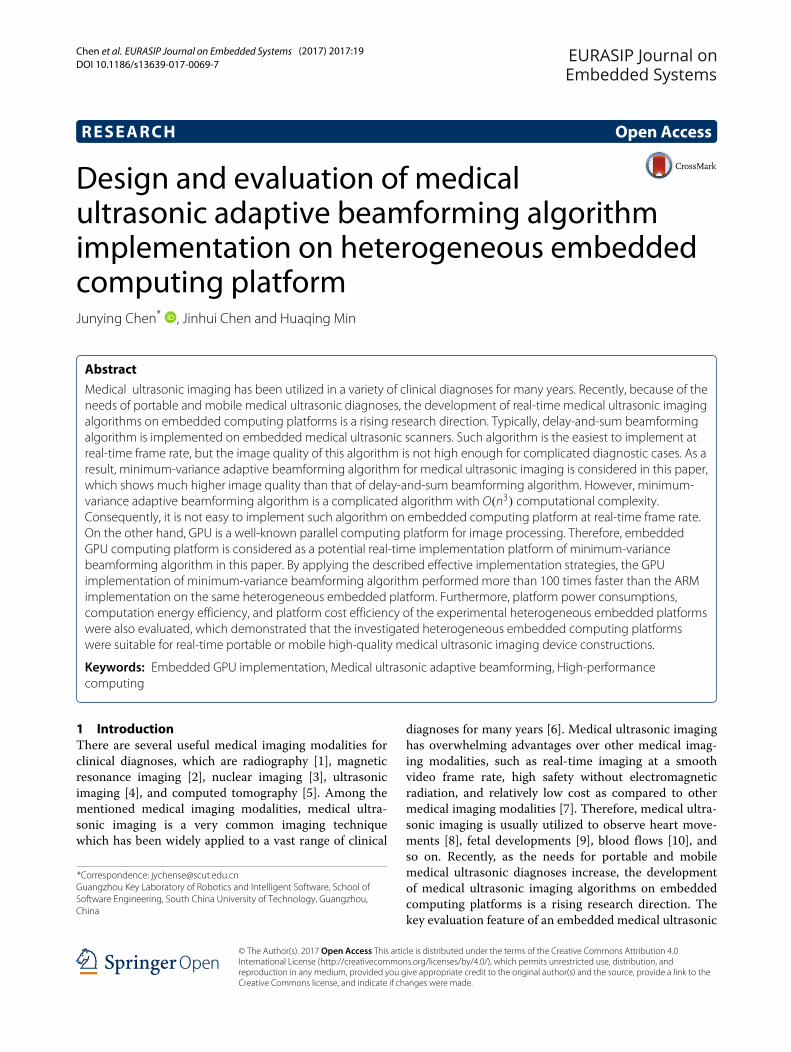
widespread imaging algorithm among various medicalultrasonic imaging algorithms, which is also the easi-est to implement at real-time frame rate. But the imagequality of DAS algorithm is not high enough for compli-cated diagnostic cases. On the other hand, high-qualitymedical ultrasonic imaging algorithms (e.g., minimum-variance (MV) adaptive beamforming algorithm [11], syn-thetic aperture imaging algorithm [12]) provide muchbetter image quality, as compared to DAS beamformingalgorithm, which can present more anatomical details forcomplicated diagnostic cases. For example, Fig. 1 illus-trates the advantage of MV adaptive beamforming overDAS beamforming. The example used field II simulator[13] to generate the simulated imaging input data. Field IIsimulator is a widespread tool to generate reliable medicalultrasonic imaging input data, especially for quantitativeevaluation of the output image quality and verification ofimaging algorithm correctness, which is its major benefitover real scenario. As shown in Fig. 1, DAS beamform-ing failed to resolve the two very close point targets at30-mm imaging depth, making the two points look likea short line instead. But on the other hand, the two veryclose point targets at 30-mm imaging depth were clearlydistinguished usingMV adaptive beamforming algorithm.However, these high-quality imaging algorithms are
computationally demanding and difficult to implementin real-time, especially on embedded platforms with lim-ited computing resources. The real-time implementa-tion of MV adaptive beamforming is challenging, whosecomputational complexity is O(n3) in sequential imple-mentation [14]. Among various embedded computingplatforms, field-programmable gate arrays (FPGAs) are
20 mm
30 mm
25 mm
0.5 mm
DAS MV
20
25
30
Imag
ing
De
pth
[mm
]
-4 -2 0 2 4 Lateral Distance [mm]
-4 -2 0 2 4 Lateral Distance [mm]
Fig. 1 Results of imaging two very close point targets at differentimaging depths using DAS beamforming algorithm and MV adaptivebeamforming algorithm
good potential development platforms to implement real-time medical ultrasonic imaging algorithms. However, anFPGA platform with sufficient computational resourcesto implement a regular high-quality medical ultrasonicimaging algorithm at real-time video frame rate is usuallyof high price. Hence, in order to reduce the implemen-tation cost of a portable or mobile medical ultrasonicimaging device, alternative high-performance embeddedcomputing platform with relatively lower implementationcost is required. As a result, the heterogeneous embed-ded computing platforms with high-performance graph-ics processing units (GPUs) and advanced RISC machine(ARM) processors will be investigated in this paper.In this paper, the implementation ofMV adaptive beam-
forming algorithm on high-performance embedded GPUcomputing platform will be discussed. The implementa-tion strategies for a high-performance GPU on a hetero-geneous embedded computing platform will be described,and the performance of the GPU implementation andits ARM processor counterpart on the same embeddedcomputing platform will be evaluated. The performancefeatures evaluated in this paper will include the algorithmcomputing speed, the computation energy efficiency, andthe platform cost efficiency. The following section willinterpret the detailed sequential calculation steps of themedical ultrasonic MV adaptive beamforming algorithm.Then, the implementation design of the MV adaptivebeamforming algorithm on the embedded GPU comput-ing platform will be described in Section 3. Section 4will illustrate the experimental setup and the performanceevaluations of the embedded implementations. Finally, thepaper concludes in Section 5.
2 Medical ultrasonic adaptive beamformingsequential calculation
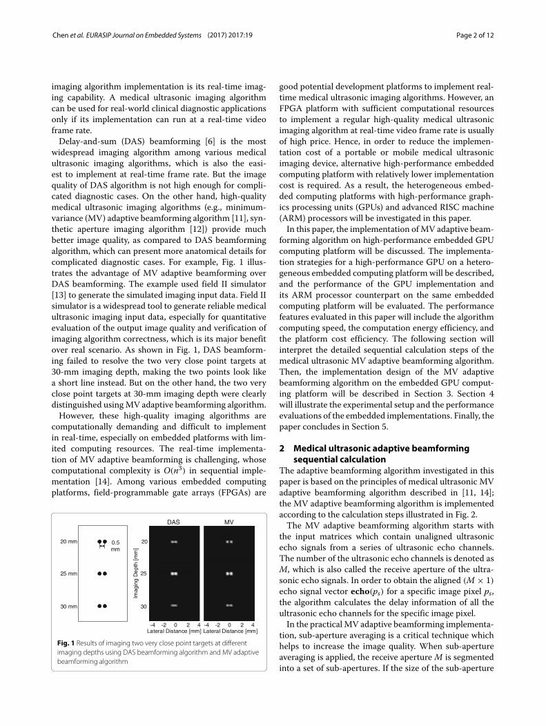
The adaptive beamforming algorithm investigated in thispaper is based on the principles of medical ultrasonic MVadaptive beamforming algorithm described in [11, 14];the MV adaptive beamforming algorithm is implementedaccording to the calculation steps illustrated in Fig. 2.The MV adaptive beamforming algorithm starts with
the input matrices which contain unaligned ultrasonicecho signals from a series of ultrasonic echo channels.The number of the ultrasonic echo channels is denoted asM, which is also called the receive aperture of the ultra-sonic echo signals. In order to obtain the aligned (M × 1)echo signal vector echo(ps) for a specific image pixel ps,the algorithm calculates the delay information of all theultrasonic echo channels for the specific image pixel.In the practical MV adaptive beamforming implementa-
tion, sub-aperture averaging is a critical technique whichhelps to increase the image quality. When sub-apertureaveraging is applied, the receive aperture M is segmentedinto a set of sub-apertures. If the size of the sub-aperture
Chen et al. EURASIP Journal on Embedded Systems (2017) 2017:19 Page 3 of 12
Input matrices containing unaligned echo signals from a
series of ultrasonic echo channels
Algorithm input
Calculate the delays in the ultrasonic echo channels for a specific pixel, obtain an aligned
echo signal vector echo(ps)
Apply sub-aperture averaging to echo(ps), obtain echosubk(ps)
(k=0, 1, …, M-L)
Calculate covariance matrix for the specific pixel, obtain Covar(ps)
Calculate adaptive weight vector for the specific pixel, obtain w(ps)
Calculate amplitude estimate value for the specific pixel, obtain v(ps)
Algorithm outputFig. 2Medical ultrasonic MV adaptive beamforming algorithmcalculation steps (Calculation steps repeat until all pixel amplitudeestimate values are obtained)
is L, which means there are L consecutive ultrasonic echosignal channels within the sub-aperture, (M − L + 1)sub-apertures are constructed. As a result, the alignedultrasonic echo signal vector echo(ps) is segmented into(M − L + 1) sub-aperture echo signal vectorsechosubk(ps)(k = 0, 1, . . . ,M − L), where echosubk(ps)is a (L × 1) vector of input ultrasonic echo signals in
kth sub-aperture, i.e., echosubk(ps) is the assemble ofkth to (k + L − 1)th elements of echo(ps) vector. Then,the covariance matrix calculation with sub-apertureaveraging for a specific image pixel is expressed as
Covar(ps) =∑M−L
k=0 echosubk(ps)echoHsubk(ps)M − L + 1
. (1)
The calculation of adaptive apodization weight vectoris conducted after the covariance matrix Covar(ps) isobtained, which is calculated as
w(ps) = Covar−1(ps)aaHCovar−1(ps)a
, (2)
where a is a steering vector with all ones, which is becausethe ultrasonic echo signals used for covariance matrixcalculation are already delayed and aligned.Finally, when the adaptive apodization weight vector
w(ps) is ready, the amplitude estimate value of the specificimage pixel ps is obtained by
v(ps) = 1M − L + 1
M−L∑
k=0wH(ps)echosubk(ps). (3)
The pixel amplitude estimate value v(ps) is the output ofthe MV adaptive beamforming algorithm. The calculationsteps repeat until all the pixel amplitude estimate values ofthe whole image are obtained.
3 Implementation design on embedded GPUcomputing platform
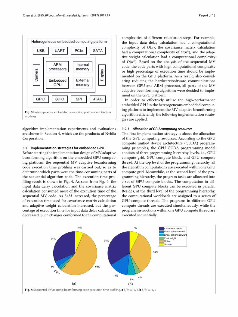
3.1 Heterogeneous embedded computing platformAlthough MV adaptive beamforming algorithm outputshigh-quality medical ultrasonic images, it is computa-tionally demanding. The high computational complex-ity of MV adaptive beamforming algorithm hinders MValgorithm being implemented in real-time on conven-tional embedded computing platforms, such as conven-tional ARM processors. Therefore, the implementation ofMV adaptive beamforming algorithm on heterogeneousembedded computing platform with high-performanceGPU is explored in this paper, so as to validate the real-time imaging capability of MV adaptive beamformingalgorithm on embedded platforms.The symbolic architecture modules of the heteroge-
neous embedded computing platform is illustrated inFig. 3. As shown in Fig. 3, the ARM processors and theembedded GPU are within one single embedded pro-cessing chip, as well as the internal memory and theexternal memory modules. There are plenty of periph-erals on the heterogeneous embedded computing plat-form, such as camera input module, display output mod-ule, USB, GPIO, and other common peripheral connec-tor modules. The heterogeneous embedded computingplatforms investigated in the MV adaptive beamforming
Chen et al. EURASIP Journal on Embedded Systems (2017) 2017:19 Page 4 of 12
Heterogeneous embedded computing platform
USB UART
GPIO SDIO SPI
PCIe
Ca
mer
a
Dis
pla
y
SATA
JTAG
ARM processors
Embedded GPU
Internal memory
External memory
Fig. 3 Heterogeneous embedded computing platform architecturemodules
algorithm implementation experiments and evaluationsare shown in Section 4, which are the products of NvidiaCorporation.
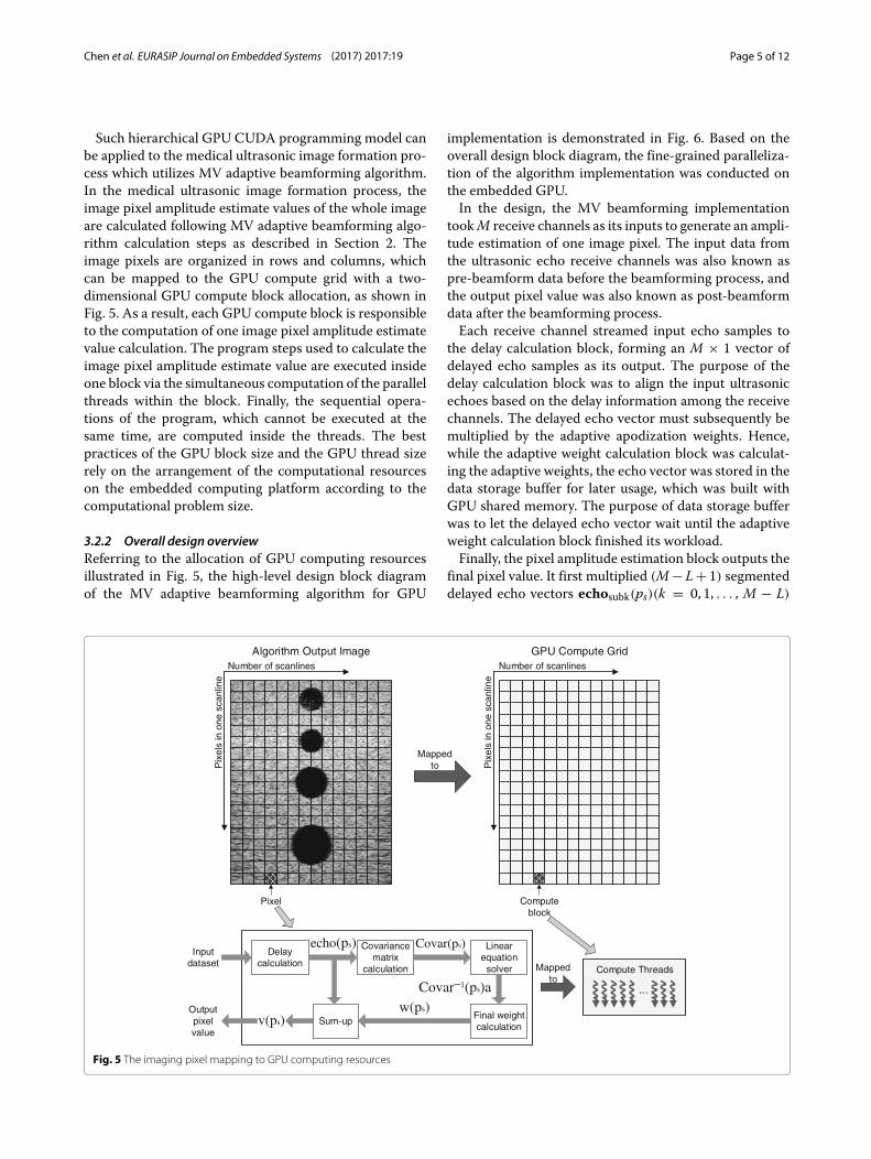
3.2 Implementation strategies for embedded GPUBefore starting the implementation design ofMV adaptivebeamforming algorithm on the embedded GPU comput-ing platform, the sequential MV adaptive beamformingcode execution time profiling was carried out, so as todetermine which parts were the time-consuming parts ofthe sequential algorithm code. The execution time pro-filing result is shown in Fig. 4. As seen from Fig. 4, theinput data delay calculation and the covariance matrixcalculation consumed most of the execution time of thesequential MV code. As L/M increased, the percentageof execution time used for covariance matrix calculationand adaptive weight calculation increased, but the per-centage of execution time for input data delay calculationdecreased. Such changes conformed to the computational
complexities of different calculation steps. For example,the input data delay calculation had a computationalcomplexity of O(n), the covariance matrix calculationhad a computational complexity of O(n2), and the adap-tive weight calculation had a computational complexityof O(n3). Based on the analysis of the sequential MVcode, the code parts with high computational complexityor high percentage of execution time should be imple-mented on the GPU platform. As a result, also consid-ering reducing the hardware/software communicationsbetween GPU and ARM processor, all parts of the MVadaptive beamforming algorithm were decided to imple-ment on the GPU platform.In order to effectively utilize the high-performance
embedded GPU in the heterogeneous embedded comput-ing platform to implement the MV adaptive beamformingalgorithm efficiently, the following implementation strate-gies are applied.
3.2.1 Allocation of GPU computing resourcesThe first implementation strategy is about the allocationof the GPU computing resources. According to the GPUcompute unified device architecture (CUDA) program-ming principles, the GPU CUDA programming modelconsists of three programming hierarchy levels, i.e., GPUcompute grid, GPU compute block, and GPU computethread. At the top level of the programming hierarchy, allthe algorithm computations are executed within one GPUcompute grid. Meanwhile, at the second level of the pro-gramming hierarchy, the program tasks are allocated intoa set of GPU compute blocks. The computation in dif-ferent GPU compute blocks can be executed in parallel.Besides, at the third level of the programming hierarchy,the computational workloads are assigned to a series ofGPU compute threads. The programs in different GPUcompute threads are executed simultaneously, while theprogram instructions within one GPU compute thread areexecuted sequentially.
Fig. 4 Sequential MV adaptive beamforming code execution time profiling. a L/M = 1/4. b L/M = 1/2
Chen et al. EURASIP Journal on Embedded Systems (2017) 2017:19 Page 5 of 12
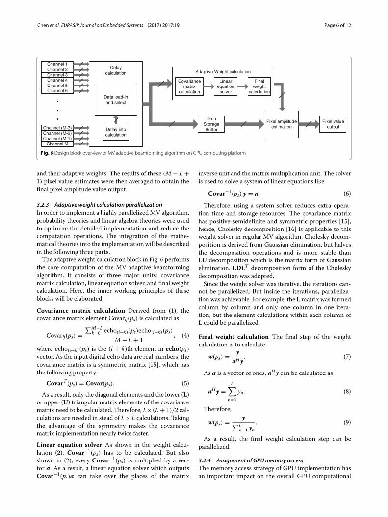
Such hierarchical GPU CUDA programming model canbe applied to the medical ultrasonic image formation pro-cess which utilizes MV adaptive beamforming algorithm.In the medical ultrasonic image formation process, theimage pixel amplitude estimate values of the whole imageare calculated following MV adaptive beamforming algo-rithm calculation steps as described in Section 2. Theimage pixels are organized in rows and columns, whichcan be mapped to the GPU compute grid with a two-dimensional GPU compute block allocation, as shown inFig. 5. As a result, each GPU compute block is responsibleto the computation of one image pixel amplitude estimatevalue calculation. The program steps used to calculate theimage pixel amplitude estimate value are executed insideone block via the simultaneous computation of the parallelthreads within the block. Finally, the sequential opera-tions of the program, which cannot be executed at thesame time, are computed inside the threads. The bestpractices of the GPU block size and the GPU thread sizerely on the arrangement of the computational resourceson the embedded computing platform according to thecomputational problem size.
3.2.2 Overall design overviewReferring to the allocation of GPU computing resourcesillustrated in Fig. 5, the high-level design block diagramof the MV adaptive beamforming algorithm for GPU
implementation is demonstrated in Fig. 6. Based on theoverall design block diagram, the fine-grained paralleliza-tion of the algorithm implementation was conducted onthe embedded GPU.In the design, the MV beamforming implementation
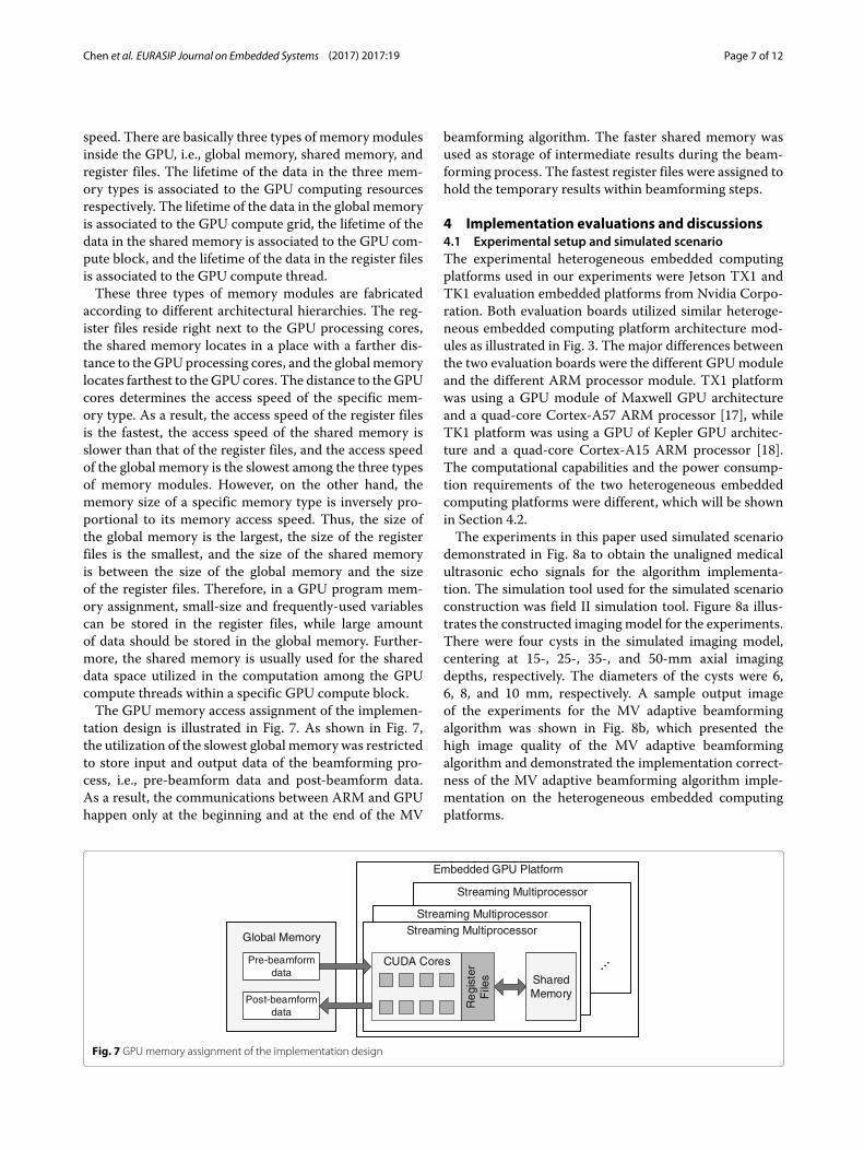
tookM receive channels as its inputs to generate an ampli-tude estimation of one image pixel. The input data fromthe ultrasonic echo receive channels was also known aspre-beamform data before the beamforming process, andthe output pixel value was also known as post-beamformdata after the beamforming process.Each receive channel streamed input echo samples to
the delay calculation block, forming an M × 1 vector ofdelayed echo samples as its output. The purpose of thedelay calculation block was to align the input ultrasonicechoes based on the delay information among the receivechannels. The delayed echo vector must subsequently bemultiplied by the adaptive apodization weights. Hence,while the adaptive weight calculation block was calculat-ing the adaptive weights, the echo vector was stored in thedata storage buffer for later usage, which was built withGPU shared memory. The purpose of data storage bufferwas to let the delayed echo vector wait until the adaptiveweight calculation block finished its workload.Finally, the pixel amplitude estimation block outputs the
final pixel value. It first multiplied (M− L+ 1) segmenteddelayed echo vectors echosubk(ps)(k = 0, 1, . . . , M − L)
Number of scanlines
Pix
els
in o
ne s
canl
ine
Pix
els
in o
ne s
canl
ine
Algorithm Output Image
Pixel
Number of scanlines
GPU Compute Grid
Compute block
Compute Threads
Delay calculation
echo(ps) Covar(ps)
v(ps)w(ps)
Covariance matrix
calculation
Linear equation
solver
Final weight calculation
Input dataset
...
Sum-upOutput pixel value
Mapped to
Mapped to
Covar−1(ps)a
Fig. 5 The imaging pixel mapping to GPU computing resources
Chen et al. EURASIP Journal on Embedded Systems (2017) 2017:19 Page 6 of 12
Channel (M-3)Channel (M-2)Channel (M-1)
Channel M
Channel 1Channel 2Channel 3Channel 4Channel 5Channel 6
Delaycalculation Adaptive Weight calculation
Covariance matrix
calculation
Linearequation
solver
Final weight
calculation
Pixel amplitude estimation
Pixel value outputDelay info
calculation
Data load-inand select
Data Storage Buffer
Fig. 6 Design block overview of MV adaptive beamforming algorithm on GPU computing platform
and their adaptive weights. The results of these (M − L +1) pixel value estimates were then averaged to obtain thefinal pixel amplitude value output.
3.2.3 Adaptive weight calculation parallelizationIn order to implement a highly parallelizedMV algorithm,probability theories and linear algebra theories were usedto optimize the detailed implementation and reduce thecomputation operations. The integration of the mathe-matical theories into the implementation will be describedin the following three parts.The adaptive weight calculation block in Fig. 6 performs
the core computation of the MV adaptive beamformingalgorithm. It consists of three major units: covariancematrix calculation, linear equation solver, and final weightcalculation. Here, the inner working principles of theseblocks will be elaborated.
Covariance matrix calculation Derived from (1), thecovariance matrix element Covarij(ps) is calculated as
Covarij(ps) =∑M−L
k=0 echo(i+k)(ps)echo(j+k)(ps)M − L + 1
, (4)
where echo(i+k)(ps) is the (i + k)th element in echo(ps)vector. As the input digital echo data are real numbers, thecovariance matrix is a symmetric matrix [15], which hasthe following property:
CovarT (ps) = Covar(ps). (5)
As a result, only the diagonal elements and the lower (L)or upper (U) triangular matrix elements of the covariancematrix need to be calculated. Therefore, L×(L + 1)/2 cal-culations are needed in stead of L×L calculations. Takingthe advantage of the symmetry makes the covariancematrix implementation nearly twice faster.
Linear equation solver As shown in the weight calcu-lation (2), Covar−1(ps) has to be calculated. But alsoshown in (2), every Covar−1(ps) is multiplied by a vec-tor a. As a result, a linear equation solver which outputsCovar−1(ps)a can take over the places of the matrix
inverse unit and the matrix multiplication unit. The solveris used to solve a system of linear equations like:
Covar−1(ps) y = a. (6)
Therefore, using a system solver reduces extra opera-tion time and storage resources. The covariance matrixhas positive-semidefinite and symmetric properties [15],hence, Cholesky decomposition [16] is applicable to thisweight solver in regular MV algorithm. Cholesky decom-position is derived from Gaussian elimination, but halvesthe decomposition operations and is more stable thanLU decomposition which is the matrix form of Gaussianelimination. LDLT decomposition form of the Choleskydecomposition was adopted.Since the weight solver was iterative, the iterations can-
not be parallelized. But inside the iterations, paralleliza-tion was achievable. For example, the Lmatrix was formedcolumn by column and only one column in one itera-tion, but the element calculations within each column ofL could be parallelized.
Final weight calculation The final step of the weightcalculation is to calculate
w(ps) = yaHy
. (7)
As a is a vector of ones, aHy can be calculated as
aHy =L∑
n=1yn. (8)
Therefore,
w(ps) = y∑L
n=1 yn. (9)
As a result, the final weight calculation step can beparallelized.
3.2.4 Assignment of GPUmemory accessThe memory access strategy of GPU implementation hasan important impact on the overall GPU computational
Chen et al. EURASIP Journal on Embedded Systems (2017) 2017:19 Page 7 of 12
speed. There are basically three types of memory modulesinside the GPU, i.e., global memory, shared memory, andregister files. The lifetime of the data in the three mem-ory types is associated to the GPU computing resourcesrespectively. The lifetime of the data in the global memoryis associated to the GPU compute grid, the lifetime of thedata in the shared memory is associated to the GPU com-pute block, and the lifetime of the data in the register filesis associated to the GPU compute thread.These three types of memory modules are fabricated
according to different architectural hierarchies. The reg-ister files reside right next to the GPU processing cores,the shared memory locates in a place with a farther dis-tance to the GPU processing cores, and the global memorylocates farthest to the GPU cores. The distance to the GPUcores determines the access speed of the specific mem-ory type. As a result, the access speed of the register filesis the fastest, the access speed of the shared memory isslower than that of the register files, and the access speedof the global memory is the slowest among the three typesof memory modules. However, on the other hand, thememory size of a specific memory type is inversely pro-portional to its memory access speed. Thus, the size ofthe global memory is the largest, the size of the registerfiles is the smallest, and the size of the shared memoryis between the size of the global memory and the sizeof the register files. Therefore, in a GPU program mem-ory assignment, small-size and frequently-used variablescan be stored in the register files, while large amountof data should be stored in the global memory. Further-more, the shared memory is usually used for the shareddata space utilized in the computation among the GPUcompute threads within a specific GPU compute block.The GPU memory access assignment of the implemen-
tation design is illustrated in Fig. 7. As shown in Fig. 7,the utilization of the slowest global memory was restrictedto store input and output data of the beamforming pro-cess, i.e., pre-beamform data and post-beamform data.As a result, the communications between ARM and GPUhappen only at the beginning and at the end of the MV
beamforming algorithm. The faster shared memory wasused as storage of intermediate results during the beam-forming process. The fastest register files were assigned tohold the temporary results within beamforming steps.
4 Implementation evaluations and discussions4.1 Experimental setup and simulated scenarioThe experimental heterogeneous embedded computingplatforms used in our experiments were Jetson TX1 andTK1 evaluation embedded platforms from Nvidia Corpo-ration. Both evaluation boards utilized similar heteroge-neous embedded computing platform architecture mod-ules as illustrated in Fig. 3. The major differences betweenthe two evaluation boards were the different GPUmoduleand the different ARM processor module. TX1 platformwas using a GPU module of Maxwell GPU architectureand a quad-core Cortex-A57 ARM processor [17], whileTK1 platform was using a GPU of Kepler GPU architec-ture and a quad-core Cortex-A15 ARM processor [18].The computational capabilities and the power consump-tion requirements of the two heterogeneous embeddedcomputing platforms were different, which will be shownin Section 4.2.The experiments in this paper used simulated scenario
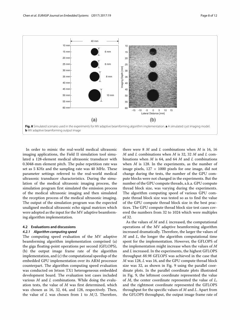
demonstrated in Fig. 8a to obtain the unaligned medicalultrasonic echo signals for the algorithm implementa-tion. The simulation tool used for the simulated scenarioconstruction was field II simulation tool. Figure 8a illus-trates the constructed imagingmodel for the experiments.There were four cysts in the simulated imaging model,centering at 15-, 25-, 35-, and 50-mm axial imagingdepths, respectively. The diameters of the cysts were 6,6, 8, and 10 mm, respectively. A sample output imageof the experiments for the MV adaptive beamformingalgorithm was shown in Fig. 8b, which presented thehigh image quality of the MV adaptive beamformingalgorithm and demonstrated the implementation correct-ness of the MV adaptive beamforming algorithm imple-mentation on the heterogeneous embedded computingplatforms.
Embedded GPU Platform
Streaming Multiprocessor
Streaming MultiprocessorStreaming Multiprocessor
CUDA Cores
Shared Memory
Global Memory
Pre-beamform data
Post-beamform data
Re
gist
er
File
s
Fig. 7 GPU memory assignment of the implementation design
Chen et al. EURASIP Journal on Embedded Systems (2017) 2017:19 Page 8 of 12
10 mm
20 mm
30 mm
40 mm
50 mm
60 mm
25 mm
40 mm
6 mm15 mm
35 mm
45 mm
55 mm
6 mm
8 mm
10 mm
(a) (b)
10
20
30
40
50
60
25
15
35
45
55
Imag
ing
Dep
th [
mm
]
Lateral Distance [mm]-15 -10 -5 0 5 10 15
Fig. 8 Simulated scenario used in the experiments for MV adaptive beamforming algorithm implementation. a A simulated cyst imaging model.bMV adaptive beamforming output image
In order to mimic the real-world medical ultrasonicimaging applications, the Field II simulation tool simu-lated a 128-element medical ultrasonic transducer with0.3048-mm element pitch. The pulse repetition rate wasset as 5 KHz and the sampling rate was 40 MHz. Theseparameter settings referred to the real-world medicalultrasonic transducer characteristics. During the simu-lation of the medical ultrasonic imaging process, thesimulation program first simulated the emission processof the medical ultrasonic imaging and then simulatedthe reception process of the medical ultrasonic imaging.The output of the simulation program was the expectedunaligned medical ultrasonic echo signal matrices whichwere adopted as the input for theMV adaptive beamform-ing algorithm implementation.
4.2 Evaluations and discussions4.2.1 Algorithm computing speedThe computing speed evaluation of the MV adaptivebeamforming algorithm implementation comprised (a)the giga floating-point operations per second (GFLOPS),(b) the output image frame rate of the algorithmimplementation, and (c) the computational speedup of theembedded GPU implementation over its ARM processorcounterpart. The algorithm computing speed evaluationwas conducted on Jetson TX1 heterogeneous embeddeddevelopment board. The evaluation test cases includedvarious M and L combinations. While doing the evalu-ation tests, the value of M was first determined, whichwas chosen as 16, 32, 64, and 128, respectively. Then,the value of L was chosen from 1 to M/2. Therefore,
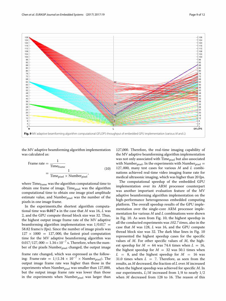
there were 8 M and L combinations when M is 16, 16M and L combinations when M is 32, 32 M and L com-binations when M is 64, and 64 M and L combinationswhen M is 128. In the experiments, as the number ofimage pixels, 127 × 1000 pixels for one image, did notchange during the tests, the number of the GPU com-pute blocks were not changed in the experiments. But thenumber of the GPU compute threads, a.k.a. GPU computethread block size, was varying during the experiments.The algorithm computing speed of various GPU com-pute thread block size was tested so as to find the valueof the GPU compute thread block size in the best prac-tices. The GPU compute thread block size test cases cov-ered the numbers from 32 to 1024 which were multiplesof 32.As the values of M and L increased, the computational
operations of the MV adaptive beamforming algorithmincreased dramatically. Therefore, the larger the values ofM and L, the longer the algorithm computational timespent for the implementation. However, the GFLOPS ofthe implementation might increase when the values of Mand L increased. In the experiments, the highest GFLOPSthroughput 88.98 GFLOPS was achieved in the case thatM was 128, L was 16, and the GPU compute thread blocksize was 32, as shown in Fig. 9 using the parallel coor-dinate plots. In the parallel coordinate plots illustratedin Fig. 9, the leftmost coordinate represented the valueof M, the center coordinate represented the value of L,and the rightmost coordinate represented the GFLOPSthroughput for the specific values ofM and L. Apart fromthe GFLOPS throughput, the output image frame rate of
Chen et al. EURASIP Journal on Embedded Systems (2017) 2017:19 Page 9 of 12
M L GFLOPS048
12162024283236404448525660646872768084889296
100104108112116120124128
8
16
32
64
M L GFLOPS04812162024283236404448525660646872768084889296100104108112116120124128
Fig. 9MV adaptive beamforming algorithm computational GFLOPS throughput of embedded GPU implementation (variousM and L)
the MV adaptive beamforming algorithm implementationwas calculated as:
Frame rate = 1Timeframe
= 1Timepixel × Numberpixel
,(10)
where Timeframe was the algorithm computational time toobtain one frame of image, Timepixel was the algorithmcomputational time to obtain one image pixel amplitudeestimate value, and Numberpixel was the number of thepixels in one image frame.In the experiments,the shortest algorithm computa-
tional time was 0.017 s in the case that M was 16, L was2, and the GPU compute thread block size was 32. Thus,the highest output image frame rate of the MV adaptivebeamforming algorithm implementation was 1/0.017 =58.82 frame/s (fps). Since the number of image pixels was127 × 1000 = 127, 000, the fastest pixel computationtime for the MV adaptive beamforming algorithm was0.017/127, 000 = 1.34×10⁻⁷ s. Therefore, when the num-ber of the pixels Numberpixel changed, the output image
frame rate changed, which was expressed as the follow-ing: Frame rate = 1/(1.34 × 10−7 × Numberpixel). Theoutput image frame rate was higher than those in theexperiments when Numberpixel was smaller than 127,000,but the output image frame rate was lower than thosein the experiments when Numberpixel was larger than
127,000. Therefore, the real-time imaging capability ofthe MV adaptive beamforming algorithm implementationwas not only associated with Timepixel but also associatedwith Numberpixel. In the experiments with Numberpixel =127, 000, many test cases for various M and L combi-nations achieved real-time video imaging frame rate formedical ultrasonic imaging, which was higher than 20 fps.The computational speedup of the embedded GPU
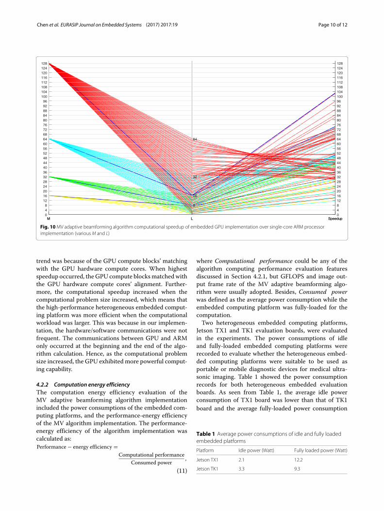
implementation over its ARM processor counterpartwas another important evaluation feature of the MVadaptive beamforming algorithm implementation on thehigh-performance heterogeneous embedded computingplatform. The overall speedup results of the GPU imple-mentation over the single-core ARM processor imple-mentation for variousM and L combinations were shownin Fig. 10. As seen from Fig. 10, the highest speedup inall the conducted experiments was 102.7 times, also in thecase that M was 128, L was 16, and the GPU computethread block size was 32. The dark blue lines in Fig. 10represented the highest speedup cases for the specificvalues of M. For other specific values of M, the high-est speedup for M = 64 was 74.4 times when L = 16,the highest speedup for M = 32 was 50.1 times whenL = 8, and the highest speedup for M = 16 was31.0 times when L = 7. Therefore, as seen from theresults, asM decreased, the fraction of L overM increasedwhen the highest speedup was achieved for specificM. Inour experiments, L/M increased from 1/8 to nearly 1/2when M decreased from 128 to 16. The reason of this
Chen et al. EURASIP Journal on Embedded Systems (2017) 2017:19 Page 10 of 12
M L Speedup048
12162024283236404448525660646872768084889296
100104108112116120124128
8
16
32
64
M L Speedup04812162024283236404448525660646872768084889296100104108112116120124128
Fig. 10MV adaptive beamforming algorithm computational speedup of embedded GPU implementation over single-core ARM processorimplementation (variousM and L)
trend was because of the GPU compute blocks’ matchingwith the GPU hardware compute cores. When highestspeedup occurred, the GPU compute blocksmatchedwiththe GPU hardware compute cores’ alignment. Further-more, the computational speedup increased when thecomputational problem size increased, which means thatthe high-performance heterogeneous embedded comput-ing platform was more efficient when the computationalworkload was larger. This was because in our implemen-tation, the hardware/software communications were notfrequent. The communications between GPU and ARMonly occurred at the beginning and the end of the algo-rithm calculation. Hence, as the computational problemsize increased, the GPU exhibited more powerful comput-ing capability.
4.2.2 Computation energy efficiencyThe computation energy efficiency evaluation of theMV adaptive beamforming algorithm implementationincluded the power consumptions of the embedded com-puting platforms, and the performance-energy efficiencyof the MV algorithm implementation. The performance-energy efficiency of the algorithm implementation wascalculated as:Performance − energy efficiency =
Computational performanceConsumed power
,
(11)
where Computational performance could be any of thealgorithm computing performance evaluation featuresdiscussed in Section 4.2.1, but GFLOPS and image out-put frame rate of the MV adaptive beamforming algo-rithm were usually adopted. Besides, Consumed powerwas defined as the average power consumption while theembedded computing platform was fully-loaded for thecomputation.Two heterogeneous embedded computing platforms,
Jetson TX1 and TK1 evaluation boards, were evaluatedin the experiments. The power consumptions of idleand fully-loaded embedded computing platforms wererecorded to evaluate whether the heterogeneous embed-ded computing platforms were suitable to be used asportable or mobile diagnostic devices for medical ultra-sonic imaging. Table 1 showed the power consumptionrecords for both heterogeneous embedded evaluationboards. As seen from Table 1, the average idle powerconsumption of TX1 board was lower than that of TK1board and the average fully-loaded power consumption
Table 1 Average power consumptions of idle and fully loadedembedded platforms
Platform Idle power (Watt) Fully loaded power (Watt)
Jetson TX1 2.1 12.2
Jetson TK1 3.3 9.3
Chen et al. EURASIP Journal on Embedded Systems (2017) 2017:19 Page 11 of 12
of TX1 board was higher than that of TK1 board, whichdemonstrated the dynamic power saving scheme of TX1development board. The power consumption measure-ments demonstrated that the heterogeneous embeddedGPU platforms can be used in the portable or mobilediagnostic device constructions.Referring to (11) and the results discussed in
Section 4.2.1, the highest performance-energy efficiencyof Jetson TX1 heterogeneous embedded comput-ing platform could be calculated as 88.98/12.2 =7.29 GFLOPS/Watt or 58.82/12.2 = 4.80 fps/Watt.Besides, the highest operation calculation throughput ofthe MV adaptive beamforming algorithm on Jetson TK1heterogeneous embedded computing platform was 37.52GFLOPS in the case that M was 128, L was 32, and theGPU compute thread block size was 128, and the highestoutput image frame rate of the MV adaptive beamform-ing algorithm on Jetson TK1 heterogeneous embeddedcomputing platform was 17.24 fps in the case that M was16, L was 1, and the GPU compute thread block size was64. As a result, the highest performance-energy efficiencyof Jetson TK1 heterogeneous embedded computing plat-form was calculated as 37.52/9.3 = 4.03 GFLOPS/Watt or17.24/9.3 = 1.85 fps/Watt. Therefore, the performance-energy efficiency results of the two heterogeneousembedded computing platform demonstrated that theembedded computing platform consumed more powerdid not mean that it had a lower performance-energyefficiency. In the experiments, the TX1 embedded com-puting platform with higher average fully-loaded powerconsumption exhibited higher performance-energyefficiency.
4.2.3 Platform cost efficiencyOne of the important evaluation aspect of the embed-ded MV adaptive beamforming algorithm implementa-tion was the cost of the implementation platform and itscost efficiency. The cost efficiency was calculated as:
Platform cost efficiency =Computational performance
Platform cost,
(12)
where Computational performance could be GFLOPSthroughput or image output frame rate of theMV adaptivebeamforming algorithm. Furthermore, the cost of the het-erogeneous embedded computing platform Platform costwas measured in US dollars.As stated in the official website of Nvidia Corpora-
tion, Jetson TX1 heterogeneous embedded computingplatform cost $600 and Jetson TK1 heterogeneous embed-ded computing platform cost $200. When considering
the highest computational performance of the hetero-geneous embedded computing platforms, the highestcost efficiency of the Jetson TX1 heterogeneous embed-ded computing platform was expressed as 88.98/600 =0.148 GFLOPS/dollar or 58.82/600 = 0.098 fps/dollar.Similarly, the highest cost efficiency of the Jetson TK1 het-erogeneous embedded computing platformwas expressedas 37.52/200 = 0.188 GFLOPS/dollar or 17.24/200 =0.086 fps/dollar. Hence, the Jetson TX1 embedded com-puting platform has lower platform cost efficiency ascompared to Jetson TK1 embedded computing platformin terms of GFLOPS throughput, and slightly higher plat-form cost efficiency as compared to Jetson TK1 embeddedcomputing platform in terms of image output frame rateperformance.If the computation energy efficiency and the platform
cost combined together, the performance-power-cost effi-ciency was obtained, which was calculated as:
Perforamnce − power− cost efficiency
= Performance-energy efficiencyPlatform cost
.
(13)
As a result, the highest performance-power-costefficiency of Jetson TX1 heterogeneous embed-ded computing platform was 7.29/600 = 0.01215GFLOPS/Watt/dollar or 4.80/600 = 0.00800fps/Watt/dollar. Similarly, the highest performance-power-cost efficiency of the Jetson TK1 heterogeneousembedded computing platform was 4.03/200 =0.02015 GFLOPS/Watt/dollar or 1.85/200 = 0.00925fps/Watt/dollar. Therefore, the Jetson TK1 embeddedcomputing platform has higher performance-power-cost efficiency over Jetson TX1 embedded computingplatform in both computing performance measurementmeans.
5 ConclusionsIn this paper, the MV adaptive beamforming algorithmimplementation on heterogeneous high-performanceembedded computing platforms was investigated.According to the effective high-performance GPU imple-mentation strategies, the MV adaptive beamformingalgorithm implementation in high-performance embed-ded GPU on Jetson TX1 platform can fulfil the real-timeimaging requirements for medical ultrasonic imaging inmany test cases, and can achieve 102.7 times speedupover its ARM processor counterpart. Besides, the powerconsumptions of the two experimental heterogeneoushigh-performance embedded platforms illustrated thatthe heterogeneous embedded computing platforms canbe used as portable or mobile medical ultrasonic devices.Furthermore, the computation energy efficiency and
Chen et al. EURASIP Journal on Embedded Systems (2017) 2017:19 Page 12 of 12
platform cost efficiency of the heterogeneous embeddedcomputing platforms demonstrated that the heteroge-neous embedded computing platforms had relativelygood implementation efficiency. As a result, the hetero-geneous embedded computing platforms investigated inthis paper were suitable to construct real-time portable ormobile high-quality medical ultrasonic imaging devices,especially the Jetson TX1 platform.
AcknowledgementsThis work is supported by “Guangdong Natural Science Foundation” (No.2016A030310412), “Guangzhou Science and Technology Program” (KeyLaboratory Project, No. 15180007), and “Guangzhou Science and TechnologyProgram” (No. 201605130108484).
Competing interestsThe authors declare that they have no competing interests.
Received: 29 July 2016 Accepted: 3 January 2017
References1. E Quaia, E Baratella, G Poillucci, AG Gennari, MA Cova, Diagnostic impact
of digital tomosynthesis in oncologic patients with suspected pulmonarylesions on chest radiography. European Radiology. 26(8), 2837–2844(2016)
2. S Tang, Q Du, T Liu, L Tan, M Niu, L Gao, Z Huang, C Fu, T Ma, X Meng, HShao, In vivo magnetic resonance imaging and microwavethermotherapy of cancer using novel chitosan microcapsules. NanoscaleRes. Lett. 11(334), 1–8 (2016)
3. C Love, CJ Palestro, Nuclear medicine imaging of bone infections. Clin.Radiol. 71(7), 632–646 (2016)
4. BK Hoffmeister, MR Smathers, CJ Miller, JA McPherson, CR Thurston, PLSpinolo, S-R Lee, Backscatter-difference measurements of cancellousbone using an ultrasonic imaging system. Ultrason. Imaging. 38(4),285–297 (2016)
5. D Karimi, P Deman, R Ward, N Ford, A sinogram denoising algorithm forlow-dose computed tomography. BMCMed. Imaging. 16(11), 1–14 (2016)
6. JF Havlice, JC Taenzer, Medical ultrasonic imaging: an overview ofprinciples and instrumentation. Proc. IEEE. 67(4), 620–641 (1979)
7. RSC Cobbold, Foundations of biomedical ultrasound. (Oxford UniversityPress, New York, USA, 2007)
8. B Heyde, M Alessandrini, J Hermans, D Barbosa, P Claus, J D’Hooge,Anatomical image registration using volume conservation to assesscardiac deformation from 3D ultrasound recordings. IEEE Trans. Med.Imaging. 35(2), 501–511 (2016)
9. L Zheng, L Gong, F-C Guo, H Chang, G Liu, Application research onthree-dimensional ultrasonic skeletal imaging mode in detecting fetalupper jaw bone. Int. J. Clin. Exp. Med. 8(8), 12219–12225 (2015)
10. A Bar-Zion, M Yin, D Adam, FS Foster, Functional flow patterns and staticblood pooling in tumors revealed by combined contrast-enhancedultrasound and photoacoustic imaging. Cancer Res. 76(15), 4320–4331(2016)
11. J-F Synnevag, A Austeng, S Holm, Benefits of minimum-variancebeamforming in medical ultrasound imaging. IEEE Trans. Ultrason.Ferroelectr. Freq. Control. 56(9), 1868–1879 (2009)
12. Y Li, JA Jensen, Synthetic aperture flow imaging using dual stagebeamforming: simulations and experiments. J. Acoust. Soc. Am. 133(4),2014–2024 (2013)
13. JA Jensen, NB Svendsen, Calculation of pressure fields from arbitrarilyshaped, apodized, and excited ultrasound transducers. IEEE Trans.Ultrason. Ferroelectr. Freq. Control. 39(2), 262–267 (1992)
14. J-F Synnevag, A Austeng, S Holm, Adaptive beamforming applied tomedical ultrasound imaging. IEEE Trans. Ultrason. Ferroelectr. Freq.Control. 54(8), 1606–1613 (2007)
15. A Papoulis, SU Pillai, Probability, random variables, and stochastic processes,4th edn. (McGraw-Hill, Boston, 2002)
16. GH Golub, CF Van Loan,Matrix computations, 3rd edn. (Johns HopkinsUniversity Press, Baltimore, 1996)
17. Nvidia Jetson TX1 developer kit carrier board specification (NvidiaCorporation, Santa Clara, 2016)
18. Nvidia Tegra K1 series processors with Kepler Mobile GPU for embeddedapplications data sheet (Nvidia Corporation, Santa Clara, 2015)
Submit your manuscript to a journal and benefi t from:
7 Convenient online submission
7 Rigorous peer review
7 Immediate publication on acceptance
7 Open access: articles freely available online
7 High visibility within the fi eld
7 Retaining the copyright to your article
Submit your next manuscript at 7 springeropen.com