Embed Size (px)
Citation preview
Research on Resistance Characteristics of Axial Breather with Tangential Air Inlet
Qijun Wang1, a, Rangshu Xu2, b, Zhe Dong2, c and Ning Ge 2, d 1Shenyang Institute of Special Equlpment Inspection & research, Shenyang, China
2Shenyang Aerospace University, Shenyang, China [email protected], [email protected], [email protected],
Keywords: Aero-engine; shaft center breather; numerical simulation; eccentric arm; Abstract. By calculating fluid dynamics (CFD), the flow field of several shaft center breathers in different structure has been researched in detailed. Computational domain is simplified according to the actual requirement. RSM turbulent model is used to simulate the strongly swirling turbulent flow field of the shaft center breather. It is proved that the final results of numerical simulations have certain reliability, which could be used to study the resistance characteristic affected by structure parameters.
This paper also analyzes the shaft center breather velocity fields and total pressure distribution, focus on a case that pressure on import and export along with total pressure loss. By contrast, the increasing eccentric arm brings more pressure loss at the same rotational speed, in other words, the resistance in the shaft center breather gets bigger. In addition, the increase of rotational speed leads to the increase in pressure loss at the same eccentric arm, and the increase of rotational speed gets more significant impact on the shaft center breather with the bigger eccentric arm. The results of the study contribute to an optimized shaft center breather technology.
Introduction Although axial ventilator began to study in a foreign country in the 1950s, it also faces great
difficulty in experimental study and numerical simulation because of high speed rotating engine working conditions and the complexity of the two-phase flow problem and ventilator internal complex flow channel (vortex, impact, turn-back) flows. Therefore, in the open literature, reports of aeroengine ventilator research are very few, especially about its internal analysis of the flow resistance, at present, there is no theoretical calculation formula and empirical formula for the use of the design.
Hua Zhou and Nan Xia[1] carried on a numerical simulations on the flow field of gas-liquid two phase flow in oil and gas separator. Analysis the result of the calculation found that, in addition to the centrifugal force effect can improve separation efficiency, air flow on the wall of the collision process also plays an important role to improve the effect of separation.
Defu Chen[2] also summarized the commonly used separation mechanism of the particle, it was concluded that the oil and gas separation mechanism of axial ventilator was given priority to with inertial force, centrifugal force, and the turbulent dispersion of the conclusion.
K. Willenborg[3] studied sponge metal (metal terms) matrix of aeroengine ventilator by experimental method, using the non-invasive optical measurement technology separation efficiency analysis and optimization of parameter determination. The diffraction method is used to measure the size distribution of the ventilator into the oil droplet; Ventilator exports of droplets size distribution and volume concentration based on Mie theory (Mie going) wavelength of extinction method of scattering Quotient (Dispersion - Quotient, DQ) measurement technology. Under the condition of different air flow, oil flow rate, rotational speed and oil droplets size to carry on experiment and measured the separation efficiency and pressure loss, given the above parameters on the separation efficiency and pressure loss of quantitative influence law; In addition, the results showed that only less than a certain size (~ 0.5 microns) of oil droplets by ventilator, and ventilator itself does not produce oil mist in the experiment. In the oil and gas separator for Dunlop company Retimet sponge metal matrix materials.
3rd International Conference on Mechatronics and Information Technology (ICMIT 2016)
© 2016. The authors - Published by Atlantis Press 851
Glahn [4] [5] [6] predict oil system components in the oil and gas two phase flow by CFD method and point out that the Computational Fluid Dynamics (CFD) is the efficacy assessment of axial ventilator and one of the important means of optimization design.
Jianmei Feng[11] carry on a kind of numerical simulation without moving parts in the oil and gas separator of oil droplets trajectories. The oil content of the oil and gas separator in the oil and gas two phase flow are simulated. Under the condition of without considering interphase interactions, the gas phase adopts the RNG k- epsilon turbulence model, oil droplets phase using random trajectory model.
Comprehensive reports in recent years, numerical method is applied to all kinds of research progress of oil and gas separation device, can be determined, axial ventilator by numerical method analysis and study of oil and gas separation process is feasible.
This article based on the understanding of the mechanism of oil and gas separation on the ventilator, using numerical calculation method, by changing the position of ventilator shaft, the paper analyses the characteristics of the fluid flow resistance inside the ventilator, the tangential pore structure characteristics of the ventilator, in order to provide certain reference to optimize the design of axial ventilator structure in the future.
Research Design
Analysis. The axis ventilators communicating oil chamber, front bearing chamber, rear bearing chamber and accessory drive casing. Bearing cavity separated air flow path or gas flow paths by sealing means. Seal leak, oil evaporation, the air heated by flying oil can make the pressure of oil chamber increases. Therefore, inside the aircraft engine it needs proper ventilation, the pressure inlet can maintained within a certain range, to ensure oil system is working properly, the flow resistance characteristics which played a key role in the axial ventilation.
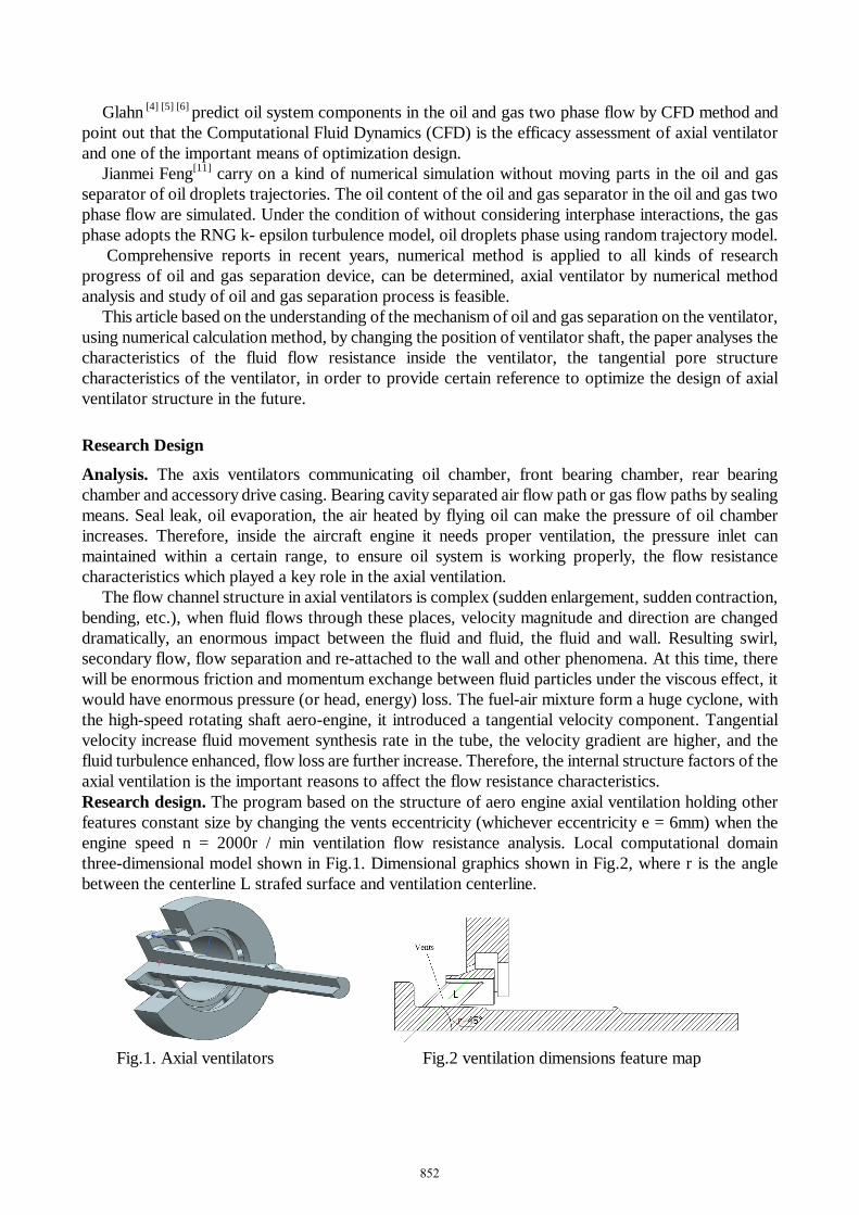
The flow channel structure in axial ventilators is complex (sudden enlargement, sudden contraction, bending, etc.), when fluid flows through these places, velocity magnitude and direction are changed dramatically, an enormous impact between the fluid and fluid, the fluid and wall. Resulting swirl, secondary flow, flow separation and re-attached to the wall and other phenomena. At this time, there will be enormous friction and momentum exchange between fluid particles under the viscous effect, it would have enormous pressure (or head, energy) loss. The fuel-air mixture form a huge cyclone, with the high-speed rotating shaft aero-engine, it introduced a tangential velocity component. Tangential velocity increase fluid movement synthesis rate in the tube, the velocity gradient are higher, and the fluid turbulence enhanced, flow loss are further increase. Therefore, the internal structure factors of the axial ventilation is the important reasons to affect the flow resistance characteristics. Research design. The program based on the structure of aero engine axial ventilation holding other features constant size by changing the vents eccentricity (whichever eccentricity e = 6mm) when the engine speed n = 2000r / min ventilation flow resistance analysis. Local computational domain three-dimensional model shown in Fig.1. Dimensional graphics shown in Fig.2, where r is the angle between the centerline L strafed surface and ventilation centerline.
Fig.1. Axial ventilators Fig.2 ventilation dimensions feature map
852
Control Equation and Calculation Model Oil and gas two-phase flow process is very complex axial ventilation inside, the oil particles are in a
fog shape with air movement, the volume fraction is less than 10%, which is a dilute phase two phase flow, the interaction between particles is weak and can be neglected, so it can be regarded as a continuous medium fluid. Axial ventilators in the presence of a strong cyclone, strong turbulence flow field, In order to consider more stringent curved flow line, swirl, rotation, and rapid changes in the tension, we Reynolds stress model (RSM) to complex flows, higher forecast accuracy. Turbulence model. With the high-speed rotating shaft engine air two-phase flow in the axial ventilator, Oil and gas mixture form a huge vortex, The fundamental difference between the cyclone and the cyclone is not rotating Axial introduced tangential velocity component, The fundamental difference between the cyclone and the cyclone is not rotating Axial introduced tangential velocity component. Tangential velocity such that the fluid movement of the inner tube synthesis rate increased, with greater velocity gradient, the fluid of the inner tube to form strong turbulence, so the use of the turbulence model.
When the relevant information of the stress tensor is short, the Reynolds averaged N-S equations and their simplified form cannot be solved because the equations are not closed, the same problem also appears in the energy equation.
In addition to well-known area next to the wall, the turbulent flow item is typically much greater diffusion layer diffusion. In the wall turbulent boundary layer flow, wake, jet and more complex flow, turbulent diffusion terms correspond to the magnitude of the convective terms. In order to solve the problem of turbulence closure model, there are several models of turbulence. For the near wall boundary layer flow and the jet, the early turbulent model based on the Prandtl mixing length hypothesis and the Boussinesq eddy viscosity assumption.
Mixed length l is defined as 2 2- 'v' ( )l
yµ
ρµ ρ∂
=∂
(1)
The expression of eddy viscosity coefficient mε is:
( ) 2m tri
uly
ε γ∂
=∂
(2)
A large number of turbulent models have been developed based on these two assumptions, and they have been widely used in the prediction of a variety of flows so far.
Currently many types of two-equation model, the following few most widely used mode. k ε− Mode, and turbulent kinetic energy k dissipation rate transport equationε were:
jm i im
j i j
uu uDDt x x x x xκ κ κ
εκ κν ε ε
σ
∂ ∂ ∂∂ ∂= + + + − ∂ ∂ ∂ ∂ ∂
(3)
1 2
2jm i i
j i j
uu uD c cDt x x x x xε ε
κ ε κ
εε ε ε εν
σ κ κ
∂ ∂ ∂∂ ∂= + + + − ∂ ∂ ∂ ∂ ∂
(4)
At high Reynolds numbers, the Eq.3 and equation Eq.4 are transformed into the boundary layer flow.
2
mm
uu vx y y y yκ
εκ κ κε ε
σ ∂ ∂ ∂ ∂ ∂
+ = + − ∂ ∂ ∂ ∂ ∂ (5)
1 2
2 2m
muu v c c
x y y y yε εε
εε ε ε ε εε
σ κ κ ∂ ∂ ∂ ∂ ∂
+ = + − ∂ ∂ ∂ ∂ ∂ (6)
Each mode constant: 1 2
0.09, 1.44, 1.92, 1.0, 1.3c c cµ ε ε κ εσ σ= = = = = (7)
853
The above Eq. 3 ~ 6 is only suitable for free shear flow, and it needs to be modified according to the characteristics of the near wall of the flow when it is applied to the wall boundary layer flow.If you do not take into account the wall function, it must be y = 0 at replace the realistic boundary conditions for outside the viscous sublayer at a location Y0 new "boundary conditions", so as to avoid the equation in the near wall method to the large gradient region integration.
There are many methods for the model of the turbulent kinetic energy and its dissipation rate equation in the near wall region. A wall function is introduced into the Eq.5 and Eq.6, so that the model equation can be integrated in the whole boundary layer. In addition, the near wall correction methods, such as Launder and Sharma, are modified to:
2
t c fµ µ
κν
ε=
(8)
The Eq.5 and Eq.6 are: 212 2
2tt
uu vx y y y y yκ
νκ κ κ κν ε ν
σ
∂ ∂ ∂ ∂ ∂ ∂ + = + − − ∂ ∂ ∂ ∂ ∂ ∂ (9)
1 2
2 2 2
2 22tt t
u uu v c f cx y y y y yε ε
ε
νε ε ε ε εν νν
σ κ κ ∂ ∂ ∂ ∂ ∂ ∂
+ = + − + ∂ ∂ ∂ ∂ ∂ ∂ (10)
among them:
( )2
23.4exp ,
1 50t
t
e
e
f RR
µκνε
= − = +
(11)
( )22 1 0.3exp
tef R= − − (12)
( )22 1 0.3exp
tef R= − − (13)
In order to avoid numerical problems, ek and eε ,The value should not be zero. However, their value can not be arbitrarily given, but by the transport Eq.8 and Eq.9 of the decision, the two equations in the boundary layer into the outer edge:
ee e
dudxκ
ε= − (14)
2
2e e
ee
du cdx εε ε
κ= − (15)
The above equations can be integral to x, and the initial values 0ek and 0eε are respectively 0x . The resulting solutions describe the K (x) and ε (x) the variation of them can be used as boundary conditions for K and transport equations. The numerical simulation of turbulent flow can be divided into three types, Direct Numerical Simulation, DNS, Large Eddy Simulation, LES, Simulation method of Reynolds equation for general use in current engineering flow calculation. For engineering applicability and computational resource constraints, we can only use the Reynolds equation modeling method.
Axial ventilator in the flow field is very complex, for there is a strong streamline curvature, swirling and swirling flow field, realizable model and the RNG model has better performance. But because the above two kinds of turbulence models are not suitable to solve the problem of the existence of the two flow field. RSM (Reynolds Stress Model) model is the most sophisticated production, Reynolds stress equation method to solve the Reynolds stress ( i ju uρ ′ ′− ) transport equation and dissipation rate transport equation makes Reynolds average Navier-Stokes equations closed, and give an isotropic eddy viscosity is assumed. RSM on complex flow with higher accuracy in prediction of potential, for this paper research with a strong cyclone and strong turbulence flow field of axial ventilator for, more stringent considered streamline bending, whirlpool, rotation and the tension of the change. However,
854
the simulation of the Reynolds stress transport equation is used to make the model of the RMS equation have some limitations, especially the simulation of the stress - strain redistribution and dissipation term is the main problem. Reynolds stress model. The strict form of the Reynolds stress transport equation can be derived by the strict form of the momentum equation. The Navier Stokes equations in the instantaneous value of said too mean and fluctuating value and, and from subtracting the Reynolds averaged equations, equations of velocity fluctuation, and then multiplied by the velocity fluctuation after retaking the mean, the Reynolds stress transport equation:
( ) ( ) ( )( ) ( ), ,
Local time derivative term convertion turbulent diffusion molecular diffusionij T ij L ij
i j k i j i j k kj i ik j i jk k k k
C D D
u u u u u u u u p u u u ut x x x x
ρ ρ ρ δ δ µ
≡ ≡ ≡
∂ ∂ ∂ ∂ ∂′ ′ ′ ′ ′ ′ ′ ′ ′ ′ ′ ′+ = − + + + ∂ ∂ ∂ ∂ ∂ 14243 1442443 1444442444443 144424443
( )
buoyancy productionstress production pressure strain
dissiption
2
ijij ij
ij
j ji ii k j k i j j i
k k j iG
P
ji
k k
u uu uu u u u g u g u px x x x
uux x
φ
ε
ρ ρβ θ θ
µ
≡≡ ≡
≡
′∂ ∂ ′∂ ∂′ ′ ′ ′ ′ ′ ′− + − + + + ∂ ∂ ∂ ∂
′∂′∂− −
∂ ∂
14442444314444244443 1442443
14243( )
user-difined source termproduction by system rotation
2
ij
j m ikm i m jkm user
F
u u u u Sρ ε ε
≡
′ ′ ′ ′Ω + +14444244443
(16)
In the formula, ρ is the density, u is the time average velocity, u′ is the pulse velocity, µ is the viscosity, β is the volume expansion coefficient, g is the gravity acceleration, Ω is the average transfer rate tensor. Near wall treatment. This model, adopts wall function method, does not solve the viscous flow in the bottom layer and the transition layer, and the semi empirical formula is used to relate the wall surface to the turbulent zone. Two wall functions are provided in fluent: the standard wall function and the non-equilibrium wall function.
The standard wall function can reasonably predict the flow near wall of most high Reynolds number. The non-equilibrium wall function is mainly applied to the condition that the pressure gradient of the near wall is large or the degree of imbalance is very high. The variable axial ventilator internal wall flow field without a large pressure gradient and other highly imbalanced, the situation is basically in line with the conditions for the use of the standard wall function.
The Numerical Calculation of the Axial Ventilator This paper mainly uses the CFD(Computational Fluid Dynamics) method to simulate the inner flow.
The model have six radial holes and six radials in low-pressure rotor shaft and axial ventilator uniformly distributed in a circumferential direction. Thus, the axis ventilation flow channel structure having a 60° rotation cycle periodically. However ventilator tester has only one radial inlet tube, seemingly the flow state within the ventilation is not cyclical, but because of the ventilation test space is large enough, with the low-pressure rotor shaft rotary motion, before the fuel-air mixture fluid in the rotor axis radial holes has been distributed in the circumferential direction. Therefore, the flow in the rotor shaft radial flow bore and annular chamber and the axis ventilation is approximate rotationally periodic flow. So the computation domain is only required to take its 1/6 sector. Compared with the computational domain contains the entire test area, the computational domain can make computing more effective control and solving faster, it is advantageous to get the result of the calculation in the comparison study of the variable parameter.
855
Analysis of calculation results Axial ventilator design indexes should meet two aspects: axial ventilator, oil and gas separation
efficiency must be as high as possible and has certain stability, to meet the ventilator in various conditions were higher in the oil and gas separation performance, another important indicator is the flow resistance, it is one of the key factors that affect the transmission of the cavity pressure. Resistance is too large, it will seriously affect the ventilation capacity, resulting in increased pressure on the engine transmission chamber; resistance is too small and will make the transmission chamber pressure is too low, resulting in the sealing device before and after the pressure difference increased, the amount of air leakage increased. The calculation results are analyzed in this chapter. The numerical results of the analysis help to understand the structure of ventilator to axial ventilator flow resistance characteristics influence, for ventilation design and optimization provide theoretical basis. Flow field analysis.Total pressure distribution of the data acquisition and processing using numerical method for axial ventilation flow field of different structural parameters of the numerical simulation model to be flowing into a stable condition, to give axial ventilation inlet and outlet sections, speed distribution.
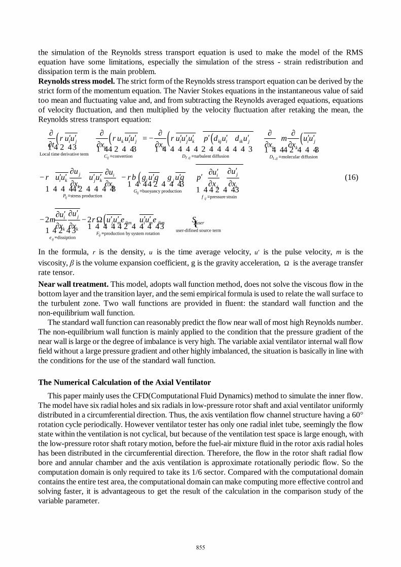
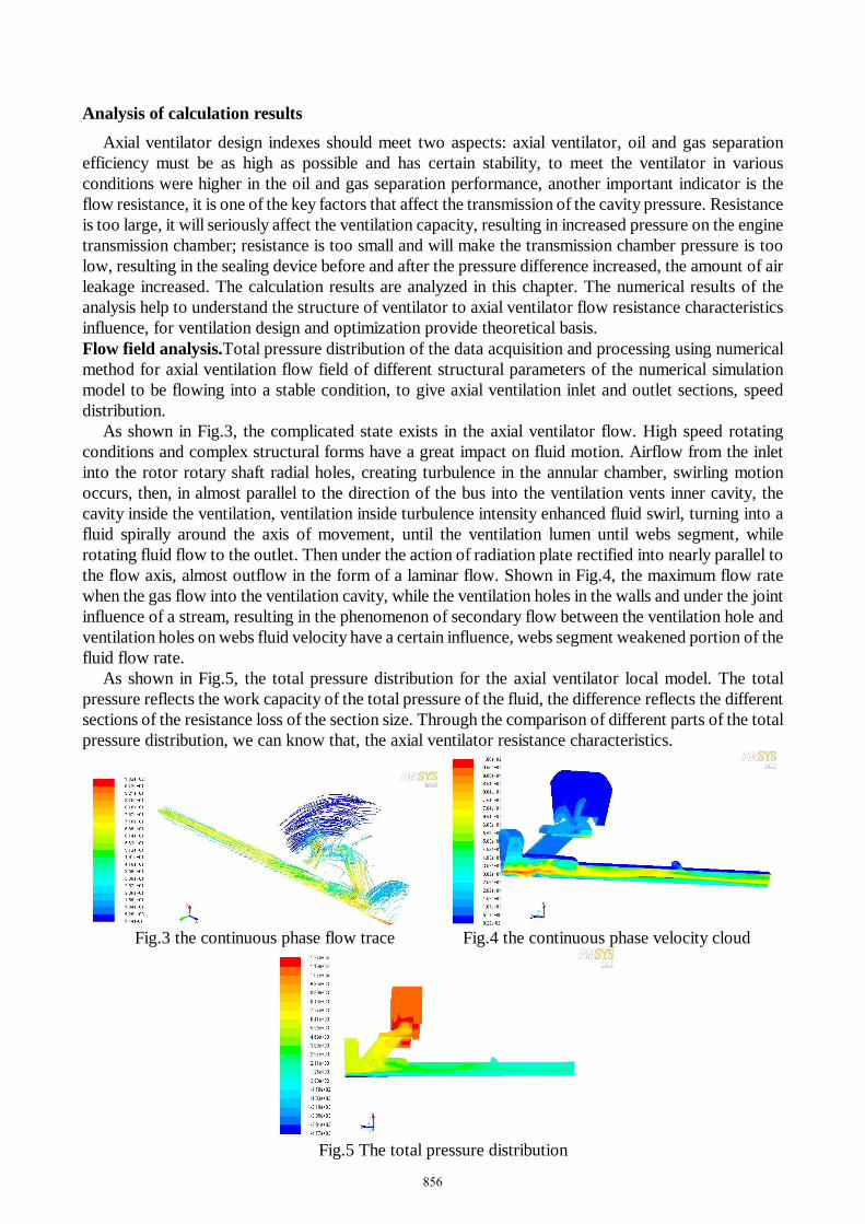
As shown in Fig.3, the complicated state exists in the axial ventilator flow. High speed rotating conditions and complex structural forms have a great impact on fluid motion. Airflow from the inlet into the rotor rotary shaft radial holes, creating turbulence in the annular chamber, swirling motion occurs, then, in almost parallel to the direction of the bus into the ventilation vents inner cavity, the cavity inside the ventilation, ventilation inside turbulence intensity enhanced fluid swirl, turning into a fluid spirally around the axis of movement, until the ventilation lumen until webs segment, while rotating fluid flow to the outlet. Then under the action of radiation plate rectified into nearly parallel to the flow axis, almost outflow in the form of a laminar flow. Shown in Fig.4, the maximum flow rate when the gas flow into the ventilation cavity, while the ventilation holes in the walls and under the joint influence of a stream, resulting in the phenomenon of secondary flow between the ventilation hole and ventilation holes on webs fluid velocity have a certain influence, webs segment weakened portion of the fluid flow rate.
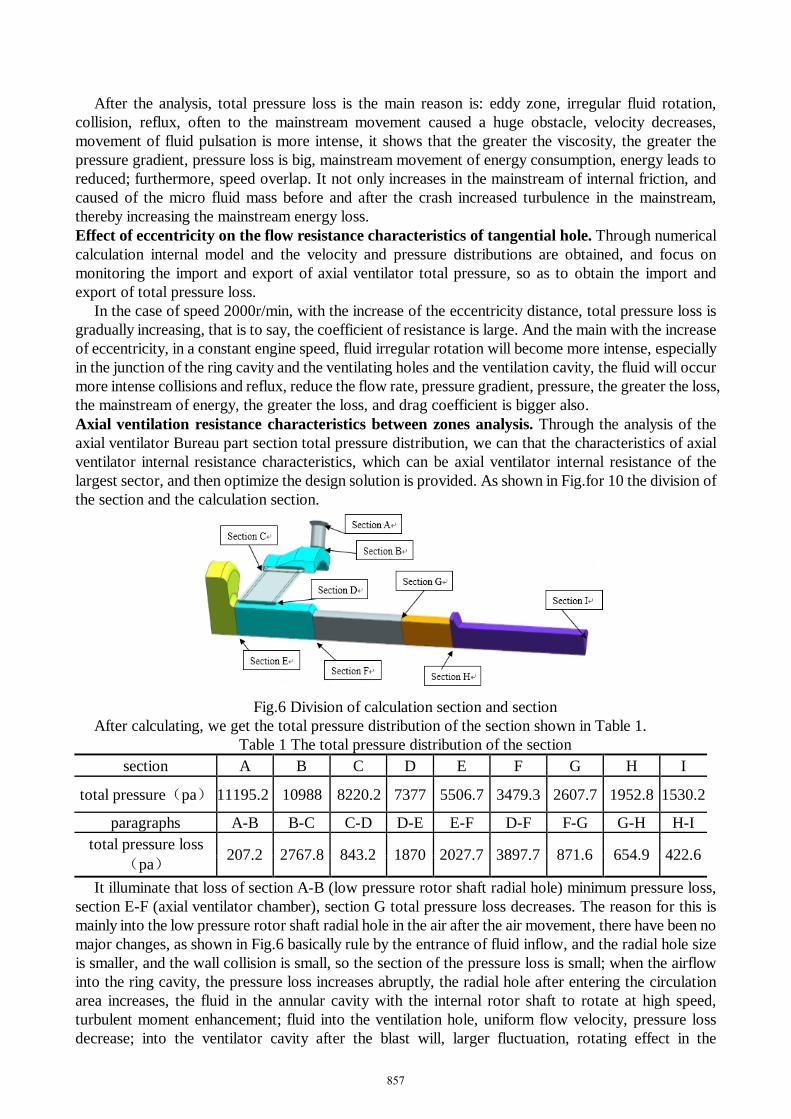
As shown in Fig.5, the total pressure distribution for the axial ventilator local model. The total pressure reflects the work capacity of the total pressure of the fluid, the difference reflects the different sections of the resistance loss of the section size. Through the comparison of different parts of the total pressure distribution, we can know that, the axial ventilator resistance characteristics.
Fig.3 the continuous phase flow trace Fig.4 the continuous phase velocity cloud
Fig.5 The total pressure distribution
856
After the analysis, total pressure loss is the main reason is: eddy zone, irregular fluid rotation, collision, reflux, often to the mainstream movement caused a huge obstacle, velocity decreases, movement of fluid pulsation is more intense, it shows that the greater the viscosity, the greater the pressure gradient, pressure loss is big, mainstream movement of energy consumption, energy leads to reduced; furthermore, speed overlap. It not only increases in the mainstream of internal friction, and caused of the micro fluid mass before and after the crash increased turbulence in the mainstream, thereby increasing the mainstream energy loss. Effect of eccentricity on the flow resistance characteristics of tangential hole. Through numerical calculation internal model and the velocity and pressure distributions are obtained, and focus on monitoring the import and export of axial ventilator total pressure, so as to obtain the import and export of total pressure loss.
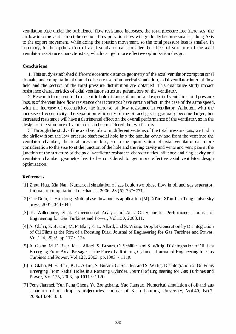
In the case of speed 2000r/min, with the increase of the eccentricity distance, total pressure loss is gradually increasing, that is to say, the coefficient of resistance is large. And the main with the increase of eccentricity, in a constant engine speed, fluid irregular rotation will become more intense, especially in the junction of the ring cavity and the ventilating holes and the ventilation cavity, the fluid will occur more intense collisions and reflux, reduce the flow rate, pressure gradient, pressure, the greater the loss, the mainstream of energy, the greater the loss, and drag coefficient is bigger also. Axial ventilation resistance characteristics between zones analysis. Through the analysis of the axial ventilator Bureau part section total pressure distribution, we can that the characteristics of axial ventilator internal resistance characteristics, which can be axial ventilator internal resistance of the largest sector, and then optimize the design solution is provided. As shown in Fig.for 10 the division of the section and the calculation section.
Fig.6 Division of calculation section and section
After calculating, we get the total pressure distribution of the section shown in Table 1. Table 1 The total pressure distribution of the section
section A B C D E F G H I
total pressure(pa) 11195.2 10988 8220.2 7377 5506.7 3479.3 2607.7 1952.8 1530.2
paragraphs A-B B-C C-D D-E E-F D-F F-G G-H H-I total pressure loss
(pa) 207.2 2767.8 843.2 1870 2027.7 3897.7 871.6 654.9 422.6
It illuminate that loss of section A-B (low pressure rotor shaft radial hole) minimum pressure loss, section E-F (axial ventilator chamber), section G total pressure loss decreases. The reason for this is mainly into the low pressure rotor shaft radial hole in the air after the air movement, there have been no major changes, as shown in Fig.6 basically rule by the entrance of fluid inflow, and the radial hole size is smaller, and the wall collision is small, so the section of the pressure loss is small; when the airflow into the ring cavity, the pressure loss increases abruptly, the radial hole after entering the circulation area increases, the fluid in the annular cavity with the internal rotor shaft to rotate at high speed, turbulent moment enhancement; fluid into the ventilation hole, uniform flow velocity, pressure loss decrease; into the ventilator cavity after the blast will, larger fluctuation, rotating effect in the
857
ventilation pipe under the turbulence, flow resistance increases, the total pressure loss increases; the airflow into the ventilation tube section, flow pulsation flow will gradually become smaller, along Axis to the export movement, while doing the rotation movement, so the total pressure loss is smaller. In summary, in the optimization of axial ventilator can consider the effect of structure of the axial ventilator resistance characteristics, which can get more effective optimization design.
Conclusions 1. This study established different eccentric distance geometry of the axial ventilator computational
domain, and computational domain discrete use of numerical simulation, axial ventilator internal flow field and the section of the total pressure distribution are obtained. This qualitative study impact resistance characteristics of axial ventilator structure parameters on the ventilator.
2. Research found cut to the eccentric hole distance of import and export of ventilator total pressure loss, is of the ventilator flow resistance characteristics have certain effect. In the case of the same speed, with the increase of eccentricity, the increase of flow resistance in ventilator. Although with the increase of eccentricity, the separation efficiency of the oil and gas in gradually become larger, but increased resistance will have a detrimental effect on the overall performance of the ventilator, so in the design of the structure of ventilator can be considered the two factors.
3. Through the study of the axial ventilator in different sections of the total pressure loss, we find in the airflow from the low pressure shaft radial hole into the annular cavity and from the vent into the ventilator chamber, the total pressure loss, so in the optimization of axial ventilator can more consideration to the size to at the junction of the hole and the ring cavity and vents and vent pipe at the junction of the structure of the axial ventilator resistance characteristics influence and ring cavity and ventilator chamber geometry has to be considered to get more effective axial ventilator design optimization.
References
[1] Zhou Hua, Xia Nan. Numerical simulation of gas liquid two phase flow in oil and gas separator. Journal of computational mechanics,.2006, 23 (6), 767~771.
[2] Che Defu, Li Huixiong. Multi phase flow and its application [M]. Xi'an: Xi'an Jiao Tong University press, 2007: 344~345
[3] K. Willenborg, et al. Experimental Analysis of Air / Oil Separator Performance. Journal of Engineering for Gas Turbines and Power, Vol.130, 2008.11.
[4] A. Glahn, S. Busam, M. F. Blair, K. L. Allard, and S. Wittig. Droplet Generation by Disintegration of Oil Films at the Rim of a Rotating Disk. Journal of Engineering for Gas Turbines and Power, Vol.124, 2002, pp.117 ~ 124.
[5] A. Glahn, M. F. Blair, K. L. Allard, S. Busam, O. Schäfer, and S. Wittig. Disintegration of Oil Jets Emerging From Axial Passages at the Face of a Rotating Cylinder. Journal of Engineering for Gas Turbines and Power, Vol.125, 2003, pp.1003 ~ 1110.
[6] A. Glahn, M. F. Blair, K. L. Allard, S. Busam, O. Schäfer, and S. Wittig. Disintegration of Oil Films Emerging From Radial Holes in a Rotating Cylinder. Journal of Engineering for Gas Turbines and Power, Vol.125, 2003, pp.1011 ~ 1120.
[7] Feng Jianmei, Yun Feng Cheng Yu Zongchang, Yao Jianguo. Numerical simulation of oil and gas separator of oil droplets trajectories. Journal of Xi'an Jiaotong University, Vol.40, No.7, 2006.1329-1333.
858