Embed Size (px)
Citation preview

Journal of
Marine Science and Engineering
Article
Research on Optimization and Verification of the Number ofStator Blades of kW Ammonia Working Medium Radial FlowTurbine in Ocean Thermal Energy Conversion
Yun Chen 1,2 , Yanjun Liu 1,2,*, Wei Yang 1, Yiming Wang 2, Li Zhang 3 and Yongpeng Wu 3
Citation: Chen, Y.; Liu, Y.; Yang, W.;
Wang, Y.; Zhang, L.; Wu, Y. Research
on Optimization and Verification of
the Number of Stator Blades of kW
Ammonia Working Medium Radial
Flow Turbine in Ocean Thermal
Energy Conversion. J. Mar. Sci. Eng.
2021, 9, 901. https://doi.org/
10.3390/jmse9080901
Academic Editor:
Constantine Michailides
Received: 5 August 2021
Accepted: 19 August 2021
Published: 20 August 2021
Publisher’s Note: MDPI stays neutral
with regard to jurisdictional claims in
published maps and institutional affil-
iations.
Copyright: © 2021 by the authors.
Licensee MDPI, Basel, Switzerland.
This article is an open access article
distributed under the terms and
conditions of the Creative Commons
Attribution (CC BY) license (https://
creativecommons.org/licenses/by/
4.0/).
1 Institute of Marine Science and Technology, School of Mechanical Engineering, Shandong University,Qingdao 266237, China; [email protected] (Y.C.); [email protected] (W.Y.)
2 Key Laboratory of “High Efficiency Clean Advanced Manufacturing” Ministry of Education,Shandong University, Jinan 250061, China; [email protected]
3 Southern Marine Science and Engineering Guangdong Laboratory, Zhanjiang 524000, China;[email protected] (L.Z.); [email protected] (Y.W.)
* Correspondence: [email protected]; Tel.: +86-133-2513-6508
Abstract: Ocean Thermal Energy Conversion (OTEC) is one of the emerging industries of oceanenergy and an important link in carbon neutrality. Turbine is a key component of ocean thermalenergy conversion, which has an important impact on the performance and energy conversionefficiency of the system. This paper fully considers the application characteristics of ocean thermalenergy conversion and the state conversion characteristics of ammonia working fluid. Taking the100 kW radial inflow turbine in the OTEC application system as an example, based on the design,the turbine is optimized for the key parameters of the turbine stator and the influence of differentgeometric parameters is analyzed. Subsequently, the optimization results are verified by CFDnumerical simulation analysis under different conditions. The results show that the number of statorblades has an important influence on the performance of the turbine. Further optimization studieshave shown that through optimization, when the number of stator blades is 33, the internal flowfield performance is the best, and the working conditions of the inlet and outlet working fluids are inaccordance with the design points without obvious shock wave and reverse flow phenomenon, theefficiency is 89.46%, 3.94% higher than the design value.
Keywords: OTEC; radial inflow turbine; the number of the stator; efficiency
1. Introduction
In a modern society with rapid economic and social development, understandinghow to establish a balance between energy and the environment is an old topic. Thedevelopment and utilization of marine renewable energy is a potential solution to thisproblem [1–5]. On the issue of recent climate change, the attention of ocean energy hasincreased to a higher level [6–9]. Ocean thermal energy conversion [10] is a new typeof renewable energy and an important link in carbon neutrality. For example, if coal issolidified solar energy, then ocean thermal energy conversion is liquefied solar energy.Ocean thermal energy conversion [11] (OTEC) refers to the use of surface warm seawaterto heat certain low-boiling point working fluids and vaporize them to drive steam turbinesto generate electricity; at the same time, deep-layer cold seawater is used to condense theexhausted steam after work into liquid, forming System circulation. The temperature ofseawater below 800 m is constant at about 4 C, thus, the resource distribution of oceantemperature difference energy mainly depends on the surface temperature of the seawater.The lower the latitude, the higher the surface seawater temperature, the more abundantocean thermal energy is stored. Theoretically speaking, the temperature difference energyresources can be developed and utilized in sea areas with a water depth of more than800 m and a temperature difference of more than 18 C. Therefore, among all kinds of
J. Mar. Sci. Eng. 2021, 9, 901. https://doi.org/10.3390/jmse9080901 https://www.mdpi.com/journal/jmse

J. Mar. Sci. Eng. 2021, 9, 901 2 of 15
marine energy, its resource reserves are very large. Different from coal, it is a new energytechnology that is developed and applied, environmentally friendly, pollution-free, andinexhaustible [12,13]. Rankine cycle [14,15] is the most basic cycle of ocean thermal energyconversion, and the national ocean cycle [16] is currently the most efficient. In the cycle, theturbine is used to convert the internal energy of the working fluid into rotating mechanicalenergy and finally into electrical energy, the performance of which plays a decisive role inthe output power and energy conversion efficiency of the entire power generation system.In various forms of turbines, the radial inflow turbine has fewer components, and theoverall structure is simple and compact. In the case of reasonable design, the efficiency ishigher. It can be used under the conditions of small flow, low pressure and low temperature.Achieve higher turbine efficiency.
Although turbines specially used for ocean thermal energy conversion have beenapplied in many thermoelectric energy systems abroad, there are not too many related doc-uments to introduce and elaborate, and there are very few aspects of ocean thermal energyconversion radial inflow turbine stator optimization. In the ORC turbine optimization,Li Xiao [17] took the stator efficiency as the optimization goal, controlled the four angleparameters of the stator profile as design variables, and performed the response surface forthe stator profile of the radial inflow turbine with organic working fluid. After analysisand optimization, the stator efficiency increased by 2% after optimization. Yonghui Xieet al. [18] took the maximum stress minimum as the optimization goal, and selected fourparameters: the middle thickness of the blade hub, the middle thickness of the blade inletend, the absolute airflow angle (the angle with the radial direction), and the relative airflowangle of the blade outlet. The geometry channel has been optimized. Li Yan et al. [19] usedNURBS curves to conduct aerodynamic optimization research on organic working fluidradial inflow turbines, and optimized the stator blade profile and the meridian flow channelof the blade wheel to make the flow channel change more uniform. Tan Xin [20] useda high-precision flow field simulation method for a centrifugal annular cascade turbine.Based on the optimization method, the optimized single-row stator total pressure losscoefficient was reduced by 18.85%, and the wheel circumference efficiency of the entirestage was increased by 4.18%. Wang Xing et al. [21] found that in the stator design process,reducing the thickness of the front and middle sections of the stator can effectively reducethe stator loss coefficient; the change of the profile of the middle section of the blade suctionsurface has a greater impact on the blade loss coefficient, and the pressure surface of theblade. The change of the middle profile has the least influence on the stator loss coefficient.Peng Song et al. [22] took the total efficiency of the turbine as the optimization goal. Thetwo-dimensional stators were parameterized by Bezier splines with 8 control points, andthe rotor channel was generated by Bezier splines with 5 parameters. The runoff turbinehas been aerodynamically optimized. Ayad et al. [23] used the B-spline curve technique todescribe the blade angle and thickness changes, and used 20 design points to optimize thegeometric structure of the stator and rotor blades, and finally determined the best bladeshape of the turbine. Although there are many studies on ocean thermal energy conversion,most of the turbines currently used are directly borrowed from traditional thermoelectricturbines. However, the application requirements for different ocean temperature differ-ences will be different, and the turbines need to be specifically designed and optimized [24].Based on the experimental platform of the First Institute of Oceanography of the Ministry ofNatural Resources and considering the application characteristics of ocean thermal energyconversion and the state conversion characteristics of ammonia working fluid, this papertakes the 100 kW ammonia working fluid radial inflow turbine in the national ocean cycleas the research object, designs the aerodynamic part and completes the CFD aerodynamicperformance simulation analysis. The optimization goal was determined according to thecharacteristics of the internal flow field of the turbine, and the influence of the numberof stator in the standard operating conditions on the turbine performance was furtherdiscussed, the aerodynamic performance of the turbine was optimized, and the expansion

J. Mar. Sci. Eng. 2021, 9, 901 3 of 15
efficiency of the radial turbine was further improved, which provides a technical guaranteefor improving the efficiency of ocean thermal power generation.
2. Materials and Methods2.1. Turbine Aerodynamic Design and 3D Modeling2.1.1. Selection of Pneumatic Parameters
The cycle system proposed by the First Institute of Oceanography, Ministry of NaturalResources [25], is shown in Figure 1. This cycle has the following characteristics: Firstly,the ammonia vaporized from the evaporator first passes through the separator, whichensures the purity of the gas passing through the turbine, and on the other hand, the leanammonia solution from the separator passes through the regenerator 1, and preliminaryheating of the solution from the pump to improve energy utilization. Second, part of theammonia from the separator passes through the turbine to perform work, and the otherpart of the ammonia passes through the regenerator 2 to continue to heat the solutionfrom the regenerator 1. The efficiency of the system is improved by fully applying theabsorbed heat [16].
J. Mar. Sci. Eng. 2021, 9, x FOR PEER REVIEW 3 of 16
field of the turbine, and the influence of the number of stator in the standard operating
conditions on the turbine performance was further discussed, the aerodynamic perfor‐
mance of the turbine was optimized, and the expansion efficiency of the radial turbine
was further improved, which provides a technical guarantee for improving the efficiency
of ocean thermal power generation.
2. Materials and Methods
2.1. Turbine Aerodynamic Design and 3D Modeling
2.1.1. Selection of Pneumatic Parameters
The cycle system proposed by the First Institute of Oceanography, Ministry of Natu‐
ral Resources [25], is shown in Figure 1. This cycle has the following characteristics: Firstly,
the ammonia vaporized from the evaporator first passes through the separator, which
ensures the purity of the gas passing through the turbine, and on the other hand, the lean
ammonia solution from the separator passes through the regenerator 1, and preliminary
heating of the solution from the pump to improve energy utilization. Second, part of the
ammonia from the separator passes through the turbine to perform work, and the other
part of the ammonia passes through the regenerator 2 to continue to heat the solution from
the regenerator 1. The efficiency of the system is improved by fully applying the absorbed
heat [16].
Figure 1. National Sea Cycle.
Based on the National Sea Cycle, the thermal calculation of the overall cycle system
is first performed [26]. The relevant thermal parameters of the turbine inlet and outlet are
obtained, and the results are shown in Table 1.
Table 1. Thermal parameters of the turbine inlet and outlet given by cycle calculation.
Thermal Parameters Results
Inlet total pressure p1/MPa 0.83
Inlet total temperature T1/K 297.15
Outlet static pressure p3/MPa 0.5
Massflow rate 𝑚/kg.s−1 2.44
Isentropic efficiency ηs/‐ 0.85
Figure 1. National Sea Cycle.
Based on the National Sea Cycle, the thermal calculation of the overall cycle system isfirst performed [26]. The relevant thermal parameters of the turbine inlet and outlet areobtained, and the results are shown in Table 1.
Table 1. Thermal parameters of the turbine inlet and outlet given by cycle calculation.
Thermal Parameters Results
Inlet total pressure p1/MPa 0.83Inlet total temperature T1/K 297.15
Outlet static pressure p3/MPa 0.5Massflow rate
.m/kg·s−1 2.44
Isentropic efficiency ηs/- 0.85
2.1.2. Initial Aerodynamic Design and Three-Dimensional Modling
Taking full account of the influence of the thermal properties of the ammonia workingfluid and the environmental peculiarities (small temperature difference) in the actualapplication process of the ocean thermal energy conversion, combined with the design ideasof the ORC radial turbine [27,28], carry out the preliminary startup design and simulationof the turbine optimization. The overall working process and thermal conversion processof the ammonia working fluid radial inflow turbine are similar to the working process andthermal process of the R134 thermal energy conversion radial steam turbine previouslydesigned by our team [29], as shown in Figures 2 and 3. Since the focus of this article is to

J. Mar. Sci. Eng. 2021, 9, 901 4 of 15
introduce the optimization of the ammonia working fluid radial inflow turbine nozzle, theone-dimensional aerodynamic design process will not be expanded in detail.
J. Mar. Sci. Eng. 2021, 9, x FOR PEER REVIEW 4 of 16
2.1.2. Initial Aerodynamic Design and Three‐Dimensional Modling
Taking full account of the influence of the thermal properties of the ammonia work‐
ing fluid and the environmental peculiarities (small temperature difference) in the actual
application process of the ocean thermal energy conversion, combined with the design
ideas of the ORC radial turbine [27,28], carry out the preliminary startup design and sim‐
ulation of the turbine optimization. The overall working process and thermal conversion
process of the ammonia working fluid radial inflow turbine are similar to the working
process and thermal process of the R134 thermal energy conversion radial steam turbine
previously designed by our team [29], as shown in Figures 2 and 3. Since the focus of this
article is to introduce the optimization of the ammonia working fluid radial inflow turbine
nozzle, the one‐dimensional aerodynamic design process will not be expanded in detail.
Figure 2. Schematic of the radial inflow turbine meridional view. Figure 2. Schematic of the radial inflow turbine meridional view.J. Mar. Sci. Eng. 2021, 9, x FOR PEER REVIEW 5 of 16
Figure 3. Turbine thermodynamic process enthalpy and entropy change diagram.
The ammonia working fluid first enters the volute, and the airflow flows evenly to
the stator through the volute; the gas enters the stator for initial expansion, realizing the
conversion of internal energy of gas to kinetic energy (0–1). The gas accelerated in the
stator enters the rotor and the kinetic energy of the gas is transformed into the mechanical
energy of the rotor, and finally converted into electrical energy. On the other hand, the
gas expands further in the moving blades to complete the transformation from internal
energy to mechanical energy (1–2), and the working fluid after work flows out after pass‐
ing through the diffuser. Combining the working process of the turbine, based on the
known design parameters, according to the unary flow theory, under the design condi‐
tions, by referring to the fluid properties of NISTREFPROP 9.0 [30], the thermal parame‐
ters of the ammonia working radial inflow turbine radially are calculated, and the main
design dimensions and structure of the turbine are obtained, which mainly involve the
volute, stator and rotor.
In the actual process of the preliminary design of radial inflow turbine with the am‐
monia working fluid, the selection of empirical parameters takes a lot of time. First, select
the three dimensionless parameters reaction degree Ω, wheel diameter ratio μ, speed ra‐
tio 𝑢, and use genetic algorithm for single‐objective optimization [31] to obtain the design
value corresponding to the maximum turbine efficiency. If the three parameters obtained
are within the parameter range given in the reference, the matching stator speed coeffi‐
cient φ, rotor speed coefficient ψ, rotor inlet absolute airflow angle α1 and outlet relative
airflow angle β2 are further determined; If it is not within the parameter range given in
the reference, adjust the parameter to further optimize. Finally, the optimal 7 basic param‐
eter values under the design conditions are obtained. The specific results and experience
range [32] are shown in Table 2.
Figure 3. Turbine thermodynamic process enthalpy and entropy change diagram.

J. Mar. Sci. Eng. 2021, 9, 901 5 of 15
The ammonia working fluid first enters the volute, and the airflow flows evenly tothe stator through the volute; the gas enters the stator for initial expansion, realizing theconversion of internal energy of gas to kinetic energy (0–1). The gas accelerated in thestator enters the rotor and the kinetic energy of the gas is transformed into the mechanicalenergy of the rotor, and finally converted into electrical energy. On the other hand, thegas expands further in the moving blades to complete the transformation from internalenergy to mechanical energy (1–2), and the working fluid after work flows out after passingthrough the diffuser. Combining the working process of the turbine, based on the knowndesign parameters, according to the unary flow theory, under the design conditions, byreferring to the fluid properties of NISTREFPROP 9.0 [30], the thermal parameters ofthe ammonia working radial inflow turbine radially are calculated, and the main designdimensions and structure of the turbine are obtained, which mainly involve the volute,stator and rotor.
In the actual process of the preliminary design of radial inflow turbine with theammonia working fluid, the selection of empirical parameters takes a lot of time. First,select the three dimensionless parameters reaction degree Ω, wheel diameter ratio µ, speedratio u, and use genetic algorithm for single-objective optimization [31] to obtain thedesign value corresponding to the maximum turbine efficiency. If the three parametersobtained are within the parameter range given in the reference, the matching stator speedcoefficient ϕ, rotor speed coefficient ψ, rotor inlet absolute airflow angle α1 and outletrelative airflow angle β2 are further determined; If it is not within the parameter rangegiven in the reference, adjust the parameter to further optimize. Finally, the optimal7 basic parameter values under the design conditions are obtained. The specific results andexperience range [32] are shown in Table 2.
Table 2. The basic parameters and result.
Empirical Parameters Design Value Experience Value
Ω 0.49 0.35–0.55µ 0.44 0.3–0.5u1 0.623 0.65–0.7ϕ 0.95 0.95–0.97ψ 0.86 0.75–0.85α1/ 16.31 12–30β2/ 33.59 20–45
Specifically, the three dimensionless parameters reaction degree Ω, wheel diameterratio µ, speed ratio u, are defined as follows:
Ω =h2s′
hs, (1)
µ =D2′
D1=
u2m
u1, (2)
u1 =u1
CS, (3)
In addition, h2s′ and hs are the rotor isentropic enthalpy drop and permeability en-thalpy drop, respectively, calculated by Equations (4) and (5), D1, D2′ , u1, u2m are thediameter and circumferential velocity of rotor inlet and outlet, CS is the ideal isentropicspeed, calculated by Equation (6).
h2s′ = i1s − i2s′ , (4)
hs = i0 − i2s , (5)
CS =√
2hs′ , (6)

J. Mar. Sci. Eng. 2021, 9, 901 6 of 15
The results of the initial aerodynamic design are shown in Table 3. It can be seen thatthe designed turbine output is 121.45 kW and the isentropic efficiency is 0.8552, whichmeets the requirements of the turbine design.
Table 3. Initial aerodynamic design results.
Basic Parameter Design Value
Rotor speed N/r·min−1 18,300Power output P/kW 121.45Isentropic expansion efficiency ηs/- 0.8552Height of stator inlet lN/mm 9.38Diameter of stator inlet D0/mm 326Diameter of stator onlet DN/mm 242Rotor inlet absolute airflow angle α1/ 16.31Rotor inlet relative airflow angle β1/ 90.29Rotor inlet circumferential speed u1/m·s−1 244.11Rotor inlet absolute speed c1/m·s−1 253.57Rotor inlet relative speed w1/m·s−1 69.89Rotor inlet diameter D1/mm 240Rotor inlet height l1/mm 11Rotor outlet absolute airflow angle α2/ 87.46Rotor outlet circumferential speed u2/m·s−1 100.53Rotor outlet absolute speed c2/m·s−1 74.87Rotor outlet relative speed w2/m·s-1 129.60Rotor outlet absolute airflow angle β2/ 33.59Rotor outlet outer diameter D2′/mm 128Rotor outlet inner diameter D2”/mm 62Rotor outlet height l2/mm 32Rotor axial length Br/mm 72Diffuser inlet diameter Dk/mm 128Diffuser outlet diameter D3/mm 200Diffuser length L/mm 342
Based on the one-dimensional calculation, the corresponding three-dimensional mod-eling and meshing of the pneumatic components of the turbine are carried out. The voluteis divided into tetrahedral meshes, whose tongue is locally encrypted. The rotor and statorare divided into hexahedral mesh, and the value of y+ near the wall of which is set to 30, andthe O-shaped mesh is used to encrypt it. The overall grid assembled in the CFX pre-processingis shown in Figure 4, and the diffuser is not shown for the convenience of display.
In this article, the commercial numerical analysis software ANSYS CFX V19.0 [33,34]is used to verify the radial inflow turbine designed in the previous section. In the initialstage of the study, the total turbine inlet pressure was set to 0.83 MPa, the total temperaturewas 297.15 K, and the turbine outlet mass flow rate was 2.44 kg/s, which was calculatedby cycles. The rotation speed of the rotor is 18,300 rpm. The relatively moving surface isset as Frozen-rotor, and the relatively static surface is defined as Stage-Frame Change, Inaddition, the “No Sliding Wall” option applies to all walls.
2.2. Optimized Method
The number of stator blades is a key factor affecting the performance of the turbine.The gas from the volute enters the stator to make contact with the stator. A reasonablenumber of stator blades can not only achieve smooth flow distribution, but also enablethe gas to complete ideal expansion in the stator. On the one hand, theoretically, the morestator blades, the smoother the streamlines and the more uniform streamlines entering therotor. However, as the number of stator blades increases, the contact between the gas andthe blade surface will increase, which will increase unnecessary Friction loss. At the sametime, the increase in the number of blades will reduce the flow area, which is equivalent toincreasing a part of the blocking loss. On the other hand, the number of stator blades will

J. Mar. Sci. Eng. 2021, 9, 901 7 of 15
also affect the stator exit speed, and the stator exit speed is the absolute speed of the rotorinlet, which has an important influence on the speed and the airflow angle of the rotor inlet.If the matching is not good, a large flow loss will occur at the stator outlet and the rotorinlet, which will result in a decrease in the output work of the turbine and a decrease in theefficiency of the turbine.
J. Mar. Sci. Eng. 2021, 9, x FOR PEER REVIEW 7 of 16
Rotor outlet circumferential speed u2/m∙s−1 100.53
Rotor outlet absolute speed c2/m∙s−1 74.87
Rotor outlet relative speed w2/m∙s‐1 129.60
Rotor outlet absolute airflow angle β2/° 33.59
Rotor outlet outer diameter D2′/mm 128
Rotor outlet inner diameter D2′’/mm 62
Rotor outlet height 𝑙 /mm 32
Rotor axial length Br/mm 72
Diffuser inlet diameter D /mm 128
Diffuser outlet diameter D /mm 200
Diffuser length L/mm 342
Based on the one‐dimensional calculation, the corresponding three‐dimensional
modeling and meshing of the pneumatic components of the turbine are carried out. The
volute is divided into tetrahedral meshes, whose tongue is locally encrypted. The rotor
and stator are divided into hexahedral mesh, and the value of y+ near the wall of which
is set to 30, and the O‐shaped mesh is used to encrypt it. The overall grid assembled in the
CFX pre‐processing is shown in Figure 4, and the diffuser is not shown for the conven‐
ience of display.
Figure 4. Turbine overall grid diagram.
In this article, the commercial numerical analysis software ANSYS CFX V19.0 [33,34]
is used to verify the radial inflow turbine designed in the previous section. In the initial
stage of the study, the total turbine inlet pressure was set to 0.83 MPa, the total tempera‐
ture was 297.15 K, and the turbine outlet mass flow rate was 2.44 kg/s, which was calcu‐
lated by cycles. The rotation speed of the rotor is 18,300 rpm. The relatively moving sur‐
face is set as Frozen‐rotor, and the relatively static surface is defined as Stage‐Frame
Change, In addition, the “No Sliding Wall” option applies to all walls.
Figure 4. Turbine overall grid diagram.
On the premise that the stator-rotor radial gap remains unchanged, the optimizationmethod is used to optimize the number of blades. By increasing and decreasing the numberof stator blades around the design value, stator blades with different numbers of bladescan be obtained. Firstly, the numerical simulation is carried out by selecting nearby pointswithin the range of ±2 around the design point. After approaching the optimal number,the variation range is reduced to ±1, and the optimal solution is gradually approached. Asshown in the figure, the number of stator blades has increased from 24 to 38, and the anglebetween stator blades has been reduced from γ’ to γ” and γ is the design point value, asshown in Figure 5.
J. Mar. Sci. Eng. 2021, 9, x FOR PEER REVIEW 8 of 16
2.2. Optimized Method
The number of stator blades is a key factor affecting the performance of the turbine.
The gas from the volute enters the stator to make contact with the stator. A reasonable
number of stator blades can not only achieve smooth flow distribution, but also enable the
gas to complete ideal expansion in the stator. On the one hand, theoretically, the more
stator blades, the smoother the streamlines and the more uniform streamlines entering the
rotor. However, as the number of stator blades increases, the contact between the gas and
the blade surface will increase, which will increase unnecessary Friction loss. At the same
time, the increase in the number of blades will reduce the flow area, which is equivalent
to increasing a part of the blocking loss. On the other hand, the number of stator blades
will also affect the stator exit speed, and the stator exit speed is the absolute speed of the
rotor inlet, which has an important influence on the speed and the airflow angle of the
rotor inlet. If the matching is not good, a large flow loss will occur at the stator outlet and
the rotor inlet, which will result in a decrease in the output work of the turbine and a
decrease in the efficiency of the turbine.
On the premise that the stator‐rotor radial gap remains unchanged, the optimization
method is used to optimize the number of blades. By increasing and decreasing the num‐
ber of stator blades around the design value, stator blades with different numbers of
blades can be obtained. Firstly, the numerical simulation is carried out by selecting nearby
points within the range of ±2 around the design point. After approaching the optimal
number, the variation range is reduced to ±1, and the optimal solution is gradually ap‐
proached. As shown in the figure, the number of stator blades has increased from 24 to
38, and the angle between stator blades has been reduced from γ’ to γ’’ and γ is the design
point value, as shown in Figure 5.
Figure 5. Changes in the number of stator blades.
3. Results
According to the above optimization method, 11 sets of design values are selected
within the range of the number of stator blades from 24–38, which are respectively mod‐
eled and simulated in a full three‐dimensional state. The influence of different blade num‐
bers on the performance of the turbine is analyzed and the following results are obtained.
The effect of the number of stator blades on the total enthalpy drop of the turbine,
the enthalpy drop of the rotor and the degree of reaction is shown in Figure 6. It can be
seen from the figure that as the number of stator blades increases, the total enthalpy drop
of the turbine increases, while the rotor enthalpy drop decreases, and the degree of reac‐
tion decreases as the number of stator blades increases. Along with the increase in the
Figure 5. Changes in the number of stator blades.

J. Mar. Sci. Eng. 2021, 9, 901 8 of 15
3. Results
According to the above optimization method, 11 sets of design values are selectedwithin the range of the number of stator blades from 24–38, which are respectively modeledand simulated in a full three-dimensional state. The influence of different blade numberson the performance of the turbine is analyzed and the following results are obtained.
The effect of the number of stator blades on the total enthalpy drop of the turbine, theenthalpy drop of the rotor and the degree of reaction is shown in Figure 6. It can be seenfrom the figure that as the number of stator blades increases, the total enthalpy drop ofthe turbine increases, while the rotor enthalpy drop decreases, and the degree of reactiondecreases as the number of stator blades increases. Along with the increase in the statorblades, the gas flow in the stator is more uniform and closer to idealization, so the totalenthalpy drop of the turbine increases. However, the stator blades have a thickness, andthe increase of the stator blades has a certain blocking effect. In the same situation, thespeed of the stator outlet will increase, causing impact loss at the rotor inlet, so the rotorenthalpy drop decreases as the stator blades increase.
J. Mar. Sci. Eng. 2021, 9, x FOR PEER REVIEW 9 of 16
stator blades, the gas flow in the stator is more uniform and closer to idealization, so the
total enthalpy drop of the turbine increases. However, the stator blades have a thickness,
and the increase of the stator blades has a certain blocking effect. In the same situation,
the speed of the stator outlet will increase, causing impact loss at the rotor inlet, so the
rotor enthalpy drop decreases as the stator blades increase.
Figure 6. The influence of the number of stator blades on the total enthalpy drop of the turbine, the
enthalpy drop of the rotor and the reaction degree.
The degree of reaction is calculated by Equation (1), which reflects the relationship
between the enthalpy drop of the rotor and the total enthalpy drop of the turbine, and
which is a good predictor of the performance of the turbine. A large degree of reaction
means that the expansion of the gas in the rotor accounts for a large proportion. Corre‐
spondingly, the expansion of the gas in the stator accounts for a small proportion. As a
result, the stator outlet velocity is low, and the reverse flow is at the rotor inlet. The veloc‐
ity streamline diagram when the number of stator blades is 24 in Figure 7a is shown,
which shows that when the number of stator blades is small, gas can’t achieve good dis‐
tribution and initial expansion. If the reaction is too small, it means that the expansion of
the gas in the stator is greater than the expansion in the rotor, and the stator exit velocity
is high, which will cause impact loss at the rotor entrance. In the velocity streamline dia‐
gram, there are streamline concentration on the pressure surface and vortex on the suction
surface, as shown in Figure 7c (the number of stationary blades is 38). Both the reverse
flow and the vortex on the suction side of the turbine will cause the flow loss of the tur‐
bine, which directly affects the output of the turbine and reduces the efficiency of the tur‐
bine. Therefore, it is particularly important to select the appropriate number of stator
blades in the design.
Figure 6. The influence of the number of stator blades on the total enthalpy drop of the turbine, theenthalpy drop of the rotor and the reaction degree.
The degree of reaction is calculated by Equation (1), which reflects the relationshipbetween the enthalpy drop of the rotor and the total enthalpy drop of the turbine, and whichis a good predictor of the performance of the turbine. A large degree of reaction meansthat the expansion of the gas in the rotor accounts for a large proportion. Correspondingly,the expansion of the gas in the stator accounts for a small proportion. As a result, the statoroutlet velocity is low, and the reverse flow is at the rotor inlet. The velocity streamlinediagram when the number of stator blades is 24 in Figure 7a is shown, which shows thatwhen the number of stator blades is small, gas can’t achieve good distribution and initialexpansion. If the reaction is too small, it means that the expansion of the gas in the stator isgreater than the expansion in the rotor, and the stator exit velocity is high, which will causeimpact loss at the rotor entrance. In the velocity streamline diagram, there are streamlineconcentration on the pressure surface and vortex on the suction surface, as shown inFigure 7c (the number of stationary blades is 38). Both the reverse flow and the vortexon the suction side of the turbine will cause the flow loss of the turbine, which directlyaffects the output of the turbine and reduces the efficiency of the turbine. Therefore, it isparticularly important to select the appropriate number of stator blades in the design.

J. Mar. Sci. Eng. 2021, 9, 901 9 of 15J. Mar. Sci. Eng. 2021, 9, x FOR PEER REVIEW 10 of 16
(a) (b) (c)
Figure 7. Velocity streamline diagram of 50% leaf height under different number of stator blades. (a) The number of stator
blades is 24; (b) the number of stator blades is 30; (c) the number of stator blades is 38.
The comparison between the design results and the simulation results of the degree
of reaction corresponding to the number of stator blades is shown in Figure 8. When the
number of stator blades is 30, the difference between the simulation result and the design
result is the smallest. At this time, the corresponding streamline diagram is shown in Fig‐
ure 7b. It can be seen from the figure that the gas is evenly distributed in the stator, espe‐
cially from the stator outlet to the rotor inlet, the streamline has achieved a smooth tran‐
sition, and the impeller reaches 90° air intake. There is no backflow, and there is no obvi‐
ous suction surface vortex.
Figure 8. Comparison of design value and simulation value of reaction degree at different number
of stator blades.
Figure 9 shows the effect of the number of stator blades on turbine inlet and outlet
pressure, stator outlet pressure and stator outlet velocity. The boundary condition of the
turbine inlet is the pressure inlet, so the inlet pressure is constant, and the boundary con‐
dition of turbine outlet is set as the mass flow outlet, so the outlet pressure is affected by
the number of stator blades, and as the number of stator blades increases, the outlet pres‐
sure decreases. Therefore, the total pressure drop increases. The stator outlet pressure also
decreases with the increase in the number of stator blades, which makes the pressure drop
across the entire stator increase, so the speed of the stator outlet increases. The comparison
curves of the calculated and simulated values of turbine inlet and outlet pressure, stator
outlet pressure and stator outlet velocity are shown in Figures 10 and 11. It can be seen
from the figure that when the number of stator blades is 31 to 33, the turbine inlet and
Figure 7. Velocity streamline diagram of 50% leaf height under different number of stator blades. (a) The number of statorblades is 24; (b) the number of stator blades is 30; (c) the number of stator blades is 38.
The comparison between the design results and the simulation results of the degreeof reaction corresponding to the number of stator blades is shown in Figure 8. When thenumber of stator blades is 30, the difference between the simulation result and the designresult is the smallest. At this time, the corresponding streamline diagram is shown inFigure 7b. It can be seen from the figure that the gas is evenly distributed in the stator,especially from the stator outlet to the rotor inlet, the streamline has achieved a smoothtransition, and the impeller reaches 90 air intake. There is no backflow, and there is noobvious suction surface vortex.
J. Mar. Sci. Eng. 2021, 9, x FOR PEER REVIEW 10 of 16
(a) (b) (c)
Figure 7. Velocity streamline diagram of 50% leaf height under different number of stator blades. (a) The number of stator
blades is 24; (b) the number of stator blades is 30; (c) the number of stator blades is 38.
The comparison between the design results and the simulation results of the degree
of reaction corresponding to the number of stator blades is shown in Figure 8. When the
number of stator blades is 30, the difference between the simulation result and the design
result is the smallest. At this time, the corresponding streamline diagram is shown in Fig‐
ure 7b. It can be seen from the figure that the gas is evenly distributed in the stator, espe‐
cially from the stator outlet to the rotor inlet, the streamline has achieved a smooth tran‐
sition, and the impeller reaches 90° air intake. There is no backflow, and there is no obvi‐
ous suction surface vortex.
Figure 8. Comparison of design value and simulation value of reaction degree at different number
of stator blades.
Figure 9 shows the effect of the number of stator blades on turbine inlet and outlet
pressure, stator outlet pressure and stator outlet velocity. The boundary condition of the
turbine inlet is the pressure inlet, so the inlet pressure is constant, and the boundary con‐
dition of turbine outlet is set as the mass flow outlet, so the outlet pressure is affected by
the number of stator blades, and as the number of stator blades increases, the outlet pres‐
sure decreases. Therefore, the total pressure drop increases. The stator outlet pressure also
decreases with the increase in the number of stator blades, which makes the pressure drop
across the entire stator increase, so the speed of the stator outlet increases. The comparison
curves of the calculated and simulated values of turbine inlet and outlet pressure, stator
outlet pressure and stator outlet velocity are shown in Figures 10 and 11. It can be seen
from the figure that when the number of stator blades is 31 to 33, the turbine inlet and
Figure 8. Comparison of design value and simulation value of reaction degree at different number ofstator blades.
Figure 9 shows the effect of the number of stator blades on turbine inlet and outletpressure, stator outlet pressure and stator outlet velocity. The boundary condition ofthe turbine inlet is the pressure inlet, so the inlet pressure is constant, and the boundarycondition of turbine outlet is set as the mass flow outlet, so the outlet pressure is affected bythe number of stator blades, and as the number of stator blades increases, the outlet pressuredecreases. Therefore, the total pressure drop increases. The stator outlet pressure alsodecreases with the increase in the number of stator blades, which makes the pressure dropacross the entire stator increase, so the speed of the stator outlet increases. The comparisoncurves of the calculated and simulated values of turbine inlet and outlet pressure, statoroutlet pressure and stator outlet velocity are shown in Figures 10 and 11. It can be seenfrom the figure that when the number of stator blades is 31 to 33, the turbine inlet andoutlet pressure and the stator outlet pressure have the high degree of agreement between

J. Mar. Sci. Eng. 2021, 9, 901 10 of 15
simulation value and the calculated value indicates that with this number of stator blades,the overall turbine expansion state is good, and the pressure drop gradient is uniform.When the number of stator blades is 33, the simulation result of the stator exit speed is theclosest to the calculation result, indicating that the transition from the stator exit to themoving rotor entrance is more in line with the design value, so that it will not have a bigimpact on the moving rotor, nor will cause greater flow loss due to backflow.
J. Mar. Sci. Eng. 2021, 9, x FOR PEER REVIEW 11 of 16
outlet pressure and the stator outlet pressure have the high degree of agreement between
simulation value and the calculated value indicates that with this number of stator blades,
the overall turbine expansion state is good, and the pressure drop gradient is uniform.
When the number of stator blades is 33, the simulation result of the stator exit speed is the
closest to the calculation result, indicating that the transition from the stator exit to the
moving rotor entrance is more in line with the design value, so that it will not have a big
impact on the moving rotor, nor Will cause greater flow loss due to backflow.
Figure 9. The influence of the number of stator blades on the pressure of the turbine inlet and outlet,
the pressure of stator outlet and the velocity of stator outlet.
Figure 10. Comparison of design value and simulation value of turbine inlet and outlet pressure
and stator outlet pressure at different number of stator blades.
Figure 9. The influence of the number of stator blades on the pressure of the turbine inlet and outlet,the pressure of stator outlet and the velocity of stator outlet.
J. Mar. Sci. Eng. 2021, 9, x FOR PEER REVIEW 11 of 16
outlet pressure and the stator outlet pressure have the high degree of agreement between
simulation value and the calculated value indicates that with this number of stator blades,
the overall turbine expansion state is good, and the pressure drop gradient is uniform.
When the number of stator blades is 33, the simulation result of the stator exit speed is the
closest to the calculation result, indicating that the transition from the stator exit to the
moving rotor entrance is more in line with the design value, so that it will not have a big
impact on the moving rotor, nor Will cause greater flow loss due to backflow.
Figure 9. The influence of the number of stator blades on the pressure of the turbine inlet and outlet,
the pressure of stator outlet and the velocity of stator outlet.
Figure 10. Comparison of design value and simulation value of turbine inlet and outlet pressure
and stator outlet pressure at different number of stator blades. Figure 10. Comparison of design value and simulation value of turbine inlet and outlet pressure andstator outlet pressure at different number of stator blades.

J. Mar. Sci. Eng. 2021, 9, 901 11 of 15J. Mar. Sci. Eng. 2021, 9, x FOR PEER REVIEW 12 of 16
Figure 11. Comparison of design value and simulation value of stator outlet velocity under different
at different number of stator blades.
Figure 12 shows the effect of the number of stator blades on the turbine inlet and
outlet enthalpy, stator outlet enthalpy and shaft power. The boundary conditions of the
turbine inlet are the same, so the inlet enthalpy is constant. However, as the number of
stator blades changes, the flow state of the ammonia working fluid in the turbine will
change. Correspondingly, the enthalpy of the turbine outlet and the enthalpy value of the
stator outlet will be affected. It is obvious from the figure that the enthalpy value of the
stator exit decreases as the number of stator blades increases, which increases the enthalpy
drop of the entire stator, which directly leads to an increase in the speed of the stator exit.
Moreover, as the number of stator blades increases, the enthalpy value of the turbine out‐
let also decreases, and the total enthalpy drop of the turbine increases, which is finally
reflected in the change of shaft power. As shown by the curve in the figure, the shaft
power keeps increasing as the number of stator blades increases. Shaft power can be cal‐
culated by Equation (7), which can better reflect the true value of shaft power in the sim‐
ulation state:
Pt n ∗ta
, (7)
Here, Pt is the shaft power/kW, t is the shaft torque/N∙m, which can be obtained from
the simulation results, a is a constant, and a = 9549.
Figure 11. Comparison of design value and simulation value of stator outlet velocity under differentat different number of stator blades.
Figure 12 shows the effect of the number of stator blades on the turbine inlet andoutlet enthalpy, stator outlet enthalpy and shaft power. The boundary conditions of theturbine inlet are the same, so the inlet enthalpy is constant. However, as the number ofstator blades changes, the flow state of the ammonia working fluid in the turbine willchange. Correspondingly, the enthalpy of the turbine outlet and the enthalpy value ofthe stator outlet will be affected. It is obvious from the figure that the enthalpy valueof the stator exit decreases as the number of stator blades increases, which increases theenthalpy drop of the entire stator, which directly leads to an increase in the speed of thestator exit. Moreover, as the number of stator blades increases, the enthalpy value of theturbine outlet also decreases, and the total enthalpy drop of the turbine increases, whichis finally reflected in the change of shaft power. As shown by the curve in the figure, theshaft power keeps increasing as the number of stator blades increases. Shaft power canbe calculated by Equation (7), which can better reflect the true value of shaft power in thesimulation state:
Pt = n∗ ta
, (7)
J. Mar. Sci. Eng. 2021, 9, x FOR PEER REVIEW 13 of 16
Figure 12. The influence of the number of stator blades on the enthalpy of the turbine inlet and
outlet, the enthalpy of the stator outlet and the shaft power.
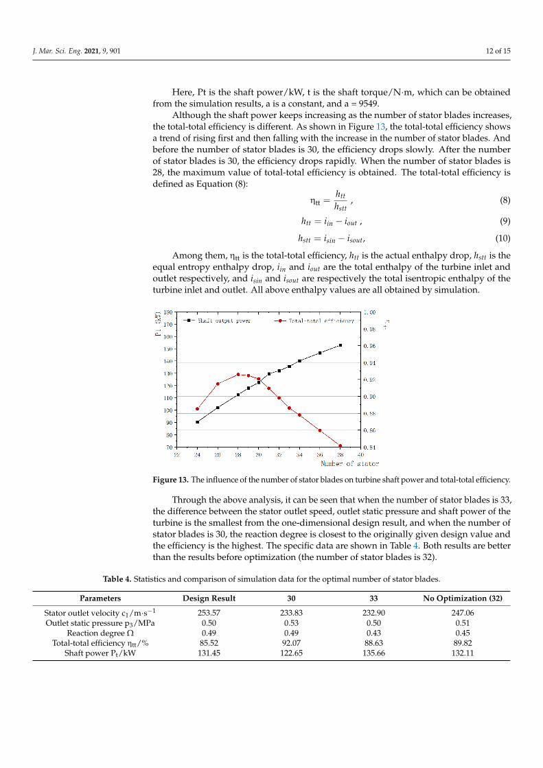
Although the shaft power keeps increasing as the number of stator blades increases,
the total‐total efficiency is different. As shown in Figure 13, the total‐total efficiency shows
a trend of rising first and then falling with the increase in the number of stator blades.
And before the number of stator blades is 30, the efficiency drops slowly. After the number
of stator blades is 30, the efficiency drops rapidly. When the number of stator blades is 28,
the maximum value of total‐total efficiency is obtained. The total‐total efficiency is defined
as Equation (8):
ηℎℎ
, (8)
ℎ 𝑖 𝑖 , (9)
ℎ 𝑖 𝑖 , (10)
Among them, η is the total‐total efficiency, ℎ is the actual enthalpy drop, ℎ is
the equal entropy enthalpy drop, 𝑖 and 𝑖 are the total enthalpy of the turbine inlet
and outlet respectively, and 𝑖 and 𝑖 are respectively the total isentropic enthalpy
of the turbine inlet and outlet. All above enthalpy values are all obtained by simulation.
Figure 12. The influence of the number of stator blades on the enthalpy of the turbine inlet and outlet,the enthalpy of the stator outlet and the shaft power.
J. Mar. Sci. Eng. 2021, 9, 901 12 of 15
Here, Pt is the shaft power/kW, t is the shaft torque/N·m, which can be obtainedfrom the simulation results, a is a constant, and a = 9549.
Although the shaft power keeps increasing as the number of stator blades increases,the total-total efficiency is different. As shown in Figure 13, the total-total efficiency showsa trend of rising first and then falling with the increase in the number of stator blades. Andbefore the number of stator blades is 30, the efficiency drops slowly. After the numberof stator blades is 30, the efficiency drops rapidly. When the number of stator blades is28, the maximum value of total-total efficiency is obtained. The total-total efficiency isdefined as Equation (8):
ηtt =htt
hstt, (8)
htt = iin − iout , (9)
hstt = isin − isout, (10)
Among them, ηtt is the total-total efficiency, htt is the actual enthalpy drop, hstt is theequal entropy enthalpy drop, iin and iout are the total enthalpy of the turbine inlet andoutlet respectively, and isin and isout are respectively the total isentropic enthalpy of theturbine inlet and outlet. All above enthalpy values are all obtained by simulation.
J. Mar. Sci. Eng. 2021, 9, x FOR PEER REVIEW 13 of 16
Figure 12. The influence of the number of stator blades on the enthalpy of the turbine inlet and
outlet, the enthalpy of the stator outlet and the shaft power.
Although the shaft power keeps increasing as the number of stator blades increases,
the total‐total efficiency is different. As shown in Figure 13, the total‐total efficiency shows
a trend of rising first and then falling with the increase in the number of stator blades.
And before the number of stator blades is 30, the efficiency drops slowly. After the number
of stator blades is 30, the efficiency drops rapidly. When the number of stator blades is 28,
the maximum value of total‐total efficiency is obtained. The total‐total efficiency is defined
as Equation (8):
ηℎℎ
, (8)
ℎ 𝑖 𝑖 , (9)
ℎ 𝑖 𝑖 , (10)
Among them, η is the total‐total efficiency, ℎ is the actual enthalpy drop, ℎ is
the equal entropy enthalpy drop, 𝑖 and 𝑖 are the total enthalpy of the turbine inlet
and outlet respectively, and 𝑖 and 𝑖 are respectively the total isentropic enthalpy
of the turbine inlet and outlet. All above enthalpy values are all obtained by simulation.
Figure 13. The influence of the number of stator blades on turbine shaft power and total-total efficiency.
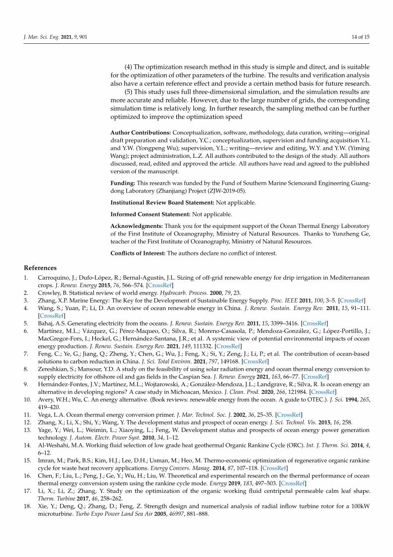
Through the above analysis, it can be seen that when the number of stator blades is 33,the difference between the stator outlet speed, outlet static pressure and shaft power of theturbine is the smallest from the one-dimensional design result, and when the number ofstator blades is 30, the reaction degree is closest to the originally given design value andthe efficiency is the highest. The specific data are shown in Table 4. Both results are betterthan the results before optimization (the number of stator blades is 32).
Table 4. Statistics and comparison of simulation data for the optimal number of stator blades.
Parameters Design Result 30 33 No Optimization (32)
Stator outlet velocity c1/m·s−1 253.57 233.83 232.90 247.06Outlet static pressure p3/MPa 0.50 0.53 0.50 0.51
Reaction degree Ω 0.49 0.49 0.43 0.45Total-total efficiency ηtt/% 85.52 92.07 88.63 89.82
Shaft power Pt/kW 131.45 122.65 135.66 132.11

J. Mar. Sci. Eng. 2021, 9, 901 13 of 15
4. Discussion
Through the above analysis, it can be seen that when the number of stator blades is30 and 33, both have obvious advantages to a certain extent, and it is impossible to judgewhich result is the best through a standard. In order to further verify the analysis andensure the scientificity of the results, the outlet boundary of the turbine was changed tostatic pressure 0.5 MPa, and other conditions were kept unchanged, and then the simulationwas carried out, while paying attention to the outlet mass flow rate and turbine efficiency.The simulation data of the number of stator blades of 30 and 33 under the pressure inlet topressure outlet conditions are obtained.
The comparison of simulation results is shown in Table 5. Under the boundaryconditions of pressure inlet and pressure outlet, it can be seen from the comparison betweenthe two sets of data in the table and the design value that when the number of stator bladesis 33, the difference between the outlet mass flow and the design value is smaller. At thesame time, comparing the two sets of data with the same number of stator blades underdifferent import and export conditions, it can be seen that when the number of statorblades is 33, the two sets of data show better consistency, that is, when the inlet and outletboundary conditions of the turbine are changed, the turbine can still show good workingperformance, and the robustness of the turbine is better.
Table 5. Comparative analysis of verification results.
Boundary Conditions One-DimensionalDesignResult
P to M 1 P to P 2
Number of Stator Blades 30 33 30 33
Stator outlet velocity c1/m·s−1 253.57 233.83 232.90 251.72 253.88Outlet static pressure of p3/MPa 0.5 0.53 0.50 0.5 0.5
Mass flow.
m/kg·s−1 2.44 2.44 2.44 2.57 2.44Reaction degree Ω 0.49 0.49 0.43 0.4335 0.4282
Total-total efficiency ηtt/% 85.52 92.07 88.63 90.15 89.46Shaft power Pt/kW 131.45 122.65 135.66 143.31 135.74
1 Pressure inlet to mass flow outlet. 2 Pressure inlet to pressure outlet.
After verification and analysis, combined with the optimization results of 3 sections, itcan be concluded that under the design conditions, when the number of stator blades is 33,the performance of the turbine is the best.
5. Conclusions
In this paper, through the optimization of the number of stator blades of a radial inflowturbine with a 100 kW ammonia working fluid converted from ocean thermal energy, thefollowing conclusions are obtained:
(1) Within a certain range, as the number of stator blades increases, the outlet pressureand outlet enthalpy of the turbine will decrease, and the shaft power will increase accordingly.
(2) Within a certain range, with the increase in the number of stator blades, theturbine stator outlet speed gradually increases. Outlet speed that is too slow will resultin countercurrents and eddy currents at the inlet of the moving rotor, but an excessivelylarge stator outlet speed will also have an impact on the moving rotor and increase the loss.Therefore, the total-total efficiency shows a trend of rising first and then falling with theincrease in the number of stator blades.
(3) After optimization analysis and verification comparison, there is an optimal num-ber of stator blades under design conditions to make the pressure field and velocity fieldthe best, and at the same time obtain higher output power, efficiency and robustness. Theoptimal number of stator blades is 33. At this time, the efficiency is 89.46%, which is3.94% higher than the design value, and the output power is 135.74kW, which meets thedesign requirements.
J. Mar. Sci. Eng. 2021, 9, 901 14 of 15
(4) The optimization research method in this study is simple and direct, and is suitablefor the optimization of other parameters of the turbine. The results and verification analysisalso have a certain reference effect and provide a certain method basis for future research.
(5) This study uses full three-dimensional simulation, and the simulation results aremore accurate and reliable. However, due to the large number of grids, the correspondingsimulation time is relatively long. In further research, the sampling method can be furtheroptimized to improve the optimization speed
Author Contributions: Conceptualization, software, methodology, data curation, writing—originaldraft preparation and validation, Y.C.; conceptualization, supervision and funding acquisition Y.L.and Y.W. (Yongpeng Wu); supervision, Y.L.; writing—review and editing, W.Y. and Y.W. (YimingWang); project administration, L.Z. All authors contributed to the design of the study. All authorsdiscussed, read, edited and approved the article. All authors have read and agreed to the publishedversion of the manuscript.
Funding: This research was funded by the Fund of Southern Marine Scienceand Engineering Guang-dong Laboratory (Zhanjiang) Project (ZJW-2019-05).
Institutional Review Board Statement: Not applicable.
Informed Consent Statement: Not applicable.
Acknowledgments: Thank you for the equipment support of the Ocean Thermal Energy Laboratoryof the First Institute of Oceanography, Ministry of Natural Resources. Thanks to Yunzheng Ge,teacher of the First Institute of Oceanography, Ministry of Natural Resources.
Conflicts of Interest: The authors declare no conflict of interest.
References1. Carroquino, J.; Dufo-López, R.; Bernal-Agustín, J.L. Sizing of off-grid renewable energy for drip irrigation in Mediterranean
crops. J. Renew. Energy 2015, 76, 566–574. [CrossRef]2. Crowley, B. Statistical review of world energy. Hydrocarb. Process. 2000, 79, 23.3. Zhang, X.P. Marine Energy: The Key for the Development of Sustainable Energy Supply. Proc. IEEE 2011, 100, 3–5. [CrossRef]4. Wang, S.; Yuan, P.; Li, D. An overview of ocean renewable energy in China. J. Renew. Sustain. Energy Rev. 2011, 15, 91–111.
[CrossRef]5. Bahaj, A.S. Generating electricity from the oceans. J. Renew. Sustain. Energy Rev. 2011, 15, 3399–3416. [CrossRef]6. Martínez, M.L.; Vázquez, G.; Pérez-Maqueo, O.; Silva, R.; Moreno-Casasola, P.; Mendoza-González, G.; López-Portillo, J.;
MacGregor-Fors, I.; Heckel, G.; Hernández-Santana, J.R.; et al. A systemic view of potential environmental impacts of oceanenergy production. J. Renew. Sustain. Energy Rev. 2021, 149, 111332. [CrossRef]
7. Feng, C.; Ye, G.; Jiang, Q.; Zheng, Y.; Chen, G.; Wu, J.; Feng, X.; Si, Y.; Zeng, J.; Li, P.; et al. The contribution of ocean-basedsolutions to carbon reduction in China. J. Sci. Total Environ. 2021, 797, 149168. [CrossRef]
8. Zereshkian, S.; Mansour, Y.D. A study on the feasibility of using solar radiation energy and ocean thermal energy conversion tosupply electricity for offshore oil and gas fields in the Caspian Sea. J. Renew. Energy 2021, 163, 66–77. [CrossRef]
9. Hernández-Fontes, J.V.; Martínez, M.L.; Wojtarowski, A.; González-Mendoza, J.L.; Landgrave, R.; Silva, R. Is ocean energy analternative in developing regions? A case study in Michoacan, Mexico. J. Clean. Prod. 2020, 266, 121984. [CrossRef]
10. Avery, W.H.; Wu, C. An energy alternative. (Book reviews: renewable energy from the ocean. A guide to OTEC.). J. Sci. 1994, 265,419–420.
11. Vega, L.A. Ocean thermal energy conversion primer. J. Mar. Technol. Soc. J. 2002, 36, 25–35. [CrossRef]12. Zhang, X.; Li, X.; Shi, Y.; Wang, Y. The development status and prospect of ocean energy. J. Sci. Technol. Vis. 2015, 16, 258.13. Yage, Y.; Wei, L.; Weimin, L.; Xiaoying, L.; Feng, W. Development status and prospects of ocean energy power generation
technology. J. Autom. Electr. Power Syst. 2010, 34, 1–12.14. Al-Weshahi, M.A. Working fluid selection of low grade heat geothermal Organic Rankine Cycle (ORC). Int. J. Therm. Sci. 2014, 4,
6–12.15. Imran, M.; Park, B.S.; Kim, H.J.; Lee, D.H.; Usman, M.; Heo, M. Thermo-economic optimization of regenerative organic rankine
cycle for waste heat recovery applications. Energy Convers. Manag. 2014, 87, 107–118. [CrossRef]16. Chen, F.; Liu, L.; Peng, J.; Ge, Y.; Wu, H.; Liu, W. Theoretical and experimental research on the thermal performance of ocean
thermal energy conversion system using the rankine cycle mode. Energy 2019, 183, 497–503. [CrossRef]17. Li, X.; Li, Z.; Zhang, Y. Study on the optimization of the organic working fluid centripetal permeable calm leaf shape.
Therm. Turbine 2017, 46, 258–262.18. Xie, Y.; Deng, Q.; Zhang, D.; Feng, Z. Strength design and numerical analysis of radial inflow turbine rotor for a 100kW
microturbine. Turbo Expo Power Land Sea Air 2005, 46997, 881–888.

J. Mar. Sci. Eng. 2021, 9, 901 15 of 15
19. Li, Y.; Gu, C. Research on aerodynamic optimization of a centripetal turbine with a high expansion ratio organic working fluid.J. Eng. Thermophys. 2013, 34, 1239–1242.
20. Tan, X.; Guo, H.J.; Li, H.; Huang, D.G. Centrifugal turbine blade design based on NURBS curve. J. Therm. Energy Power Eng. 2017,32, 47–53.
21. Wang, X.; Liu, X. Response surface analysis and optimization of organic working fluid turboexpander stator. J. Xi’an Jiaotong Univ.2015, 49, 7–13.
22. Song, P.; Sun, J.; Wang, K.; He, Z. Development of an optimization design method for turbomachinery by incorporating thecooperative coevolution genetic algorithm and adaptive approximate model. In Proceedings of the ASME 2011 Turbo Expo:Turbine Technical Conference and Exposition, Vancouver, BC, Canada, 6–10 June 2011.
23. Al Jubori, A.M.; Al-Dadah, R.; Mahmoud, S. Performance enhancement of a small-scale organic Rankine cycle radial-inflowturbine through multi-objective optimization algorithm. Energy 2017, 131, 297–311. [CrossRef]
24. Liu, W.; Ge, Y.; Liu, L.; Chen, Y. Current Development and Prospect of Turbine in OTEC. 2020. Available online: https://library.oapen.org/bitstream/handle/20.500.12657/43849/external_content.pdf?sequence=1#page=65 (accessed on 19 August 2021).
25. Liu, W.M.; Chen, F.Y.; Wang, Y.Q.; Jiang, W.J.; Zhang, J.G. Progress of Closed-Cycle OTEC and c of OTEC. J. Adv. Mater. Res. 2012,354, 275–278. [CrossRef]
26. Chen, F.; Zhang, L.; Liu, W.; Liu, L.; Peng, J. Thermodynamic Analysis of Rankine Cycle in Ocean Thermal Energy Conversion.Int. J. Simul. Syst. 2016, 17, 7.1–7.4.
27. Li, Y.; Lu, G. Radial Inflow Turbine and Centrifugal Compressor, 1st ed.; Machinery Industry Press: Beijing, China, 1992; pp. 110–132.28. Xu, Z.W.; Guo, H.Y.; Zheng, Z.J.; Jiang, X.H.; Zheng, Y. Improvement of Design Technology for a Radial Inflow Turbine Guide
Vane and Its Application. Tuijin Jishu J. Propuls. Technol. 2017, 38, 2358–2364.29. Chen, Y.; Liu, Y.; Zhang, L.; Yang, X. Three-dimensional performance analysis of a radial–inflow turbine for ocean thermal energy
conversion system. J. Mar. Sci. Eng. 2021, 9, 287. [CrossRef]30. Higashi, Y. NIST thermodynamic and transport properties of refrigerants and refrigerant mixtures (REFPROP). J. Netsu Bussei
2000, 14, 1575–1577.31. Zhang, J.H.; Zhou, Z.G. Aerodynamic Optimization Design of Radial Turbine Based on Parallel Genetic Algorithm. Aeroengine
2015, 41, 39–43.32. Bekiloglu, H.E.; Bedir, H.; Anlas, G. Multi-objective optimization of ORC parameters and selection of working fluid using
preliminary radial inflow turbine design. J. Energy Convers. Manag. 2019, 183, 833–847. [CrossRef]33. Rocha, P.C.; Rocha, H.B.; Carneiro, F.M.; da Silva, M.V.; Bueno, A.V. k–ω SST (shear stress transport) turbulence model calibration:
A case study on a small scale horizontal axis wind turbine. Energy 2014, 65, 412–418. [CrossRef]34. Louda, P.; Svácek, P.; Fort, J.; Fürst, J.; Halama, J.; Kozel, K. Numerical simulation of turbine cascade flow with blade-fluid heat
exchange. Appl. Math. Comput. 2013, 219, 7206–7214. [CrossRef]