Embed Size (px)
Citation preview

INTERNATIONAL JOURNAL ON SMART SENSING AND INTELLIGENT SYSTEMS VOL. 7, NO. 3, SEPTEMBER 2014
1174
RESEARCH ON LQR ZONE CONTROL ALGORITHM
FOR PICKING ROBOT ARM
1Zhang Zhiyong,
1* Huang Lvwen,
1Xu Yang,
1Zhang Xiaoting
1,College of information Engineering
Northwest A&F University, Yangling, Shaanxi, 712100, China
E-mail: [email protected],
Submitted: May 3, 2014 Accepted: July 10, 2014 Published: Sep. 1, 2014
Abstract- This paper aims at improve the poor stability and the fluttering problems on picking apples
for picking robot arm, we establish the dynamics model of Picking Robot Arm using Lagrange equation
and divide the whole movement space of Picking Robot Arm into stretch area and picking area by
analyzing the dynamic model. Making full using of the model, we put forward to the strategy based on
the extension energy control and LQR Zone control. Furthermore, we solve the problem on ensuring
the picking robot arm’s energy increasing for the picking stretch process. The energy stability control
study on establishing the robust performance analysis and design in theory lays a foundation for other
relevant stability study.
Index terms: Picking Robot Arm, the zone control, dynamic model, LQR.
Zhang Zhiyong, Huang Lvwen, Xu Yang, Zhang Xiaoting, RESEARCH ON LQR ZONE CONTROL ALGORITHM
FOR PICKING ROBOT ARM
1175
I. INTRODUCTION
It is necessary to control the contact force applied to picking environment at the contact point,
fluttering control is required when using a flexible arm for such a complex picking task.
Furthermore link flexibility may contribute to the instability problem in arm control. Many
researchers have investigated the fluttering control of picking arms based on a finite-dimensional
approximated model [1–2]; this has meant, however, that the findings obtained in these studies
are confined to the finite-dimensional approximated model. The dimension of the controller
increases along with an increase in the number of modes provided in the controller design model.
Furthermore, fluttering, which results from a neglected high-frequency characteristic, makes such
systems unstable. For these reasons, it is both desirable and of interest to consider the force
control of a flexible arm using the infinite dimensional model. In contrast to investigations based
on the finite-dimensional approximated model, there are only a few studies based on the infinite
dimensional model.
At present, many control methods such as Variable structure control, Adaptive control, Singular
perturbation control et al. has been applied in picking robot arm stability control area. It is
difficult to meet the requirements of system control only through a control strategy due to the
characteristics of arm length, wide range of motion, multiple joint and multiple degrees of
freedom for picking apples [3]. Based on the analysis of characteristics of the joint movement
which alike man's gripper, we adopt the different tactics to achieve partition control to make the
picking robot arm reach apple picking area stably and pick the ripe apple without fluttering
according to the joint torque and rotation angle. It can be provided theoretical reference and
technological reference for relevant control problems. In the kinematics of picking robot arm, we
also can calculate each joint turning angle by solving motion equations according to the position
of picking gripper while it reaching the picking area. So each joint movement is not independent,
but connected and coordinated. Actually the picking movement of picking robot arm is controlled
respectively by their own joint axis servo, so the picking movement must be decomposed to the
velocity, acceleration, force of joint axis, the actuators moment must be broken down into the
speed, acceleration, force or moment of joint shaft, and be completed the movement by
independent control servo system of each joint. However, the servo control system often is
completed in the joint coordinate system. According to the experience of the related majority
Zhang Zhiyong, Huang Lvwen, Xu Yang, Zhang Xiaoting, RESEARCH ON LQR ZONE CONTROL ALGORITHM
FOR PICKING ROBOT ARM
1176
literature [4-6], we usually apply the Cartesian coordinates to indicate the end actuator position,
so it is necessary to control motion parameters including velocity, acceleration and force (torque)
of the movement decomposition.
(1) Speed control of movement decomposition
In order to ensure picking robot arm joint stable operation in the Cartesian axes, the speed control
needs to drive joint motors joint run with the respective real-time velocity at the same time.
During the control of movement decomposition, firstly we gain the expected joint velocity by
decomposing the Descartes position, and then implement the stability control of servo. In
Cartesian coordinates, the position of 3-DOF picking robot arm can be represented as
T
X Y ZX(t) P P P (1)
But the generalized coordinate vector is also represented
1 2
T
nq(t) q q q (2)
The relation between equation (1) and equation (2) can be represented as
X(t) f(q) (3)
The relationship of the joint angle and the Cartesian coordinate can be expressed in equation (3),
then derivations equation (3), we can gain
. .
( ) (X(t) J q q t) (4)
Where ( )J q denotes generalized Jacobi matrix,.
X(t) denotes expectations speed of picking
arms in Cartesian coordinates,.
(q t) denotes the joint speed in joint space.
(1 ,1 )iij
i
fJ i m j m
q
(5)
equation (5) represents the corresponding relations on two kinds of speed, we could should
discuss the relation about the freedom degree m and the space movement freedom degree n in
order to get the mathematical expression of .
(q t) corresponding to the.
X(t) . If m=n which denotes
the picking robot arm freedom degree and the picking space freedom degree are equal, picking
robot arm freedom degree is redundant, and we can solve the inverse matrix of its Jacobi matrix
directly . .
-1(q t) J (q) X(t) (6)

Zhang Zhiyong, Huang Lvwen, Xu Yang, Zhang Xiaoting, RESEARCH ON LQR ZONE CONTROL ALGORITHM
FOR PICKING ROBOT ARM
1177
If m<n, which represents that picking robot arm have not the redundant freedom degree, we can
solve its generalized inverse matrix
( ) ( )q t J (q)X t (7)
Where, J (q) denotes generalized inverse matrix equation (7) is the least squares solution of
equation (6), if ( )J q is a full rank matrix, then there exist following equation
T T 1( ) ( ) [ ( ) ( ) ] J q J q J q J q (8)
According to equation (7), the solution of J (q) can simplify following equation.
-1(T TJ J JJ ) (9)
Equation (6) and equation (7) represent picking robot arm joint velocity respectively on the
condition of redundancy and non-redundancy. We can structure the picking robot arm motion
control scheme according to these two equations and decompose the picking robot arm
movement into the joint movement. So the control method is referred to speed control of
movement decomposition.
(2) Acceleration control of movement decomposition
The acceleration control of movement decomposition is the extensiveness of the speed control.
Its method is that we can decompose the acceleration in the Cartesian coordinates into the
corresponding joint acceleration, then we can solve the control moment which apply to the joint
motor according to the corresponding system dynamics model. By solving the derivative of
equation (6), we can gain the picking robot arm acceleration
( ) ( ) ( ) ( )X t J t q t Jq t (10)
Equation (10) represents the corresponding acceleration relations in the Cartesian coordinates and
the joint coordinate system, namely the decomposition control of the desired acceleration in the
Cartesian coordinates. The target of acceleration control is virtually to make the precision error
between the trajectory and the desired position evaluation converge to zero, now assuming that
de X X (11)
Where, e denotes the precision error between the actual position and the desired evaluation
position, dX denotes the desired position vector , X denotes the actual position vector. In order to
make the desired evaluation converge to zero, the following relations must be satisfied
1 2 0e k e k e (12)
Zhang Zhiyong, Huang Lvwen, Xu Yang, Zhang Xiaoting, RESEARCH ON LQR ZONE CONTROL ALGORITHM
FOR PICKING ROBOT ARM
1178
Where k1,k2 denote the ratio coefficient. The value of the ratio coefficient should make the
characteristic root of the real part be negative. Substituting the equation (10) and equation (11)
into the equation (12), we can gain
1
1 1 2( ) ( ) ( )[ ( ) ( ) ( ) ( , )] ( )dq t k q t J q X t k X t k e t J q q q t (13)
The equation (13) is the theoretical basis on acceleration control of movement decomposition
for closed-loop picking robot arm control. If the path of the picking robot arm in the Cartesian
coordinates is planned in advanced, the desired position, speed and acceleration of the end
actuator in this coordinate system are known. Then we can calculate the acceleration in the joint
coordinate system. Making full using of the speed and acceleration of picking robot arm joint and
its dynamic equation, we can calculate the force or torque belonged to picking robot arm join.
According to dynamic principle [4-7], we can gain the picking robot arm dynamic equation
( ) ( , ) ( )M q q H q q q G q (14)
Where ( )M q denotes inertia matrix of picking robot arm, ( , )H q q denote Centrifugal force and
force vector, ( )G q denotes gravity vector, denotes force and torque vector applying to picking
robot arm joint.
(3) Force and torque control
The basic idea on the force and torque control of the movement decomposition is that we
calculate the control torque applied to driven joint firstly and then control the position and speed
of the picking gripper in the Cartesian coordinates. The theory basis of force and torque control is
the dynamical model and the method is the solution of inverse dynamics. Given that force and
torque control in the arm joint space is closed loop according to the desired gripper, its position in
the Cartesian coordinates is also known, we can gain its corresponding desired position qd in the
joint coordinate system by kinematics calculation and we can also gain the position error in the
arm joint space q
q de q q (15)
In order to make the error between the actual trajectory and the expectation trajectory of picking
robot arm joint space decreases in the process of joint movement until convergence is zero, the
error should be satisfied
1 2 0q q q q qe k e k e (16)

Zhang Zhiyong, Huang Lvwen, Xu Yang, Zhang Xiaoting, RESEARCH ON LQR ZONE CONTROL ALGORITHM
FOR PICKING ROBOT ARM
1179
At the same time, the coefficient of 1qk and 2qk should be a positive and the characteristic root of
equation (16) should be located in the negative half plane. Substituting the equation (15) and
equation (16) into the equation (14), we can gain the following
1 2( ) ) ( , ) ( )d q q q qM q q k e k e H q q q G q ( (17)
Equation(17) represent the calculation method of the force and moment in the control process of
picking robot arm.
II. PICKING ROBOT ARM DYNAMICS MODEL EQUATION
There are some methods of Studying of picking robot arm dynamics such as Lagrange method,
Newton-Euler method, Gauss method, Roberon-Wittenburg method and Kane method and so on
[8,9], all of these methods are benefit to the control of picking robot arm. Lagrange equation is
suitable for the mathematical modeling and simulation of dynamics and kinematics analysis,
because of its mechanical dynamic characteristics owns the characteristics of multi-movement
and multi-freedom degree, it is especially applied in the robot motion mechanics based on the
multi-body dynamics. So we research the picking robot arm dynamics by using Lagrange
equation.
(1) Lagrange equation of picking robot arm
Research literature [9-10] represented that the dynamic equation based on Lagrange theory is
applied to the study of arm dynamic model, its derivation process is simple, and it can clearly
represent the coupling characteristic of arms, and can also directly represent the system control
input function. Therefore we can establish the dynamics equation by using the recursive
Lagrange equation in the form of homogeneous coordinates. For any mechanical system, the
Lagrange method establishing the dynamics equation based on the system of kinetic energy and
potential energy, and this method can avoid mechanism motion analysis. Using the difference
between the total kinetic energy kE and potential energy PE , we can establish the system
Lagrange function L and its concise dynamic equation [11-12]
K PL E E (18)
( 1,2,3)i
i i
d L LF i
dt q q
(19)
Zhang Zhiyong, Huang Lvwen, Xu Yang, Zhang Xiaoting, RESEARCH ON LQR ZONE CONTROL ALGORITHM
FOR PICKING ROBOT ARM
1180
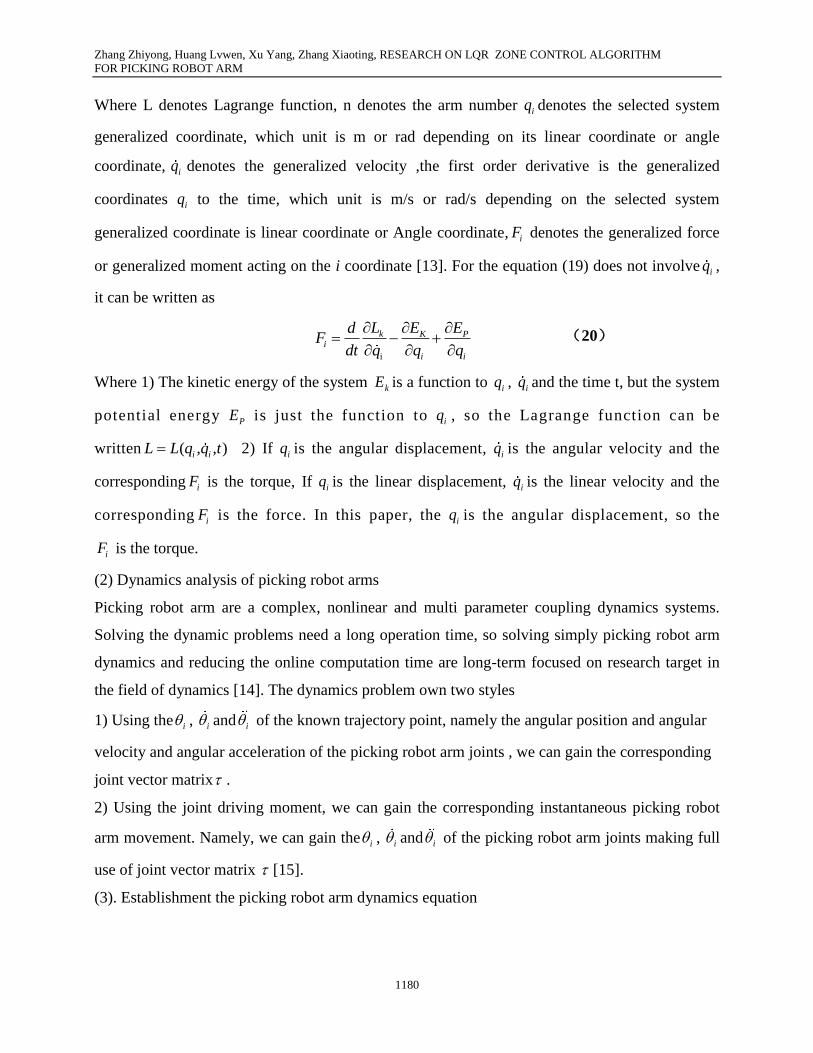
Where L denotes Lagrange function, n denotes the arm number iq denotes the selected system
generalized coordinate, which unit is m or rad depending on its linear coordinate or angle
coordinate, iq denotes the generalized velocity ,the first order derivative is the generalized
coordinates iq to the time, which unit is m/s or rad/s depending on the selected system
generalized coordinate is linear coordinate or Angle coordinate, iF denotes the generalized force
or generalized moment acting on the i coordinate [13]. For the equation (19) does not involve iq ,
it can be written as
i
k K Pi
i i
L E EdF
dt q q q
(20)
Where 1) The kinetic energy of the system kE is a function to iq , iq and the time t, but the system
potential energy PE is just the function to iq , so the Lagrange function can be
written ( , , )i iL L q q t
2) If iq is the angular displacement, iq is the angular velocity and the
corresponding iF is the torque, If iq is the linear displacement, iq is the linear velocity and the
corresponding iF is the force. In this paper, the iq is the angular displacement, so the
iF is the torque.
(2) Dynamics analysis of picking robot arms
Picking robot arm are a complex, nonlinear and multi parameter coupling dynamics systems.
Solving the dynamic problems need a long operation time, so solving simply picking robot arm
dynamics and reducing the online computation time are long-term focused on research target in
the field of dynamics [14]. The dynamics problem own two styles
1) Using the i , i and i of the known trajectory point, namely the angular position and angular
velocity and angular acceleration of the picking robot arm joints , we can gain the corresponding
joint vector matrix .
2) Using the joint driving moment, we can gain the corresponding instantaneous picking robot
arm movement. Namely, we can gain the i , i and i of the picking robot arm joints making full
use of joint vector matrix [15].
(3). Establishment the picking robot arm dynamics equation
Zhang Zhiyong, Huang Lvwen, Xu Yang, Zhang Xiaoting, RESEARCH ON LQR ZONE CONTROL ALGORITHM
FOR PICKING ROBOT ARM
1181
As a complex system, we generally adopt the homogeneous transformation to set up the system
dynamics equation by using the Lagrange equation and describe its pose and motion state. Now,
we can study the derivation process of dynamics equation referring to Figure 1. The system
variables definition and experimental parameters are shown in table 1. On the convenience of
research, we make the following assumptions
1) Picking robot arm are rigid bodies, the control objects input is just the output torque of the
joint motor.
2) Ignoring air resistance and various frictions.
3) Part between the shoulder and elbow called the upper arm and part between elbow and wrist
joints is called the forearm can all be abstracted to homogeneous bar.
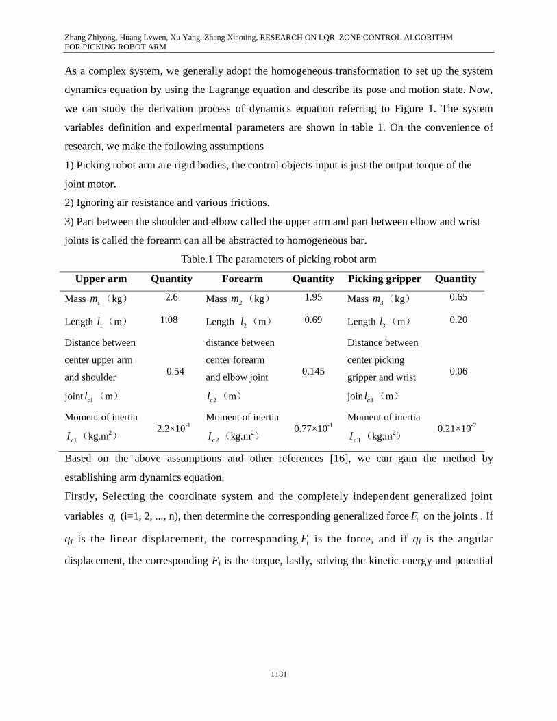
Table.1 The parameters of picking robot arm
Upper arm Quantity Forearm Quantity Picking gripper Quantity
Mass 1m (kg) 2.6 Mass 2m (kg) 1.95 Mass 3m (kg) 0.65
Length 1l (m) 1.08 Length 2l (m) 0.69 Length 3l (m) 0.20
Distance between
center upper arm
and shoulder
joint 1cl (m)
0.54
distance between
center forearm
and elbow joint
2cl (m)
0.145
Distance between
center picking
gripper and wrist
join 3cl (m)
0.06
Moment of inertia
1cI (kg.m2)
2.2×10⁻¹
Moment of inertia
2cI (kg.m2)
0.77×10⁻¹
Moment of inertia
3cI (kg.m2)
0.21×10⁻²
Based on the above assumptions and other references [16], we can gain the method by
establishing arm dynamics equation.
Firstly, Selecting the coordinate system and the completely independent generalized joint
variables iq (i=1, 2, ..., n), then determine the corresponding generalized force iF on the joints . If
qi is the linear displacement, the corresponding iF is the force, and if qi is the angular
displacement, the corresponding Fi is the torque, lastly, solving the kinetic energy and potential
Zhang Zhiyong, Huang Lvwen, Xu Yang, Zhang Xiaoting, RESEARCH ON LQR ZONE CONTROL ALGORITHM
FOR PICKING ROBOT ARM
1182
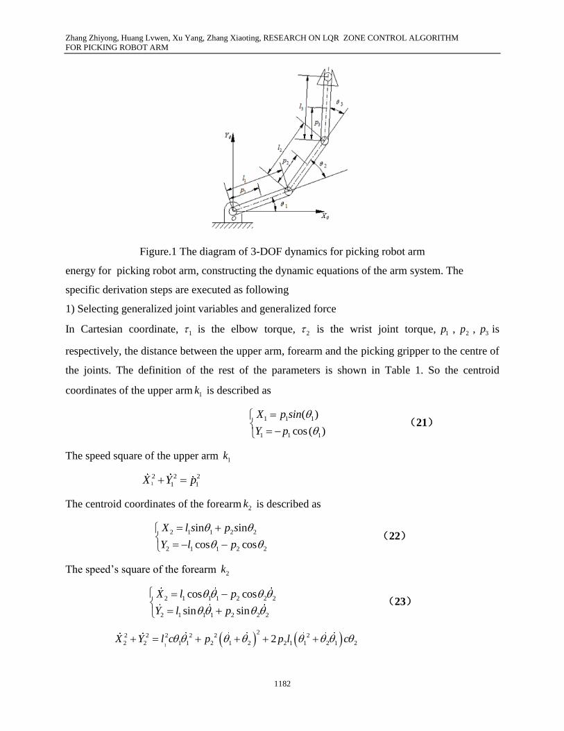
Figure.1 The diagram of 3-DOF dynamics for picking robot arm
energy for picking robot arm, constructing the dynamic equations of the arm system. The
specific derivation steps are executed as following
1) Selecting generalized joint variables and generalized force
In Cartesian coordinate, 1 is the elbow torque, 2 is the wrist joint torque, 1p , 2p , 3p is
respectively, the distance between the upper arm, forearm and the picking gripper to the centre of
the joints. The definition of the rest of the parameters is shown in Table 1. So the centroid
coordinates of the upper arm 1k is described as
1 1 1
1 1 1
( )
cos ( )
X p sin
Y p
(21)
The speed square of the upper arm 1k
1
2 2 2
1 1X Y p
The centroid coordinates of the forearm 2k is described as
2 1 1 2 2
2 1 1 2 2
in in
cos cos
X l s p s
Y l p
(22)
The speed’s square of the forearm 2k
2 1 1 1 2 2 2
2 1 1 1 2 2 2
cos cos
sin sin
X l p
Y l p
(23)
1
22 2 2 2 2 2
2 2 1 1 2 1 2 2 1 1 2 1 22X Y l c p p l c
Zhang Zhiyong, Huang Lvwen, Xu Yang, Zhang Xiaoting, RESEARCH ON LQR ZONE CONTROL ALGORITHM
FOR PICKING ROBOT ARM
1183
The centroid coordinates of the mass center of picking gripper 3k is described as
2 1 1 2 2 3 3
3 1 1 2 2 3 3
in sin sin
cos cos cos
X l s l p
Y l l p
(24)
The speed’s square of the mass center of picking gripper 3k is
3 1 1 1 2 2 1 2 3 3 1 2 3
3 1 1 1 2 2 1 2 3 3 1 2 3
os cos cos ( )
sin sin sin ( )
X l c l p
Y l l p
(25)
1
22 2 2 2 2 2 2 2
3 3 1 1 2 1 2 2 1 1 2 1 2 3 1 2 1 2 1 3 2cos 2 cos 3 cosX Y l l l l p l l
2) Solving the system’s kinetic energy
( 1,2,3)k kiE E i (26)
1
2 2
1 1 1 1
2 2 2 2 2 2
2 2 1 1 2 2 1 21 2 2 2 1 1 2 2
22 2 2 2 2 2
3 2 1 1 2 1 2 2 1 1 2 1 2 3 1 2 1 2 1 3 2
1
2
1 1( ) ( ) cos
2 2
1( cos 2 cos 3 cos )
2
k
k
k
E m p
E m l m p m l p
E m l l l l p l l
3) Solving the system potential energy
1,2,3p piE E i ( ) (27)
1 1 1 1
2 1 1 1 2 2 2
3 1 1 1 2 2 2 2 2 3
(1 cos )
(1 cos ) (1 cos )
(1 cos ) (1 cos ) (1 cos )
p
p
p
E m gp
E m gl m gp
E m gl m gl m gp
4) Solving the system research function
1 2 3 1 2 3
1
22 2 2 2 2 2
2 1 1 2 1 2 2 1 1 2 1 2 3 1 2 1 2 1 3 2
2 2 2 2 2 2
2 2 12 1 1 2 1 1 2 1 2 1 1 2 2 2 2 1 2
1 1 2
( )
1( cos 2 cos 3 cos )
2
1 1(1 ) ( ) ( ) ( )
2 2
(
k p k k k p p pL E E E E E E E E
m l l l l p l l
m p g c m p m l m l p c m p
m p m l
1 1 1 1 1 2 2 2 2 2 3) (1 os ) (1 cos ) (1 cos ) (1 cosg c m gl m gl m gp )
5) Solving the System dynamics equation
We can calculate the torque represent joint and the dynamics equation of the control system for
picking robot arm by the equation (20).
Zhang Zhiyong, Huang Lvwen, Xu Yang, Zhang Xiaoting, RESEARCH ON LQR ZONE CONTROL ALGORITHM
FOR PICKING ROBOT ARM
1184
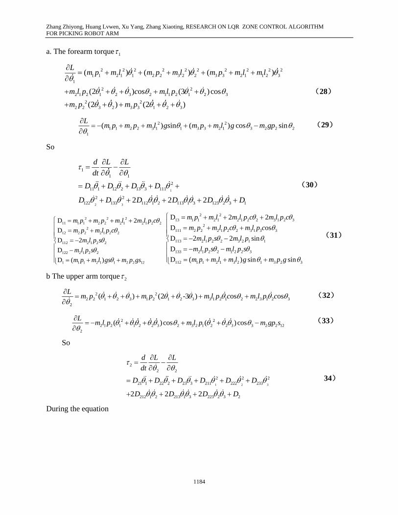
a. The forearm torque 1
2 2 2 2 2 2 2 2 2 2
1 1 2 1 1 2 2 3 2 2 3 3 2 1 1 2 3
1
2 2
2 1 2 1 2 3 2 1 1 2 1 2 3
2 2
2 2 3 2 3 3 1 2 3
( ) ( ) ( )
(2 ) os (3 )cos
(2 ) (2 )
Lm p m l m p m l m p m l m l
m l p c m l p
m p m p
(28)
2 2
1 1 2 2 3 1 1 3 3 2 1 3 2 2 2
1
( ) in ( ) cos sinL
m p m p m l gs m p m l g m gp
(29)
So
1
2 3
1
1 1
2
11 1 12 2 13 3 111
2 2
122 133 112 1 2 113 1 3 123 2 3 12 2 2
d L L
dt
D D D D
D D D D D D
(30)
2 2 2
11 1 1 2 2 2 1 2 1 2 2
2
12 2 2 2 1 2 2
112 2 1 2 2
122 2 1 2 2
1 1 1 2 1 1 2 2 12
D 2
D
D 2
D
D ( )
m p m p m l m l p c
m p m l p c
m l p s
m l p s
m p m l gs m p gs
2 2
13 1 1 2 1 2 1 2 2 3 1 2 3
2
111 2 2 2 1 2 2 3 1 3 3
113 2 1 2 2 3 2 1 1
133 2 1 2 2 1 2 2 3
112 1 1 2 1 3 2 1 3 2 3
D 2 2
D os
D 2 2 sin
D
D ( ) sin sin
m p m l m l p c m l p c
m p m l p c m l p c
m l p s m l p
m l p s m l p s
m p m l m l g m p g
(31)
b The upper arm torque 2
2 2
2 2 1 2 3 1 2 1 2 3 3 1 2 1 2 2 3 1 2 3
2
( ) (2 -3 ) os osL
m p m p m l p c m l p c
(32)
2 2
2 1 2 1 1 2 2 3 2 3 2 1 2 2 3 3 2 2 12
2
( )cos ( )cosL
m l p m l p m gp s
(33)
So
1 2 3
2
2 2
2 2 2
21 1 22 2 23 3 211 222 233
212 1 2 213 1 3 223 2 3 22 2 2
d L L
dt
D D D D D D
D D D D
34)
During the equation
Zhang Zhiyong, Huang Lvwen, Xu Yang, Zhang Xiaoting, RESEARCH ON LQR ZONE CONTROL ALGORITHM
FOR PICKING ROBOT ARM
1185
2
21 2 2 2 1 2 2
2
22 2 2
212 2 1 2 2 2 1 2 2
211 2 1 2 2
2 2 2 12
0
D m p m l p c
D m p
D m l p s m l p s
D m l p s
D m gp s
2 2 2
23 2 1 3 3 2 1 2 1 2 1 2
2
211 2 2 3 2 2 2 3
213 2 1 2 2 3 1 3 2 3
233 2 1 2 2 3
212 1 1 2 1 1 3 3 1
D 2 os os
D cos cos
D 2 sin 3 sin sin
D sin sin
D ( ) sin
m p m p m l m l p c c
m p m l p
m l p m l p
m l p
m p m l gs m p g
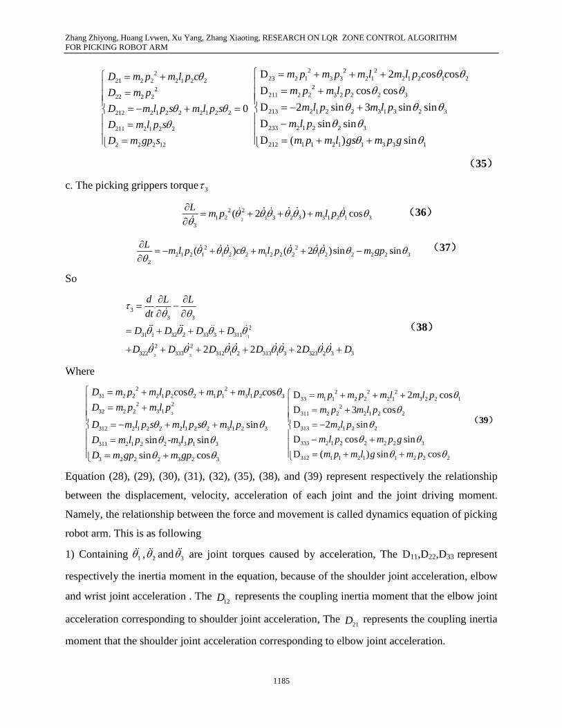
(35)
c. The picking grippers torque 3
2
2 2
1 2 1 3 2 3 3 1 2 1 3
3
( 2 ) cosL
m p m l p
(36)
2 2
2 1 2 1 1 2 2 1 2 2 2 1 2 2 2 2 3
2
( ) ( 2 )sin sinL
m l p c m l p m gp
(37)
So
1
2 3
3
3 3
2
31 1 32 2 33 3 311
2 2
322 333 312 1 2 313 1 3 323 2 3 32 2 2
d L L
dt
D D D D
D D D D D D
(38)
Where
3
2 2
31 2 2 2 1 2 2 1 1 3 1 2 3
2 2
32 2 2 3 1
312 2 1 2 2 2 1 2 2 3 1 2 3
311 2 1 2 2 3 3 1 3
3 2 2 2 3 2 3
os os
sin
sin - sin
sin cos
D m p m l p c m p m l p c
D m p m l p
D m l p s m l p s m l p
D m l p m l p
D m gp m gp
2 2 2
33 1 1 2 2 2 1 3 2 2 1
2
311 2 2 2 1 2 2
313 2 1 2 2
333 2 1 2 2 2 2 3
312 1 1 2 1 1 2 2 2
D 2 cos
D 3 cos
D 2 sin
D cos sin
D ( ) sin cos
m p m p m l m l p
m p m l p
m l p
m l p m p g
m p m l g m p
(39)
Equation (28), (29), (30), (31), (32), (35), (38), and (39) represent respectively the relationship
between the displacement, velocity, acceleration of each joint and the joint driving moment.
Namely, the relationship between the force and movement is called dynamics equation of picking
robot arm. This is as following
1) Containing 1 , 2 and 3 are joint torques caused by acceleration, The D11,D22,D33 represent
respectively the inertia moment in the equation, because of the shoulder joint acceleration, elbow
and wrist joint acceleration . The 12D represents the coupling inertia moment that the elbow joint
acceleration corresponding to shoulder joint acceleration, The 21D represents the coupling inertia
moment that the shoulder joint acceleration corresponding to elbow joint acceleration.

Zhang Zhiyong, Huang Lvwen, Xu Yang, Zhang Xiaoting, RESEARCH ON LQR ZONE CONTROL ALGORITHM
FOR PICKING ROBOT ARM
1186
2) Containing 2
1 , 2
2 and 2
3 are joint torques caused by centripetal force, in the equations, the
122D represents the coupling inertia moment that the centripetal force caused by the elbow joint
speed corresponding to shoulder joint, The 211D represents the coupling inertia moment that the
centripetal force caused by the shoulder joint speed corresponding to elbow joint, The 322D
represents the coupling inertia moment that the centripetal force caused by the elbow joint speed
corresponding to wrist joint.
3) Containing 1 2 3 are joint torques caused by Coriolis force, in the equations, the 112D
represent the coupling inertia moment that the Coriolis force corresponding to shoulder joint, the
212D represents the coupling inertia moment that the Coriolis force corresponding to elbow joint,
the 213D represents the coupling inertia moment that the Coriolis force corresponding to wrist
joint.
4) Containing 1 , 2 , 3 are joint torques caused by the force of gravity, in the equations, the 1D
represents the heavy torque that the quality of the upper arm and forearm corresponding to
shoulder joint, the 2D represents the heavy torque that the quality of the forearm corresponding
to shoulder joint, the 3D represents the heavy torque that the quality of the picking grippers
corresponding to elbow joint.
By the above method, the dynamics equation of 3-DOF picking robot arm is relatively complex,
it contains a variety of factors affecting the dynamic properties of picking robot arm. Due to the
trivial derivation computation and the complex dynamics equation, it is not conducive to real-
time control on the picking robot arm for multiple freedom degrees. Learned from the reference
[17], we can simplify the heavy torque when the arm are short and light, we should omit the
items containing 2
1 ,2
2 and1 2,
when the joints and the mass center velocity is not high , we
should omit the items containing the 2
1 ,2
2 and2
3 when the joints velocity is not high and
operate smooth. Based on the simplified assumption and table 1, the equation (19) can be written
as
( ) ( , ) ( )i i i iJ c g (40)
Where ( )iJ denotes the moment of inertia, ( )i iJ denotes the inertia force, the symmetric and
positive force definite matrices, ( , )ic denotes the centrifugal force, ( )ig denotes the gravity
Zhang Zhiyong, Huang Lvwen, Xu Yang, Zhang Xiaoting, RESEARCH ON LQR ZONE CONTROL ALGORITHM
FOR PICKING ROBOT ARM
1187
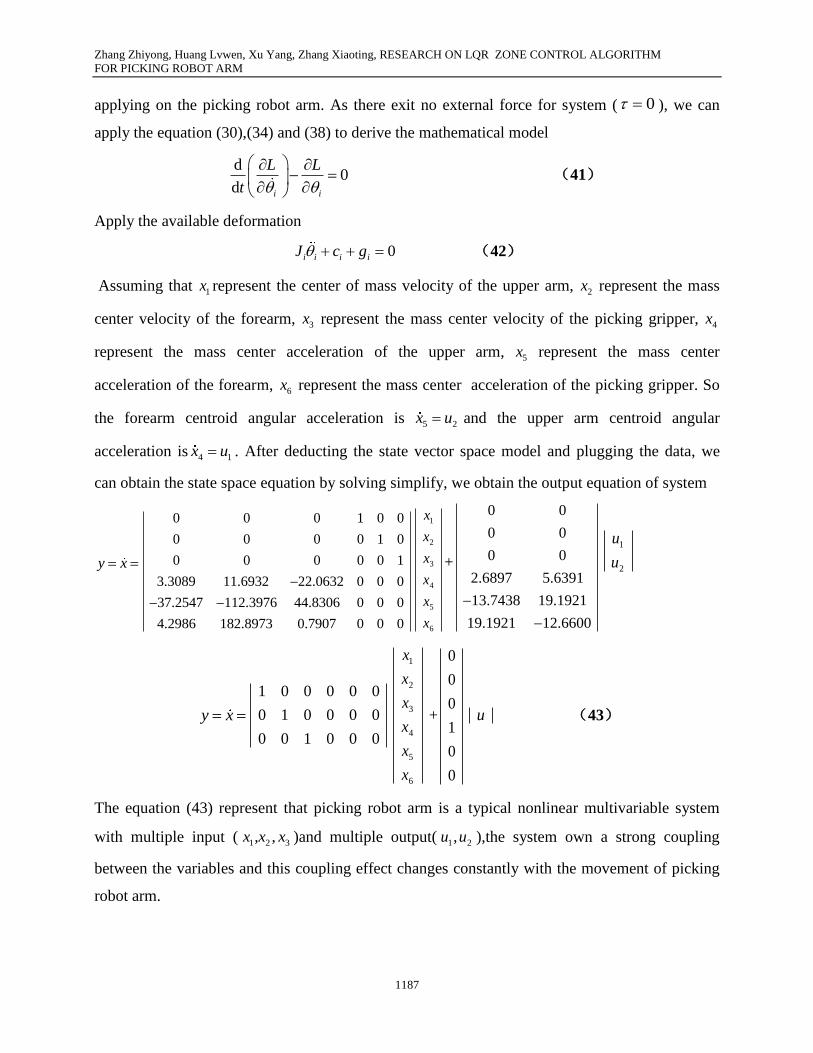
applying on the picking robot arm. As there exit no external force for system ( 0 ), we can
apply the equation (30),(34) and (38) to derive the mathematical model
d0
d i i
L L
t
(41)
Apply the available deformation
0i i i iJ c g (42)
Assuming that 1x represent the center of mass velocity of the upper arm, 2x represent the mass
center velocity of the forearm, 3x represent the mass center velocity of the picking gripper, 4x
represent the mass center acceleration of the upper arm, 5x represent the mass center
acceleration of the forearm, 6x represent the mass center acceleration of the picking gripper. So
the forearm centroid angular acceleration is 5 2x u and the upper arm centroid angular
acceleration is 4 1x u . After deducting the state vector space model and plugging the data, we
can obtain the state space equation by solving simplify, we obtain the output equation of system
y x
0 0 0 1 0 0
0 0 0 0 1 0
0 0 0 0 0 1
3.3089 11.6932 22.0632 0 0 0
37.2547 112.3976 44.8306 0 0 0
4.2986 182.8973 0.7907 0 0 0
1
2
3
4
5
6
x
x
x
x
x
x
+
0 0
0 0
0 0
2.6897 5.6391
13.7438 19.1921
19.1921 12.6600
1
2
u
u
y x
1 0 0 0 0 0
0 1 0 0 0 0
0 0 1 0 0 0
1
2
3
4
5
6
x
x
x
x
x
x
+
0
0
0
1
0
0
u (43)
The equation (43) represent that picking robot arm is a typical nonlinear multivariable system
with multiple input ( 1 2 3, ,x x x )and multiple output( 1 2,u u ),the system own a strong coupling
between the variables and this coupling effect changes constantly with the movement of picking
robot arm.
Zhang Zhiyong, Huang Lvwen, Xu Yang, Zhang Xiaoting, RESEARCH ON LQR ZONE CONTROL ALGORITHM
FOR PICKING ROBOT ARM
1188
III. DYNAMICS MODELING OF PICKING ROBOT ARM SPACE
The joints are the core component of space manipulator joints and they play an important role in
the mechanical arm dynamics. They can not only do plane motion but also can take complex
spatial motion in the joint space. The position X of 3 - DOF picking robot arm depends on the
three joint variables, and these joint variables are also called 3 d joint vector q. All of these joint
vectors q constitute the joint space. Picking robot arm assignments is finished in rectangular
coordinate space, namely, so we describe the joint position in the rectangular coordinate space
and we call this space as picking space. Kinematics equation ( )X X q is mapping form the joint
space to picking space, but the kinematics inverse solution come from the mapping in joint space.
In joint space and picking space, dynamics equations have different expression form, there exist
the certain corresponding relationship between the representations.
(1). Dynamic joint space equations
Understanding the dynamic characteristics of the joints accurately and comprehensively is the
key to correct analysis and simulation the movement characteristics of picking space, but
establishing accurate dynamic model of the joints is the basis on designing, analysis and
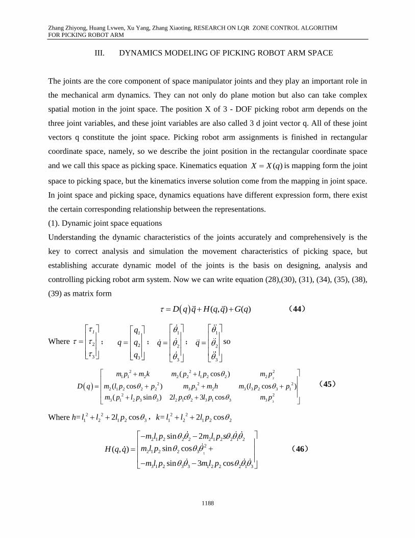
controlling picking robot arm system. Now we can write equation (28),(30), (31), (34), (35), (38),
(39) as matrix form
( , ) ( )D q q H q q G q (44)
Where
2
3
1
; 2
3
1q
q
;
1
2
3
q
;
1
2
3
q
so
2
3
2 2 2
1 1 2 2 2 1 2 2 2
2 2 2
2 1 2 2 2 3 3 2 3 3 2 3 1
2 2
3 1 2 3 3 2 1 2 3 1 3 3
( cos )
( cos ) ( cos )
( sin ) 2 3 cos
m p m k m p l p m p
D q m l p p m p m h m l p p
m p l p l p c l p m p
(45)
Where h=2 2
1 2 1 2 32 cosl l l p ,k=2 2
1 2 1 2 22 cosl l l p
1
2 1 2 2 2 2 1 2 2 1 2
2
2 1 2 2 3
3 1 2 3 3 1 2 2 2 1 3
sin 2
sin cos( , )
sin 3 cos
m l p m l p s
m l pH q q
m l p m l p
(46)
Zhang Zhiyong, Huang Lvwen, Xu Yang, Zhang Xiaoting, RESEARCH ON LQR ZONE CONTROL ALGORITHM
FOR PICKING ROBOT ARM
1189
1 1 2 1 1 2 2 3
3 1 2
2 2 3 2 2 2 2 3
( ) sin sin
sin
( ) sin 3 sin
m p m l g m p g
m p gG q
m p m l g m p g
(47)
Equation (44) is the general structure form of the dynamics equation in joint space, which
represents the relationship between the joint torque and joint variables, function velocity and
acceleration. In view of the picking robot arm own joints form, the ( )D q denotes n ×n positive
definite symmetric matrices, it is the inertia matrix, the ( , )H q q denotes n ×1 centrifugal force
and Coriolis force vector, the ( )G q denotes n ×1 gravity vector, it relates to the form q of picking
robot arm .
(2). Dynamic equations of picking space
Corresponding to the dynamics equation in the joint space, the dynamics equation of picking
robot arm in the Cartesian space can be represented by rectangular coordinate variables, namely,
the dynamics equation of picking robot arm in Cartesian space can be represented by position
vector X of picking grippers. To making full use of space dynamic, we can make picking gripper
to the expected position, trip, or to achieve a predetermined picking action, and can also get the
space predetermined trajectory. As mentioned above, the relationship between the picking force F
and picking gripper acceleration x can be represented as
( , ) ( )x x xF M q X U q q G q (48)
Where xM q X denotes the inertia matrix of picking space, ( , )xU q q denotes the centrifugal
force vector, Gx(q) denotes the Coriolis force vector, gravity vector, F denotes the generalized
picking force vector. The corresponding relationship between joint space dynamic equation and
picking space dynamics equation can be solved by the relationship between the generalized
picking force F and the generalized joint force and the relationship between the velocity and
acceleration of picking space and joint space
TJ q F (49)
( )
( ) ( )
X J q q
X J q q J q q
(50)
IV. LQR ZONE CONTROLLER DESIGN OF PICKING ROBOT ARM
Zhang Zhiyong, Huang Lvwen, Xu Yang, Zhang Xiaoting, RESEARCH ON LQR ZONE CONTROL ALGORITHM
FOR PICKING ROBOT ARM
1190
(1). Design on the picking Zone control
According to the dynamic model equation of apple picking robot arm and the above described
controlling strategy, the motion control space can be broken into two corresponding secondary
range, the stretching area which the main movement space including approaching the mature
apple position, the picking areas which main the movement space including picking mature apple
position. Because the stretching mechanism in the large range of motion in preparation for
fetching mature apple alike mankind stretching process, that is to say, first driving the upper arm
by the rotation shoulder, then driving the forearm by the elbow joint until picking gripper
stretching to grab area. In the whole picking action, the potential energy of picking forearm and
picking gripper increases gradually, when the picking gripper reach picking district, the shoulder
joint and elbow joint can reach into the servo steady state. From the energy increase in stretching
process and the picking robot arm control laws, the total energy in the process of movement is
3 3
1 1
, i i
i i
E K P
(51)
In order to ensure the energy increases in the whole stretching action, the following equation
must be established as
,E ≥0 (52)
By the characteristics of the ant symmetric matrix,
,E (53)
To meet the increasing energy inequality conditions, the control torque of stretching area is
sgni i iN (54)
Where sgn() denotes the symbolic function, iN denote the additional force, 0iN , i=2,3.
The basic idea of stretching control is that the system energy should be increased in the control
process. Actually, we could design controller for the shoulder joint drives and the wrist drives to
ensure the additional force decreases with the increase of energy and stretch smoothly to picking
area.
b. The LQR control of picking robot arm
In order to deal with the control system simply, the system equation will be discretized. The
common discretization methods including Euler method, linear differential complement, zero-
valet maintain, zero pole assignment and double linear differential complement [16-18]. As a
Zhang Zhiyong, Huang Lvwen, Xu Yang, Zhang Xiaoting, RESEARCH ON LQR ZONE CONTROL ALGORITHM
FOR PICKING ROBOT ARM
1191
kind of multivariable, coupling nonlinear system, Euler method is suitable for the nonlinear
systems with time-delay [19], so the control equation on accurate discretization is represented as
1x k Gx k Hu k
y k Gx k
(55)
Where exp( )G AT , 0
exp( ( )) dT
H A T B t , T denotes the sampling period of discretization,
k=0,1,2,….,n. The Linear Quadratic Regulator called LQR controller should judge whether if the
system is controlled firstly. Generally, we judge the controllability using the system
controllability matrix Mc=[H GH G5H]is full rank or not. If the controllability matrix is a full
rank, the system can be controlled, otherwise the system can be not controlled. By calculating we
know that Mc rank is 6, means the full rank matrix, it represents that the picking robot arm
system is controllable. In this system, we can achieve stability using configuring system poles
through state feedback variables( 1 2 3 1 2 3, , , , , )and gain the control strategy of linear
feedback controller shown as Figure 2.
Figure. 2 Linearity feedback controller strategy of the picking system
We can obtain the state feedback variables by the servo motor encoder, the encoder used for
measuring the angle and its own difference. According to the literature experience [19-20], we
can apply the classical effective control strategy directly the quadratic optimal control strategy
based on the linear model. So the state space model is applied to design the LQR controller in the
picking area. By the conclusion [21], we can gain the linear quadratic optimal control law, the
controller state equation is
( ) ( )u t Kx t (56)
Zhang Zhiyong, Huang Lvwen, Xu Yang, Zhang Xiaoting, RESEARCH ON LQR ZONE CONTROL ALGORITHM
FOR PICKING ROBOT ARM
1192
According to the simplified system state equation x Ax Bu from the equation (43), we can
obtain the value of k in the optimal control vector matrix ( ) ( )u t Kx t which makes the
performance index J is minimal.
0( ' ' )dJ x Qx u Ru t
(57)
Where Q denotes positive definite or positive semi-definite Hermitical and real symmetric matrix,
R denotes positive definite Hermitical or real symmetric matrix. Matrix Q and R determine the
relative weighting factor of the error and the energy loss, we can solve the best stability control
problem of picking robot arm by substituting the equation (56) into the simplified equation of
state
( )x Ax BKx A BK x (58)
In the derivation equation, it is assumed that A BK matrix is stable, that is to say, all the
characteristic roots of A BK have negative real part or on the left half complex plane, substitute
equation (56) into the equation (57)
0 0( ' ' ' )d ' + ' ) dJ x Qx x K RKx t x Q K RK x t
( (59)
According to the parameter optimal problem [20-21]
' + ' ) ( ' )d
x Q K RK x x Pxdt
( (60)
The P in the equation (60) is the Hermitical positive definite and symmetric matrix. So
' + ' ) ' ' '[( ) ' ( )]x Q K RK x x Px x Px x A BK P P A BK x ( (61)
Comparing on both side of equation ( 61) and known that equation is established for any x, so
( ) ' ( ) ( ' )A BK P P A BK Q K RK (62)
According to the Lyapunov second order method [22],if A BK is a stable matrix, there must
exist a positive definite matrix satisfying the equation (62). Determining the element of P and
testing whether the positive definite by this method, if the picking robot arm system is stable, we
can always seek a positive definite matrix P satisfy the equation and solve the equation. the
performance index of equation (59) can be calculated as
00( ' ' ' )d ' '( ) '(0) (0)J x Qx x K RKx t x Px x Px x Px
(63)
Because of all the characteristic roots of A BK own negative real part, so ( ) 0x
Zhang Zhiyong, Huang Lvwen, Xu Yang, Zhang Xiaoting, RESEARCH ON LQR ZONE CONTROL ALGORITHM
FOR PICKING ROBOT ARM
1193
'(0) (0)J x Px (64)
So the performance indicators can be obtained according to the initial conditions (0)x and the
matrix P.
We can solve the solution of quadratic optimal control problem by certain steps. Because the
matrix A is a positive definite Hermitical or symmetric matrix, it can be represented n as 'R T T ,
the matrix T is not a singular matrix. The equation (62) can be represented as
( ' ' ') ( ) ( ' ' ) 0A B K P P A BK Q K T TK (65)
We need to calculate the minimum of J to K, namely the minimum of 1'[ ( ') ' ]'x TK T B P
1[ ( ') ' ]TK T B P x to K, for the result of this equation is not negative, it can search the minimum
when it is zero, namely, it can gain the minimum when the equation 1( ') 'TK T B P is found. so
1 1 1( ') ' 'K T T B P R B P (66)
equation (66) give the best matrix K, so when the performance of the quadratic optimal control
problem is defined by equation (57), the optimal control law is linear and we can obtain it from
1( ) ( ) ' ( )u t Kx t R B Px t . The equation (66) must satisfy the following degradation equation
1' ' 0A P PA PBR B P Q (67)
The equation (67) is called the degenerate matrix rickety equation, its design steps is included
that first solving the degradation of rickety equation to obtain the matrix is P, if there is the
positive definite matrix P, the system is stable, namely, the matrix A BK is stable, then we can
obtain the best matrix K by generating the matrix into the equation (66).
V. THE SIMULATION EXPRIMENTS AND ANALYSIS
(1). Experimental methods and steps
a. Establish relation curve s of kinematics mathematic model
Firstly, with the aid of the necessary translational and rotational movement, we can make the
base coordinate system superposes with the fixed coordinate system and establish the
correspondence relationship between the measurement data and motion equations, Then gain the
picking space coordinates of picking grippers such as 8A (-900,492,-871) shown as table 2 and
substitute the coordinate values into the equation (49) and (50),we can obtain the positions of
Zhang Zhiyong, Huang Lvwen, Xu Yang, Zhang Xiaoting, RESEARCH ON LQR ZONE CONTROL ALGORITHM
FOR PICKING ROBOT ARM
1194
picking robot arm joints, then set the displacement drive of joint using a STEUP function and set
5s simulation time and 50 simulation steps and writing Matlab program to observe the movement
simulation for picking robot arm ,we can gain the relation curves of kinematics mathematical
model shown in figure 3, figure 4, figure 5 to the simulation.
(2) Establish unit step response curve in picking area
We can solve continuous time of linear quadratic controlling problem make use of the Matlab
command [K,P,E]=LQR(A,B,Q,R), and can also solve the related rickety equation, This
command is applicable to calculate the optimal feedback gain matrix K, and produce performance
metrics and make it to tiny feedback control law on the condition of constraint equation
x Ax Bu . In order to meet the requirements of stability control,the corresponding weight
coefficient of the controlled variables and the weight values matrix is generally larger, and only
when the weight values matrix is generally larger, the system can quickly achieve a stable state to
suppress the fluttering. The value of the matrix Q in a certain range is larger, the time to regulate
the system is shorter, but it is not too large, while enlarge to a certain extent it can lead to larger
fluttering and be not conducive to stable. Because the angular velocity of joint has bigger
influence on the control system, the value of the matrix Q and R is the following
100 0 0 0 0 0
0 100 0 0 0 0
0 0 110 0 0 0
0 0 0 100 0 0
0 0 0 0 100 0
0 0 0 0 0 100
Q
20 0
0 20R
Make use of the value of the matrix Q and R, we can solve the optimal state feedback matrix,
then we can solve the optimal state feedback gain matrix LQRK =[31.1208 -18.171 3.2670 4.2683
-2.6939 -7.0642 ] according to the A and B in the equation (43) and the known testing parameter
data after we choose the weight matrix. Then we can validate the unit step response of the

Zhang Zhiyong, Huang Lvwen, Xu Yang, Zhang Xiaoting, RESEARCH ON LQR ZONE CONTROL ALGORITHM
FOR PICKING ROBOT ARM
1195
designed LQR controller using the Matlab program shown as Figure 4.
Figure.3 The relationship between picking force and joints force
Figure. 4 The curve of joint velocity between picking space and joint space
Figure.5The curve of joint acceleration between picking space and joint space
Zhang Zhiyong, Huang Lvwen, Xu Yang, Zhang Xiaoting, RESEARCH ON LQR ZONE CONTROL ALGORITHM
FOR PICKING ROBOT ARM
1196
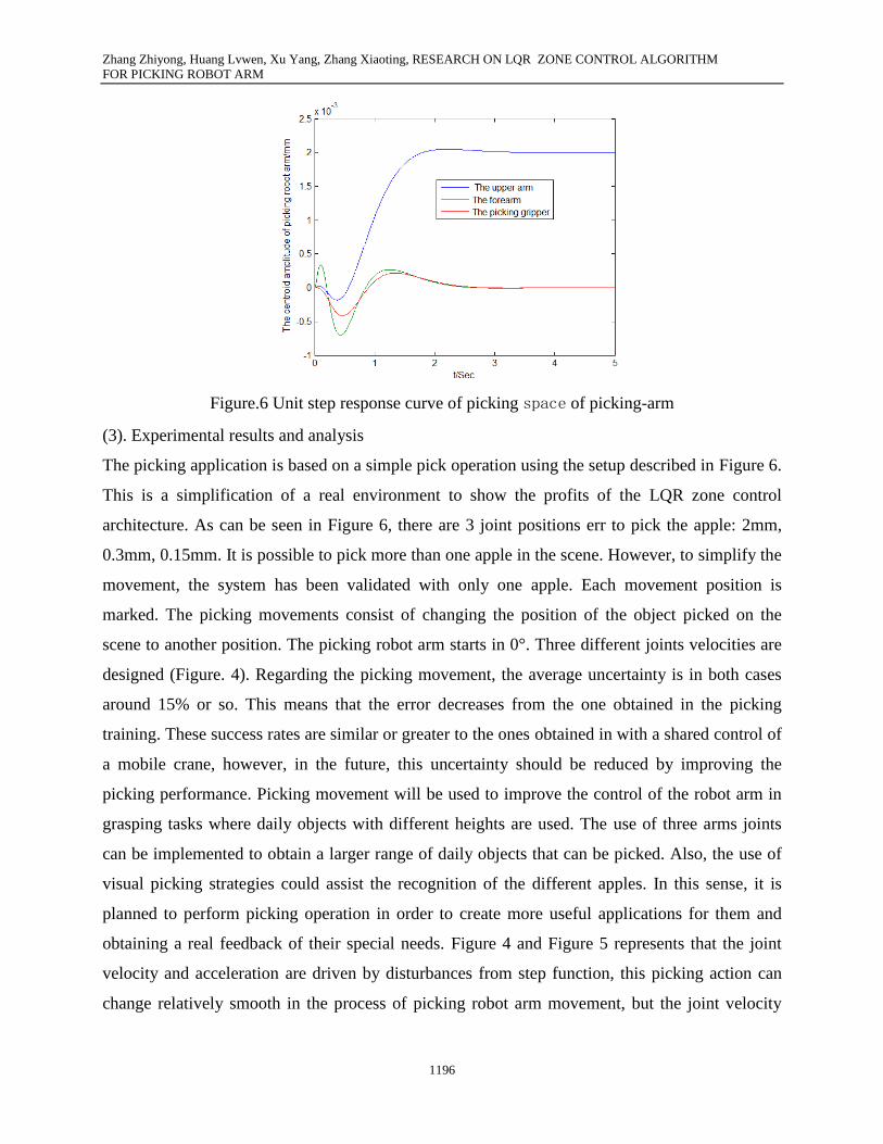
Figure.6 Unit step response curve of picking space of picking-arm
(3). Experimental results and analysis
The picking application is based on a simple pick operation using the setup described in Figure 6.
This is a simplification of a real environment to show the profits of the LQR zone control
architecture. As can be seen in Figure 6, there are 3 joint positions err to pick the apple: 2mm,
0.3mm, 0.15mm. It is possible to pick more than one apple in the scene. However, to simplify the
movement, the system has been validated with only one apple. Each movement position is
marked. The picking movements consist of changing the position of the object picked on the
scene to another position. The picking robot arm starts in 0°. Three different joints velocities are
designed (Figure. 4). Regarding the picking movement, the average uncertainty is in both cases
around 15% or so. This means that the error decreases from the one obtained in the picking
training. These success rates are similar or greater to the ones obtained in with a shared control of
a mobile crane, however, in the future, this uncertainty should be reduced by improving the
picking performance. Picking movement will be used to improve the control of the robot arm in
grasping tasks where daily objects with different heights are used. The use of three arms joints
can be implemented to obtain a larger range of daily objects that can be picked. Also, the use of
visual picking strategies could assist the recognition of the different apples. In this sense, it is
planned to perform picking operation in order to create more useful applications for them and
obtaining a real feedback of their special needs. Figure 4 and Figure 5 represents that the joint
velocity and acceleration are driven by disturbances from step function, this picking action can
change relatively smooth in the process of picking robot arm movement, but the joint velocity

Zhang Zhiyong, Huang Lvwen, Xu Yang, Zhang Xiaoting, RESEARCH ON LQR ZONE CONTROL ALGORITHM
FOR PICKING ROBOT ARM
1197
and acceleration appear to sudden change nearby the 2s and 3s. In order to reduce the instability
in the process of the picking robot arm movement, we should correct the centrifugal force, the
Coriolis force vector and gravity vector to reduce driving joints in turn and to enhance the overall
operation stability. Figure 3 represents that joint force and picking force curve can change
without mutation in the case of external environment. It also represents that picking robot arm
can move smoothly and have no vibration in the process of picking movement. By comparing
picking robot arm joint force curve, we can gain the shoulder joint torque is the largest, so on the
beginning of picking robot arm , the longest shoulder joint is, the biggest force providing. Elbow
and wrist joints are the second. Simulation results represent the correctness to the kinematics
equation in picking space. After correcting the centrifugal force, Coriolis force vector and gravity
vector, we can gain the result from the unit step response curve of the picking area shown as
Figure 6, the most vibration quantity of upper arm is about 4.6 mm, the fitting time for forearm is
less than 2s, As for the end actuator picking grippers, the vibration quantity is the minimum
through the same direction vibration as the forearm approximately, it can tend to be stable in
about 1.5s, Three joints eliminated vibration in the picking space and reached the basic stability
state in 2s or so with the smaller vibration quantity less than 4.6 mm.
VI. CONCLUSIONS
This paper is dedicated to solve the poor stability of picking robot arm in picking apples and
reduce the fluttering problems. A novel robust LQR zone control algorithm featuring finite-time
parameter estimation for humanoid robot arm is presented. The picking feature introduced both in
the picking and estimation scheme provides two-fold benefits. One is to provide significant levels
of robustness against bounded disturbance both within the picking error and estimation error. The
second benefit is that finite-time convergence in the parameter estimation error can be guaranteed
given sufficient instability condition in the picking movement. According to the design of energy
zone controller based on LQR and the simulation, the upper arm, forearm and picking grippers
can reach the stability state in the interval of 2s or so, when there exit input disturbance. The
overshoot amount is the relatively small and the system has the strong robust stability and level
off quickly. Moreover, we establish the analysis and research on the robust performance by the
LQR algorithm energy zone strategy to ensure the reliability of the control strategy.
Zhang Zhiyong, Huang Lvwen, Xu Yang, Zhang Xiaoting, RESEARCH ON LQR ZONE CONTROL ALGORITHM
FOR PICKING ROBOT ARM
1198
Acknowledgements
This work is funded by Technology Innovation Foundation of Northwest A&F University
(No.QN 2013051 and No.2014Yb068) and Doctor Scientific Research Startup Project
(No.2013BSJJ106).
REFERENCES
[1] I. Payo, V. Feliu, O.D. Cortazar, “Force control of a very lightweight single-link flexible arm
based on coupling torque feedback”, Mechatronics Vol.19 ,2009,pp.334–347.
[2] M. Madani, M. Madani, M. Moallem, “Hybrid position/force control of a flexible parallel
manipulator”, Vol.348, 2011, pp.999–1012.
[3] Chen C., Ong S., Nee A., Zhou Y, “Haptic-based interactive path planning for a virtual robot
arm”, International Journal on Interactive Design and Manufacturing,Vol.4,no.2, 2010,pp. 113-
123
[4] Alessandro Shimabukuro,“No deal in space: A bargaining model analysis of U.S. resistance
to space arms control”, Space Policy,Vol.30,2014, pp.13-22
[5] Damianou C, Ioannides K, Milonas N, “Positioning device for MRI-guided high intensity
focused ultrasound system”, International Journal of Computer Assisted Radiology and Surgery,
Vol.2,no.6, 2008,pp. 335-344
[6] Decker M D R, Dreier T, Fischer M, Gutmann M, Ott I, Spiecker G D, “Service robotics: do
you know your new companion? Framing an interdisciplinary technology assessment”, Poiesis &
Praxis: International Journal of Technology Assessment and Ethics of Science. Vol.8,no.1,
2011,pp. 25-44
[7] Efe M, “ADALINE based robust control in robotics: a Riemann-Liouville fractional differ
integration based learning scheme”, Soft Computing - A Fusion of Foundations, Methodologies
and Applications. Vol.13,no.1, 2009,pp. 23-32
[8] M.N. Mahyuddin, S.G. Khan, G. Herrmann,“A novel robust adaptive control algorithm with
finite-time online parameter estimation of a humanoid robot arm”, Robotics and Autonomous
Systems,Vol.62 ,2014,pp.294–305
Zhang Zhiyong, Huang Lvwen, Xu Yang, Zhang Xiaoting, RESEARCH ON LQR ZONE CONTROL ALGORITHM
FOR PICKING ROBOT ARM
1199
[9] Feng J., Gao F., Zhao X., Yue Y., Liu R,“ A new macro-micro dual drive parallel robot for
chromosome dissection”, Journal of mechanical science and technology, Vol.26,no.1, 2012,pp.
187-194
[10 ]Fujioka K., Geis P., Saito M., Matsuoka H., “Visualization of yeast single-cells on fabric
surface with a fluorescent glucose and their isolation for culture, Journal of industrial
microbiology \& biotechnology”, Vol.34,no.10, 2007,pp. 685-688
[11] Hagras H, Colley Mn, Callaghan V, Carr-West M, “Online Learning and Adaptation of
Autonomous Mobile Robots for Sustainable Agriculture, Autonomous Robots”, Vol.13,no.1,
2002,pp. 37-52
[12] Takahiro Endo, Haruhisa Kawasaki,“Bending moment-based force control offlexible arm
under gravity”, Mechanism and Machine Theory,Vol.79,2014,pp.217–229
[13] Harper C., Virk G, “ Towards the Development of International Safety Standards for Human
Robot Interaction, International Journal of Social Robotics, Vol.2,no.3, 2010,pp. 229-234
[14] He B, Liu G, Ji Y, Si Y S, Gao R,“Auto Recognition of Navigation Path for Harvest Robot
Based on Machine Vision”, Springer Boston, 2011,pp.138-147
[15] Katharina Beier*,Detlef Ehlert,“Methods for evaluation of picking performance of
chamomile (Matricaria recutita L.) harvesters. Part I:Comparison of established methods”
Journal of Applied Research on Medicinal and Aromatic Plants,Vol.1,2014,pp.e1–e7
[16] Lee S Lee Y, Park B, Lee S, Han C, “ MFR (Multipurpose Field Robot) for installing
construction materials, Autonomous Robots”, Vol.22,no.3, 2007,pp. 265-275
[17] Lee T, Hudson S, Chang J Y, “Auto-detection micro-controller-based autonomous band
wrapping system for targeted pest control”, Microsystem Technologies, Vol.16,no.1, 2010,pp.
227-238.
[18] G. Sen Gupta and S.C. Mukhopadhyay, “A Triangular Targetting Algorithm (TTA) for
Motion Control of Wheeled Mobile Robots”, Proceedings of the International Conference on
Emerging Mechanical Technology – Macro to Nano (EMTM2N 20007), February 16-18, 2007 at
Pilani, India, pp. 204-209.
[19] Monta M., Kondo N. and Ting K.C,“ End-Effectors for Tomato Harvesting Robot, Artificial
Intelligence Review”, Vol.12,no.1, 1998,pp.11-25.

Zhang Zhiyong, Huang Lvwen, Xu Yang, Zhang Xiaoting, RESEARCH ON LQR ZONE CONTROL ALGORITHM
FOR PICKING ROBOT ARM
1200
[20] S.C.Mukhopadhyay and G. Sen Gupta, “Sensors and Robotic Environment for Care of the
Elderly”, Proceedings of IEEE International Workshop on Robotic and Sensors Environments,
Ottawa, Canada, 12-13, 2007, pp. 68-73.
[21] Naveen K, Jin-Hwan B, Vikas Pand J C,“Tracking control of redundant robot manipulators
using RBF neural network and an adaptive bound on disturbances, International Journal of
Precision Engineering and Manufacturing”, Vol.13,no.8, 2012,pp.1377-1386.
[22] G. Sen Gupta, S.C.Mukhopadhyay and J. R. French, Wireless Communications and Control
Module of a Web-Enabled Robot for Distributed Sensing Applications, Proceedings of IEEE
International Instrumentation and Measurement Technology Conference, Victoria, Canada, May
12-15, 2008, pp. 393-398.
[23] Andrés Úbeda, Eduardo Iáñez∗, José M. Azorín,“Shared control architecture based on RFID
to control a robot arm using a spontaneous brain–machine interface”, Robotics and Autonomous
Systems, Vol.61,2013,pp.768–774.
[24] František Kumhála,Miroslav Kavka, Václav Prošek,“Capacitive throughput unit applied to
stationary hop picking machine”, Computers and Electronics in Agriculture,Vol.95,2013,pp.92–
97.
[25] G. Sen Gupta, S.C. Mukhopadhyay, S. Demidenko and C.H. Messom, “Master-slave
Control of a Teleoperated Anthropomorphic Robotic Arm with Gripping Force Sensing”, IEEE
Transactions on Instrumentation and Measurement, Vol. 55, No. 6, pp. 2136-2145, December
2006.
[26] McCarthy C. L, Hancock N. H and Raine S. R, “Applied machine vision of plants: a review
with implications for field deployment in automated farming operations”, Intelligent Service
Robotics, Vol.3,no.4, 2010,pp. 209-217