Embed Size (px)
Citation preview

Research on EMAT Excitation Based on RLC Oscillator
Zhiyu Li, Peng Chen, Shuai Wang, Aihua Xu Ordnance Engineering College of PLA, Shi Jiazhuang, China
e-mail [email protected]
Abstract: The paper mainly researches a new method of EMAT (Elector-magnetic Acoustic Transducer) ex-citation-continuously pulse excited electro-magnetic ultrasonic. Its aim is improving magnetic-sound trans-form efficiency of EMAT. It solves some problems such as low sensitivity and blight of thermal affection. Based on the basis model of EMAT, it uses IGBT, a new kind of switch power supply, instead of AC contac-tor. It realizes auto-excitation of EMAT, and accomplishes charge and discharge capacitance automatically. It introduces fundamental of EMAT, and dynamic analyze how to choose the parameters of RLC pulse circuit plus IGBT. The whole circuit is researched through the way of experiment. Then it acquires ideal projects of arranging elements’ parameters. In the end, the paper acquires unite conclusion of theory analysis and ex-periment.
Keywords: EMAT; IGBT; RLC oscillation
1 Introduction
EMAT is short for Electro-Magnetic Acoustic Transducer.
It’s a new device for acoustic emission and receiving. It
has many advantages such as noncontact the material be-
ing tested directly in process of testing. It doesn’t need
couple agent, has high speed testing and good repeatabil-
ity, and performs well at high temperature, and is suitable
to test material with special shape, and so on. So the
EMAT has taken more and more attention of people in
the field of Nondestructive-Testing. The traditional
method for producing EMAT excitation is that signal
source makes pulse signals, and power is amplified, and
then is transmitted to coil as excitation. There are some
problems in this method, such as power is consumed too
much when current is amplified. And intensity of acoustic
signals could be affected because of hot bearing capacity
of coil. So the paper puts forward using the way of ca-
pacitance discharges in the RLC oscillating circuit to
produce strong current pulse as coil excitation. This
method has many advantages such as concentrating
power, high instantaneous current peak and low heat. It is
propitious to improve ultrasonic signals intensity.
2 Basic Principle o f Electro-Magnetic Ultras- onic
Generally, EMAT includes 3 parts: ①coil; ②magnet; ③
work piece. The basic principle is: The eddy current will
be induced in the surface of the work when there is a coil
near it; the coil is accompanied with high frequency alter-
native current. At the same time, make it in a directional
magnetic field. So the eddy current and the magnetic field
can interact each other to generate Lorentz force. This
force will act on crystal lattice; the folium of the material
is under the reciprocating force. Finally, the ultrasound is
generated. The inverse process of this is the principle of
electromagnetic ultrasonic receiving. For different materi-
als, the force source is not only Lorentz force, but also it
includes magnet astrictive effect.
3 Choosing Circuit Parameter Theoretically
Analyzing RLC circuit which is shown in figure 1, and
acquiring ideal signals as excitation of pulse elec-
tro-magnetic ultrasonic, it should choose reasonable circuit
parameter to make RLC discharge circuit work in under-
damp. Frequency of signals is higher than 20kHz. The
peak signal must be as high as possible. The attenuation
should not be too fast. As follows, it discusses the relation
among parameters in “under damped” producing alternat-
ing signals.
Figure 1. RLC discharging circuit
849
Proceedings of 14th Youth Conference on Communication
978-1-935068-01-3 © 2009 SciRes.

3.1 Total Resistance in the Circuit
The total resistance in the circuit should fulfill the for-
mula 2R L C ; considering attenuation modulus :
2R L .Because the larger is, the more
quickly attenuate, to ensure the excitation of pulse
electro-magnetic ultrasonic has durative, the total resis-
tance should be as small as possible. It can make attenua-
tion of signals not too fast.
( )CU t
3.1.1 Considering the Signal Frequency f The formula
2
2
11 4
2 2d
R
LC LfT
()
shows inverse ratio between frequency f and resis-
tance . Because exciting ultrasonic signals in the end,
the frequency of stimulating signals should be higher than
20kHz. must be small enough to ensure kHz.
R
R 20f
3.1.2 Considering current peak miThe formula
2
2
0 2
2
2 12exp( )
14
m
R L Rarctg
C 4L R LC Li UL R
LC L
()
shows decreasing can increase . Considering conver-
sation of energy, capacitance power storage is , induc-
tance power storage is
R mi
CW
LW , from beginning of discharge
to current peak, the Active Power Loss is RW . The rela-
tion of the three is
C LW W W R
Namely
2 2 2 20 0
1 1 1
2 2 2
mt
m mCU CU Li i Rdt .
In the formula, is the voltage of capacitance when
is peak. So it shows must be decreased as much as
possible so that the active power loss is decreased and
is increased.
mU
mi
mi
R
3.2 Inductor value L
3.2.1 Considering attenuation modulus
The formula2
R
L shows increasing inductor value L
properly can decrease , and delay the attenuation of the signals.
3.2.2 Considering current peak mi
The formula 0d
m
Ci U e
L
shows the change of L will
affect much. So decreasing L is helpful to increasing
current peak. mi
Considering apparent wave-head time of discharge cur-
rent (raising time of pulse current from zero to 90% peak).
Accompany with the increase of L, discharge current ap-
parent wave-head time is delayed. Because when
t=0, maximum rising rate of pulse current is 0( )M
Udi
dt L .
So the bigger L is, the smaller maximum rising rate is.
3.3 Capacitance value C
3.3.1 Considering signal frequency f
According to (2), it’s inverse ratio between capacitance
value C and frequency . So reducing C can ensure signal
frequency kHz.
f
20f 3.3.2 Considering current peak mi
According to (1), increasing can increase . C mi
3.4 Initial value of capacitance voltage 0U
According to (1), it shows direct ratio between and ,
so it must increase as much as possible. 0U mi
0U
Considering apparent wave-head time of discharge current, Increasing can raise maximum rising rate of
pulse current. So it decreases the time, and makes wave-head steeper.
0U
Sum up the upper theories, to acquire ideal excitation signals, parameter should be chosen as follows:
① should be small ② should be moderate ③
should be moderate ④ should be large. R L
C 0U
4 Choosing Circuit P arameter Experimen-tally
4.1 Analyzing RLC Pulse Discharging Current
A kind of switch power-IGBT is used in the experiment
as an electronic switch for conduction and shutdown. The
paper uses multivibrator and monostable trigger to control
IGBT. The figure of time series is showed in figure 2. Its
working steps are as follows: figure 3 is a sketch map of
the current. At t=0, IGBT1 conducts, and then high volt-
age DC power supply charge up the capacitance, and cal-
culate the charge time t1. The dropping edge of multivi-
brator makes monostable trigger 1 work, which is delay-
ing the whole process, called t2. The falling edge makes
850
Proceedings of 14th Youth Conference on Communication
978-1-935068-01-3 © 2009 SciRes.
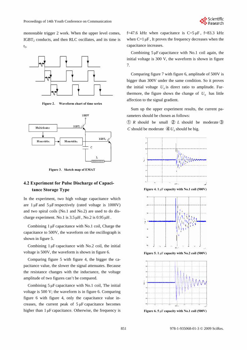
monostable trigger 2 work. When the upper level comes,
IGBT2 conducts, and then RLC oscillates, and its time is
t3.
Figure 2. Waveform chart of time series
Figure 3.Sketch map of EMAT
4.2 Experiment for Pulse Discharge of Capaci-tance Storage Type
In the experiment, two high voltage capacitance which
are 1 and 5 respectively (rated voltage is 1000V)
and two spiral coils (No.1 and No.2) are used to do dis-
charge experiment. No.1 is 3.5 , No.2 is 0.95 .
μF μF
μH μH
Combining 1 capacitance with No.1 coil, Charge the
capacitance to 500V, the waveform on the oscillograph is
shown in figure 5.
μF
Combining 1μ capacitance with No.2 coil, the initial
voltage is 500V, the waveform is shown in figure 6.
F
Comparing figure 5 with figure 4, the bigger the ca-
pacitance value, the slower the signal attenuates. Because
the resistance changes with the inductance, the voltage
amplitude of two figures can’t be compared.
Combining 5 capacitance with No.1 coil, The initial
voltage is 500 V; the waveform is in figure 6. Comparing
figure 6 with figure 4, only the capacitance value in-
creases, the current peak of 5 capacitance becomes
higher than 1μ capacitance. Otherwise, the frequency is
f=47.6 kHz when capacitance is C=5 , f=83.3 kHz
when C=1 , It proves the frequency decreases when the
capacitance increases.
μF
F
μF
μF
μF
Combining 5μ capacitance with No.1 coil again, the
initial voltage is 300 V, the waveform is shown in figure
7.
F
Comparing figure 7 with figure 6, amplitude of 500V is
bigger than 300V under the same condition. So it proves
the initial voltage is direct ratio to amplitude. Fur-
thermore, the figure shows the change of has little
affection to the signal gradient.
0U
0U
Sum up the upper experiment results, the current pa-
rameters should be chosen as follows:
① should be small ② should be moderate ③
should be moderate ④ should be big.
R L
C 0U
Figure 4. 1 capacity with No.1 coil (500V) μF
Figure 5. 1 capacity with No.2 coil (500V) μF
Figure 6. 5 capacity with No.1 coil (500V) μF
851
Proceedings of 14th Youth Conference on Communication
978-1-935068-01-3 © 2009 SciRes.

References [1] WANG Shujuan; KANG Lei; ZHAO Zaixin et al, Overview of
Research Advances in Electromagnetic Acoustic Transducer[J]. Instrument Technique and Sensor, 2006,5: 47~50.
[2] ZHANG Zhigang, QUE Pei-wen, LEI Huaming. Design and realization of an Bi-Mode electromagnetic acoustic transducer inspection system with SH-plate waves and Lamb waves[J]. Industrial Instrumentation & Automation. 2005, (5):22~24.
[3] ZHANG Xiao_chun, LIU Chun_sheng, LI Hai_bao. Electromagnetism ultrasonic nondestructive technology and its application. Coal Mine Machinery. 2002, (2):69~70.
Figure 7. 5 capacity with No.1 coil (300V) μF [4] LIU Ji, HE Yuanji, YANG Jiaxiang. Numerical Analysis on Pulsed Capacitive Energy-stored Circuit with High Current[J]. JOURNAL OF HARBIN UNIVERSITY OF SCIENCE AND TECHNOLOGY. 1999, 4(5):90~94.
5 Choosing Circuit P arameter Experimen-tally [5] Xie Zurong Zhou Xiaozheng Zeng Jiantang Zhan Yongli. Study
on Pulse Magnetization Technique and Device[J]. Journal of Beijing Institufe of Petrochemical Technology. 2001, 9(1):51~54. The paper analyzes working process of RLC pulse dis-
charge current in theory and researches underdamped
instance deeply, and acquires choosing parameters pro-
jects through experimentation. In the end, the conclusion
of pulse discharge experiment is the same with theory.
[6] I SMITH. Pulsed Power in the United States: Digest of Technical Papers[C]. The 8th IEEE int. Pulsed Power Conf USA. 1991: 15~22.
[7] DU Tao. Simulation Analysis of Pulse Discharge Circuit[J]. Journal of Detection & Control. 2004, 26(3):42~45.
[8] SHEN Gong-tian; ZHANG Wan-ling. A review of Nondestructive Testing Techniques for Pressure Vessels [J]. Nondestructive Testing. 2004, 26(1):37~39.
852
Proceedings of 14th Youth Conference on Communication
978-1-935068-01-3 © 2009 SciRes.
![Retriggerable Monostable Multivibrators€¦ · Retriggerable Monostable Multivibrators Author: Texas Instruments, Incorporated [SDLS043,*] Subject: Data Sheet Keywords: SDLS043 Created](https://img.pdfslide.us/doc/110x75/605c572698fa48206917a2eb/retriggerable-monostable-multivibrators-retriggerable-monostable-multivibrators.jpg)