Embed Size (px)
Citation preview

International Journal of Advanced Robotic Systems, Vol. 7, No. 3 (2010) ISSN 1729-8806, pp. 227-238
227
Research of the Localization of Restaurant Service Robot Yu Qing-xiao, Yuan Can, Fu Zhuang and Zhao Yan-zheng Research Institute of Robotics, School of Mechanical Engineering, Shanghai Jiao Tong University, 800 Dongchuan road, Shanghai 200240, P.R. of China Corresponding author E-mail: [email protected] Abstract: This paper designs a restaurant service robot which could be applicable to providing basic service, such as ordering, fetching and sending food, settlement and so on, for the customers in the robot restaurant. In this study, both three landmarks positioning and landmark-based localization algorithms are proposed to localize the mobile robot with rough precision in the restaurant. And Optical Character Recognition (OCR) technology is used to distinguish the unique table number of different landmarks. When the high localization precision must be granted around the pantry table, the RFID-based localization algorithm is proposed to localize the mobile robot.Various experiments show that the proposed algorithms could estimate the robot pose reasonably well and could accurately evaluate the localization performance. Finally, the proposed service robot could realize real-time self-localization in the restaurant. Keywords: service robot; landmark; localization; OCR; RFID
1. Introduction
Mobile robot localization and object pose estimation in a working environment have been central research activities in mobile robotics. Solution of the mobile robot localization problem requires addressing of two main problems (R.Siegwart et al., 2004): the robot must have a representation of the environment; the robot must have a representation of its belief regarding its pose in this environment. Sensors are the basis of addressing the both problems. Many of the sensors available to mobile robots are introduced in (R.Siegwart et al., 2004), giving their basic principles and performance limitations. Based on this introduction, ultrasonic sensors (J.Leonard et al., 1991), goniometers (P.Bonnifait et al.., 1998), laser range finders (A.Arsenio et al., 1998), and CCD cameras (Y.Yamamoto et al., 2005) are sensors which are commonly applied in mobile robot localization projects to gather information on the robot's pose estimation at high precision. In the project, we mainly use binocular stereo camera and RFID sensors to gather enough information to realize self-localization and self-navigation. Vision systems are passive and of high resolution, and are the most promising sensors for future generations of mobile robots. Therefore, localization using vision sensors has drawn much attention in recent years. The data provided by a single camera is essentially 2D, but using stereo camera or monocular image sequences, full 3D information can be reconstructed. Many researches have been studied with regard to the application of stereo vision or image sequences. For example, a vision-based mobile robot localization and mapping algorithm which uses STIF (scale-invariant image feature) is applied for
mobile robot localization and map building in (J.Borenstein et al., 1996). Construction of 3D models from images, in the context of mobile robots exploring real indoor environments, is a thoroughly investigated topic in computer vision (Segueira et al., 1999; Levvia et al., 2001; Biber et al., 2004). G. Cicirelli uses the image from the camera to construct 3D models in order to enable the robot to navigate autonomously in indoor environments (G.Cicirelli, et al., 2006). Beata and Eris Chinellato uses stereo images and biologically inspired algorithms to accurately estimate pose, size and shape to grasp the target object (G.Beata et al., 2009). An RFID (Radio Frequency Identification) technology is a non-touch recognition system that transmits and processes the information on events and environments using a wireless frequency and small chips (Hahnel et al., 2004). With the popularity of indoor location sensing systems and more globally of research on positioning in wireless networks, RFID positioning issue has begun to emerge (Cangialosi et al., 2007). RFID has some desirable features, such as contactless communications, high data rate and security, non line-of-sight readability, compactness and low cost (Kentaro Yamano et al., 2004). This technology plays a key role in pervasive networks and services (Want, 2006). An RFID device typically consists of RF tags, a reader with one or more antennas and software to process the tag readings (Finkenzeller, 2003). The reader interrogates the tags, receiving their ID code and other information stored in their memory. Tags can be either passive or active. Passive tags are activated by the electromagnetic field generated by the RFID antenna. The passive RFID technology has been utilized for the research to recognize the position of the service
International Journal of Advanced Robotic Systems, Vol. 7, No. 3 (2010)
228
robot (Kentaro et al., 2004). There is a method that RFID passive tags are arranged on the floor to provide the absolute positions, which are free from the problems of conventional systems (Ohno et al., 2003; Komoriya et al., 1994). The absolute coordinates of the robot can be obtained robustly, with the RFID tag and reader in sensor network space (Lee et al., 2003; Shenoy et al., 2005) where sensors are properly embedded several places to provide the absolute position information to the service robot. And G.Michael uses the occlusion-free radio-frequency identification (RFID) transponder barriers to discriminate the different topological areas in order to realize the self-navigation (G.Michael et al., 2009). Since localization is a fundamental problem in mobile robotics, many methods have been developed and discussed in the literature. These approaches can be broadly classified into three major types: metric, topological and hybrid. Metric approaches (M. Dissanayake et al., 2001, A.Castellanos et al., 1999, S. Thrun, 2000) are useful when it is necessary for the robot to know its localization accurately in terms of metric coordinates. And, the state of the robot can also be represented in a more qualitative manner, by using a topological map (H.Choset et al., 2001, A.Tapus et al., 2006, P.Beeson et al., 2005). But these methods are also faced with some difficulties when the environments are changed. In this point of view, landmark-based methods are simple and powerful for accurate self-localization. Landmarks are divided into two classes: natural and artificial. In the methods using natural landmarks, robust extraction of natural landmarks have received considerable attention. Feature based approaches (A.Levin et al., 2004, S.Se et al., 2002, S.Se et al., 2005, R.Hartley et al., 2005) use natural landmarks in the environment, perform matching between landmarks detected in the query view with landmarks in the visual representation, and triangulate the position of the robot. Artificial landmarks are very simple and powerful for the accurate self-localization. By detecting, recognizing and locating an artificial landmark, the mobile robot can calculate its own position and heading with respect to the landmark frame. This information, together with the prior knowledge about the artificial landmark, gives the robot's absolute position and heading with respect to the world frame. An artificial landmark is often designed with a specific pattern or color in consideration of its reliable detection, fast recognition and accurate self-localization. For example, Craig Becker et al. (C.Becker et al., 1995) used ceiling-based and wall-based landmarks to navigation and localization aids. Guo and Xu (G.Yang, 2006) used colored visual landmarks to realize self-localization. Cheng-Chin Lin et al. (R.Tummala et al., 1997) used modified elliptical Hough transformation to recognize a 3-D landmark for localization. Briggs et al. (J.Briggs et al., 2000) designed a self-similar gray pattern landmark. The methods were not robust under the illuminant change and the geometrical variations such as
camera zoom and the viewing direction change. Recently, Kuk-Jin Yoon et al. (K.Yoon et al., 2002) proposed a color landmark pattern with symmetric and repetitive arrangement of color patches. Although the method is insensitive to geometric distortions and illuminant changes, lack of pattern quantity and computational complexity faced the challenge. In this paper, we use the tables as some simple color artificial landmarks in the robot restaurant and propose a fast detection, reliable recognition and accurate self-localization algorithm for proposed landmark model. In addition, RFID technology is used to ascertain robot’s precise absolute coordinates in the application.
2. Rough localization method
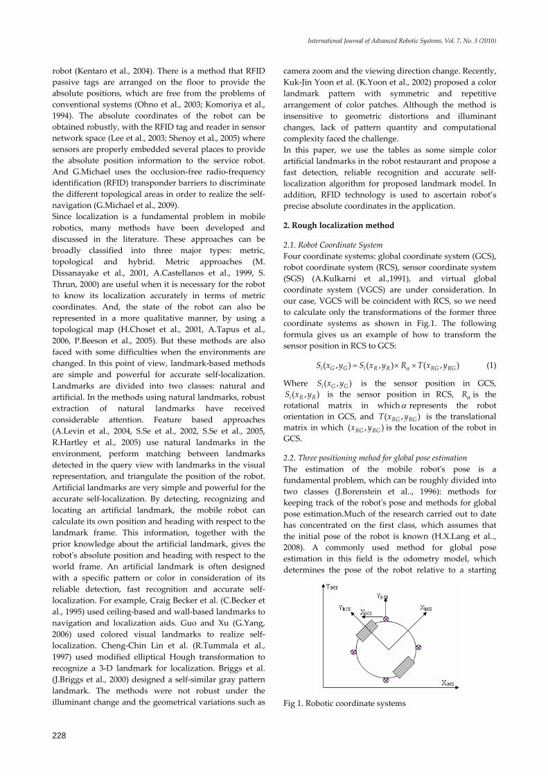
2.1. Robot Coordinate System Four coordinate systems: global coordinate system (GCS), robot coordinate system (RCS), sensor coordinate system (SGS) (A.Kulkarni et al.,1991), and virtual global coordinate system (VGCS) are under consideration. In our case, VGCS will be coincident with RCS, so we need to calculate only the transformations of the former three coordinate systems as shown in Fig.1. The following formula gives us an example of how to transform the sensor position in RCS to GCS:
( , ) ( , ) ( , )i G G i R R RG RGS x y S x y R T x yα= × × (1)
Where ( , )i G GS x y is the sensor position in GCS, ( , )i R RS x y is the sensor position in RCS, Rα is the
rotational matrix in whichα represents the robot orientation in GCS, and ( , )RG RGT x y is the translational matrix in which ( , )RG RGx y is the location of the robot in GCS.
2.2. Three positioning mehod for global pose estimation The estimation of the mobile robot's pose is a fundamental problem, which can be roughly divided into two classes (J.Borenstein et al.., 1996): methods for keeping track of the robot's pose and methods for global pose estimation.Much of the research carried out to date has concentrated on the first class, which assumes that the initial pose of the robot is known (H.X.Lang et al.., 2008). A commonly used method for global pose estimation in this field is the odometry model, which determines the pose of the robot relative to a starting
Fig 1. Robotic coordinate systems
Yu Qing-xiao, Yuan Can, Fu Zhuang and Zhao Yan-zheng: Research of the Localization of Restaurant Service Robot
229
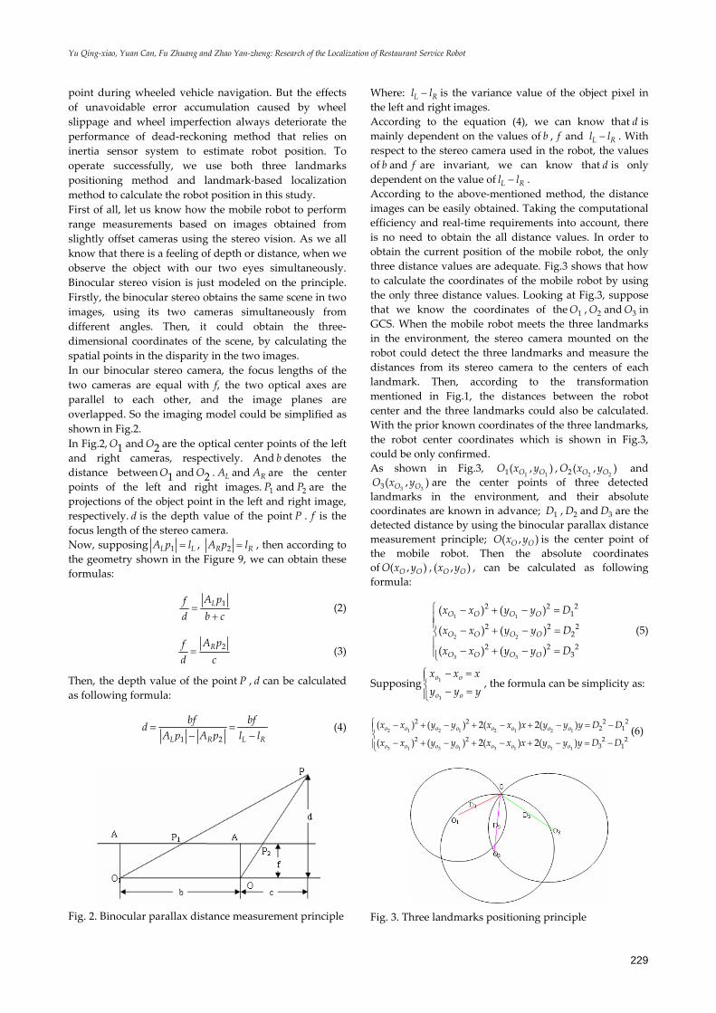
point during wheeled vehicle navigation. But the effects of unavoidable error accumulation caused by wheel slippage and wheel imperfection always deteriorate the performance of dead-reckoning method that relies on inertia sensor system to estimate robot position. To operate successfully, we use both three landmarks positioning method and landmark-based localization method to calculate the robot position in this study. First of all, let us know how the mobile robot to perform range measurements based on images obtained from slightly offset cameras using the stereo vision. As we all know that there is a feeling of depth or distance, when we observe the object with our two eyes simultaneously. Binocular stereo vision is just modeled on the principle. Firstly, the binocular stereo obtains the same scene in two images, using its two cameras simultaneously from different angles. Then, it could obtain the three-dimensional coordinates of the scene, by calculating the spatial points in the disparity in the two images. In our binocular stereo camera, the focus lengths of the two cameras are equal with f, the two optical axes are parallel to each other, and the image planes are overlapped. So the imaging model could be simplified as shown in Fig.2. In Fig.2, 1O and 2O are the optical center points of the left and right cameras, respectively. And b denotes the distance between 1O and 2O . LA and RA are the center points of the left and right images. 1P and 2P are the projections of the object point in the left and right image, respectively. d is the depth value of the point P . f is the focus length of the stereo camera. Now, supposing 1L LA p l= , 2R RA p l= , then according to the geometry shown in the Figure 9, we can obtain these formulas:
1LA pfd b c=
+ (2)
2RA pfd c= (3)
Then, the depth value of the point P , d can be calculated as following formula:
1 2L R L R
bf bfdA p A p l l
= =− −
(4)
Fig. 2. Binocular parallax distance measurement principle
Where: L Rl l− is the variance value of the object pixel in the left and right images. According to the equation (4), we can know that d is mainly dependent on the values of b , f and L Rl l− . With respect to the stereo camera used in the robot, the values of b and f are invariant, we can know that d is only dependent on the value of L Rl l− . According to the above-mentioned method, the distance images can be easily obtained. Taking the computational efficiency and real-time requirements into account, there is no need to obtain the all distance values. In order to obtain the current position of the mobile robot, the only three distance values are adequate. Fig.3 shows that how to calculate the coordinates of the mobile robot by using the only three distance values. Looking at Fig.3, suppose that we know the coordinates of the 1O , 2O and 3O in GCS. When the mobile robot meets the three landmarks in the environment, the stereo camera mounted on the robot could detect the three landmarks and measure the distances from its stereo camera to the centers of each landmark. Then, according to the transformation mentioned in Fig.1, the distances between the robot center and the three landmarks could also be calculated. With the prior known coordinates of the three landmarks, the robot center coordinates which is shown in Fig.3, could be only confirmed. As shown in Fig.3,
1 11( , )O OO x y ,2 22( , )O OO x y and
3 33( , )O OO x y are the center points of three detected landmarks in the environment, and their absolute coordinates are known in advance; 1D , 2D and 3D are the detected distance by using the binocular parallax distance measurement principle; ( , )O OO x y is the center point of the mobile robot. Then the absolute coordinates of ( , )O OO x y , ( , )O Ox y , can be calculated as following formula:
1 1
2 2
3 3
2 2 21
2 2 22
2 2 23
( ) ( )
( ) ( )
( ) ( )
O O O O
O O O O
O O O O
x x y y D
x x y y D
x x y y D
⎧ − + − =⎪⎪ − + − =⎨⎪
− + − =⎪⎩
(5)
Supposing 1
1
o o
o o
x x xy y y
− =⎧⎪⎨ − =⎪⎩
, the formula can be simplicity as:
2 1 2 1 2 1 2 1
3 1 3 1 3 1 3 1
2 2 2 22 1
2 2 2 23 1
( ) ( ) 2( ) 2( )
( ) ( ) 2( ) 2( )o o o o o o o o
o o o o o o o o
x x y y x x x y y y D D
x x y y x x x y y y D D
⎧ − + − + − + − = −⎪⎨
− + − + − + − = −⎪⎩
(6)
Fig. 3. Three landmarks positioning principle

International Journal of Advanced Robotic Systems, Vol. 7, No. 3 (2010)
230
Then, we could calculate the result as follows:
3 1 2 1 2 1 2 1 3 1 3 1
3 1 2 1 2 1 3 1
3 1 2 1 2 1 2 1 3 1 3
2 2 2 2 2 2 2 22 1 3 1
2 2 2 2 2 2 22 1 3 1
( )( ( ) ( ) ) ( )( ( ) ( ) )
2 ( )( ) ( )( )
( )( ( ) ( ) ) ( )( ( ) (
o o o o o o o o o o o o
o o o o o o o o
o o o o o o o o o o o
y y D D x x y y y y D D x x y y
y y x x y y x x
x x D D x x y y x x D D x x yy
− − − − − − − − − − − − −
⎡ ⎤− − − − −⎣ ⎦− − − − − − − − − − − − −
= 1
3 1 2 1 2 1 3 1
2) )
2 ( )( ) ( )( )o
o o o o o o o o
y
x x y y x x y y⎡ ⎤− − − − −⎣ ⎦
(7)
Finally, ( , )O Ox y can be calculated as:
3 1 2 1 2 1 2 1 3 1 3 11
3 1 2 1 2 1 3 1
3 1 2 1 2 1 2 1 31
2 2 2 2 2 2 2 22 1 3 1
2 2 2 2 2 22 1 3 1
( )( ( ) ( ) ) ( )( ( ) ( ) )
2 ( )( ) ( )( )
( )( ( ) ( ) ) ( )( (
o o o o o o o o o o o oo o
o o o o o o o o
o o o o o o o o oo o
y y D D x x y y y y D D x x y yx x
y y x x y y x x
x x D D x x y y x x D D xy y
− − − − − − − − − − − − −= −
⎡ ⎤− − − − −⎣ ⎦− − − − − − − − − −
= − 1 3 1
3 1 2 1 2 1 3 1
2 2) ( ) )
2 ( )( ) ( )( )o o o
o o o o o o o o
x y y
x x y y x x y y
⎧⎪⎪⎪⎨
− − −⎪⎪ ⎡ ⎤− − − − −⎪ ⎣ ⎦⎩
(8)
Once the initial position of the mobile robot has been calculated with above-mentioned approach, considering the continuity of the robot’s coordinates and in order to enhance computing efficiency, we can update the current position of the mobile robot with only two detected landmarks, when the robot is moving around in the environment.
2.3. The landmark-based localization mehod To operate successfully, we also use landmark-based method to detect and calculate the accurate position of the mobile robot in this study. Firstly, to obtain the localization using landmark-based method, we should find the relationship between stereo camera coordinate system and GCS. In this project, there are two freedom degrees in the head of the robot. As shown in Fig.4, α andθ are the rotation degrees; ' ' ' 'OXY Z denotes RCS and '' '' '' ''O X Y Z denotes stereo camera coordinate system; Whenα and θ are equal to zero, '' '' '' ''O X Y Z shifts -6 cm in the X-axis direction relative to ' ' ' 'OXY Z . According to these information, we could obtain the homogeneous transformation matrix T between ' ' ' 'OXY Z and '' '' '' ''O X Y Z .
, , , 6
cos sin 0 0 1 0 0 0 1 0 0 6sin cos 0 0 0 cos sin 0 0 1 0 00 0 1 0 0 sin cos 0 0 0 1 00 0 0 1 0 0 0 1 0 0 0 1
cos sin cos sin sin 6cossin cos cos cos sin 6sin0 sin cos 00
z x xT T T T
T
θ α
θ θθ θ α α
α α
θ θ α θ α θθ θ α θ α θ
α α
−
−⎡ ⎤ ⎡ ⎤ ⎡ ⎤⎢ ⎥ ⎢ ⎥ ⎢ ⎥−⎢ ⎥ ⎢ ⎥ ⎢ ⎥= =⎢ ⎥ ⎢ ⎥ ⎢ ⎥−⎢ ⎥ ⎢ ⎥ ⎢ ⎥⎢ ⎥ ⎢ ⎥ ⎢ ⎥⎣ ⎦ ⎣ ⎦ ⎣ ⎦
−−
⇒ =−0 0 1
⎡ ⎤⎢ ⎥⎢ ⎥⎢ ⎥⎢ ⎥⎢ ⎥⎣ ⎦
(9)
According to the matrix T , the localization of the landmark with respect to RCS could be determined by:
Fig 4. The diagram of stereo camera coordinate system and RCS.
' '' '' '' ''
' '' '' '' ''
' '' '' ''
cos sin cos sin sin 6cos
sin cos cos cos sin 6sin
sin cos1 1 1
x x x y z
y y x y zTz z y z
θ θ α θ α θ
θ θ α θ α θ
α α
⎡ ⎤ ⎡ ⎤ ⎡ ⎤+ + −⎢ ⎥ ⎢ ⎥ ⎢ ⎥⎢ ⎥ ⎢ ⎥ ⎢− + + + ⎥
= =⎢ ⎥ ⎢ ⎥ ⎢ ⎥− +⎢ ⎥ ⎢ ⎥ ⎢ ⎥
⎢ ⎥ ⎢ ⎥ ⎢ ⎥⎣ ⎦ ⎣ ⎦ ⎣ ⎦
(10)
Where: ' ' ' Tx y z⎡ ⎤⎣ ⎦ is the localization of the landmark in
RCS. '' '' '' Tx y z⎡ ⎤
⎣ ⎦ is the localization of the landmark in stereo
coordinate system. According to the geometry shown in Fig.1, we could obtain the homogeneous transformation matrix 'T between GCS and RCS.
0 0
0
0', , ; ,
0
0'
1 0 0 cos sin 0 00 1 0 sin cos 0 00 0 1 0 0 0 1 00 0 0 1 0 0 0 1
cos sin 0sin cos 00 0 1 00 0 0 1
z x x y y
xy
T T T
xy
T
β
β ββ β
β ββ β
⎡ ⎤ ⎡ ⎤⎢ ⎥ ⎢ ⎥−⎢ ⎥ ⎢ ⎥= =⎢ ⎥ ⎢ ⎥⎢ ⎥ ⎢ ⎥⎢ ⎥ ⎢ ⎥⎣ ⎦ ⎣ ⎦
⎡ ⎤⎢ ⎥−⎢ ⎥⇒ =⎢ ⎥⎢ ⎥⎢ ⎥⎣ ⎦
(11)
In this study, we do not care about the coordinate value in the Z-axis direction, so the matrix 'T could be simplified by:
0
''0
cos sinsin cos0 0 1
xT y
β ββ β
⎡ ⎤⎢ ⎥= −⎢ ⎥⎢ ⎥⎣ ⎦
(12)
According to the matrix ''T , the localization of the landmark with respect to GCS could be determined by:
0
0
'' '' ''
'' '' ''
cos sinsin cos
1 0 0 1
cos sin cos sin sin 6cos
sin cos cos cos sin 6sin1
x xy y
x y z
x y z
β ββ β
θ θ α θ α θ
θ θ α θ α θ
⎡ ⎤ ⎡ ⎤⎢ ⎥ ⎢ ⎥= −⎢ ⎥ ⎢ ⎥⎢ ⎥ ⎢ ⎥⎣ ⎦ ⎣ ⎦⎡ ⎤+ + −⎢ ⎥⎢− + + + ⎥⎢ ⎥⎢ ⎥⎣ ⎦
(13)
Where: Tx y⎡ ⎤⎣ ⎦ is the localization of the landmark in
GCS.
0 0Tx y⎡ ⎤⎣ ⎦ is the localization of the robot in GCS.
β represents the robot orientation in GCS. Finally, the localization of the landmark in GCS could be calculated as the equation (13). In the equation (13),
Tx y⎡ ⎤⎣ ⎦ is known in advance; β could be obtained using
the gesture gyroscope; '' '' '' Tx y z⎡ ⎤⎣ ⎦ could be calculated
by binocular parallax distance measurement principle and combination of the camera internal and external parameters; α andθ could be also obtained by the potentiometers or the encoders. So we could calculate the
Yu Qing-xiao, Yuan Can, Fu Zhuang and Zhao Yan-zheng: Research of the Localization of Restaurant Service Robot
231
absolute localization of the robot, 0 0Tx y⎡ ⎤⎣ ⎦ in GCS,
using the mentioned landmark-based method.
2.4. The determination of each landmark method In this study, we use OCR technology to distinguish each landmark which owns its unique table number to localize the mobile robot. Optical Character Recognition (OCR) is the technical term for reading and identifying symbols. In the study, we use template model matching to recognize each table number in the process of the reading characters. Template matching is one of the effective ways of achieving discrete input pattern classification. The essence is to measure the similarity between input model and the template and take the greatest similarity as the respective category of the input pattern. The method is to extract the characteristics from the visual image of the characters and judge by way of the matching function determined with the relevant matching principle. That is, to match by putting the input characters and the standard temple characters into the same classifier. Now, take one-dimensional image processing as an example and the correlation matching algorithm is described as follows: Supposing that the input character is denoted as the input function ( , )f x y , Standard template denotes as the function ( , )F x y , the output of the comparing in the correlator is denoted as ( , )T x y . Random variable is denoted as 1x and 2x . Then the output of the correlator could be denoted as:
1 2 1 2 1 2 1 2( , ) ( , ) ( ( ), ( )) x yT x x y y f x y F x x x y y y d d− − = + − + −∫∫ (14)
When 1 2x x= , 1 2y y= ,and ( , ) ( , )f x y F x y= ,2(0,0) ( , ) x yT f x y d d= ∫∫ which is the autocorrelation
function of input characters. And (0,0) ( , )T T x y≥ , ( , )T x y reaches the peak at (0,0)T , the sub-peaks appear at other standard characters, as long as the peak and sub-peaks are not equal, we can determine and identify the character to be recognized by selecting the appropriate threshold. During the modeling and matching, shape matching methods are all to match the character based-character block. Then, according to their similarity, the recognition results are obtained. During the characters recognition using graph matching principle, generally, binary characters are adopted. Its basic philosophy is establishes standard template iT for each character, the image to be recognized is denoted as Y . Their sizes are all M N× . Matching the unknown model with the template one by one, the similarity iS could be derived from the following formula:
11
11
( )
NM
imn
i NM
imn
Y T
S
T
==
==
×
=
∑
∑
(15)
Where: iY T× denotes as multiplied by the corresponding pixel in the matrixes
Fig. 5. Motion of a differential-drive robot
If max iiS λ> , determine iY T⊂ else refused to identify.
Here λ denotes as the rejection threshold which is generally derived from the experimental analysis.
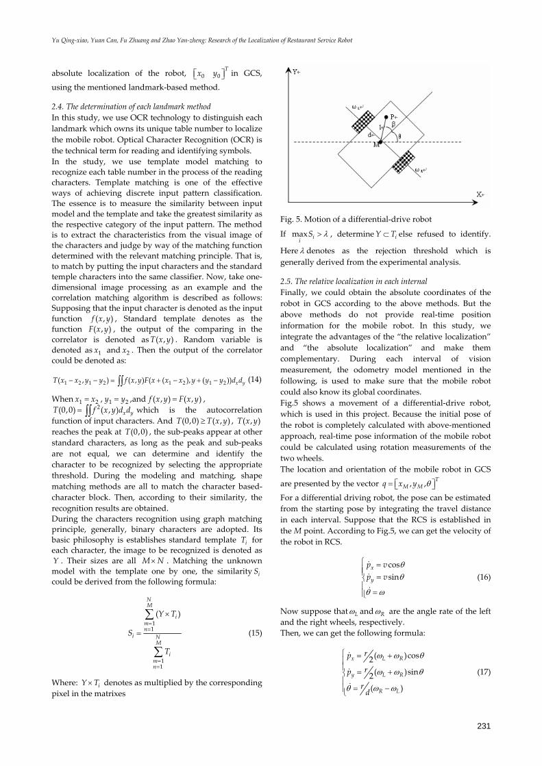
2.5. The relative localization in each internal Finally, we could obtain the absolute coordinates of the robot in GCS according to the above methods. But the above methods do not provide real-time position information for the mobile robot. In this study, we integrate the advantages of the “the relative localization” and “the absolute localization” and make them complementary. During each interval of vision measurement, the odometry model mentioned in the following, is used to make sure that the mobile robot could also know its global coordinates. Fig.5 shows a movement of a differential-drive robot, which is used in this project. Because the initial pose of the robot is completely calculated with above-mentioned approach, real-time pose information of the mobile robot could be calculated using rotation measurements of the two wheels. The location and orientation of the mobile robot in GCS
are presented by the vector , , TM Mq x y θ= ⎡ ⎤⎣ ⎦
For a differential driving robot, the pose can be estimated from the starting pose by integrating the travel distance in each interval. Suppose that the RCS is established in the M point. According to Fig.5, we can get the velocity of the robot in RCS.
cossin
x
y
p vp v
θθ
θ ω
⎧ =⎪⎪ =⎨⎪
=⎪⎩
(16)
Now suppose that Lω and Rω are the angle rate of the left and the right wheels, respectively. Then, we can get the following formula:
( )cos2( )sin2( )
x L R
y L R
R L
rp
rp
rd
ω ω θ
ω ω θ
θ ω ω
⎧ = +⎪⎪ = +⎨⎪
= −⎪⎩
(17)

International Journal of Advanced Robotic Systems, Vol. 7, No. 3 (2010)
232
Therefore, the updated position P for each interval can be calculated as follows:
1
1
1
1
11
( )cos2
( )sin2
( )
i
i i i
i
i i i
i
i
tx x L Rt
ty y L Rt
ti i R Lt
rp p dt
rp p dt
r dtd
ω ω θ
ω ω θ
θ θ ω ω
+
+
+
+
+
+
⎧ = + +⎪⎪⎪ = + +⎨⎪⎪ = + −⎪⎩
∫
∫
∫
(18)
Where: Lω and Rω are the angle rate of the left and the right
wheels, respectively. d is the distance between the two wheels. r is the radius of the two wheels of the robot. t is the sample time. In order to increase the computational efficiency, we suppose that cosθ is a constant value in each interval. So, P could be also calculated as the following equation:
1
1
1
1
11
cos ( )2
sin ( )2
( )
i
i i i
i
i i i
i
i
tx x i L Rt
ty y i L Rt
ti i R Lt
rp p dt
rp p dt
r dtd
θ ω ω
θ ω ω
θ θ ω ω
+
+
+
+
+
+
⎧ = + +⎪⎪⎪ = + +⎨⎪⎪ = + −⎪⎩
∫
∫
∫
(19)
In this situation, the global pose of the mobile robot can be found by computing equation (19) during each interval of binocular vision measurement.
3. Local accuracy localization method
In recent years, the RFID technology has been widely developed and used in the localization of indoor mobile robot. Many researches have been studied such as: Wilson designed a method that maps the tag count percentage to the database of tag count patterns at various attenuation levels (P.Wilson et al., 2007); SpotON (J. Hightower et al., 2001) is a well-known location sensing system that makes use of received signal strength indication (RSSI) to estimate the distance between the active RFID tags and thereby localizing the user with the help of inter-tag distance; Sugunna P takes into account the tag RSSI as well as tag detection rate in his design (P.Subramanian et al., 2008) and yields accuracy 35 cm in the worst case. In our study, we design a smaller RFID reader to reduce the reading distance to about 2 cm in respect to our passive RFID tags. So considering our precision of ±3 cm, we need not consider the RSSI and tag detection rate. In the following part, we introduce our RFID application with ±2 cm accuracy in details.
3.1. The disposal environment of RFID As shown in Fig.6, RFID tags are only disposed on the floor around the pantry table where the dishes cooked by cooking robot are placed. It is because that the localization should be enough accurate in order to make sure the robot could grasp the plate in the pantry table.
Fig. 6. The layout of the passive RFID tags around the pantry table
The absolute coordinates is stored in each RFID tag, and these values will be used in the following localization algorithm. Three RFID readers mounted under the bottom of the robot are used to detect the RFID tags disposed on the floor and obtain the absolute coordinates. The RFID tag enters into the magnetic field range of the RFID reader, when the robot moves over the floor with RFID tags. The absolute coordinates stored in RFID tag will be transmitted by means of using the energy obtained from the radio-frequency signal emitted by the RFID reader. The RFID readers could obtain the absolute coordinates of the RFID tag, when the robot moves over the RFID tag. Then the values are memorized into the computer, and direct the robot how to move. In the course of movement, the robot continually obtains the values of the RFID tags, until the robot arrives at the destination. In the study, the RFID reader only reads one RFID tag each time.
3.2. The RFID-based localization algorithm In the course of movement, the three RFID readers, shown in Fig.7, mounted on the bottom of the robot can detect automatically the RFID tags on the floor. When one RFID tag is in the range of magnetic field of three RFID readers, the RFID readers will obtain the absolute coordinates stored in the RFID tag. As shown in Fig.8, suppose that one RFID tag with absolute coordinates ( , )x y is detected, then the center coordinates of the robot could be gotten as follows. If it is the middle RFID reader that detects the RFID tag, the center coordinates of the robot, 0 0( , )x y , can be denoted as follows.
1 0
1 0
sincos
x l xy l y
αα
+ =+ =
(20)
Fig. 7. The layout of the three RFID readers

Yu Qing-xiao, Yuan Can, Fu Zhuang and Zhao Yan-zheng: Research of the Localization of Restaurant Service Robot
233
Fig. 8. The solution of the center coordinates of the food delivering robot
In the formula: 1 20.38129.7 30 149.512l = + − =
α is the deflection angle between the robot and normal direction of the object. If it is the left RFID reader that detects the RFID tag, the center coordinates of the robot, 0 0( , )x y , can be denoted as follows.
2 0
2 0
sin coscos sin
x l d xy l d y
α αα α
+ + =+ − =
(21)
In the formula: 2 20.38129.7 119.512l = − = 45d =
α is the deflection angle between the robot and normal direction of the object. If it is the right RFID reader that detects the RFID tag, the center coordinates of the robot, 0 0( , )x y , can be denoted as follows.
2 0
2 0
sin coscos sin
x l d xy l d y
α αα α
+ − =+ + =
(22)
In the formula: 2 20.38129.7 119.512l = − =
45d = α is the deflection angle between the robot and normal direction of the object. As shown in Fig.8, suppose that the coordinates of the object is ( , )m mx y . Combining with the center coordinates computed, the deflection angle between the robot and the object can be reckoned.
00
| |atan | |m
m
x xy yβ −= − (23)
Considering the position and normal direction of the objects are different, the differences arouse the different formula for calculating the center coordinates. A universal formula is shown as follows, in order to calculate the center coordinates in the all situation. If it is the left RFID reader that detects the RFID tag, the center coordinates of the robot, 0 0( , )x y , can be denoted as follows.
2 0
2 0
sin( ) cos( )2 2cos( ) sin( )2 2
x l n d n x
y l n d n y
π πα α
π πα α
+ × + + × + =
+ × + − × + ={0,1,2,3}n = (24)
If it is the middle RFID reader that detects the RFID tag, the center coordinates of the robot, 0 0( , )x y , can be denoted as follows.
1 0
1 0
sin( )2cos( )2
x l n x
y l n y
π α
π α
+ × + =
+ × + = {0,1,2,3}n = (25)
If it is the right RFID reader that detects the RFID tag, the center coordinates of the robot, 0 0( , )x y , can be denoted as follows.
2 0
2 0
sin( ) cos( )2 2cos( ) sin( )2 2
x l n d n x
y l n d n y
π πα α
π πα α
+ × + − × + =
+ × + + × + = {0,1,2,3}n = (26)
The deflection angle between the robot and the object can be reckoned:
00
atan mm
x xk y yβ −= − (27)
In the formula, k is the coefficient of the deflection angle, and it may be 1 or -1.
4. Experiments and result analysis
4.1. Experiment setup In the experiments, we build a robot restaurant and lay some tables and a pantry table. And there are many carpets with two different colors on the floor of the restaurant. Some passive tags and three RFID readers with 13.56 MHz frequency are used in the real experiment. The absolute coordinates of each tag is pre-stored, and the tags are also regularly allocated at the specific locations following a designed pattern around the pantry table. The size of the RFID reader antenna is 2.2 2.2× cm and the size of the tag is 2.8 2.8× cm. There is a stereo camera mounted on the head of the robot which send the stereo images to the robot through 1394 bus, and the size of the stereo image is 512×384. Before the experiment, the location and direction of the pantry table are also known in advance. The restaurant service robot is shown in Fig.9.
Fig. 9. The photo of the restaurant service robot
International Journal of Advanced Robotic Systems, Vol. 7, No. 3 (2010)
234
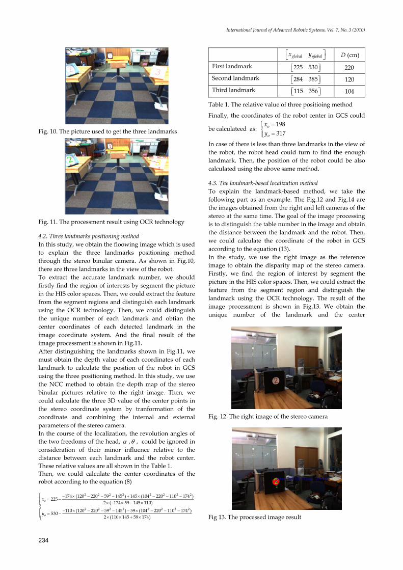
Fig. 10. The picture used to get the three landmarks
Fig. 11. The processment result using OCR technology
4.2. Three landmarks positioning method In this study, we obtain the floowing image which is used to explain the three landmarks positioning method through the stereo binular camera. As shown in Fig.10, there are three landmarks in the view of the robot. To extract the accurate landmark number, we should firstly find the region of interests by segment the picture in the HIS color spaces. Then, we could extract the feature from the segment regions and distinguish each landmark using the OCR technology. Then, we could distinguish the unique number of each landmark and obtian the center coordinates of each detected landmark in the image coordinate system. And the final result of the image processment is shown in Fig.11. After distinguishing the landmarks shown in Fig.11, we must obtain the depth value of each coordinates of each landmark to calculate the position of the robot in GCS using the three positioning method. In this study, we use the NCC method to obtain the depth map of the stereo binular pictures relative to the right image. Then, we could calculate the three 3D value of the center points in the stereo coordinate system by tranformation of the coordinate and combining the internal and external parameters of the stereo camera. In the course of the localization, the revolution angles of the two freedoms of the head, α ,θ , could be ignored in consideration of their minor influence relative to the distance between each landmark and the robot center. These relative values are all shown in the Table 1. Then, we could calculate the center coordinates of the robot according to the equation (8)
2 2 2 2 2 2 2 2
2 2 2 2 2 2 2 2
174 (120 220 59 145 ) 145 (104 220 110 174 )2252 ( 174 59 145 110)
110 (120 220 59 145 ) 59 (104 220 110 174 )5302 (110 145 59 174)
o
o
x
y
⎧ − × − − − + × − − −= −⎪
× − × − ×⎪⎨
− × − − − − × − − −⎪ = −⎪ × × + ×⎩
global globalx y⎡ ⎤
⎣ ⎦ D (cm)
First landmark 225 530⎡ ⎤⎣ ⎦ 220
Second landmark 284 385⎡ ⎤⎣ ⎦ 120
Third landmark 115 356⎡ ⎤⎣ ⎦ 104
Table 1. The relative value of three positioing method
Finally, the coordinates of the robot center in GCS could
be calculateed as: 198317
o
o
xy
=⎧⎪⎨ =⎪⎩
In case of there is less than three landmarks in the view of the robot, the robot head could turn to find the enough landmark. Then, the position of the robot could be also calculated using the above same method.
4.3. The landmark-based localization method To explain the landmark-based method, we take the following part as an example. The Fig.12 and Fig.14 are the images obtained from the right and left cameras of the stereo at the same time. The goal of the image processing is to distinguish the table number in the image and obtain the distance between the landmark and the robot. Then, we could calculate the coordinate of the robot in GCS according to the equation (13). In the study, we use the right image as the reference image to obtain the disparity map of the stereo camera. Firstly, we find the region of interest by segment the picture in the HIS color spaces. Then, we could extract the feature from the segment region and distinguish the landmark using the OCR technology. The result of the image processment is shown in Fig.13. We obtain the unique number of the landmark and the center
Fig. 12. The right image of the stereo camera
Fig 13. The processed image result

Yu Qing-xiao, Yuan Can, Fu Zhuang and Zhao Yan-zheng: Research of the Localization of Restaurant Service Robot
235
Fig. 14. The left image of the stereo camera
Fig. 15. The disparity image of the stereo camera
coordinates of the circle,T
p px y⎡ ⎤⎣ ⎦ , in the image
coordinate system. Once the landmark is distinguished, we could know its global coordinate in the restaurant. Next step, we must obtain the depth value of the the center coordinate of the circle to calculate the position of the robot in the global coordinate system. In this study, we use the NCC method to obtain the depth map of the picture relative to the right image. The Fig.15 shows the depth map of the picture obtained from the stereo camera. After obtaining the depth value of the the center point of the circle, we could calculate the 3D value of the
center point of the circle, '' '' '' Tx y z⎡ ⎤⎣ ⎦ , in the stereo
coordinate system by tranformation of the coordinate and combining the internal and external parameters of the stereo camera. The revolution angles of the two freedoms of the head, α ,θ , and the revolution angle of the robot relative to GCS, β , could be obtained using the potentiometers and the gesture gyroscope. And we have known the location,
Tglobal globalx y⎡ ⎤
⎣ ⎦ , of the landmark in GCS. These relative
values are all shown in the Table 2. The homogeneous translation matrix between the robot coordinate frame and the stereo coordinate frame could be written as:
'' '' '' Tx y z⎡ ⎤⎣ ⎦
Tglobal globalx y⎡ ⎤
⎣ ⎦ β α θ
23.1 175.3 23 T⎡ ⎤⎣ ⎦ 373 430 T
⎡ ⎤⎣ ⎦ 50 15 0
Table 2. The relative value of the landmark-based localization method
1 0 0 60 0.9659 0.2588 00 0.2588 0.9659 00 0 0 1
T
−⎡ ⎤⎢ ⎥⎢ ⎥= ⎢ ⎥−⎢ ⎥⎢ ⎥⎣ ⎦
Then, the location of the landmark relative to RCS could be written as:
'
'
'
1 0 0 6 23.1 17.10 0.9659 0.2588 0 175.3 175.270 0.2588 0.9659 0 23 23.150 0 0 1 1 11
x
y
z
⎡ ⎤ −⎡ ⎤ ⎡ ⎤ ⎡ ⎤⎢ ⎥ ⎢ ⎥ ⎢ ⎥ ⎢ ⎥⎢ ⎥ ⎢ ⎥ ⎢ ⎥ ⎢ ⎥= =⎢ ⎥ ⎢ ⎥ ⎢ ⎥ ⎢ ⎥− −⎢ ⎥ ⎢ ⎥ ⎢ ⎥ ⎢ ⎥⎢ ⎥ ⎢ ⎥ ⎢ ⎥ ⎢ ⎥⎣ ⎦ ⎣ ⎦ ⎣ ⎦⎣ ⎦
The homogeneous translation matrix between the robot coordinate frame and the global coordinate frame could be written as:
0
''0
0.6428 0.76600.7660 0.64280 0 1
xT y
⎡ ⎤⎢ ⎥= −⎢ ⎥⎢ ⎥⎣ ⎦
Therefore, the location of the landmark in GCS can be determined according to the equation (13) as:
0
0
0.6428 0.7660 17.10.7660 0.6428 175.270 0 1 11
global
global
x xy y⎡ ⎤ ⎡ ⎤ ⎡ ⎤⎢ ⎥ ⎢ ⎥ ⎢ ⎥= −⎢ ⎥ ⎢ ⎥ ⎢ ⎥⎢ ⎥ ⎢ ⎥ ⎢ ⎥⎣ ⎦ ⎣ ⎦⎣ ⎦
Because we have known the location T
global globalx y⎡ ⎤⎣ ⎦ ,
the location of the robot origion in GCS could be
calculated as '0 0 221.64 330.44T TO x y= =⎡ ⎤ ⎡ ⎤⎣ ⎦ ⎣ ⎦ . Many
experiment results show that the accuracy of the landmark-based method could be up to ±3 cm, when the distance between the robot and one landmark is less than 2m.
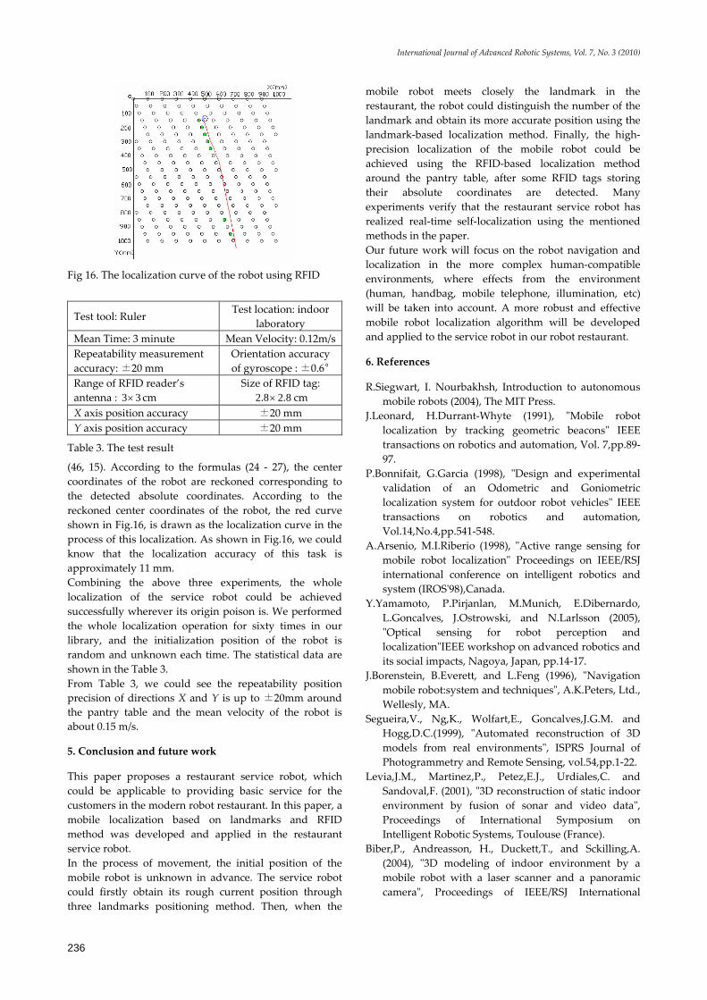
4.4. The local RFID-based localization method In our experiment, we disposal some passive RFID tags on the floor around the pantry table. The mobile robot uses three RFID detectors mounted on the robot to detect the tags and realize the accurate localization. The following example is used to illuminate the process of the localization in details. A suit of data is extracted from experimental data and used to draw the movement routes of the robot. Fig.16 shows the curve of the localization corresponding to these data. In Fig.16, the blue circle indicates the error range of the localization, and the center of the circle is the object point. The RFID tags marked with green show that these RFID tags are detected in the process of this localization. And the red curve shown in Fig.16, is the coordinates curve of the center of the robot in the process of this localization. In Fig.16, there are seven RFID tags detected in the process of this localization, and their coordinates are as flows: (68, 95), (64, 85), (54, 35), (52, 30), (50, 25), (48, 20),
International Journal of Advanced Robotic Systems, Vol. 7, No. 3 (2010)
236
Fig 16. The localization curve of the robot using RFID
Test tool: Ruler Test location: indoor
laboratory Mean Time: 3 minute Mean Velocity: 0.12m/s Repeatability measurement accuracy: ±20 mm
Orientation accuracy of gyroscope : ±0.6º
Range of RFID reader’s antenna : 3 3× cm
Size of RFID tag: 2.8 2.8× cm
X axis position accuracy ±20 mm Y axis position accuracy ±20 mm
Table 3. The test result
(46, 15). According to the formulas (24 - 27), the center coordinates of the robot are reckoned corresponding to the detected absolute coordinates. According to the reckoned center coordinates of the robot, the red curve shown in Fig.16, is drawn as the localization curve in the process of this localization. As shown in Fig.16, we could know that the localization accuracy of this task is approximately 11 mm. Combining the above three experiments, the whole localization of the service robot could be achieved successfully wherever its origin poison is. We performed the whole localization operation for sixty times in our library, and the initialization position of the robot is random and unknown each time. The statistical data are shown in the Table 3. From Table 3, we could see the repeatability position precision of directions X and Y is up to ±20mm around the pantry table and the mean velocity of the robot is about 0.15 m/s.
5. Conclusion and future work
This paper proposes a restaurant service robot, which could be applicable to providing basic service for the customers in the modern robot restaurant. In this paper, a mobile localization based on landmarks and RFID method was developed and applied in the restaurant service robot. In the process of movement, the initial position of the mobile robot is unknown in advance. The service robot could firstly obtain its rough current position through three landmarks positioning method. Then, when the
mobile robot meets closely the landmark in the restaurant, the robot could distinguish the number of the landmark and obtain its more accurate position using the landmark-based localization method. Finally, the high-precision localization of the mobile robot could be achieved using the RFID-based localization method around the pantry table, after some RFID tags storing their absolute coordinates are detected. Many experiments verify that the restaurant service robot has realized real-time self-localization using the mentioned methods in the paper. Our future work will focus on the robot navigation and localization in the more complex human-compatible environments, where effects from the environment (human, handbag, mobile telephone, illumination, etc) will be taken into account. A more robust and effective mobile robot localization algorithm will be developed and applied to the service robot in our robot restaurant.
6. References
R.Siegwart, I. Nourbakhsh, Introduction to autonomous mobile robots (2004), The MIT Press.
J.Leonard, H.Durrant-Whyte (1991), "Mobile robot localization by tracking geometric beacons" IEEE transactions on robotics and automation, Vol. 7,pp.89-97.
P.Bonnifait, G.Garcia (1998), "Design and experimental validation of an Odometric and Goniometric localization system for outdoor robot vehicles" IEEE transactions on robotics and automation, Vol.14,No.4,pp.541-548.
A.Arsenio, M.I.Riberio (1998), "Active range sensing for mobile robot localization" Proceedings on IEEE/RSJ international conference on intelligent robotics and system (IROS'98),Canada.
Y.Yamamoto, P.Pirjanlan, M.Munich, E.Dibernardo, L.Goncalves, J.Ostrowski, and N.Larlsson (2005), "Optical sensing for robot perception and localization"IEEE workshop on advanced robotics and its social impacts, Nagoya, Japan, pp.14-17.
J.Borenstein, B.Everett, and L.Feng (1996), "Navigation mobile robot:system and techniques", A.K.Peters, Ltd., Wellesly, MA.
Segueira,V., Ng,K., Wolfart,E., Goncalves,J.G.M. and Hogg,D.C.(1999), "Automated reconstruction of 3D models from real environments", ISPRS Journal of Photogrammetry and Remote Sensing, vol.54,pp.1-22.
Levia,J.M., Martinez,P., Petez,E.J., Urdiales,C. and Sandoval,F. (2001), "3D reconstruction of static indoor environment by fusion of sonar and video data", Proceedings of International Symposium on Intelligent Robotic Systems, Toulouse (France).
Biber,P., Andreasson, H., Duckett,T., and Sckilling,A. (2004), "3D modeling of indoor environment by a mobile robot with a laser scanner and a panoramic camera", Proceedings of IEEE/RSJ International

Yu Qing-xiao, Yuan Can, Fu Zhuang and Zhao Yan-zheng: Research of the Localization of Restaurant Service Robot
237
Conference on Intelligent Robots and Systems (IROS 2004),Sendai,Japan.
G.Cicirelli, G.Attolico and A.Distante (2006), "Automatic construction of 2D and 3D models during robot inspection", Industrial Robot: An International Journal, vol.33, pp.387-393.
Beata Grzyb, Eris Chinellato, Antonio Morales and Angel P. Del Pobil (2009), "A 3D grasping system based on multimodal visual and tactile processing", Industrial Robot: An International Journal, vol.36, pp.365-369.
D. Hahnel, W. Burgard, D. Fox, K. Fishkin, and M. Philipose (2004), "Mapping and localization with RFID technology," Proc. IEEE Int. Conf on Robotics and Automation, vol. 1, pp. 1015-1020.
A. Cangialosi, J.E. Monaly, and S.C. Yang (2007). Leveraging RFID in hospitals: Patient life cycle and mobility perspectives. IEEE Communications Magazine, 45(9):18–23, Sept.
Kentaro Yamano, Kanji Tanaka, Mitsuru Hirayma, Eiji Kondo, Yoshihiko Kimuro and Michito Matsumoto (2004), "Self-localization of mobile robots with RFID system by using support vector machine," Proc. IEEEIRSJ Int. Conf on Intelligent Robots and Systems, vol. 4, pp. 3756-3761, Sep. 28-Oct. 2.
R.Want (2006). An introduction to RFID technology. IEEE Pervasive Computing, 5(1):25–33, Jan.-March.
Finkenzeller,K.(2003), RFID Handbook: Fundamentals and Applications in Contactless Smart Cards and Identification, 2nd ed., Wiley, New York, NY.
Ohno, K., Tsubouchi, T., Shigematsu, B., Maeyama, S., Yuta, S (2003), "Outdoor navigation of a mobile robot between buildings based on DGPS algorithm, and odometry data fusion," Proc. IEEE Int. Conf on Robotics and Automation, pp. 1978-1984, Sept..
Komoriya, K., Oyama, E (1994), "Position estimation of a mobile robot using optical fiber gyroscope," Proc. IEEEIRSJIGI Int. Conf on Intelligent Robots and Systems, vol. 1, pp. 143-149, Sep. 12-16.
Joo-Ho Lee, Hideki Hashimoto (2003), “Controlling Mobile Robots in Distributed Intelligent Sensor Network,” IEEE Transaction on Industrial Electronics, Vol. 50, No. 5, pp. 890-902, Oct.
Suresh Shenoy and Jindong Tan (2005), "Simultaneous Localization and Mobile Robot Navigation in a Hybrid Sensor Network," Proc. IEEE/RSJ Int. Conf. on Intelligent Robots and Systems, pp. 1636-1641, Aug. 2-6.
G.Michael, S.Florian, K.Thilo (2009), "Robust navigation system based on RFID transponder barriers for the interactive behavior-operated shopping trolley (InBOT)", Industrial Robot:An International Journal, vol.36, pp.377-388.
M.Dissanayake, P.Newman, S.Clark,H.Durrant-Whyte and M.Csorba (2001), "A solution to the simultaneous localization and map building (SLAM) problem", IEEE Transactions on Robotics and Automation, vol.17, no3, pp.229-241.
A.Castellanos, and D.Tardos (1999), Mobile Robot Localization and Map Building: Multisensor Fusion Approach. Kluwer Academic Publisher.
S.Thrun (2000), "Probabilistic algorithms in robotics", Artificial Intelligence Magazine, vol.21,pp.93-109.
H.Choset and K.Nagatani (2001), "Topological simultaneous localization and mapping (SLAM): Toward exact localization without explicit localization", IEEE Transactions On Robotics and Automation, vol.17, no.2, pp.125-137.
A.Tapus and R.Siegwart (2006), "A cognitive modeling of space using fingerprints of places for mobile robot navigation", In Proceedings of the IEEE International Conference on Robotics and Automation (ICRA'06), (Orlando,USA), pp.1188-1193.
P.Beeson, K.Jong, and B.Kuipers (2005), "Toward autonomous topological place detection using the extended voronoi graph", in IEEE International Conference on Robotics and Automaton (ICRA), (Barcelona,Spain), pp.4373-4379.
A.Levin and R.Szeliski (2004), Visual odometry and map correlation. In Proceedings of Computer Vision and Pattern Recognition Conference (CVPR),pages 611-618.
S.Se, D.Lowe and J.Little (2002), Mobile robot localization and mapping with uncertainty using scale-invariant visual landmarks. International Journal of Robotic Research, 8(21):735-760.
S.Se,D.Lowe, and J.Little (2005), Vision-based global localization and mapping for mobile robots. IEEE Transactions on Robotics,21(3):364-375.
C.Anan and R.Hartley (2005), Visual localization and loop-back detection with a high resolution omnidirectional camera. In Proceedings of the Omnivis workshop.
C.Becker,J.Salas,K.Tokusei,J-C.Latorrbe(1995),"Reliable Navigation Using Landmarks",IEEE International Conference on Robotics and Automation,pp.401-406.
G.Yang,X.Xinhe (2006),"Color Landmark Design for Mobile Robot Localization", IMACS Multiconference on "Computational Engineering in Systems Applications" (CESA), October 4-6, Beijing,China.
Cheng-Chih Lin, R.Lal Tummala (1997),"Mobile Robot Navigation Using Artificial Landmarks", Journal of Robotic Systems, vol.14,pp.93-106.
Amy J.Briggs, D.Scharstein, D.Braziunas, C.Dima, P.Wall (2000), "Mobile Robot Navigation Using Self-Similar Landmarks", Processing of the IEEE International Conference on Robotics & Automation, pp.1428-1434.
Kuk-Jin Yoon, In-So Kweon (2002), "Landmark design and real-time landmark tracking for mobile robot localization", Proceedings of SPIE,vol.4573,pp.219-226.
A.Kulkarni, S.Byrd, and O.Pettus (1991), "X-Window Based Graphical of Mobile Robot Simulator for Path Planning and Sensor Fusion Experiments", in the proceeding the 24th Annual of the Simulation Symposium, pp.185-192.

International Journal of Advanced Robotic Systems, Vol. 7, No. 3 (2010)
238
H.X.Lang, Y.Wang and W.Silva (2008), "Mobile Robot Localization and Object Pose Estimation Using Optical Encoder, Vision and Laser Sensors", Proceedings of the IEEE International Conference on Automation and Logistics, Qingdao, China.
P.Wilson, D.Prashanth, H. Aghajan (2007), "Utilizing RFID Signaling Scheme for Localization of Stationary Objects and Speed Estimation of Mobile Objects", IEEE International conference on RFID.
J. Hightower, C. Vakili, G.Borriello and R. Want (2001), "Design and Calibration of the SpotON Ad-Hoc Location Sensing System", Seattle,WA.
P. Subramanian, J. Sommer, S. Schmitt, W. Rosenstiel (2008),"RIL-Reliable RFID based Indoor Localization for Pedestrians ", Telecommunications and Computer Networks,pp. 218-222.