Embed Size (px)
Citation preview
Acta Montanistica Slovaca Ročník 15 (2010), číslo 2, 121-133
121
Research of lignite underground gasification
Karol Kostúr1 and Tibor Sasvári2
Underground Coal Gasification (UCG) is an in situ technique to recover the fuel or feedstock value of coal that is not economically available through conventional recovery technologies. First tentative works directed toward the utilization of the in situ method of gasification under conditions of Northern Bohemian brown-coal basin date back to 1956 in formerly Czechoslovakia. 6 experiments of UCG were realized later. The obtained results did not confirm the technological assumptions of gasification especially regarding the quality of the gas recovered. The average heating capacity reached the value from 1.59 – 3.44 MJ.m-3. Today, similarly all other countries in the world, in Slovakia there is an interest in the revival and perfection of the UCG technology. In this paper it is described a laboratory plant including monitoring and controlling system and some reached results.
During these experiments were find out that the gasification process depends on many factors/parameters. Most the important are topologies/methods, humidity of coal, heat losses, temperatures in relevant zones, composition of oxidation agents and permeability. The calorific value of syngas is 2 - 5 MJ.m-3 if the oxidation agent was used air only. In case of using the air + oxygen mix the calorific value to 10 MJ.m-3 has been obtained.
Keywords: domain history of UCG, experimental objects, monitoring and control system, mathematical modeling, results of a UCG research
Introduction
Coal is our most abundant fossil fuel. While oil and natural gas account for 64 percent of the world’s energy consumption, they total only 31 percent of the world’s known fossil fuel reserves. Today, less than one sixth of the world’s coal is economically accessible. In present time most coal is extracted by classical mining technology. In general, the disadvantages of classical mining (high cost, dangerous work, problems with ecology,…) are well known. Therefore, other technologies are permanently investigated all over the world. They are known as underground technologies. They aim at transforming the coal energy from the solid phase to the liquid or gas phase which makes it possible to extract and transport it to the surface more effectively. Clean coal technologies, among which belongs also underground coal gasification, can be defined as those technologies which improve the environmental acceptability of coal extraction, preparation, and utilization. Underground Coal Gasification (UCG) is an in situ technique to recover the fuel or feedstock value of coal that is not economically available through conventional recovery technologies. Although coal is the most plentiful fossil fuel, only a small fraction of the potential coal reserves can by economically accessed through the shaft or strip mining.
The estimate of coal supplies suitable for UCG and the estimate of potential volume of produced syngas is shown in table 1 [1].
During the last few years UCG technologies attracted a lot of attention in the world. In countries such as for example Australia, Spain, China, Russia and USA a lot has been done to improve these technologies.
First of all they are the methods of geological survey, methods of gasification, control of gasification, drilling technique that must be efficient, energetically efficient and capable to perform directed drill holes (dip and horizontal).
The idea of UCG is not new. As early as 1867 Wilhelm Siemens designed the first underground generator. The well-known chemist Dimitri Mendeleyev came up with the same idea in 1862. The basis of underground gasification is the creation of several drill holes into the coal bed, where, after ignition of the coal, one drill hole serves for feeding the oxidants (air, oxygen, water steam). Gradually, three zones are created (oxidizing, reduction, pyrolysis/drying) and the created gas is conducted through a second, so-called production drill hole to the surface of the bed. The control of the gasification process is the most important step of the entire technology and is developed continually. Our research concentrates upon the control and topology ( methods) of the gasification process with the aim of obtaining gas with a maximum heating capacity.
1 prof. Ing. Karol Kostúr, CSc., Institute of control and informatization of production processes, Faculty of mining, ecology, process
control and geotechnology,Technical University of Košice, Slovak Republic, [email protected] 2 prof. Ing Tibor Sasvari, CSc., Institute of Geo-sciences, Faculty of mining, ecology, process control and geotechnology, Technical
University of Košice, Slovak Republic, [email protected] (Review and revised version 21. 10. 2010)
Karol Kostúr and Tibor Sasvári: Research of underground gasification lignite
122
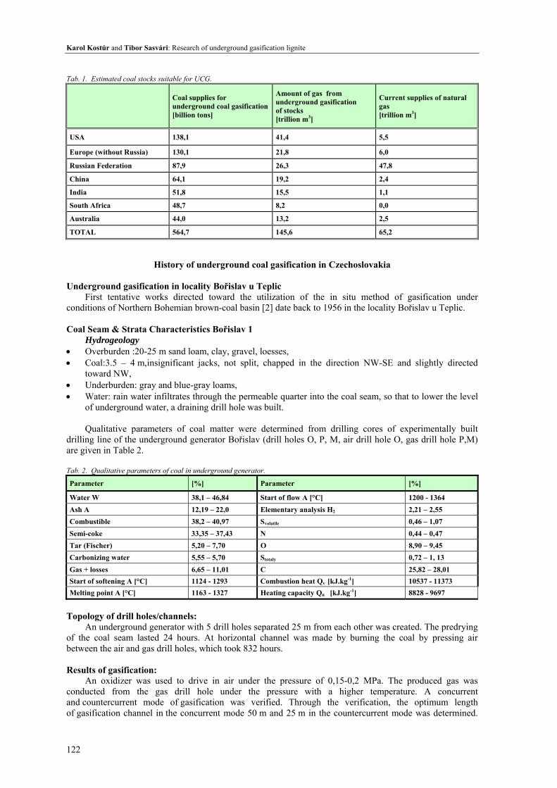
Tab. 1. Estimated coal stocks suitable for UCG.
Coal supplies for underground coal gasification[billion tons]
Amount of gas from underground gasification of stocks [trillion m3]
Current supplies of natural gas [trillion m3]
USA 138,1 41,4 5,5
Europe (without Russia) 130,1 21,8 6,0
Russian Federation 87,9 26,3 47,8
China 64,1 19,2 2,4
India 51,8 15,5 1,1
South Africa 48,7 8,2 0,0
Australia 44,0 13,2 2,5
TOTAL 564,7 145,6 65,2
History of underground coal gasification in Czechoslovakia
Underground gasification in locality Bořislav u Teplic First tentative works directed toward the utilization of the in situ method of gasification under
conditions of Northern Bohemian brown-coal basin [2] date back to 1956 in the locality Bořislav u Teplic. Coal Seam & Strata Characteristics Bořislav 1
Hydrogeology • Overburden :20-25 m sand loam, clay, gravel, loesses, • Coal:3.5 – 4 m,insignificant jacks, not split, chapped in the direction NW-SE and slightly directed
toward NW, • Underburden: gray and blue-gray loams, • Water: rain water infiltrates through the permeable quarter into the coal seam, so that to lower the level
of underground water, a draining drill hole was built. Qualitative parameters of coal matter were determined from drilling cores of experimentally built
drilling line of the underground generator Bořislav (drill holes O, P, M, air drill hole O, gas drill hole P,M) are given in Table 2.
Tab. 2. Qualitative parameters of coal in underground generator.
Parameter [%] Parameter [%]
Water W 38,1 – 46,84 Start of flow A [°C] 1200 - 1364 Ash A 12,19 – 22,0 Elementary analysis H2 2,21 – 2,55 Combustible 38,2 – 40,97 Svolatile 0,46 – 1,07 Semi-coke 33,35 – 37,43 N 0,44 – 0,47 Tar (Fischer) 5,20 – 7,70 O 8,90 – 9,45 Carbonizing water 5,55 – 5,70 Stotaly 0,72 – 1, 13 Gas + losses 6,65 – 11,01 C 25,82 – 28,01 Start of softening A [°C] 1124 - 1293 Combustion heat Qv [kJ.kg-1] 10537 - 11373 Melting point A [°C] 1163 - 1327 Heating capacity Qn [kJ.kg-1] 8828 - 9697
Topology of drill holes/channels:
An underground generator with 5 drill holes separated 25 m from each other was created. The predrying of the coal seam lasted 24 hours. At horizontal channel was made by burning the coal by pressing air between the air and gas drill holes, which took 832 hours. Results of gasification:
An oxidizer was used to drive in air under the pressure of 0,15-0,2 MPa. The produced gas was conducted from the gas drill hole under the pressure with a higher temperature. A concurrent and countercurrent mode of gasification was verified. Through the verification, the optimum length of gasification channel in the concurrent mode 50 m and 25 m in the countercurrent mode was determined.
Acta Montanistica Slovaca Ročník 15 (2010), číslo 2, 121-133
123
The possibilities have been verified to control gasification by the amount and pressure of the air blown in. In Table 3 are shown the results of experimental gasification at the underground generator Bořislav 1.
Tab. 3 Qualitative parameters of experimentally produced gas.
Gas content [%] Parameter
CO2 14,2 – 19,5 Temperature of output gas [˚C] 61,9 – 135,2
O2 0,2 – 1,4 Gas humidity [g.N-1m-3] 184,2 – 781,2
CO 3,8 – 7,6 Amount of produced gas [Nm3] 11,97.103 – 359,947.103
CH4 0,6 – 2,3 Amount of air driven in [Nm3] 23,8.103 – 649,5.103
N2 54,4 – 67,0 Heating capacity of the gas [kJ.Nm-3 ] 1590,0 – 3444,8
Underground gasification at Droužkovice – Březno u Chomutova locality
After evaluating the information and knowledge with the operation of the experimental generator
at Bořislav u Teplic locality it was decided about the continuation and verification of the technology of underground gasification at Droužkovice – Březno u Chomutova locality.
To increase the cost-efficiency of the operation of UCG a generator was designed for a lateral suction of the gas (not tried out anywhere in the world). This solution was to promote a more rational use of materials needed for the operation of UCG – smaller consumption of pipes, fixtures and dilation members of pipings – and had a simpler arrangement of drill holes of the generator. From the technological point of view, an increase in the heating capacity of the produced gas, a higher efficiency of coal seam gasification and a simpler method of control of the power output of the generator was predicted.
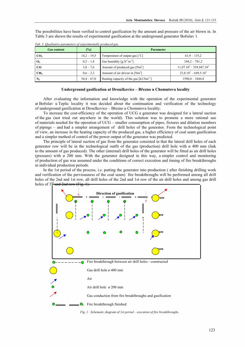
The principle of lateral suction of gas from the generator consisted in that the lateral drill holes of each generator row will be in the technological outfit of the gas (production) drill hole with ø 400 mm (link to the amount of gas produced). The other (internal) drill holes of the generator will be fitted as air drill holes (pressure) with ø 200 mm. With the generator designed in this way, a simpler control and monitoring of production of gas was assumed under the conditions of correct execution and timing of fire breakthroughs in individual production periods.
In the 1st period of the process, i.e. putting the generator into production ( after finishing drilling work and verification of the perviousness of the coal seam) fire breakthroughs will be performed among all drill holes of the 2nd and 1st row, all drill holes of the 2nd and 1st row of the air drill holes and among gas drill holes of 3rd and 2nd row (Fig. 1).
Direction of gasification
1. row 2. row 3. row 4. row
Fire breakthrough between air drill holes - constructed Gas drill hole ø 400 mm Air Air drill hole ø 200 mm
Gas conduction from fire breakthroughs and gasification Fire breakthrough finished
Fig. 1. Schematic diagram of 1st period – execution of fire breakthroughs.
Karol Kostúr and Tibor Sasvári: Research of underground gasification lignite
124
In the gasification period, gasification of coal seam occurs among all air drill holes and gas drill holes
of the 1st and 2nd row. Low-pressure air is blown into the drill holes of 2nd row. The suction of the gas that is generated is performed by the gas drill holes of 2nd and 3rd row. At the same time, breakthroughs between the air drill holes of 3rd and 2nd row and the gas drill holes of 4th and 3rd row is performed. After gasification of the coal seam between the 1st and 2nd row the entire scheme working in the gasification period is shifted by one row of drill holes forward toward the non-gasified seam.
Coal Seam & Strata Characteristics Březno
Based on the geological survey begun as early as 1954 the brown-coal deposit consisted of two
superimposed coal seams. The inter-seam stratum is built with psamito-pelitic sediments that are frequently intermixed with jacks of coal loams. From the viewpoint of the goal of this small experimental generator, lap layers consisting of gray kaolinic- miocenic loams were a suitable material that seals perfectly from both the viewpoint of permeability of rain water infiltrating into the generator and also for the gaseous components created in the generator. Tectonic faults were not discovered.
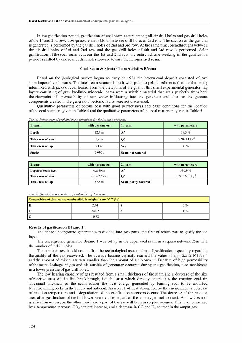
Qualitative parameters of porous coal with good perviousness and basic conditions for the location of the coal seam are given in Table 4 and the qualitative parameters of the coal matter are given in Table 5.
Tab. 4. Parameters of coal and basic conditions for the location of seams.
1. seam with parameters 1. seam with parameters
Depth 22,4 m Ad 19,5 %
Thickness of seam 1,4 m Qid 13 209 kJ.kg-1
Thickness of lap 21 m Wrt 33 %
Stocks 9 930 t Seam not watered
2. seam with parameters 2. seam with parameters
Depth of seam heel cca 40 m Ad 39.29 %
Thickness of seam 2,5 – 2,65 m Qid 13 935.6 kJ.kg-1
Thickness of lap 37,5 m Seam partly watered
Tab. 5. Qualitative parameters of coal matter of 2nd seam. Composition of elementary combustible in original state Vr
daf (%)
H 2,34 S 2,24
C 24,02 N 0,54
O 10,88
Results of gasification Březno 1:
The entire underground generator was divided into two parts, the first of which was to gasify the top layer.
The underground generator Březno 1 was set up in the upper coal seam in a square network 25m with the number of 9 drill holes.
The obtained results did not confirm the technological assumptions of gasification especially regarding the quality of the gas recovered. The average heating capacity reached the value of app. 2,512 MJ.Nm-3 and the amount of mined gas was smaller than the amount of air blown in. Because of high permeability of the seam, leakage of gas and air outside of generator occurred during the gasification, also manifested in a lower pressure of gas drill holes.
The low heating capacity of gas resulted from a small thickness of the seam and a decrease of the size of reactive area of the fire breakthrough, i.e. the area which directly enters into the reaction coal-air. The small thickness of the seam causes the heat energy generated by burning coal to be absorbed by surrounding rocks in the super- and sub-soil. As a result of heat absorption by the environment a decrease of reaction temperature and a degradation of the gasification reactions occurs. The decrease of the reaction area after gasification of the full lower seam causes a part of the air oxygen not to react. A slow-down of gasification occurs, on the other hand, and a part of the gas will burn in surplus oxygen. This is accompanied by a temperature increase, CO2 content increase, and a decrease in CO and H2 content in the output gas.
Acta Montanistica Slovaca Ročník 15 (2010), číslo 2, 121-133
125
The irregular development in the thickness of the 1st coal seam resulted in a full development of fire zone was not achieved, having in turn an adverse effect on the optimum gasification process. The execution of fire breakthroughs in a substantially pervious seam proceeded slowly and the finish of the breakthrough was hard to determine. A fusion of both the technological stages breakthrough-gasification occurred. Results of gasification Březno 2:
The underground generator no. 2 - Březno I was established 40 m deep in the middle group of coal strata (middle seam). The first four rows (out of the total of 8) of working drill holes of the generator PZU (12 drill holes) were finished in upper the footbridge, others in the down footbridge of the 2nd seam. The entire underground generator was divided into two parts, first of which was to gasify only the upper footbridge and the second both footbridge, including the separating the jack. The generator consisted of a total of 25 drill holes. In the first stage (in the first part of the generator) the upper footbridge of the middle seam between the 1st and the 2nd row of the drill holes was gasified. A low-pressure air was blown into air drill holes with the ratio 2:1. The total operation time of the generator was 1,157 hours. 3 060 391 Nm3 of dry gas was produced with the heating capacity of 3,559 MJ.Nm3. The losses of gas were calculated at 37,1 %. The average output per hour of the generator was 2 501 Nm3 of gas. The produced gas was burned in the burner Jerie.
In the second stage the second footbridge of the middle seam was gasified and the possibility of gasification of the top seam in the bottom-top direction was verified. The generator means a group of several drill holes, at least two, on which some of the above-mentioned dependencies or relations of underground gasification was investigated or verified. The knowledge gained from the operation of the generators can be generalized for the given locality of specific geologic-hydro geological conditions of the area and its lithological makup.
Further experiments in the underground gasification at other localities
Two more experiments have been conducted (brown coal + lignite). Due to a limited space
in this contribution, only the experiment at Spořice in SHP will be described. The aim was to find out the conditions of preparation of the generator for gasification (ignition of the seam, creation of the breakthrough and keeping the fire channel in operation) under extreme conditions of thick coal seam layout. In the experimental space, the coal seam reached the thickness of 28 m, is horizontally laid out and has an unified development. .... divide the seam into 3 coal. The quality of coal gives Ad = 30,91 % a Qi
d = 19,974 MJ.kg-1. The depth of the location of the seam is 136 m under the surface level. The coal seam has artesian watering with the free water surface at the depth of 63 m. The tense water surface is created as a result of the location of the seam between two impervious horizons and the difference in altitude of the infiltration region and a specific location in the basin.
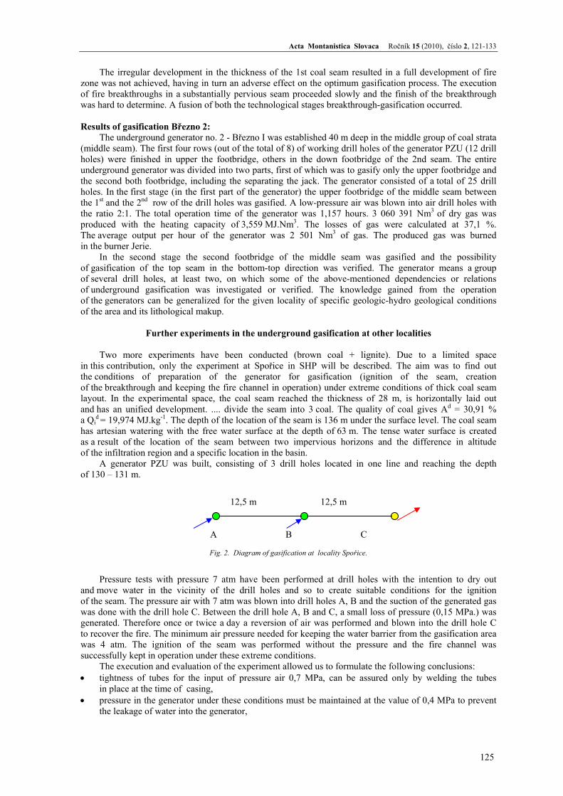
A generator PZU was built, consisting of 3 drill holes located in one line and reaching the depth of 130 – 131 m.
12,5 m 12,5 m
A B C
Fig. 2. Diagram of gasification at locality Spořice.
Pressure tests with pressure 7 atm have been performed at drill holes with the intention to dry out and move water in the vicinity of the drill holes and so to create suitable conditions for the ignition of the seam. The pressure air with 7 atm was blown into drill holes A, B and the suction of the generated gas was done with the drill hole C. Between the drill hole A, B and C, a small loss of pressure (0,15 MPa.) was generated. Therefore once or twice a day a reversion of air was performed and blown into the drill hole C to recover the fire. The minimum air pressure needed for keeping the water barrier from the gasification area was 4 atm. The ignition of the seam was performed without the pressure and the fire channel was successfully kept in operation under these extreme conditions.
The execution and evaluation of the experiment allowed us to formulate the following conclusions: • tightness of tubes for the input of pressure air 0,7 MPa, can be assured only by welding the tubes
in place at the time of casing, • pressure in the generator under these conditions must be maintained at the value of 0,4 MPa to prevent
the leakage of water into the generator,
Karol Kostúr and Tibor Sasvári: Research of underground gasification lignite
126
• flow of air between drill holes at the pressure 0,7 MPa and distance 25 m caused the pressure loss of 0,28 MPa and suppressed the water buoyancy to the value 42 m,
• at the hydrostatic pressure of water 0,63 MPa and air pressure 0,7 MPa, the drill holes and their neighborhood were successfully predried to the extent that it was possible to ignite the seams by the standard method,
• for the industrial use of the PZU technology under similar conditions, the coal seam must be dewatered, • experiments with this generator did not provide enough material for the gasification of thick seams
at greater depths, • gas composition, heating capacity and humidity were identical with the results from the generators
in Březno.
Current research of lignite gasification in Slovakia
Similarly to all other countries in the world (mainly in Europe) in Slovakia there is an interest in the revival and perfection of the technology of underground gasification for pragmatic reasons: • almost exhausted sources of coal from the point of view of cost-efficiency of the classical underground
mining, • recent oil price shock.
The goal is to develop a technology but first of all an efficient control of underground gasification
of lignite under favorable hydro geological conditions (non-watered, with impervious …., in depths app. 200-400 m.
In the first stage, a laboratory research is planned to conduct (3-4 years) and in the second stage the gained knowledge will verified at the chosen deposit of the Upper Nitra lignite basin (3 years). At present an intense laboratory research is conducted whose brief characteristics are the subject.
From the point of its view of content, the research is directed toward the investigation of quasihorizontal gasification: • specification of the essence of the gasification mechanism (the release of gases from …. , oxidation,
reduction, pyrolysis, drying,…), • efficient methods/topologies of gasification (non-channel, single-channel, multi-channel, with long wall
…), • direction of gasification (concurrent, countercurrent), • suitable tools for monitoring the process (temperature sensors, analyzers, pressure meters, humidity
probes,…), • control system (various types of regulators, different types and ratios of oxidizers, optimum control), • possibility of capture of CO2 during the process of gasification.
From the viewpoint of used methods, one can characterize the research by 2 approaches:
• experimental [3, 4], • mathematical modeling, including simulation studies [5, 6, 7].
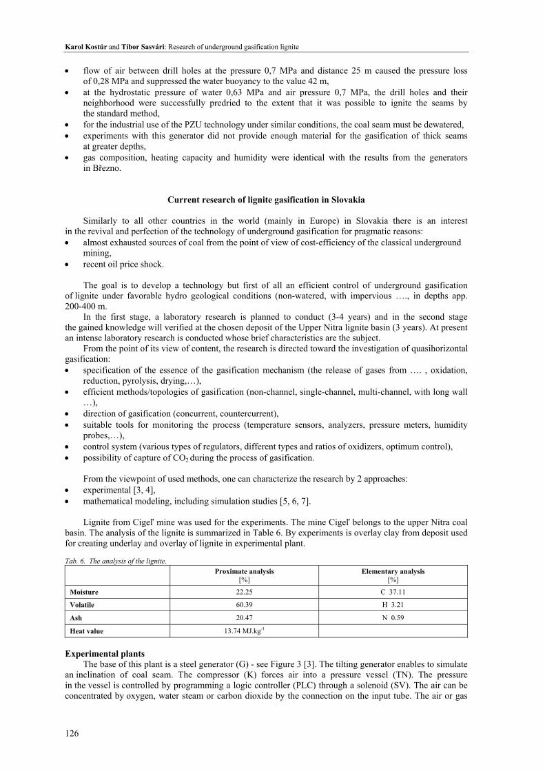
Lignite from Cigeľ mine was used for the experiments. The mine Cigeľ belongs to the upper Nitra coal
basin. The analysis of the lignite is summarized in Table 6. By experiments is overlay clay from deposit used for creating underlay and overlay of lignite in experimental plant. Tab. 6. The analysis of the lignite.
Proximate analysis [%]
Elementary analysis [%]
Moisture 22.25 C 37.11
Volatile 60.39 H 3.21
Ash 20.47 N 0.59
Heat value 13.74 MJ.kg-1
Experimental plants
The base of this plant is a steel generator (G) - see Figure 3 [3]. The tilting generator enables to simulate an inclination of coal seam. The compressor (K) forces air into a pressure vessel (TN). The pressure in the vessel is controlled by programming a logic controller (PLC) through a solenoid (SV). The air can be concentrated by oxygen, water steam or carbon dioxide by the connection on the input tube. The air or gas
Acta Montanistica Slovaca Ročník 15 (2010), číslo 2, 121-133
127
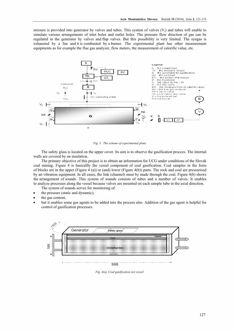
mixture is provided into generator by valves and tubes. This system of valves (Vi) and tubes will enable to simulate various arrangements of inlet holes and outlet holes. The pressure flow direction of gas can be regulated in the generator by valves and flap valves. But this possibility is very limited. The syngas is exhausted by a fan and it is combusted by a burner. The experimental plant has other measurement equipments as for example the flue gas analyzer, flow meters, the measurement of calorific value, etc.
Fig. 3. The scheme of experimental plant.
The safety glass is located on the upper cover. Its aim is to observe the gasification procces. The internal
walls are covered by an insulation. The primary objective of this project is to obtain an information for UCG under conditions of the Slovak
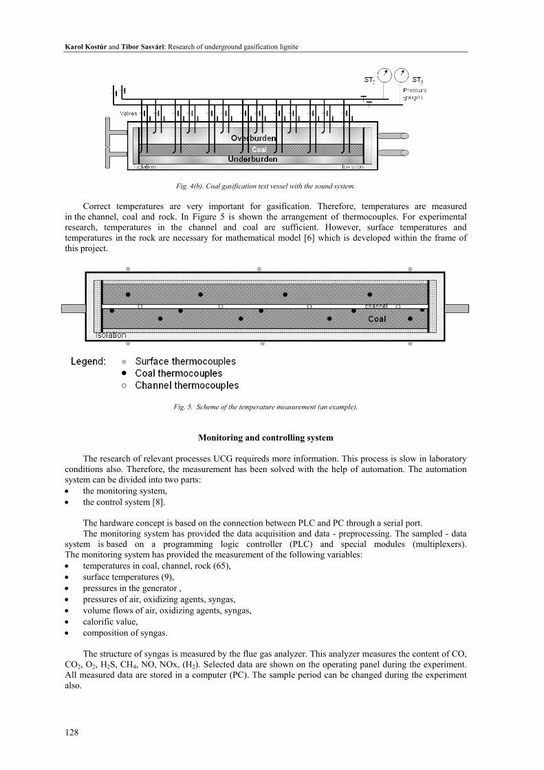
coal mining. Figure 4 is basicallly the vessel component of coal gasification. Coal samples in the form of blocks are in the upper (Figure 4 (a)) or (and) lower (Figure 4(b)) parts. The rock and coal are pressurised by an vibration equipment. In all cases, the link (channel) must by made through the coal. Figure 4(b) shows the arrangement of sounds. This system of sounds consists of tubes and a number of valves. It enables to analyze processes along the vessel because valves are mounted on each sample tube in the axial direction.
The system of sounds serves for monitoring of: • the pressure (static and dynamic), • the gas content, • but it enables some gas agents to be added into the process also. Addition of the gas agent is helpful for
control of gasification processes.
Fig. 4(a). Coal gasification test vessel.
Karol Kostúr and Tibor Sasvári: Research of underground gasification lignite
128
Fig. 4(b). Coal gasification test vessel with the sound system.
Correct temperatures are very important for gasification. Therefore, temperatures are measured
in the channel, coal and rock. In Figure 5 is shown the arrangement of thermocouples. For experimental research, temperatures in the channel and coal are sufficient. However, surface temperatures and temperatures in the rock are necessary for mathematical model [6] which is developed within the frame of this project.
Fig. 5. Scheme of the temperature measurement (an example).
Monitoring and controlling system
The research of relevant processes UCG requireds more information. This process is slow in laboratory conditions also. Therefore, the measurement has been solved with the help of automation. The automation system can be divided into two parts: • the monitoring system, • the control system [8].
The hardware concept is based on the connection between PLC and PC through a serial port. The monitoring system has provided the data acquisition and data - preprocessing. The sampled - data
system is based on a programming logic controller (PLC) and special modules (multiplexers). The monitoring system has provided the measurement of the following variables: • temperatures in coal, channel, rock (65), • surface temperatures (9), • pressures in the generator , • pressures of air, oxidizing agents, syngas, • volume flows of air, oxidizing agents, syngas, • calorific value, • composition of syngas.
The structure of syngas is measured by the flue gas analyzer. This analyzer measures the content of CO,
CO2, O2, H2S, CH4, NO, NOx, (H2). Selected data are shown on the operating panel during the experiment. All measured data are stored in a computer (PC). The sample period can be changed during the experiment also.
Acta Montanistica Slovaca Ročník 15 (2010), číslo 2, 121-133
129
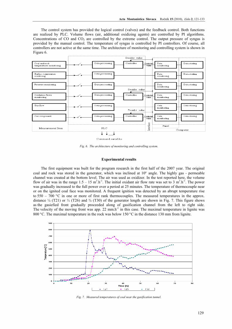
The control system has provided the logical control (valves) and the feedback control. Both functions are realized by PLC. Volume flows (air, additional oxidizing agents) are controlled by PI algorithms. Concentrations of CO and CO2 are controlled by the extreme control. The output pressure of syngas is provided by the manual control. The temperature of syngas is controlled by PI controllers. Of course, all controllers are not active at the same time. The architecture of monitoring and controlling system is shown in Figure 6.
Fig. 6. The architecture of monitoring and controlling system.
Experimental results
The first equipment was built for the program research in the first half of the 2007 year. The original coal and rock was stored in the generator, which was inclined at 10° angle. The highly gas - permeable channel was created at the bottom level. The air was used as oxidizer. In the test reported here, the volume flow of air was in the range 1.5 – 15 m3.h-1. The initial oxidant air flow rate was set to 3 m3.h-1. The power was gradually increased to the full power over a period at 25 minutes. The temperature of thermocouple near or on the ignited coal face was monitored. A frequent ignition was detected by an abrupt temperature rise to 550 – 700 °C in one or more of first rank thermocouples. The measured temperatures in the approx. distance ¼ (T21) or ½ (T26) and ¾ (T30) of the generator length are shown in Fig. 7. This figure shows as the gasiefied front gradually proceeded along of gasification channel from the left to right side. The velocity of the moving front was app. 22 mm.h-1 in this case. The maximal temperature in lignite was 800 °C. The maximal temperature in the rock was below 150 °C in the distance 130 mm from lignite.
Fig. 7. Measured temperatures of coal near the gasification tunnel.
Karol Kostúr and Tibor Sasvári: Research of underground gasification lignite
130
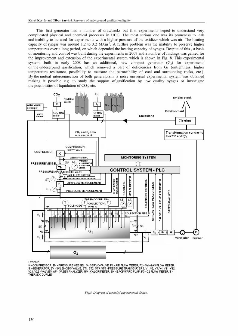
This first generator had a number of drawbacks but first experiments heped to understand very complicated physical and chemical processes in UCG. The most serious one was its proneness to leak and inability to be used for experiments with a higher pressure of the oxidizer which was air. The heating capacity of syngas was around 1.2 to 3.2 MJ.m-3. A further problem was the inability to preserve higher temperatures over a long period, on which depended the heating capacity of syngas. Despite of this , a basis of monitoring and control was built during the experiments in 2007 and a number of findings was gained for the improvement and extension of the experimental system which is shown in Fig. 8. This experimental system, built in early 2008 has an additional, new compact generator (G2) for experiments on the underground gasification, which removed a part of deficiencies from G1 (untightness, higher temperature resistance, possibility to measure the permeability of coal and surrounding rocks, etc.). By the mutual interconnection of both generatorsm, a more universal experimental system was obtained making it possible e.g. to study the support of gasification by low quality syngas or investigate the possibilities of liquidation of CO2, etc.
Fig.8 Diagram of extended experimental device.
Acta Montanistica Slovaca Ročník 15 (2010), číslo 2, 121-133
131
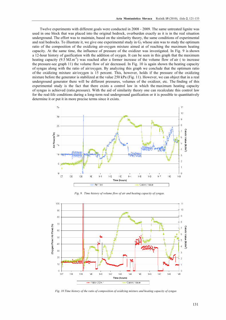
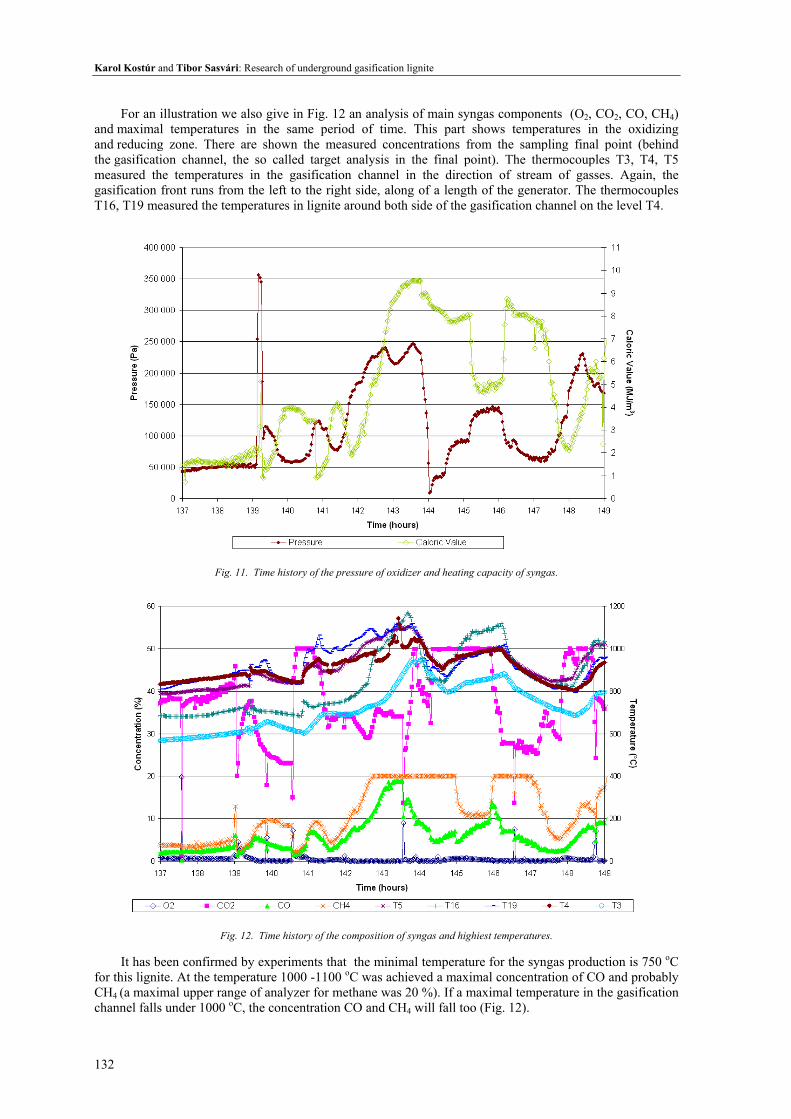
Twelve experiments with different goals were conducted in 2008 - 2009. The same untreated lignite was used in one block that was placed into the original bedrock, overburden exactly as it is in the real situation underground. The effort was to maintain, based on the similarity theory, the same conditions of experimental and real bedrocks. To illustrate it, we give one experimental study in G2 whose aim was to study the optimum ratio of the composition of the oxidizing air-oxygen mixture aimed at of reaching the maximum heating capacity. At the same time, the influence of pressure of the oxidizer was investigated. In Fig. 9 is shown a 12-hour history of gasification with the addition of oxygen. It can be seen in this graph that the maximum heating capacity (9.5 MJ.m-3) was reached after a former increase of the volume flow of air ( to increase the pressure-see graph 11) the volume flow of air decreased. In Fig. 10 is again shown the heating capacity of syngas along with the ratio of air/oxygen. By analyzing this graph we conclude that the optimum ratio of the oxidizing mixture air/oxygen is 15 percent. This, however, holds if the pressure of the oxidizing mixture before the generator is stabilized at the value 250 kPa (Fig. 11). However, we can object that in a real underground generator there will be different pressures, volumes of the oxidizer, etc. The finding of this experimental study is the fact that there exists a control law in which the maximum heating capacity of syngas is achieved (ratio,pressure). With the aid of similarity theory one can recalculate this control law for the real-life conditions during a long-term real underground gasification or it is possible to quantitatively determine it or put it in more precise terms since it exists.
Fig. 9. Time history of volume flow of air and heating capacity of syngas.
Fig. 10 Time history of the ratio of composition of oxidizing mixture and heating capacity of syngas
Karol Kostúr and Tibor Sasvári: Research of underground gasification lignite
132
For an illustration we also give in Fig. 12 an analysis of main syngas components (O2, CO2, CO, CH4)
and maximal temperatures in the same period of time. This part shows temperatures in the oxidizing and reducing zone. There are shown the measured concentrations from the sampling final point (behind the gasification channel, the so called target analysis in the final point). The thermocouples T3, T4, T5 measured the temperatures in the gasification channel in the direction of stream of gasses. Again, the gasification front runs from the left to the right side, along of a length of the generator. The thermocouples T16, T19 measured the temperatures in lignite around both side of the gasification channel on the level T4.
Fig. 11. Time history of the pressure of oxidizer and heating capacity of syngas.
Fig. 12. Time history of the composition of syngas and highiest temperatures.
It has been confirmed by experiments that the minimal temperature for the syngas production is 750 oC
for this lignite. At the temperature 1000 -1100 oC was achieved a maximal concentration of CO and probably CH4 (a maximal upper range of analyzer for methane was 20 %). If a maximal temperature in the gasification channel falls under 1000 oC, the concentration CO and CH4 will fall too (Fig. 12).
Acta Montanistica Slovaca Ročník 15 (2010), číslo 2, 121-133
133
Conclusions
Underground gasification is one of alternatives how to provide energy from coal supplies that are
economically inaccessible with present-time methods of underground mining. Alternatively, this technology can be used to recover energy from spent coal mines because there are still large volumes of coal not mined for technological reasons. During the last 50 years, the technology of underground gasification was able to increase at least threefold the heating capacity of the mined syngas. A necessary condition for its application, however, is the economic efficiency and profitability. The costs for its realization are not small. Therefore the current efforts are directed toward achieving as much knowledge as possible about efficient methods of gasification, optimum control and maximum recovery of energy from coal. Therefore the laboratory research with its unique role should be performed before the testing experiment and after a successful verification of specific technology (depending on the type, structure and hydrogeology of the coal deposit) on a real deposit can a potential industrial realization be carried out.
Acknowledgements: This work was supported by the Slovak Research and Development Agency under the contract No. APVV-0582-06 and mine company HBP a.s. Prievidza.
References
[1] ECOAL, 10/2006, page 4,WCI [2] Valeš, J., Šafářová, M.: Zplynovaní uhlí (Coal Gasification), Report VV-123/06, Most VUHU, pp.77. [3] Kostúr, K., Kačúr J.: Design of experimental equipment for underground coal gasification. Proceedings
of ICCC”07, TU BERG Košice, ISBN 978-80-8073-1, pp.334-338 (2007) [4] Kostur, K., Blistanova, M.:Research of UCG in laboratory, Workshop „Effective Utilization of Coal
Resources and Advanced Technologies“,TCE Ankara, March, 2008. [5] Kostúr K.: Structur of mathematical modeling for UCG based on thermodynamics. Proceedings
of ICCC”07,TU BERG Košice,ISBN 978-80-8073-1,pp.-323-327 (2007). [6] Kostúr K.: The mathematical modeling of relevant processes for underground coal gasification,
Proceedings of 5th International symposium on Earth Science and Technology, Kyushu University Fukuoka,ISBN 978-4-9902356-8-1,pp.475-480 (2007).
[7] Kostúr K.: The Experimental Equipment and its Automation for Underground Coal Gasification,Proceedings of the Sixteenth International Symposium on Mine Planning and Equipment Selection (MPES 2007) and the Tenth International Symposium on Environmental Issues and Waste Management in Energy and Mineral Production (SWEMP 2007), CD ROM published by The Reading Matrix Inc., Irvine, CA, USA, ISSN 1913-6528, ISBN 978-0-9784416-0-9, pp. 506-511.
[8] Kostúr, K., Kačúr, J.: The monitoring and control of underground coal gasification in laboratory conditions, Acta Montanistica Slovaca ,Vol. 13 (2008), No. 1, 111-117, actamont.tuke.sk, ISSN 1335-1788.