Embed Size (px)
Citation preview
Research of Influence of the Inlet Elements Design on a Hydraulic Efficiency of an Intermediate Stage in the BB3-Type Multi-Stage Centrifugal Pumps
A. S. Nadtochiy1* and I. B. Tverdohleb2
1JSC "HMS Livhydromash", Moscow branch, Russia 2LLC "Management Company"HMS Group", Moscow, Russia
Abstract. This article presents the results of computational studies for
different options of inlet design in an intermediate stage of a BB3 type multi-
stage pump intended for transportation of crude oil and other similar liquids.
Hydraulic losses in the flow part elements are compared for three different
options of the inlet blades in the return channels of an intermediate stage.
1 Introduction
This work was carried out as part of a program on production of the BB3 type pumps. This
refers to the volute centrifugal pumps with transfer channels that meet the requirements of
GOST 32601-2013 [1].
These pumps are widely used as feed group pumps in the oil and gas refining,
petrochemical and chemical industry, petroleum production, oil and oil products trunk
transportation.
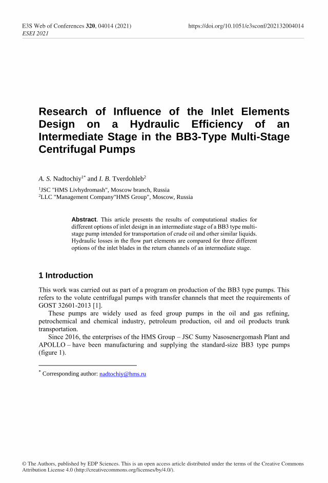
Since 2016, the enterprises of the HMS Group – JSC Sumy Nasosenergomash Plant and
APOLLO – have been manufacturing and supplying the standard-size BB3 type pumps
(figure 1).
* Corresponding author: [email protected]
© The Authors, published by EDP Sciences. This is an open access article distributed under the terms of the Creative Commons Attribution License 4.0 (http://creativecommons.org/licenses/by/4.0/).
E3S Web of Conferences 320, 04014 (2021)ESEI 2021
https://doi.org/10.1051/e3sconf/202132004014
(a) (b)
Fig. 1. AMG 150L.5x350 (a) and AMG 100L.13x290 (b) units.
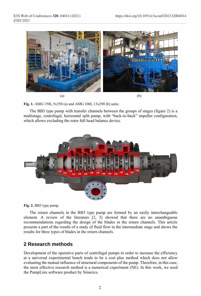
The BB3 type pump with transfer channels between the groups of stages (figure 2) is a
multistage, centrifugal, horizontal split pump, with “back-to-back” impeller configuration,
which allows excluding the rotor full head balance device.
Fig. 2. BB3 type pump.
The return channels in the BB3 type pump are formed by an easily interchangeable
element. A review of the literature [2, 3] showed that there are no unambiguous
recommendations regarding the design of the blades in the return channels. This article
presents a part of the results of a study of fluid flow in the intermediate stage and shows the
results for three types of blades in the return channels.
2 Research methods
Development of the operative parts of centrifugal pumps in order to increase the efficiency
at a universal experimental bench tends to be a cost plus method which does not allow
evaluating the mutual influence of structural components of the pump. Therefore, in this case,
the most effective research method is a numerical experiment (NE). In this work, we used
the PumpLinx software product by Simerics.
2
E3S Web of Conferences 320, 04014 (2021)ESEI 2021
https://doi.org/10.1051/e3sconf/202132004014
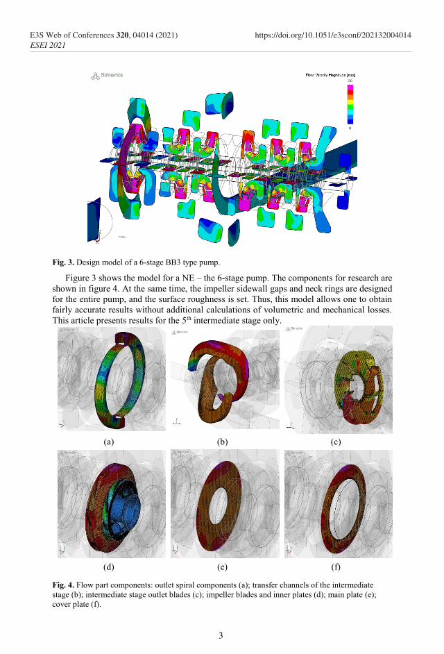
Fig. 3. Design model of a 6-stage BB3 type pump.
Figure 3 shows the model for a NE – the 6-stage pump. The components for research are
shown in figure 4. At the same time, the impeller sidewall gaps and neck rings are designed
for the entire pump, and the surface roughness is set. Thus, this model allows one to obtain
fairly accurate results without additional calculations of volumetric and mechanical losses.
This article presents results for the 5th intermediate stage only.
(a) (b) (c)
(d) (e) (f)
Fig. 4. Flow part components: outlet spiral components (a); transfer channels of the intermediate
stage (b); intermediate stage outlet blades (c); impeller blades and inner plates (d); main plate (e);
cover plate (f).
3
E3S Web of Conferences 320, 04014 (2021)ESEI 2021
https://doi.org/10.1051/e3sconf/202132004014
The inlet pressure of 0 MPA was set. The flow rate was set at the outlet. The calculations
were carried out under the unsteady mode with an angular step of rotation of 5°, because
these results are more accurate, based on the experience of previous works and in comparison
with the results obtained during the bench tests. The following boundary conditions were
specified: n = 2950 rpm, t = 20 °C, ρ = 998 kg/m3. The number of nodes in the grid for the
entire model is 7.8 mln. The NE results are presented for 5 flow levels: 0.75 of the rated flow,
0.88 of the rated flow, rated flow, 1.13 of the rated flow, 1.25 of the rated flow.
3 Research results and discussion
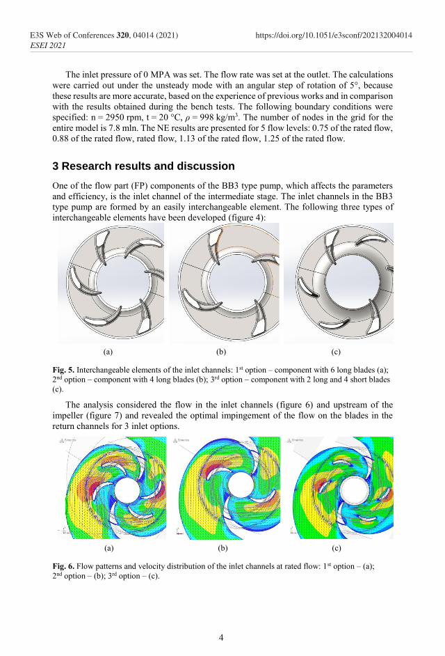
One of the flow part (FP) components of the BB3 type pump, which affects the parameters
and efficiency, is the inlet channel of the intermediate stage. The inlet channels in the BB3
type pump are formed by an easily interchangeable element. The following three types of
interchangeable elements have been developed (figure 4):
(a) (b) (c)
Fig. 5. Interchangeable elements of the inlet channels: 1st option – component with 6 long blades (a);
2nd option – component with 4 long blades (b); 3rd option – component with 2 long and 4 short blades
(c).
The analysis considered the flow in the inlet channels (figure 6) and upstream of the
impeller (figure 7) and revealed the optimal impingement of the flow on the blades in the
return channels for 3 inlet options.
(a) (b) (c)
Fig. 6. Flow patterns and velocity distribution of the inlet channels at rated flow: 1st option – (a);
2nd option – (b); 3rd option – (c).
4
E3S Web of Conferences 320, 04014 (2021)ESEI 2021
https://doi.org/10.1051/e3sconf/202132004014
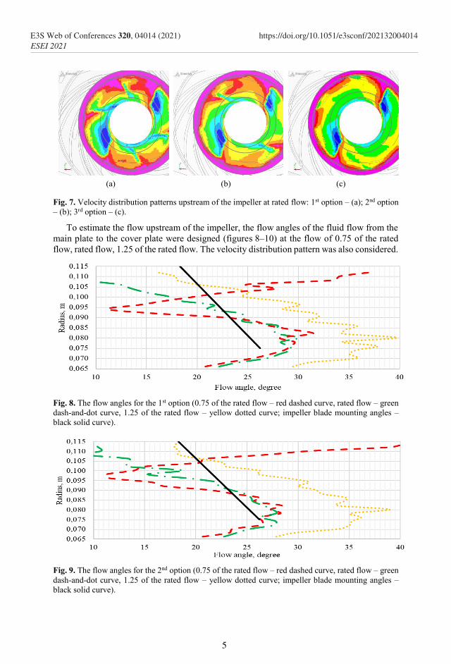
(a) (b) (c)
Fig. 7. Velocity distribution patterns upstream of the impeller at rated flow: 1st option – (a); 2nd option
– (b); 3rd option – (c).
To estimate the flow upstream of the impeller, the flow angles of the fluid flow from the
main plate to the cover plate were designed (figures 8–10) at the flow of 0.75 of the rated
flow, rated flow, 1.25 of the rated flow. The velocity distribution pattern was also considered.
Fig. 8. The flow angles for the 1st option (0.75 of the rated flow – red dashed curve, rated flow – green
dash-and-dot curve, 1.25 of the rated flow – yellow dotted curve; impeller blade mounting angles –
black solid curve).
Fig. 9. The flow angles for the 2nd option (0.75 of the rated flow – red dashed curve, rated flow – green
dash-and-dot curve, 1.25 of the rated flow – yellow dotted curve; impeller blade mounting angles –
black solid curve).
5
E3S Web of Conferences 320, 04014 (2021)ESEI 2021
https://doi.org/10.1051/e3sconf/202132004014
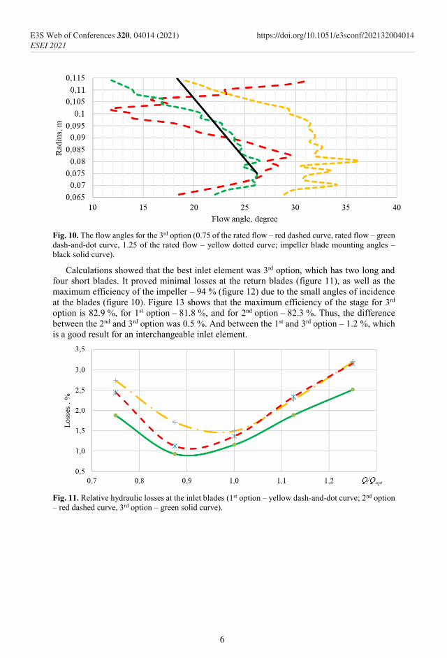
Fig. 10. The flow angles for the 3rd option (0.75 of the rated flow – red dashed curve, rated flow – green
dash-and-dot curve, 1.25 of the rated flow – yellow dotted curve; impeller blade mounting angles –
black solid curve).
Calculations showed that the best inlet element was 3rd option, which has two long and
four short blades. It proved minimal losses at the return blades (figure 11), as well as the
maximum efficiency of the impeller – 94 % (figure 12) due to the small angles of incidence
at the blades (figure 10). Figure 13 shows that the maximum efficiency of the stage for 3rd
option is 82.9 %, for 1st option – 81.8 %, and for 2nd option – 82.3 %. Thus, the difference
between the 2nd and 3rd option was 0.5 %. And between the 1st and 3rd option – 1.2 %, which
is a good result for an interchangeable inlet element.
Fig. 11. Relative hydraulic losses at the inlet blades (1st option – yellow dash-and-dot curve; 2nd option
– red dashed curve, 3rd option – green solid curve).
6
E3S Web of Conferences 320, 04014 (2021)ESEI 2021
https://doi.org/10.1051/e3sconf/202132004014
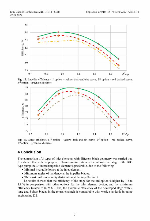
Fig. 12. Impeller efficiency (1st option – yellow dash-and-dot curve; 2nd option – red dashed curve,
3rd option – green solid curve).
Fig. 13. Stage efficiency (1st option – yellow dash-and-dot curve; 2nd option – red dashed curve,
3rd option – green solid curve).
4 Conclusion
The comparison of 3 types of inlet elements with different blade geometry was carried out.
It is shown that with the purpose of losses minimization in the intermediate stage of the BB3
type pump the 3rd interchangeable element is preferable, due to the following:
Minimal hydraulic losses at the inlet element.
Minimum angles of incidence at the impeller blades.
The most uniform velocity distribution at the impeller inlet.
The results showed that the efficiency of the stage for the 3rd option is higher by 1.2 to
1.8 % in comparison with other options for the inlet element design, and the maximum
efficiency totaled to 82.9 %. Thus, the hydraulic efficiency of the developed stage with 2
long and 4 short blades in the return channels is comparable with world standards in pump
engineering [2].
7
E3S Web of Conferences 320, 04014 (2021)ESEI 2021
https://doi.org/10.1051/e3sconf/202132004014

References
1. GOST 32601-2013, Centrifugal pumps for petroleum, petrochemical and natural gas
industries. General technical requirements (mod. ISO13709:2009) (Мoscow:
Standardinform)
2. J. F. Gülich, Centrifugal pumps (Villeneuve, Switzerland: Springer International
Publishing), 2020
3. V. S. Lobanoff and R. R. Ross, Centrifugal Pumps: Design and Application (Elsevier
Inc.), 1992
4. S. S. Rudnev, Fundamentals of the theory of blade grids (Moscow) p 78, 1976
8
E3S Web of Conferences 320, 04014 (2021)ESEI 2021
https://doi.org/10.1051/e3sconf/202132004014