Embed Size (px)
Citation preview
RESEARCH MEMORANDUM EFFECTS O F HIGH-UFT AND STALL-CONTROL DEVICES, FUSELAGE,
AND BOFCIZONTAL TAIL ON A WING SWEFT RACK 42O AT THE f
EDGE AND HAVING SYMMETFUCA- w
I i !
€4 0'
B - 'CIRCWAR-ARC AIRFOIL SECTIONS AT
F A REYNOLDS NUMBER
OF 6.9 X lo6
By o k r t L.-Woods and Stanley H. Spooner
Langley Aeronautical Laboratory Langley Air Force Base, Va.
0
h
w n
NATIONAL ADVISORY cOh. r )Q l l rTm~~~~( FOR AERONAUTICS - E
,

MACA RM No. LgBll
NATIONAL ADVISORY COMMIT'I3X FOR A w O N a u T I C S
EE'FECTS 03' HIGH-IJFC AM) STALL-CONTROL DEVICES, FUSELAGE,
C"ARC AIIZFOIL SXTIONS AT
By Robert L. Woods and Stanley H. Spooner
The low-aped characteristics of a wing swept back 420 at the leading edge and having various high-lift and stall- control devices and fuselage and horizontal'tail vertical positions have been investigated. The wing had an aspect ratio of 3.94, a taper ratio of 0.625, a.nd sym~trical circular-arc airfoil sections. The high-lift and stall-control devicee included drooped-nose fhps, extemible round-nose leading-edge flapa, trailing-edge split flaps, and upper-surfac,e fencee. The teats were made at a Reynolda nuniber of 6.9 x lo6 and a Mach n W e r of 0.15.
The maximum lift of the wing me not critically dependent upon either the span or deflection of the drooped-noee flaps wlthin the flap span range of 0.60 to-0.75 semispan and the deflection range of 200 t o 4-00. The pitching-mamsnt chasacteristics, however, varied with change in span or deflection. The maximm lift and pltching-moment characteristics with the extensible leading-edge flaps v e h d caneiderably with a change in flap span f r o m 0.55 t o 0.70 semispan. For the configurations with drooped-noee flaps or dtantllible leading-edge flaps, the addition of split flaps resulted ip incrementa in maximum lift coefficient up to 0..19 and 0.34, reepectively. The use of the leading-edge devices in conjunction with half-span split flap8 resulted in coneiderable increases in t h e maximum lift coefficient, but the extensible leading- edge flags produced more desirable pitching-momant characteristics than did the drooped-nose flaps. StalJ.-control fencee generally had a stabilizing influence on the pitching-moment characteristics in the moderate to high lift range. The addition of a fuselage in the high- wing or midwing psitione provided increases in the maximum lift coefficient up to 0.2 for m e t configurations but was often detrimental' to the pitching-mment characteristics.

The configuration wfth 0.55 semispan extensible leading-edge f l a p , s p l i t f l a p s , and high-wing goeition provided a maximum lift coefficient of 1.52 and etable .pitching-moment characteri&Sca. These results am comparable t o the lift and moment c h k c t e r i s t i c s obtained f o r a wing w i t h similar plan form and configuration but incorporating NACA 641-lJ-2 ' a i r fo i l sec t ions .
The s t a t i c 1ongitudFnal s t a b i l i t y provided by 'the horizontal tail was the grea te s t fo r high tail positions at low angles of at tack and f o r low ta i l positions a t high angles of' attack.
INTROIXTCTION
The use of sweptback a s inconorat ing a i r foi l eect iow with sharp leading edges has resulted in a need for high-lift and s t a l l - control devices in order t o improve the We-off and landing charac- t e r i s t i c s . Several conibinations of leading-edge and trailing-edge h igh - l i f t devicea have been proposed and sams have appeared promising on the baais of data reported in references 1 and 2. A more extensive investigation t o evaluate the effectiveness of drooped-nose flapa and extensible leading-edge f laps on a wing ewept- back 42O at the leading edge and having thin symmetrical circular-arc airfoil sections has. been made in the Langley 19-foot- pressure tunnel. Also Fnciuded are data showing effects ofwingJfuaelage Interference whfch ware shown in references 2 and 3 t o be o f . p a t importance for wing8 w i t h leading- edge devices, and an investigation t o determine the ef fec t of the ver t ical locat ion of a horizontal t a i l on the aerodynamic character is t ics of the complete model. In addition to 'che leading-edge devices, the ef fec ts of trailing-.edge s p i i t f l a p s and stall-control fences were a l s o investigated. The wing had an a s p e c m t i o of 3.94-an& a taper ra t io
.- ""
of 0.625. . .
The data a r e referrod to a set- of axes coinciding with the wind axes and or ig ina t ing in the plane of spmetzy at the quarter-chord - point of the meait aerodynamic chord. All wing coeff ic ients m e based upon. the dimensions of -the basic wing.
CL lift coefficient - E">
. . c
L
C
NACA RM NO. rgBll
. .
Y
E
it
pi tching-moment coefficient
free-stream m c pressure, pounds per squdre foot
wing area, square feet
wing mean aerodynamic chord memured pa2dllel to the plane
of symmetry, 2.942 feet (;I" ...) l o c a l chord measured parallel to the plane of symmetry
semispan of wing, normal to the plane of symmetry
spanwise coordinate, normal to plane of s-try
angle of attack of wing chord line, degrees
deflection of droopd-nose flap, degreee
rate of change- of pi tching-moment coefficient with lift coefficient
3
effective downwash angle, degrees
incidence of horizon". tai l w i t h respect to wing chord, degrees
ratio of effective dynamic pressure at the tail to free- stream dynamic pressure
rate of change
rate of change incidence
of effective downwash asgle w i t h angle of attack
of pitching-mcansnt ,coefficient with tail
MODEL
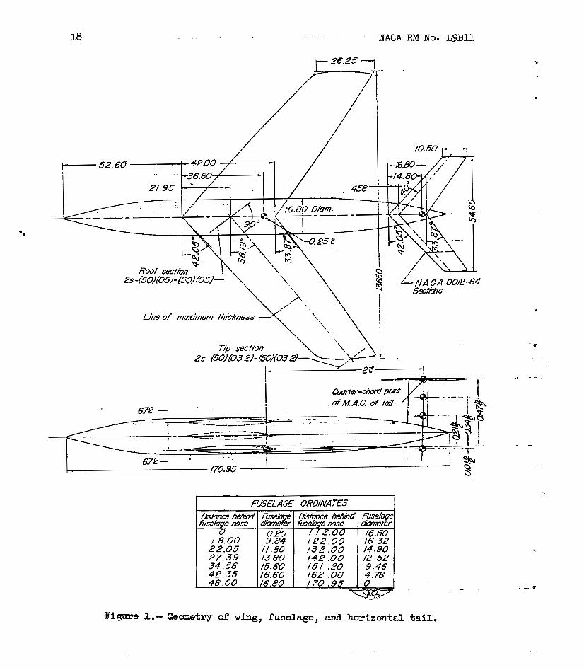
The principle dimeneions of the model are shown in figures 1 and 2. Photographs of the model mounted for testing in the Langley 19-foot pressure tunnel are.shown as figure 3 . The wing, which was of solid steel construc- tion, had smtrical circular-arc airfoil sectioni, an aspect ratio of 3.94, and a ratio of tip chord to root chord of 0.625. A straight line connecting the leading edge of the root and. theoretical tip chords was swept back 42.050.

4 NACA RM No. LgBll Y .
The a i f l o i l sect-lons, W e n normal t o the line of maximum t h i cbess , hail a maximum, t h i c h e s s of 10 percent of 'the chord a t the root and 6.4 percent of the chord a t the t ip. Parallel t o the plane of symmetry t he maximum thiclmess was 7.9 percent of the chord a t the m o t and 5.2.percent of the chord a t the t i p .
The drooped-noee f l aps w e r e hinged on the lower surface and had a chord of approximately 18.4 percent of the wing chord measured parallel t o the plane of symmetry. Two spans were tested: one covering the outboard 60 percent of the wing eemispan, and the other, the outboard 73 percent. They were- constructed 80 as t o provide deflections of Oo, 200, 30°, and 40°.
The round nose, extensible leading-edge flaps were of con8tant.chord and deflection and were tested with spans of 55 percent and 70 percent
of the w i n g semispan. These flapB extended frm' the 0-975-; s ta t ion to b L
the 0.42s and 0.27% stations, respectively, 88 shown i n figure 2. A
nose radius was obtained by w e l d F n g a 5-inch steel tube to the s tee1 f l aps and then f a i r i n g t o give a smooth contour.
1
The t r a i l fng -edge sp l i t f hps used w e r e of m-percent chord and covered the i n b m 50 percent a d s p a n . They were def'lected 600 from the lower surPace of the wing in a plane normaL to the f lap hinge l i ne . For all wing-fuselage ' tests, the inboaml portfon of .each flap, covering 12.4 percent of the wing semispan, was removed.
The stall-control fences, mounted parallel t o the plane of symnetry and with a canstant- height .of 40 percent of the m x i m t h i c h e a s of the root chord (fig. 2) were instal led on the wing upper surface for some of the tests. They extended from the wing l ead ix edge t o the t r a i l i n g edge for all configurations except those involving t h e drooped-nose flaps, in which cme they extended from the f 4 p hinge line t o the wing trailing
edge I n tests with the 0.7% leading-edge f l aps and the 0.752 drooped- b b
nose flaps, the fences were mounted at a distance of 30 peroen-t-of the wlng semispan outboard from the plane of syrmnstry. For all other tests i n w h i c h fences were used, they were mounted 45 percent of the wing semispan outboard of the plane of symmetry.
The fuselage was of circular cross section with a maximum diameter of 40 gercent-.of the root chord and had a f ineness ra t io of 10.2. The section of the fuselage intersected by the wing waa of. constant- diameter and had removable blocks t o permit attachment t o the wing at three ver t ical posi t ions. The fuselage was constructed of laminated mahogany, lacquered, and sanded m o t h .

NACA RM NO- L9Bl.l 5
I
The horizontal tail had the same form as the wlng and an area of 0.16 .that of the wing. The a i r f o i l sections of the t a i l , parallel ta
msasured between the qmxter-chord poFnts of the Xing and tail man aerodynamic chords and parallel t o the plane of synanstq, m8 approxi- mately twice the wing mean aerodynamic chord. The four ver t i ca l positiene of: the horizontal tail a m shown in figure 1 and are given i n percent of wing semispan above the wing chord extended. The tail incidence was measured with reapect to the WFng chord plane and was varied by rotat- the tail about a line normal t o the plane of symmetry and through the quarter-chord point of its mean aemaynamic chord.
- the plane of symmetry, were IIACA 0012-64 se’ctione. The tail length,
TESTS
The tests were conducted In the Langley 19-foot pressure GuTlnel with the a i r compresse& to appmxinrately 33 pound6 per square absolute. A l l t e s t s were made a t a Reynolda number of 6.9 x 1 3;” based on the wing mean aerodynamic chord, and a ach nmber of 0.15. - The Ut , drag, and pitching moment were measured by a ~ i IRLi l”~~s lg recording bslance system through an angle-of-attack range from near
1 zero lift t o begond maximum lift. Stall characterietice were studied by observation of the behavior of wool tufts attached to t he upper mrf’ace of the wing.
ii
RElXJCTION OF DATA
A l l data have been reduced to stasdard nondimsnsianal coeff ic ients and have been corrected for support ta re and Interference eff ecta and f o r air-stream misdinement. The jet-boundary corrections t o the angle of at tack and drag coefficient were calculated f r m reference 4 and w e r e SB
f ol lazs :
The correction to the pitching-mrrment coefficient for configurations without a horizontal tail waa
ac, = 0. OdClC,
and for configurations with a horizontal tail was
All correctione were added to the data.
t
6 NACA RM NO. L m l l
The dawnwaeh asglee were coqputed from the pitching-mment coefficients of the model with an& nithout the horizontal tail. The dynamic-pressure
r a t i o qt/q was determined Pram the r a t i o of tail effectiveness at i
a given angle of a t tack to the effectiveness a t
m T S AND MSCUSSION
tern lift.
The l i f t , drag;and pitching-moment c h ~ c t e r i s t i c s of the wing equipped w i t h various high-lif t &nd stall- control devices are preeented i n figures 4 t o 10. The characterietice of t he various wing-fuelage combinations are preeented in figures 11 to 14. A s- of some of the Important charac.t;eristics of the wing for various configurations is given in tables I and I I . The s t a l l progressians are shown in figures 15 t o 17- To assist In interpret ing the lift=drag variations in terms of power-off' gliding characteristics, contours of canstant gliding speed and constant vertical. ( s w i n g ) speed are superimposed on the l i f t -d rag p o k e of severd configurations and are presented i n f i g u r e 18. ma longi tudiaa l s tab i l i ty charac te r i s t ics of the model equipped with the horizontal t a i l are shown in figures 19 t o 23.
Although some of the data presented herein have 'been reported i n reference 2, they are included f o r the sake of campletenees.
C
Characterist ics of Basic Wing
The plain w i n g and the wing w i t h the sp l i t f l aps exhib i ted poor l i f t , drag, and pitching-moment- chaslacterietice. Both canfigurntiow were found t o have n d i n e a r v a r i a t i o n s of l i f t and pitching moment- with angle of attack and rapid increases i n drag at moderate lift coefficients (fig: 4). m e values of maximum Uf t coefficient were approximately 0.84- and 0.95 f o r the '*in wfng and for the wing with the split flaps, resgectively. The pitching-moment curve for both configurations became sharply posit ive a? the stall began on the outer portions of the wing and then broke in a negative direction as the s t a l l progressed inward toward the root section (fig. 15(a)).
The ef fec t of upper-surface stall-control f ances was quite pronounced. By delaying the onset of-the t i p stall, the fences extended the l i f t curve i n a manner such &B t o increase C h elightly and t o coneiderably reduce the angle of a t t ack fo r ( f i g . 4). The posit ive breaks In t h a pitching-moment curve8 were delayed until m e reached (fig. 4). A more complete investigation o f s t a l l - c o n t r o l fences reported in reference I showed that equally good result8 could be obtained with a much snialler fence, provided it was located a t the wing leading edge.
NACA RM No. LgBll
Leading-Edge Flap Investigation
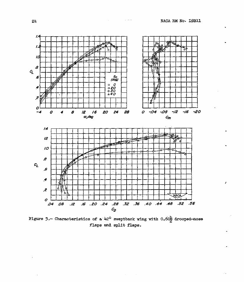
Drooped-nose f b p s . - A considerable increme in & of the basic wing was obtained by the deflection of the drooped-noae f laps , although
large var i a t ime in - were evident throughout the l i f t range- With
the 0.6$ drooped-nose f laps & - t h e s p l i t f l a p , maxim lift coefficients of 1.26, 1.28, and 1.29 were obtained with droopex-nose f lap aeflectione of 20°, 30°, and 40°, respectively (fig. 5 ) . Thud, the amount of deflection within this range appeared t o have l i t t l e ef fec t on the maxfrmun lift. In I
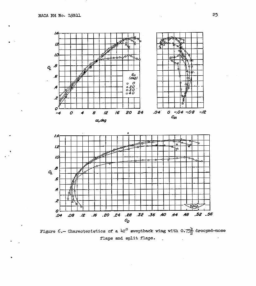
the case of the 0 .79 drooped-nose-f Lap configuration (fig. 6 ) was
substantially the sam as that for the 0.6% configuration at deflections
of 30' and 40° a& s l igh t ly less at a deflection of 20°- In a previoua . investigation (refereme 5 ) of a 43O sweptback w i n g with similar a i r f o i l sections, however, it was found that the values of C decreased rapidly a8 t h e s p a n of the drooped-nose f l a p was reduced belaw O.5&. b 2 As can be seen in figures 4 to 7, the increment In C k due to t he
s p l i t flaps (about 0.10) was the same with the 0.6$ drooped-nose flaps as with the p la in wing, whereas with the 0.7% drooped-nose flaps We
increment was somewhat lager (0.17). Above a lift coefficient of
about 0.5, the -drag coeff icients of the WFng with the 0.7% drooped-nose flaps were appreciably smaller than those of the Xing w i t h the 0.6s
2 drooped-nose f h p s for 'configurat iom both w i t h and d t h o u t s p l i t f h p .
The pitching-mameat character is t ics of the cmfiguratiane erqloying the drooped-nose f h p s were generallg unfavorable, with Large variations
in- occurring throughout the lift range. The typical s t a l l
progressiona presented in ffgure 15 e q h i n these large variations, particulazly a t the angles of at tack at' which a i r flow separation occurs. For the configuration OT s p l i t f laps and 0.6% drooped-nose f b p a deflected 30°' (fig., 5 ) , EL stable break in the pitching-moment curve occurred above a lift coefficient of about O . 7 5 C h . The stall pmgressione show that the e-ed area began Just behind the inboard end of the drooped-nose f laps and progressed inward more rapidly than it progressed outward , thus 'causing a large nestive slope i n the moment curve. At C h the stalled area expanhd rapidly inboard to envelope the en t i r e root section and cause the pitching-moment curve t o break i n a negative direction. For the configurations w i t h
the O.73 tiroopod-nose flapa, both with and without s p l i t f l a p s , a large unstable pitching-momant break a t & was obtained for all f l a p . deflections investigated.
dCm dCL
2 b
G?n dCL
b

8 NACA RM NO. LgSll
These results indicate that for a 420 sweptback wfng the 0 . 7 3 b
drooped-nose flaps appear t o offer eom increases in L/D r a t io s in the higher l i f t range but no advantages over the 0.6% f laps i n . t h e mimum l i f t attainable and are in fer ior from stabil i ty considerations.
b
The maw function of? the upper-suzTace fences was t o reduce the
large variatione in - i n the range up t o by al leviat ing the ' dCL
I spanwise flow towards the t i p s which contributed to e a r l y t i p stalling (fig. 8).
a t e n s i b l e leading-ed8;e f laps . - The value of CLmax obtained f o r the wing equipped with the 0.74 extensible leading-edge flaps but with- out the s p l i t f l a p s was reported in reference 2 t o bs 1.18, which was somewhat greater thansthat- shown herein f o r the 0.7% drooped-nose f laps . The addition of the s p l i t f l a p s t o the wing w i t h the 0.7$ extensible leading-edge flaps, however, m a t e d in a of 1.52 (fig. 9), an increment of' 0.34 as ccrmpamd wfth ap increment of only 0.17 obtained by adding the s p l i t f lap t o the wing w i t h the 0 . 7 9 drooped-nose flape . The maximum l i f t coefficient obtained using the 0.5% exteneible leading-
b
2
edge f l a p s i n conjunction with the s p l i t f l a p s wae 1.35, which is s l igh t ly
&reSter than that obtained with the 0.64 drooped-nose flap6. These values are caparable t o those obtained i n a previoua inveetigation of a wing with similar plan form and leading-edge f h p configuration but incoypo- ra t ing NACA 64,-112 airfoil sections (reference 3) .
a
The pitching-moment character is t ice in the range up t o the s t a l l were generally more favorable than those of the drooped-nose-flap configurations. With the 0.74 extensible leading-edge f laps and a p l i t f laps , the pitching-moment-curve broke i n a slightly posit ive direction a t maximum l i f t , whereaa with the 0 . 5 2 extensible leading-edge flap8
dCnl dc,
z and s p l i t f l a p s - became negative considerably below C h and
a t C h large negative moments were obtained. For this 420 sweptback Wlng-a span' of about 0.6% f o r the extensible leading-edge flaps
probably would supply favorable pitching-mcanent-chaacteriatics withaut
-
b
a large sac r i f i ce i n cLmax'

NACA RM No. LgBll 9
The effect of the stall-control fences w a B similar to that on the drooped-nose-flap configuration. The fences provided more stable moment characteristics in the moderate to high-lift range, 'although for the wing wlth the short-span extensible leading-edge flap this effect was
smll. For the 0.7% extemible flap configuration, however, the slightly positive break of the moment curve at C h was reversed and became slightly negative.
b
m e characteristics of the model dth several flap configurations and with an assumed wing loading of 40 pounds per square foot a r e shown in figure 18. No attempt has been made to account for t he changes in lift due to trinrming of the pitching moments nor for the effects of a fuselage, W i n g gear, nacelles, or other protuberances. Inasmuch 88 this presentation represents a steady state glide, the relative perform- ance of a landing maneuver, which us- involves accelerations, is not specifically indicated. However, t he general effects of the flaps
in a steady glide m e rea- ehom. m e configuration of 0.7& exten- sible leading-edge flaps and split flaps provided. a minimum sinking s p e d of 30 feet per second *ich was the lowest obtained wtth the flapped configurations investigated. At this sinking speed, a gliding speed of approximately 120 miles per hour wa8 obtained. The sinking sped of 30 feet per second is higher than the presently established limit of 25 feet per second reported in reference 6 , although thia could probably be reduced somewhat by decreasing the split-flap deflection. The 0.32 extaneible leadhg-edge fla'ps and t he 0.60- b
2 drooped-nose flaps showed about the same gUde characteristics but
both had higher horizontal and vertical speeds than the 0.7s extan-
2
sible f l a p configuratian. 2
Wing Fuselage Investigation
The wing, equipped with various high-lift and stall-control. devices, was tested in conjunction with a fuselage mounted in high-wing, mid-, and low-wing positions, and the results sunansrized in table I(b)
The addition of a fuselage in any of t h e three vertical psi tions to t he plain wing or wing with split flaps caused no large changes In the wing characteristics (reference 2). A alight increase in C h with t h e high-wing and midwing arranganente and a moderate destabilizfng effect throughout the lift range were obtained.
For the wing with leading-edge devices, the effects of a fuselage
were more pronounced. In the cam of the wing wi th O.% drooped-nose flaps deflected 300, B a i t flapa, and upper-surface fence8 (fig. U ) ,
b

10 NACA RM NO. LgBU
the addition of a fuselage In the high-wing or midwing posit ion caused an increase i n C h of 0.10 even though the inboard 25 percent of the s p l i t f l aps were removed t o a l l o w f o r instaJ.htian of the fuselage. I n addition, above a l i f t coefficient of 1.0 the drag coefficienks were reduced corisiderably with these high" and midwing configurstions. The values'of C b CD obta ineavi th the low-wing posit ion were
about the same aa those obta;ined.without the fuselage but with the s p l i t f l a p s . ex-tending in to the plana of symiet4.. The higher values
Of obtained with the- high-wing and midwing positions probably
.
resulted--f'rom the action of the fuselage in delaying the root s t a l l t o a higher angle of attack. The pitching moments of them configurations, however, became unstable near i n contra8 t to the s tab le moments obtained wi th the low-wing and fuselage-off conditions. Reference t o the stall studies of figure 16 indicates that in the high-wing and midwing positions, the fuelage prevented the stall f m enveloping the m o t sect ions unt i l after the t ips had stalled, thus producing the unstable pitching-mment~chacteristica. W i t h the low-wing configuration, however, some root stalling occurred and a small etable pitching moment
. . .
at C h resulted. .. . . . . . . . . . . . . . . . . . . . . . . . . . - . " . .
The effecta of the %selage on the.lift and pitching-moment
?haracteriakica of. the w i n g with 0.60- b drooped-nose flaps with split
flaps off were about the i a i G a s the"effe&-tFZi-i;h s p l i t f h p e .On. In the l o w - w i n g positi~%~-however, an unstable pitching moment--- a t C b waa obtained f o r the configuration xith split f l aps off' although t h i s was preceded by .a large s t a b l e v e i a t i a n near
2 . " . - r -
. . . . . . . .
(fig. 12). elkax
The effecta on the lift and drag coefficients of adding a fuselage to the wing w i t h 0 . 5 9 extemible leawg-eage f h p s a-m~ s p ~ . t f7apB were similar t o thase f o r the 0.6 drooped-noae-fhp configuration, b
2 except that in the high-wing poeitian the increment Fn & was
considerably larger an& resulted in a maximum l i f t c o e f f i c i e n t of 1.52 (fig. 13) - The pitching-momen-tvariaticma a t C f o r the high-wing
and midwing positiong, however, were stable in contra& t o the unstable variations obtained ~ 5 t h the itrooped-nose f lap . This e f f e c t - i s explained by a study of the atall progreaaions of figure 17, which shows that-the outboard wing sect ions for these configuratian~l remained unstalled
pitching-moment variation was obtained a t a l i f t coeff ic ient juet under * tha t of C The l i f t continued to increase t o a second maximum at a very high angle creattack, however, and at this point-a- large unstable pitcMng-mnmFmt variation occurred. Rsference to figure 17 shows tha* this in s t ab i l i t y i s associated w i t h the onset of t i p s t a l l i n g .
2
L
throughout the l i f t A g e . . . For..the low-wing position, a large stable
Lmax' . . . . . ...

NACA RM No. L9BU n "
. For the configuration with the 0-7% extensible leading-edge flaps
and split flaps, the addition of 'the fuelage in either the high-wing or midwing positions did not appreciably alter the value of but
did result in a amaU decrease drag coeff icienq (fig. 14). With the low-wfng position, the value of C was actuaily reduced about 0.10 from that obtaFned with the fusekge off. However, Fn reference 2 Etnd in unpublished data it w a s shown that for this same configuratioa, but with s p l i t flaps off , the value of C b w&s increased by increments of 0.15 to 0.20 by the Elddition of a fuselage in any of the three vertical positions. The f Fnal break in the pitching-moment. curves was in an unstable directicm for a l l wing poaitione, although for the low-wing - position there'waa a shEtrp stable break Fmnmediately preceding C
b
cLm,x
L a x
Lma;x'
!The effect of upper-surface f ences was found to be about the same as that f o r configurations without the fuselage, and the data have therefore not been Included in t h i s paper.
In general, the effects of a fuselage on t h e various wing configurations tested were found to be sFmilar to those obtained in previous tests of an NACA 6 4 1 - n ~ wing of ~ F m i l a r plan form (reference 3)
Horizontal Tail Investigation
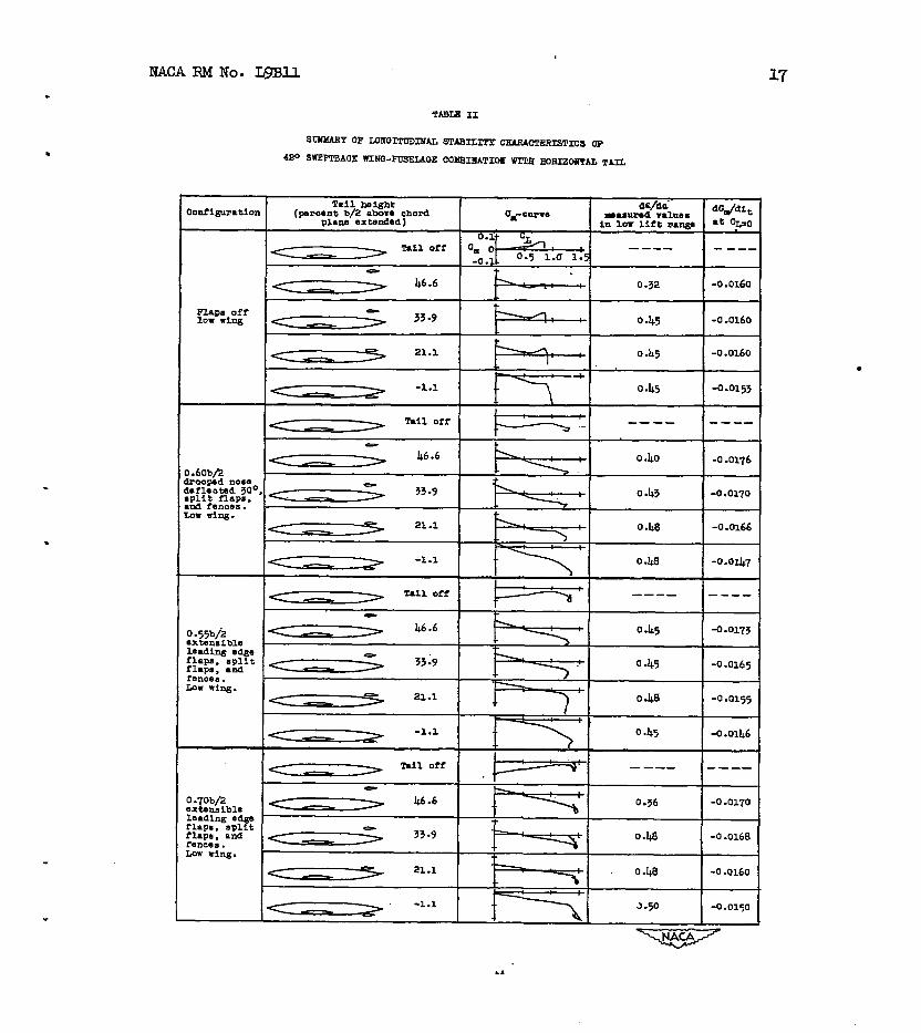
A summary of the longitudinal staMlity characteristice of t he low-wlng-fuselage combination with a sweptback horizontal tail is presented in table 11. Also included is the tail effectiveness
parameter 5 at cl; = 0 which was used as a basis Fn determining qt/q.
In figures 19 to 22y data are presented showing the lift and pitching- moment characteristics of the combination dth the tail located in several vertical positions and with various leading-edge devices on the wing. In figure 23 is shorn the variation of neutral-point location wim lift coefficient for the various configurations tested.
dit
It can be seen that in the l o w to moderate lift range the greatest degree of stability was obtained w i t h t h e horizontal tail in the high positions. This effect is the result of the relatively l o w values
de of - dcL' dynamic pressures at the tail equal to free-stream dynamic pressures, and (as shown in table II) relatively high values of - dc,
dit which indicate little fuselage interference. Conversely, in the rangd near the stability was the greatest f o r the loweet tail position. w i t h the exception of the lowest tail position inGestigated, t h e contri- bution of the tail to the stabilitg in the s t a l l i n g range was ara8l.l.
12 NACA RM No. LgBU
The dynamic-pressure r a t io s shown i n figures W-.to 22 Indicate that the tail i n the l o w posit ion was first enveloped by the wing wake at low angles of attack and then a t angles of at tack near thoee for i t emerged from the wake which rose with respect to the wing chord plane extended. The angle of at tack at which the tail entered the wake became progressively greater' as the tail height was increaeed. The favorable effects on of the wing wake being located above the t a i l i n i ts lowest poeition probably explains the large contribution to s t a b i l i t y by the tail in this position.
doc
The influence of the wing s t a l l progression on the s t a b i l i t y ,contributed by the tail appemed t o be s l igh t . In the high-lift range, the effect ive values of " at the tail f o r the unfhpped wing, where stalling began st' the t ips , were about the same as f o r the flapped configurationa, where initial stalling occurred near the root.
The addltion of the 0.69 drooped-nose flaps together wlth the s p l l t b
f b p s resulted in a slight rearward s h i f t of the neutral point a t lox lift coefficients and EL slight forward shift a t higher lift coefficients ( f ig . 23). The addition of either the 0.53 o r the 0.7% extensible leading-edge f l aps and s p l i t f laps , on the other hand, resulted i n a slight forward e h i f t of the neutral point- which wa8 probably caused by %he increased wing area ahead of the center-of-gravity poeitian under consideration.
b b
In general, the ef fec ts of the various tail positions and the high- lift and stall-control devices on the longi tudinal s tabi l i ty character is t ics of the model were similar to thoee obtained fur a model with a eimilar plan form but having NACA 641-n~ airfoi l sect ions ( reference 7).
COmCLUSIOMS
From the r e su l t s of tests to determine the effects of .h igh - l i f t and atall-control devices, a fuselage, and a horizontal tail on a wing sweptback.42O a t the l e a d i q edge and having symmetrical c i r c u h r - a r c a i r fo i l sec t ions , the following conclusions have ,been dram:
1. The maximum l i f t of the wing was not . c r i t i ca l ly dependent upon either the span or deflection of the drooped-nose f l aps within the f lap span range OF 0.60 to 0.75 semi.span and ~e deflection range of 200 to 40°. The pitching-moment character is t ics , however, varied with change i n span o r deflection. The maxW lift- and p i tching-moment character is t ics with the extensible leading-edge flaps varied coneid- erably with a change i n f l a p span from 0.33 to 0.70 eemiepm.
M
c
2. For the configurations with drooped-nom flaps or exteneible leading-edge flaps, the addl tian of s p l i t flaps resulted in incrementa
* in maximum lift coefficient up t o 0.19 and 0.34, respectively.
3. The use of the leading-edge devices in conjunction with half- span split f lapa resulted Fn considerable increases in the maximum lift coefficient, but the extensible leading-edge 'flaps produced more desirable pitching-moment chazacteristics than did the drooped-nose flaps.
4. Stall-control fences generally had a stabilizing .influence on the pitching-moment chmacterietics in the moderate to high-lift range-
5. The addition of a fuselage in the high-wing or midwlng poeitiona provided increaaes in the m m i m u m lift coeff lcient up to 0- 2 for most configuratione but wa8 often detrimental to the pitching-moment characteristics.
6 . The configuration w i t h 0.55 aemispan extensible bading-edge flaps, split flaps, and high-uing position provided a maximum lift coefficient of 1.52 and stable pitching-momnt characteristice. These results are comparable to the lift and mcBllsnt characteristics obtained for a wing w i t h similar plan form and configuration but incorporathg mACA 641-u~ airfoil sections.
7. The static l ong i tud lnd stability provided by the horizanM tail was the greatest for high-tail positims a t lar angles of attack a d for hw-bil positions at high @ea of attack. - Langley Aeronautical Laboratory
National advisory Committee for Aeronautics Iangley Air Force Base, Va.
14 NACA RM NO. L D l l
1. Weil, Joseph, Comiearow, Paul, and Gaodeon, Kenneth W. : Longitudinal . . . . "
Stability and Control Characteristics of an Airplane Model Having a 42.80 Sueptback Circular-Arc WFng with Aspect Ratio 4.00, Taper Ratio 0.50, and Sweptbgck .Tail. Surfaces. NACA RM No. ~ 7 ~ 2 8 , 1947.
2. Neely, Robert H., and Koven, William: Low-Speed Characteristics in Pitch of a 4 F Sweptback Wing with Aspect- Ratio 3.9 and Circular- Arc Air fo i l Sections. NACA RM No. L7E23, 1947.
3. Graham, Robert R., and Conner, D. William: Investigation of Eigh- Lift and .Stall-Control Devices on an NACA 64-Series 4 2 O Sweptback Wing w i t h and without Fuselage. MACA RM No. L7GO9, 1947.
4. Eisenetadt, Bertram J. : Boundary-Induced Upwaah f o r Yawed and Swept=Back Wings in Closed Circular Wind Tunnels. . .NACA TN No. 1265, 1947. . .. .
5. Guryansky, Eugene R., and Lipson, Stanleyi". Effect of €&h-Lift. Devices on the Longitudinal and Lateral Characterietics of a 45O bheptback Wing with Symmetrical Circulas-Arc Sectians. NACA RM No. L8DO6, 1948.
6 . Gustafson, F. B., and O'Sullivan, William J., Jr. : The Effect of Hi& Wing Loading an Landing Technique and Distance, with Experimental Data for the 3-26 Airplane. NACA ARR No. LkKO7, 1945
1
7. Spooner, Stanley H., and Martins, Albert P . : Longitudinal Stdbility Characteristics of a 42O Swep back W i n g and Tail Cambination at a Reynolds Runfber of 6.8 x I & . NACA RM No. L6E12, 1948.
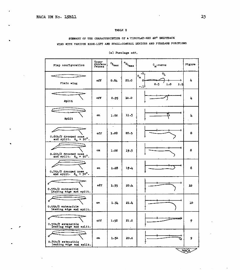
TASLES I
8 SlX?URY OF THE CEARACTERISTICS OF A 'CIRCULAR-ARC 42O SWEFTBMK
KTNQ NITH VARIOUS BIffH-LIFT STALL-COWTROL EWICES AIfD FUSEIAGE POSITIONS
- acLGlnx
21.0
I C,-cuTve
F Flap configuration
Plain wiw
" Off I Ooa4
off 16 -0
11.5 i" 1.28
1.26
1.20
20.5
19.3
19 -4
err
on
on
0.60b/2 drooped nose and s p l i t . Gin = 30'.
0.60b/2 drooped nose and sp l i t . en = 30°.
0.75b/2 drooped nose and s p l l t . a,, = 30'.
off 20 .L
21.4
21.2
1-35
O.55b/2 extensible leading edge and s p l i t .
0. Ob/2 extensible Ieadlng edgs and s p l i t <
c c
9 20.6
- O.7Ob/2 extensible leading edge and split

16
TABLe 1.- Concluded
.
Cm-curve
21.4 l1 b 0.60b/2 drooped nose I and s p l i t . 6n = 30'. I 1 - I 19 .o l1 k= on 10-
ring on 10-
ring 1.25
- 1.52
1.25
- 1.52
I 0.60b/2 droowd nose and sg11 t. om = 300
0.60b/2 droowd nose and sg11 t. om = 300 +
0.55b/2 extensible l e a d i n g edge and s p l i t ,
0.55b/2 extensible l e a d i n g edge and s p l i t , I I I
I I I
I I
I I I A I
20-2 4 0.70b/2 extenaible
leading sags and a p l i t . J.
20.6 14 +-
I- 22.6 14 1- 0.70b/2 extsnaible leading edge and split.
. NACA RM NO. Wll
TABU I1
< . > Tall off
0 I + I
46.6 [ 0.32 -0.0160
-0 -0160
-0.0160
-0.0153
-0.0176
-0.0170
-0.0166
-0.047
""
-0.0165
-0.0155
-0.01b6
""
-0.0168
-0.0160
-0.0150
18
Lhe of muximum fhickness
.
z
. -
FLEELAG€ ORD/NATES &kme Mkw'
1 8.00 0
&meter &&@e m e &new fuse1uge mse Fuse1up DIM^ Le&d fi-
020 1 12-00 16.80 9.84 /22 .OO 16.32
22.05 11.80
4.78 /62 .OO 16.60 42.35 9.46 /5/ .20 15.60 34.56 /2.5.2 142 .OO 13.80 27.39 14.90 132.00
48.00 16.80 170 .95 0 "
.
... d
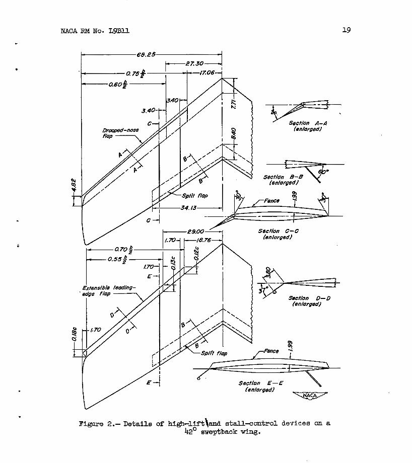
NACA RM NO. LgBll
-y-=+ Section A-A
(enlargedl
Sectfun B - B (enlarged1
E -
&tensfbfe leading- * sdpe flap
a i
Sscthn C- C (enlarged)
Splfi flap
Section E- E (en forged1 v
Figure 2.- Details of hi&-lift\and stall-control de~ices an a 42' eweptback wing.

a
lrTAcA RM No.
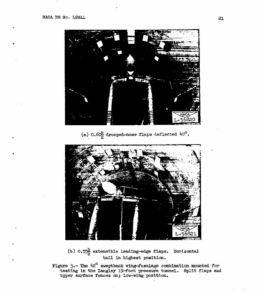
(b) 0.5% erkansible leabing-edge flaps. Horizontal tail fn highest posttian.
Pigure 3.- The 42' sweptbwk win@uselage cabination mounted f o r testing in the Iangley 194oot pres- tunnel. Split f laps esd upper surface f a c e 8 an; low-wlng position.


-4 0 4 8 12 16 20 24 28 cc, d g
0 .04 .08 .I2 ./6 20 24 .28 .32 -36 .40 .44 .48 3 2 .56 CD
Figure 4.- Characteristtcs of a 42' sweptback wtng dth and without split f laps and uppelL8urfaoe stall-control fences. ,
-
24
-4 0 4 8 12 I6 20 24 28 E,&
/.4
12
1.0
.8
.6
.4
.2
0 0 4 .08 ./2 ./6 .20 .24 .28 .32 .36 .40 *44 -48 -52
ci?
J
Figure 5.- Characteristics of a. 4 2 O sweptback w i n g with 0.6e drooped-nose
flaps and split flaps.
NACA RM NO. LgBll 25
Figure 6.- Wacte r i s t i c s of a 42O Bweptback wing wlth 0.79 droo@d-noee
flape and s p l i t fh-ps. .
2

-4 0 4 8 12 i6 20 2+ 28 .08 -04 0 -.04 -.08 -.I2 -.I6 =*&7 Gm
12
LO
.8
.4
.P
0
72
-.4 0 .04 .OB .I2 ./6 .20 .24 .E8 3 2 .36. 40 .44 .48 .52 36
GD
Figure 7.- Characteristics of a bo sweptback w i n g with 0.6% and 0.7% droaped-noee flaps with and without s p l i t f l a p s . 6, = ' 30'.
.
.

D ~ " n 0 S e - flap spon Fences
o 0.60 b/2 off n -75 b/2 ot f A .6Ob/Z on 0 .75b/2 on
CY
.08 .I2 ./6 .20 2 4 -28 .32 .36 .40 .44 .48 .52 56 GD
Figure 8.- Cha3.acteristics of a 42O sweptback wing w i t h 0.6* and 0.7% drooped-noae flap8 with and wfthout upper-eurface fences. S, = 30°. split flaps on.
.
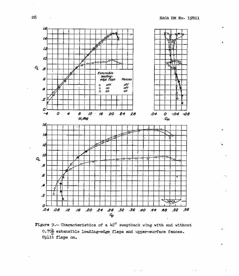
28 . . NACA RM NO. LgBll
""""
.04 .OB ./2 ./6 .20 .24 28 .32 .36 .40 44 -48 .52 .56
%
.
edge fiups Bnces
-4 0 4 8 12 I6 20 24 e, olpp
Figure 10.- Characteristics of -a k 2 O aweptback wlng w i t h and wlthout 0.5% extensible 1eadt-w flaps a ~ d uppez-surface fences. Split f laps on.
-I 0 4 8 /2 16 20 24 GW
.
.04 .08 . e ./6 2 0 2 4 28 .32 -36 $0 #4 .48 .52 .56
Go
Figure 11.- Effects of wtng-fuselage position on the characteristics of a 42' 8 m p t b ~ ~ c k wing Kith 0.6& droopd-llose flap, split flaps, and upper-surfaces fences. 6, = 30 2, .

-8
-6
.4
G -2
0
-. 2
-.4
0 .04 .08 . f 2 -.I6 .20 2 4 28 -32 36 .40 .44 .48 -52 Go -
Figure 12.- H f e c t s of winefuselage posit ian on the characteristics of a 42' sweptback wing with 0 .69 drooped-aose flaps and upper-8~mface fences. = 30°.
32 NACA RM NO. LgSU
8
Figure 13.- BfectB of wingdue lage position Q T ~ the characteristice of a 42' meptback wing with 0.5% extensible lead-dge flap,. Bplit 'flaps, and u p p e ~ u r f ' a c e s fences.

16
M
12
110 Wing- fimlage paiffon
&
.6
-4
.2
0 Fusefags off
0 .08 .I,? ./6 .20 .24 28 .32 -36 -40 .44 -48 32 .56
c, 14.- H f e c t s of wingaselage position on the chmacter ie t ics meptback wlng w f t h O.7& extansible lekin&Qe flap, ~ p l i
upper-surface fences. 2
of a t flaps,

34
a
(a ) Flaps off . (b ) 0.6$ drooped - (c ) 0.6& drooped nose 2
no88 flaps deflected flaps deflected 30' 30°. Split .flaps On. Split flaps apd upper . - f
aurface fences on. Figure 15.- st-all ing characteristics of a 4 2 O eweptback wing.

NACA RM NO. LgBll 35
(a) LOW wing. (c) €ri& wing.
Figme 16.- Stalling characteristics of a 42O sieptback wing-fuselage combination with 0.6% drooped nose flaps, split f laps , and upper surface fences.
..
36 MACA RM NO. LgSll
(b ) Midwing. (c) High wing.
Figure 17.- StaJ l i ng characteristics of a 42' meptback wing-fuselage combination with 0.5% extensible leadin@;-ed.ge f l a p s and split flape.
.

. . . ..
l a L
1.6
1.4
/.a
1.0
.8 CL
.6
.4
.P
0 0 .04 .08 .I2
. . .. . . . . . .. .
LP
.8
d
, I2
.08
.04
0 cm
-. 04
: 08
-. I2
-.I6
-.PO
-. 24
24
16
E,- 8
0
-8
10
.8
.6 CL
.4
.P
0
SP
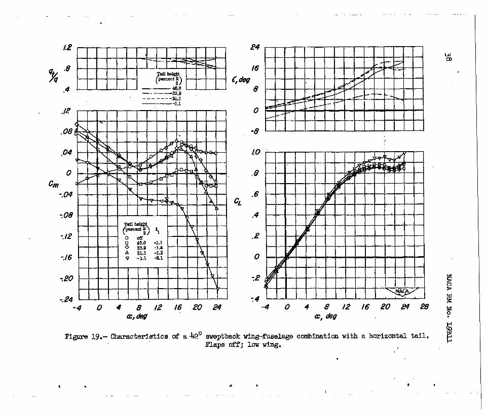
Figure 19.- Characteristics aP a -42' meptback wing-fiselage combinatIan with a horizontal tail. Flaps OFP; low ving,
I . .I I
. . . . . . . .
.. .
1.4
1.0
.8 c;
.6
.4
.P
0
-.2
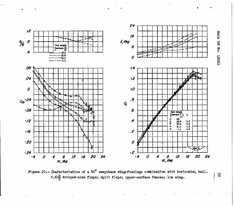
Figure 20.- Characteristics of a k2° .mptbmk *fuselage combinatIan w t t & horizontal tal". 0.6$ drobped-noee f laps; split f laps; upper-surface femme; low wing.
. . . .. . . . .
- . . . . . . . . . . . . . . .
L2
.8 %
.4 - 48.6
GL
14
12
LO
.8
.6
.4
.i?
0
TP -4 0 4 8 tP t6 PO 24
a, w
4 I I
. . .. . .

I .
L2
% -8
,4 4.0.6 33.0
--a1 1.1
"_ ""
-"-
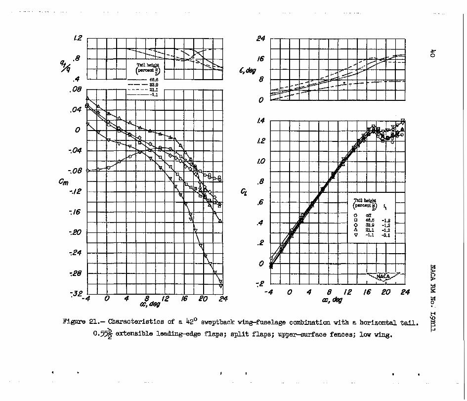
Figure 22.- Characterhtics of a 42' sweptback win@uaelage ccrmblaatlcm with a horiecmtaJ. tall. 0.7% extensible lead*&ge flaps; s p l i t f laps; uppelLsurface fences; low KLng. b

Tail height (percent b/2)
46.6 33.8 21.1 -1.1
1.0 "
"" -"
.8
.6 Cf
.4
.P
0
20 30 40 30 40 50 PO 30 40 50 30 40 50
Neutral poM location, percent Z
I . I
. .. . .. . . .