Embed Size (px)
Citation preview
NASA/TM--2002-211569
U.S. ARMY
ARL-TR-2748
GT-2002-30368
RESEARCH LABORATORY
Self-Recirculating Casing Treatment Concept
for Enhanced Compressor Performance
Michael D. Hathaway
U.S. Army Research Laboratory, Glenn Research Center, Cleveland, Ohio
July 2002

The NASA STI Program Office... in Profile
Since its founding, NASA has been dedicated to
the advancement of aeronautics and spacescience. The NASA Scientific and Technical
Information (STI) Program Office plays a key part
in helping NASA maintain this important role.
The NASA STI Program Office is operated by
Langley Research Center, the Lead Center forNASA's scientific and technical information. The
NASA STI Program Office provides access to the
NASA STI Database, the largest collection of
aeronautical and space science STI in the world.
The Program Office is also NASA's institutional
mechanism for disseminating the results of its
research and development activities. These results
are published by NASA in the NASA STI Report
Series, which includes the following report types:
TECHNICAL PUBLICATION. Reports of
completed research or a major significant
phase of research that present the results of
NASA programs and include extensive data
or theoretical analysis. Includes compilations
of significant scientific and technical data and
information deemed to be of continuing
reference value. NASA's counterpart of peer-
reviewed formal professional papers but
has less stringent limitations on manuscript
length and extent of graphic presentations.
TECHNICAL MEMORANDUM. Scientific
and technical findings that are preliminary or
of specialized interest, e.g., quick release
reports, working papers, and bibliographiesthat contain minimal annotation. Does not
contain extensive analysis.
CONTRACTOR REPORT. Scientific and
technical findings by NASA-sponsored
contractors and grantees.
CONFERENCE PUBLICATION. Collected
papers from scientific and technical
conferences, symposia, seminars, or other
meetings sponsored or cosponsored byNASA.
SPECIAL PUBLICATION. Scientific,
technical, or historical information from
NASA programs, projects, and missions,
often concerned with subjects having
substantial public interest.
TECHNICAL TRANSLATION. English-
language translations of foreign scientific
and technical material pertinent to NASA'smission.
Specialized services that complement the STI
Program Office's diverse offerings include
creating custom thesauri, building customized
data bases, organizing and publishing research
results.., even providing videos.
For more information about the NASA STI
Program Office, see the following:
• Access the NASA STI Program Home Page
at http:llwww.sti.nasa.gov
• E-mail your question via the Intemet to
• Fax your question to the NASA Access
Help Desk at 301-621-0134
• Telephone the NASA Access Help Desk at301-621-0390
Write to:
NASA Access Help Desk
NASA Center for AeroSpace Information7121 Standard Drive
Hanover, MD 21076

NASA/TM--2002-211569
U.S. ARMY
ARL-TR-2748
GT-2002-30368
RESEARCH LABORATORY
Self-Recirculating Casing Treatment Concept
for Enhanced Compressor Performance
Michael D. Hathaway
U.S. Army Research Laboratory, Glenn Research Center, Cleveland, Ohio
Prepared for the
Turbo Expo 2002
cosponsored by the American Society of Mechanical Engineersand the International Gas Turbine Institute
Amsterdam, The Netherlands, June 3-6, 2002
National Aeronautics and
Space Administration
Glenn Research Center
July 2002
Acknowledgments
My thanks to Ms. Sonia Ensenat for her early efforts in support of this research and to Dr. Anthony J. Strasizar
and Dr. Edward M. Greitzer for their efforts in suggesting and initiating this research effort.
NASA Center for Aerospace Information7121 Standard Drive
Hanover, MD 21076
Available from
National Technical Information Service
5285 Port Royal RoadSpringfield, VA 22100
Available electronically at http: / / gltrs.grc._aasa.gov/GLTRS
SELF-RECIRCULATING CASING TREATMENT CONCEPT
FOR ENHANCED COMPRESSOR PERFORMANCE
Michael D. HathawayVehicle Technology DirectorateU.S. Army Research Laboratory
Cleveland, Ohio 44135
ABSTRACT
A state-of-the-art CFD code (APNASA) was employed in a
computationally based investigation of the impact of casingbleed and injection on the stability and performance of amoderate speed fan rotor wherein the stalling mass flow iscontrolled by tip flow field breakdown. The investigation was
guided by observed trends in endwall flow characteristics (e.g.,increasing endwall aerodynamic blockage) as stall isapproached, and based on the hypothesis that application ofbleed or injection can mitigate these trends. The "best" bleed
and injection configurations were then combined to yield a self-recirculating casing treatment concept. The results of thisinvestigation yielded: 1) identification of the fluid mechanisms
which precipitate stall of tip critical blade rows, and 2) anapproach to recirculated casing treatment which results inincreased compressor stall range with minimal or no loss inefficiency. Subsequent application of this approach to a high
speed transonic rotor successfully yielded significantimprovements in stall range with no loss in compressorefficiency,
INTRODUCTION
The current trend toward increased pressure rise per stage
and increased blade aerodynamic loading tends to reduce thestable operating range of compressors. To provide adequatestall margin the compressor may operate away from theoptimum efficiency point. Alternatively, methods may be
devised to extend the stable operating range of the compressor.Over the last 30 years various forms of casing treatment havebeen employed for enhancing compressor stall range, generallythough at the expense of compressor efficiency (e.g., Koch, andSmith, 1968a and 1968b, Prince, et al., 1974, Janssens and
Chedozeau, 1979, Takata and Tsukada 1997, Crook, et al.,
1993).Some modern casing treatment concepts utilize the
compressor static pressure rise to provide for a recirculation ofhigh-pressure fluid from the rear to the front of a compressorrotor through a path contained within the compressor casing(Koff, et al., 1994, Hobbs, 1995, Nolcheff, 1995). The high-
pressure fluid is then reinjected at the casing to energize the lowmomentum fluid in the compressor endwall that contributes tocompressor stall range limitations. Such recirculated casing
treatment concepts have shown promise for providing thegreatest stall range capability with minimum decrement tocompressor efficiency of any previous casing treatment
concepts, however, for modern well designed compressors theystill result in an efficiency penalty.
The genesis of the research reported herein was based on:1) Recognition that there is still room for improving the
effectiveness of casing treatments while reducing or eliminatingtheir detrimental impact to compressor performance, 2) Avalidated capability of state-of-the-art computational fluid
dynamic analysis codes to provide reasonably accuratepredictions of compressor rotor endwall flow fields, and 3) Abelief that improved understanding of the compressor endwallflow phenomena which limit compressor stall range will lead toimproved effectiveness of recirculated casing treatments. As
such, the goal of this research program was to develop animproved casing treatment concept based on a "first principals"understanding, as derived from state-of-the-art CFD, of endwall
flow phenomena which limit stall range.To achieve this goal a state-of-the-art CFD code
(APNASA, Adamczyk 1995) was employed in acomputationally based investigation of the impact of
NASA/T_2002-211569 1

independentcasingbleedandinjectionon thestabilityandperformanceofamoderatespeedfanrotorwhereinthestallingmassflowwascontrolledbytip flowfieldbreakdown.Thisinvestigationwasguidedbyobservedtrendsin endwallflowblockageasstallis approached(Smith,L. H., 1970,Koch,1981,Kahlid,1994,Suder,1997,Kahlid,etal.,1998,Cho,D.L., 1995),andbasedon thehypothesisthatapplicationofendwallbleedorinjectioncanmitigatethesetrends(KochandSmith,1968a& 1968b,Smith& Cumpsty,1982,Crook,etal.,1993).Thebestbleedandinjectionconfigurationswerethencombinedtoyieldaselfrecirculatedcasingtreatmentconceptthat provideda significantincreasein stall rangeandcompressorefficiencybyreducingthecasingendwallblockage.Subsequentapplicationof this approachto a highspeedtransonicrotorsuccessfullyyieldedsimilarimprovementsinstallrangewithnolossincompressorefficiency.
NOMENCLATURE
P Static pressure, PaPt Total pressure, Pa
T t Total temperature, °K
Uti p Rotor tip speed, m/secV Velocity, m/seca Area, m2
m Mass flow rate, kg/sec1Tlchoke Choke mass flow rate at design speed, kg/secr Radius, m
cz Pitch angle, Deg.
]3 Absolute flow angle, Deg.5' Ratio of specific heats
fl Density, kg/m 3
co Fractional loss in dynamic pressure
Subscripts
1 Bleed port2 Injection portabs Absolute flame of reference
c Flow path casingn Normal componentt Rotor blade tipx Axial component
COMPUTATIONALLY BASED STUDY
A computationally based study of various casing bleed andinjection configurations was performed using the AveragePassage code (APNASA) developed by Adamczyk, 1985.
APNASA is a 3D time-averaged Navier-Stokes code developedfor multistage compressor analysis. For these simulations theCMOTT k-e turbulence model was used (Shih, et al., 1995 &1996). The simulations were of an isolated blade row using an
axisymmetric mass flow boundary condition (Shabbir. A., et al.,
1997) to simulate casing bleed and injection. The upstream
boundary condition was prescribed at standard day inletconditions with 5% boundary layer thickness, based on span, onboth endwalls. The downstream hub static pressure was set and
adjusted in steps to develop a prediction of the rotor speed linefor various casing bleed/injection configurations. Convergencewas deemed to be achieved when the mass flow rate, pressure
ratio, efficiency, and number of separated points remainedessentially constant with increasing iteration count.
As stall is approached the number of separated points in theflow field and other flow field parameters may vary as afunction of iteration count. However, the simulation approaches
a limit cycle in which the peak-to-peak amplitude of the flowfield differences does not grow with increasing iteration count.Away from stall the convergence is well behaved with little or
no variation with increasing iterations. The predicted stall pointwas judged to be the last stable condition prior to incurring, fora fixed hub static pressure, a continual drop in mass flow rate
and pressure ratio with increasing iteration count.The ability of the APNASA code to predict the stalling
mass flow rate for an isolated transonic rotor (R35) has beendemonstrated by Van Zante, et al. (1999), see Figure 1. VanZante, et al. concluded that accurate prediction of the stable
operating range requires careful attention to grid resolution nearthe casing. Also shown in Figure 1 is a comparison of themeasured and predicted stalling mass flow rates for thetransonic rotor studied herein (R67). Though the question still
remains as to whether the code can adequately predict stall forany rotor, it was deemed reasonable to expect that if the codepredicts an improvement in stall range that such would be
realized experimentally, though perhaps to a different degree.A moderate speed fan rotor was selected for the
computationally based investigation of the impact of casingendwall bleed and injection on rotor performance. The fan rotor
had 18 blades, an inlet tip radius of 28.13 cm, a hub-tip radiusratio of 0.426, an aspect ratio of 2.75, a tip solidity of 0.6, andan axial chord of 5.87 cm at the tip and 5.82 cm at the hub. Therotor tip clearance gap was modeled (by enforcement of
periodicity across the tip gap) at 6.8% of tip axial chord (3times the design clearance) to assure that the tip flow fieldwould control the stall point. Based on simulation results at
8750 RPM, the choking mass flow rate at that speed is 38.995kg/sec based on simulations, the blade tip speed is 258 m/sec(846 ft/s), the total-to-total pressure ratio is 1.22, and theadiabatic efficiency is 87.3 %. The mesh size used for thesimulations of the moderate speed fan is 162 axial x 51 radial x
55 tangential nodes with 10 cells in the rotor tip clearance gap.Though this fan performance is not commensurate with that
of modern fans, as a representative tip critical flow fieldgenerator, this fan case was considered suitable for investigatingthe benefits of casing endwall bleed and injection. To assess thegeneral applicability of the "lessons learned" from the moderatespeed fan simulations, subsequent simulations of the "best"
candidate casing treatment would be evaluated on a high-speedfan rotor with good performance (R67).
NASA/T_2002-211569 2

2.00 _
1.95 --
1.90 --
1.8.5
.c, 1.80 --
1.75
_,7o-o _a- 1.65
_16o-
1.55
1.56
1.45
1.40 '0.65
-I- R35 Experimental Data _ vanz.ante, et _1., 1999 O --
R35 APNASA Prediction .J _._
X R67 Experimental Data Strazisar, et al., 1989R67 APNASA Prediction
zR67 100% Speed _ --
, , , I .... I .... I .... I ,--, , , I .... I .... "/,
0.70 0.75 0.80 0_5 0.90 0.95 1.CO
Mass Flow Rate/'Choking Mess Flow Rate @ 100 % Speed
Figure 1 Comparison of predicted and measured stallingmassflow rates for two transonic rotors.
The investigation was guided by reported observations(Smith, L. H., 1970, Koch, 1981, Kahlid, 1994, Suder, 1997,Kahlid, et al., 1998, Cho, D. L., 1995) that endwall
aerodynamic blockage accumulates rapidly as a fan/compressorapproaches stall. The accumulation of low momentum endwallfluid is exacerbated by the incoming low momentum "boundarylayer" fluid adjacent to the endwall, blade/endwall flow fieldinteractions, shock/vortex interactions, shock/tip-leakage-jet
interactions, radial migration of low momentum fluid to theendwall, etc. It was hypothesized that directly controlling thelow momentum producing mechanisms would reduce the rate of
accumulation of endwall blockage thereby improving rotorendwall performance and as a result increasing fan/compressorstall range.
An investigation of the impact on compressor performance
of various bleed and injection locations was thus conductedusing computational simulations including a model forsimulating casing endwall bleed and injection. The uncoupled
bleed and injection cases were simulated with the bleed andinjection port mass flow rates fixed at nominally 1% of thecompressor mass flow rate, and the axial extent of the portsfixed at 10% of rotor tip chord. This investigation attempted to
simulate the benefits of using endwall bleed to remove lowmomentum fluid near the endwall, thereby reducing endwallblockage. The benefits of injection were also simulated basedon using high relative-total-pressure fluid to "energize" low
momentum endwall fluid, thus reducing endwall blockageaccumulation. The best candidate bleed and injectionconfigurations were then simulated in a "coupled" fashion
whereby the low momentum fluid bled off the casing endwallwas recirculated upstream to supply fluid for the optimuminjection configuration. It was envisioned that relying on thepositive static pressure gradient across the rotor to self
recirculate the low momentum fluid bled from the casingendwall to supply high relative total pressure fluid to theinjection point would provide performance benefits from bothbleed and injection. This is not a new concept as there is are
existing patents (Koff, et al., 1994, Hobbs, 1995, Nolcheff,
1996) for such a casing treatment concept. The self-
recirculating casing treatment concept reported hereinadditionally provides:
1) A description of the methodology for identification
and direct control of the most significant endwallblockage producing mechanisms limiting bladeendwall performance (efficiency and stall range), and
2) Implementation of discrete single-pass recirculation toprevent continuous recirculation of high entropy fluid.
The rationale for determining the axial extent of the bleed andinjection ports as well as the recirculated mass flow rate will bedescribed later in the Results and Discussion.
As will be shown herein, directly controlling the fluidmechanisms producing endwall blockage results in a decreasein endwall blockage production and a consequent predictedimprovement in both stall range and efficiency. These predicted
performance improvements are a result of a CFD basedfundamental understanding of the endwall fluid mechanismsmost important to control, and how best to configure the bleedand injection ports to achieve efficiency and stall range
improvement. Table 1 lists the bleed, injection, and coupledconfigurations established for simulation to predict theirpotential performance benefits. Also included in table 1 are the
figure symbols commensurate with each case plotted in thesucceeding figures, as well as the predicted range increase foreach case.
RESULTS AND DISCUSSION
Figure 2 shows a comparison of the computationalresults of a study of casing bleed. Each of the bleed cases wereselected to bleed off endwall fluid identified from CFD
simulations as potential contributors to endwall blockageproduction. Both mass averaged total pressure ratio andadiabatic efficiency are presented in Figure 2. As evident from
Figure 2, casing endwall bleed is in most cases beneficial, but insome instances can be detrimental to overall performance. Theperformance parameters in Figure 2 are based on a control
volume analysis of the rotor, and therefore take into account theenergy of the fluid entering and leaving the control volume,including that which crosses the casing boundary. As such, no
credit to performance is obtained from bleeding off lowmomentum fluid unless the gains are accrued from increasedaerodynamic performance. The "% range extension" indicatedin this and subsequent figures is the increase in mass flow rangerelative to the smooth wall mass flow range (mass flow range =
choke flow rate - stalling flow rate). Thus, no credit to stallrange increase is given for increased pressure rise capability.
Figure 3 shows a comparison of the computationalresults of a study of endwall injection. Each of the injection
cases were selected to affect control over a specific endwallfluid mechanism (e.g., leakage vortex, endwall boundary layer,etc., see Table 1) identified from CFD simulations to be a
NASA/T_2002-211569 3

Table1ModerateSpeedFanBleed,Injection,andCoupledCasesInvestigated
gn
gn
Low momentum fluid targeted in this
investigation
Bleed inlet "boundary layer" fluid
Bleed tip gap leakage jet blockage
Bleed blockage aft of leakage jet
Bleed casing exit blockage
Energize casin_ inlet fluid
*_ Energize tip gap leakage fluid
Coupled Bleed and Injection
B - Bleed low monentum exit fluid
I - Energize tip gap leakage fluid
:!;_:_!!:iExtent of rotor tip chord
AX_M_O_A
V
4_
n_
_ Bleed/injection Port
% Rotor Chord
i i i ii i i i
i i i ii i i ii i ®i
1....... Beginning of Tip Gap Leakage
% RangeIncrease
- 1.3 26
-0.1 45
-1.3 12
-2.3 -34
-1.3 21
-2.6 42
-3.5 55
-2.6 60
1.3 -30 0 -28
1.3 -30 0 38
1.3 -90 0 6
1.2 -30 0 43
1.9 -60 0 64
1.9 -30 0 60
Jet
potential contributor to endwall blockage production. For all
moderate speed fan cases studied the absolute flow angle ofthe injected fluid was set at zero degrees, which based on CFDsimulations at the design conditions produced a relative flow
angle approximately aligned to the local blade tip meancamber angle. It's evident from Figure 3 that casing massinjection can hurt or help overall performance, and in one casehas the potential for increasing adiabatic efficiency. The
injection case that produced an increase in adiabatic efficiency,and stall range, is the case that impacted the most significantblockage producing mechanism identified from the CFDsimulations, in this case the tip leakage vortex. As will be
shown for the best coupled bleed and injection configuration asignificant reduction in endwall blockage results, whichimproves rotor efficiency and increases stall range.
Based on the results of these independent computationally
based studies of casing bleed and injection additionalsimulations were performed which coupled the best bleed andinjection cases to model a self-recirculating casing treatment.The coupled self-recirculating casing treatment model
employed in the simulations is illustrated in Figure 4. Themodel requires the injected and bleed mass flow rates (m2 andml) to be the same, and the total temperature of the injected
fluid (Tt,2) to be that of the mass averaged total temperature ofthe fluid bled from the rotor flow field (Tt,1). The total pressureof the injected fluid (Pt,2) is derived from the average staticpressure of the bled fluid (Pl) plus the mass averaged dynamic
pressure of the bled fluid (1/2]'PlMabs,12) with an assumed loss
(m=0.20) in dynamic pressure due to bleed cavity entrancelosses and loss incurred within the re-circulated casing
treatment flow path.The injected fluid should be directed to lie along the
casing endwall to energize the low momentum fluid in thevicinity of the casing endwall. The injection port should be
located just upstream of the region of low momentum fluid(identified by the region of low relative total pressure) to beenergized, see Fig. 5. The absolute flow angle of the injectedfluid should be set such that, in the frame of reference relative
to the rotor, the fluid is aligned with the local rotor blade tipmean camber angle. The mass flow recirculated through thecasing treatment should initially be sized commensurate with
the local mass flow deficit in the rotor blade tip-clearance gap,Eq. 1 (i.e., typically that mass flow associated with the over tipleakage vortex which contributes most to the endwall blockageaccumulation). The velocity of the injected fluid in the frameof reference of the casing, V2, will be that dictated by the
pressure ratio between the bleed and injection ports and thepressure losses associated with the casing treatment, Fig. 4 andEq. 2. To the extent possible by the available pressure rise
across the rotor and the absolute angle of injection, it isdesirable to attempt to achieve a relative velocity for theinjected fluid commensurate with the free stream velocityaway from the influence of the tip clearance flow. With the
initially established mass-flow rate through the casingtreatment, the prescribed injection angles, and the pressureratio set by the location of the bleed and injection ports the
NASA/T_2002-211569 4

¢
.2
,,=,.2
.a
0.80
1.25
o
o. 1.20
1.150.80
' I ' ' ' ' I ' ' ' ' I ' '' ' I ' ' ' 'BLEED CASES
= _ Smooth Wall
11
i, ,', , , l, ,,, , ,\0.85 0.90 ¢.95 1.00
Me====Flow Rate ./Choking Me====Flow Pate
a) Adiabatic Efficiency
I I I I I I I I I I I I I III I I III IBLEED CASES
_ Smooth Wall
'.'.., i,;i, i,,., .0.85 0.90 0.95 1.00
Me====Flow Rate ./Choking Me====Flow Rate
b) Total Pressure Ratio
Figure 2 Casing Bleed Cases Applied to Moderate Speed FanRotor.
.o
.a
I I
1.25
._oI
g
o. 1.20.-_
I
0.80
1.15 i0.80
' I ' '' ' I ' '' ' I ' '' ' I ' '' 'INJ ECTION CASES
Figure 3 Casing Injection Cases Applied to Moderate SpeedFan Rotor.
area of the injection port is established, Eq. 4. The bleed port
area is sized to accommodate the injection mass flow rate andto insure that the flow will not choke at the bleed port.
Eq. 1
Eq. 2
r_
m2 = ptgx, t]'_ (I'c 2 --I't2) - 2]'C I p2Vx,2rdr
rt
_ /2_/U_c T __(p2/Pt,2) (y-1)/y]
V_-_j Y-1 t,_
Eq. 3 Vn,_ = V_ sin tz_
Eq. 4 a z = mz/(pzVn, z)
At the completion of each flip of the APNASA
simulations the bleed and injection boundary conditions areupdated. This is accomplished with an external FORTRANprogram which mass averages the flow conditions over thebleed and injection ports and then imposes the casing
Case
Injection Bleed
Flow
Hub
Figure 4 Self-Recirculating Casing Treatment Model.
treatment model and the prescribed injection and bleed portconditions as described above. The simulation is convergedwhen both the APNASA convergence criteria are met and thebleed and injection boundary condition parameters do not
change from flip to flip.
NASA/T_2002-211569 5

i:iiiiiiiii:iiiii:iiiiiiiiiiiiiiiiiiiii:iiituiiiiiiiiiiiiiiiiiiiiiiiiiiiiiiiiiiiiiiiii_iii:iiiiiiiiiiiiiiiii:iiiii:iiiiiiiiiii:iiiii:iii,",,iiiiiiiiiiiiiiiii:iiiii:iiiiiiiiiii:iiiiiiiiim_iiiiiiiiiiiiiiiiiiiiiii_iiiiiiiiiii_iiiiiiiiio
:iiiiiiiiiiiiiiiiiiiiiiiiiiiiiiiiiiiiiiiiiiiii"':iiiiiiiiiiiii:iiiiiiiiiiii)iiiiiiii)iiiiiiiiii.,_:iiiiiiiiiiiii:iiiiiiiiiiii:iiiiiiiii:iiiiiiiiiiiIII
:iiiiiiiiiiiii:iiiiii:iiiiiiiiiiiiiiiiiiiii:iiiii.J liiiiiiiiiiiiiiiiiiiiii
MINIMUM STATIC iiiiiiiiiiiiiiiiiiiiiiiiiiPRESSU RE iiiiiiiiiiiiiiiiiiiiiiiiii
LOW RELATIVETOTALPRESSURE
Figure 5 Relative Total Pressure Contours at Tip Section of
Moderate Speed Fan Rotor Identifies Blockage Producing
Mechanism to Control.
As evidenced by the results of the coupled bleed and
injection casing treatment model shown in Figure 6, not only
does the self-recirculating casing treatment concept provide
increased range it also has potential for increasing total
pressure rise capability of the rotor and adiabatic efficiency.
This occurs due to the effectiveness of the casing treatment in
reducing the endwall blockage, thus enabling the blade tip
elements to impart more work to the fluid, and in a more
efficient manner. As indicated by the differences in the self-
recirculated casing treatment results presented in Figure 6,
implementation is important for maximum benefit. However,
all cases presented provided range increase with no decrement
in efficiency from the smooth untreated case
Evidence supporting the predicted performance
improvements are provided in Figure 7 which shows a
comparison of relative total pressure contours between the
self-recirculated casing treatment case and the smooth
untreated case. As shown in Figure 7 the extent of low relative
total pressure accumulated near the casing endwall is
significantly less for the case employing the self-recirculating
casing treatment model relative to the smooth untreated case.
The impact of the endwall blockage reduction on the
fan rotor blade-element performance is indicated in figure 8.
As is evident from figure 8, for each case plotted the fan rotor
efficiency is essentially unchanged across the rotor blade span
until just out board of about 75 % span. Beyond 75 % span
there is a marked improvement in the blade element
performance even for the lower flow rates obtained as a result
o_¢
.2,,=,.2
.e
' I ' ''' I ''' ' I' ' '' I'COUPLEDBLEED/INJECTIONCASES
_ Smooth Well
iiI
iI
I I %
0.80 0.85 0.90 0.95 1.CO
MessFlowRete/Choking MessFlowRate
a) Adiabatic Efficiency
I I I
I I
12S
o
=
120
I .IS0.80
' 'I ' ' ' ' I ' ' ' ' I ' ' ' ' I ' ' 'COUPLEDBLEED/INJECTIONCASES
== _ SmoothWell
I ! x, .
I II
1i
i I .......... I I t_
0.85 0.90 0.95 1._O
Me====FlowRate/Choking Me====FlowRate
b) Total Pressure Ratio
Figure 6 Coupled Bleed / Injection Cases Applied to Moderate
Speed Fan
Low Relative Total Pressure
Figure 7 Comparison of Relative Total Pressure Contours for
Smooth and Treated Casing Endwalls of Moderate Speed Fan
Rotor.
NASA/T_2002-211569 6

1.0F .___,::,_ ...... FIo_v Raie
" "_,v,_,j_....'-'_::_ Decreasing "_=_'=_'__ Towards Stall_
:_ 0.8 "__E CASE m/m ChokeO
•."- _ Smooth Case, Near Stall 0.880r-
_ Casing Treatment 0.869Q.
Cq 0.7 _ Casing Treotment 0,841
Casing Treatment, Near Stall 0.813i -
[-o.4 014 ' ' 0J6 ' ' ' 018 ' '
Adiabatic Efficiency
Figure 8 Spanwise distributions of adiabatic efficiency for the
moderate speed fan with and without recirculated casing
treatment.
LEADING EDGE
VORTEX
LOW RELATIVETOTAL PRESSURE
PASSAGE SHOCK
MACH 1.0 CONTOUR
LEAKAGE JET
MINIMUM STATIC iiiiiiiiiiiiiiiiiiiiiiiiiiiiiiPRESSURE iiiiiiiiiiiiiiiiiiiiiiiiiiiiii
of the recirculated casing treatment relative to the untreated
(smooth case) stalling mass flow rate.
The moderate tip speed fan study provided a fundamental
understanding of the fluid mechanisms important to control to
obtain improvement in stall range without a decrement in
efficiency. A concept for implementing a self-recirculating
casing treatment was formulated and demonstrated by the
results of the simulations with the coupled bleed and injection
model as applied to this moderate speed tip-critical fan.
To assess how generic this self-recirculated casing
treatment concept is it was applied to an efficient transonic fan
rotor, NASA Rotor 67, Strazisar, et al. (1989). Rotor 67
measured peak adiabatic efficiency is reported at 93 %, at
34.573 kg/sec (76.06 lbm/sec) achieving 1.642 total-to-total
pressure ratio, at design speed, Utip = 429 m/sec (1409 ft/sec).
The measured efficiency spiked to 93 % at essentially a single
mass flow rate and dropped to 91% for a less than 1% change
in mass flow rate.
The results of APNASA simulations of Rotor 67
without casing treatment were used to guide the configuration
of the self-recirculating casing treatment concept to be
employed for Rotor 67. The fluid mechanism identified from
the simulations to be most responsible for producing endwall
blockage for Rotor 67, see Fig. 9, was similar though
somewhat different from that identified for the moderate speed
fan rotor, see Fig. 5. The presence of a passage shock
terminating on the suction surface in the region of low relative-
total-pressure fluid caused concern for locating an injection
port there. Furthermore, unlike the moderate tip speed fan case
the leakage vortex, which was identified as most responsible
for casing endwall blockage production, moved upstream as
the rotor was throttled towards stall. Therefore the injection
port was located near the blade leading edge to affect control
over the leading edge vortex and tip section loading with the
Figure 9 Relative Total Pressure Contours at Tip Section of
Transonic Fan Rotor 67 Identifies Blockage Producing
Mechanism to Control.
expectation that it would beneficially impact the extent of low
relative total pressure leaking across the blade tip gap. The
results shown in Figure 10 show the self-recirculated casing
treatment concept employed (where oo=0.20) does provide
benefits to Rotor 67 performance. Significant stall range
increase was predicted with no decrement in rotor efficiency.
Since Rotor 67 already has good stall range capability,
and as a test of the applicability of the concept to effectively
extend stall range for a distorted inlet condition, simulations of
Rotor 67 with and without inlet distortion were conducted. The
distorted and undistorted inlet profiles are shown in Figure 11.
The distortion was only applied to the casing endwall to
reduce stall range relative to the undistorted case. As shown in
Figure 12 the self-recirculated casing treatment concept also
provides considerable benefit in extending the stall range when
there is an inlet distortion. Although neither the distorted or
undistorted cases showed improved efficiency as a result of the
self-recirculated casing treatment they both show significant
range increase without the usual decrement in efficiency
relative to the baseline untreated case.
Previous investigations of discrete upstream casing tip
injection for stability enhancement (Hathaway and Strazisar,
1998, Suder, et al., 2000) demonstrated that discrete tip
injection with as few as three injectors provided essentially the
same range extension as twelve injectors. The main
requirement for range extension was shown to be the
injected/tree-stream velocity ratio. The potential for stall range
improvement with lower loss using part-circumference casing
treatment has been shown by Cumpsty, 1989. Based on these
reported results it is proposed that further improvement in
NASA/T_2002-211569 7

0.950
0.5'75"_,
.o
I_ 0.850.2
0.825
1.75
1.70
o"_ 1.65
-_ 1.60¢=
o. 1,55
-6
1.50
I A5
I A0
• , , , , . , •
Sm hWa,, - ]Re-¢imulat_d Casing / /j_d3
I__ T_,at_nt with _=0_0 J i__._/
,
, ....... I I
0.60 0.85 0.90 0.95 1.00
Mass Flow Rate / Choldng Mass Flow Rate
a) Adiabatic Efficiency
, n ,
-.,..
_u-=_ $m h Wall--
Re-circulated Casing "_._
Treatment with _=020 "_,
8
_ 12-5 % ran_ L_extension I r m
i i , I
I, !1 .... I .... I ,! , • , I .... I ,
0.80 0.65 0.g0 0.95 1.00
Ma_ Flow Rate/Choking M_ss Flow Rate
b) Total Pressure Ratio
Figure 10 Re-Circulated Casing Treatment Model Applied toTransonic Fan Rotor 67 without Inlet Distortion.
0._5
o_0._5t
_, 0.s75I=_
n n n
[ .,-oircu tedCa=ing f
0.955 l
°'_I
0.835"0.95
1.70
0.90 0.95
Mass Flow Rate/Choking Mass Flow Rate
a) Adiabatic Efficiency
1.00
.=0# 1.65
0.
1.60
1.550.95
: _ Smooth Wall : _ _=
__S%_n_l
i, ,I , , n .... n In , , , n ,
0.90 0.95 1.00
Mas== Flow Rate/Choking Ma==sFlow Rate
b) Total Pressure Ratio
Figure 12 Re-Circulated Casing Treatment Model Applied toTransonic Fan Rotor 67 with Inlet Distortion.
100
==
Eoa-
9003
==
8O
.....iiii
5% Boundary LayerEndwall Distortion
: : i i
0.90 1.00
Total Pressure/Reference Pressure
Figure 11 Rotor 67 Distorted and Non-Distorted Inlet Total
Pressure Profile Applied to Transonic Fan Rotor 67.
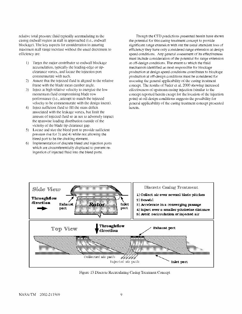
existing re-circulating casing treatments could be realized byimplementing a discrete self-recirculating casing treatmentconcept. Figure 13 shows a representation of such a concept.As shown in Figure 13 low momentum fluid is bled through
discrete bleed ports along the compressor casing near the bladetrailing edge (or where an available source of sufficient high-
pressure fluid can be obtained). The low momentum fluid bled
off via the bleed ports is then de-swirled as necessary andaccelerated through a convergent channel where it is re-injected into the blade passage via discrete injection portslocated near the blade leading edge (or where deemed mostbeneficial to overall performance). Due to the increased static
pressure of the bleed fluid relative to the injection fluid in therotor frame of reference the casing treatment increases therelative total pressure of the fluid in the casing treatment flowpath. The injection ports are circumferentially displaced
relative to the bleed ports to preclude the potential for re-ingestion of the injected fluid into the bleed ports. Thisalleviates the tendency for typical self-recirculating casing
treatments to produce excessively high temperatures along thecase and in the casing treatment flow path due to re-workingcontinually re-circulated fluid which can result in melting ofthe casing treatment components (Kerney, P., 1994).
CONCLUSIONS
A self-recirculating casing treatment concept has been
demonstrated via CFD simulations to provide a considerablebenefit in stall range extension with no predicted loss inefficiency or total pressure rise capability. The concept is
shown to benefit performance by decreasing the extent of low
NASA/T_2002-211569 8
relative total pressure fluid typically accumulating in the
casing endwall region as stall is approached (i.e., endwall
blockage). The key aspects for consideration in assuring
maximum stall range increase without the usual decrement to
efficiency are:
1) Target the major contributor to endwall blockage
accumulation, typically the leading-edge or tip-
clearance vortex, and locate the injection port
commensurate with such.
2) Assure that the injected fluid is aligned in the relative
frame with the blade mean camber angle.
3) Inject at high relative velocity to energize the low
momentum fluid compromising blade row
performance (i.e., attempt to match the injected
velocity to be commensurate with the design intent).
4) Inject sufficient fluid to fill the mass deficit
associated with the leakage vortex, but limit the
amount of injected fluid so as not to adversely impact
the spanwise loading distribution outside of the
vicinity of the blade tip clearance gap.
5) Locate and size the bleed port to provide sufficient
pressure rise for 3) and 4) while not allowing the
bleed port to be the choking element.
6) Implementation of discrete bleed and injection ports
which are circumferentially displaced to prevent re-
ingestion of injected fluid into the bleed ports.
Though the CFD predictions presented herein have shown
the potential for this casing treatment concept to provide
significant range extension with out the usual attendant loss of
efficiency they have only considered range extension at design
speed conditions. Any general assessment of its effectiveness
must include consideration of the potential for range extension
at oft-design conditions. The extent to which the fluid
mechanism identified as most responsible for blockage
production at design speed conditions contributes to blockage
production at oft-design conditions must be considered for
assessing the general applicability of the casing treatment
concept. The results of Suder et al, 2000 showing increased
effectiveness of upstream casing injection (similar to the
concept reported herein except for the location of the injection
point) at oft-design conditions suggests the possibility for
general applicability of the casing treatment concept presented
herein.
S deThro_hflow /
direction Es...............,:: ::#@iiiq':i}iiii@ii@iiiiii':i
: pore
1) Collect air over several blade pitches
2 ) Deswirl
3) Accelerate in a converging ims_age
4) Inject over a smaller pltchwlse dlstm_ce
5) _vold reclrc_Istlon oflnjected air
.] Throaghflow
_@_ V_@W _ directlo- S E_Imust port
Figure 13 Discrete Recirculating Casing Treatment Concept
NASA/T_2002-211569 9

REFERENCES
Adamczyk, J. J., "Model Equation for Simulating Flows in
Multistage Turbomachinery," ASME Paper No. 85-GT-226,1985.
Cho, D. L., "Effect of Vortex Core Stagnation Pressure on TipClearance Flow Blockage in Turbomachines, "Masters Thesis,Massachusetts Institute of Technology, September, 1995.
Crook, A. J., Greitzer, E. M., Tan, C. S., Adamczyk, J. J.,"Numerical Simulation of Compressor Endwall and CasingTreatment Flow Phenomena," ASME Journal of
Turbomachinery, Vol. 115, pp. 501-512, July 1993.
Cumpsty. N. A., "Part-Circumference Casing Treatment andthe Effect on Compressor Stall, " ASME paper No. 89-GT-312, 1989.
Hathaway, M. D., Strazisar, A. J., "Impact of Discrete TipInjection on Stabilization of a Transonic Compressor Rotor,"21 st Army Science Conference, Norfolk, VA, June 15-17,1998.
Hobbs, D. E., "Active Vaned Passage Casing Treatment, "
U.S. Patent (5,431.533), July 11, 1995.
Janssens, G., Chedozeau, M., "Controle du Decollement
Parietal dans les Compresseurs Axiaux par Aspiration ouSoufflage de la Couche Limite, " Communication presentee auXVI Colloque d'Aerodynamique Appliquee (AAAF), Lille,13-15 November, 1979.
Kerney, R "Recirculating Cavity Casing Treatment Failure, "
Wright Laboratories Report WL-TR-94-2092, 1994.
Khalid, S., "The Effects of Tip Clearance on AxialCompressor Pressure Rise, " Ph.D. Dissertation,
Massachusetts Institute of Technology, 1994.
Khalid, S. A., Khalsa, A. S., Waltz, I. A., Greitzer, E. M., Tan,
C. S., Cumptsy, N. A. Adamczyk, J. J., Marble, F. E., "EndwallBlockage in Axial Compressors, " ASME Paper 98-GT-188,1998.
Koch, C. C., Smith, L. H. Jr., "Experimental Evaluation ofOuter Casing Blowing or Bleeding of Single Stage Axial Flow
Compressor, Part IV - Performance of Blowing InsertConfiguration No. 1," NASA CR-54589, 1968a.
Koch, C. C., Smith, L. H. Jr., "Experimental Evaluation ofOuter Casing Blowing or Bleeding of Single Stage Axial FlowCompressor, Part IV - Performance of Bleed Insert
Configuration No. 3," NASA CR-54590, 1968b.
Koch, C. C., "Stalling Pressure Rise Capability of Axial Flow
Compressor Stages, " Transaction of the ASME, Journal ofEngineering for Power, Vol. 103, pp. 645-656, October, 1981.
Koff, S. G., Mazzawy, R. S., Nikkanen, J. P., Nolcheff, N. A.,
"Case Treatment for Compressor Blades. " U.S. Patent(5,282,718), February 1, 1994.
Nolcheff, N. A., "Flow Aligned Plenum Endwall Treatment forCompressor Blades, " U.S. Patent (5,586,859), December 24,1996.
Prince, D. C. Jr., Wisler, D. D., Hivers, D. E., "Study ofCasing Treatment Stall Margin Improvement," NASA CR-134552, 1974.
Shabbir. A., Celetina, M. L., Adamczyk, J. J., and Strazisar, A.J., "The Effect of Hub Leakage Flow on Two High SpeedAxial Flow Compressor Rotors," ASME Paper No. 97-GT-346, 1997
Shih, T. H., Liou, W. W., Shabbir, A., Zhu, J. and Yang, Z., "ANew k-e Eddy Viscosity Model for High Reynolds NumberTurbulent Flows, "Computers Fluids, 24, 3,227-328, 1995.
Shih, T. H., Zhu, J. Celestina, M. L., "Assessment of Three
Turbulence Models in a Compressor Rotor, " ASME PaperNo. 96-GT-198, 1996.
Smith, G. D. J., Cumpsty, N. A., "Flow Phenomena inCompressor Casing Treatment, " ASME Journal of
Engineering for Gas Turbine and Power, Vol. 106, pp. 532-541, January 1, 1982.
Smith, L. H., "Casing Boundary Layers in Multistage Axial-Flow Compressors, " Flow Research on Blading, ed., L. S.Dzung, Elsevier, Amsterdam, 1970.
Suder, K. L., Hathaway, M. D., Thorp, S. A., Strazisar, A. J.,Bright, M. B., "Compressor Stability Enhancement UsingDiscrete Tip Injection." ASME Paper 2000-GT-0571,
accepted for publication in the Transactions of the ASME,2000.
Suder, K. L., Experimental Investigation of the Flow Field in aTransonic, Axial Flow Compressor With Respect to theDevelopment of Blockage and Loss, " NASA TM 107310,October, 1996.
Strazisar, A. J., Wood, J. R., Hathaway, M. D., Suder, K. L.,"Laser Anemometer Measurements in a Transonic Axial-Flow
Fan Rotor, "NASA TP 2879, November, 1989.
Takata, H., and Tsukuda, Y. "Stall Margin Improvement byCasing Treatment - It's Mechanism and Effectiveness," ASMEJournal of Engineering for Power, Vol. 99, pp. 121-133, 1977.
Van Zante, D. Z., Strazisar, A. J., Wood, J. R., Hathaway, M.D., Okiishi, T. H., "Recommendations for Achieving Accurate
Numerical Simulation of Tip Clearance Flows in TransonicCompressor Rotors, " ASME Paper 99-GT-390, accepted forpublication in the Transaction of the ASME, 1999.
NASA/T_2002-211569 10

Form ApprovedREPORT DOCUMENTATION PAGEOMB No. 0704-0188
Public reporting burden for this collection of information is estimated to average 1 hour per response, including the time for reviewing instructions, searching existing data sources,gathering and maintainingthe data needed, and completing and reviewingthe collection of information. Send comments regarding this burden estimate or any other aspect of thiscollection of information, including suggestions for reducing this burden, to Washington Headquarters Services, Directorate for Information Operations and Reports, 1215 JeffersonDavis Highway, Suite 1204, Arlington, VA 22202-4302, and to the Office of Management and Budget, Paperwork Reduction Project (0704-0188),Washington, DC 20503.
1. AGENCY USE ONLY (Leave blank) 2. REPORT DATE 3. REPORT TYPE AND DATES COVERED
July 2002 Technical Memorandum
5. FUNDING NUMBERS4. TITLE AND SUBTITLE
Self-Recirculating Casing Treatment Concept for Enhanced Compressor
Performance
6. AUTHOR(S)
Michael D. Hathaway
7. PERFORMING ORGANIZATION NAME(S) AND ADDRESS(ES)
National Aeronautics and Space Administration
John H. Glenn Research Center at Lewis Field
Cleveland, Ohio 44135-3191
9. SPONSORING/MONITORING AGENCY NAME(S) AND ADDRESS(ES)
National Aeronautics and Space Administration
Washington, DC 20546 0001and
U.S. Army Research Laboratory
Adelphi, Maryland 20783 1145
WU-714-03-20-00
1L161102AH45
8. PERFORMING ORGANIZATIONREPORT NUMBER
E-13353
10. SPONSORING/MONITORINGAGENCY REPORT NUMBER
NASA TM--2002-211569
ARL-TR-2748
GT-2002-30368
11. SUPPLEMENTARY NOTES
Prepared for the Turbo Expo 2002 cosponsored by the American Society of Mechanical Engineers and the International
Gas Turbine Institute, Amsterdam, The Netherlands, June 3-6, 2002. Responsible person, Michael D. Hathaway,
organization code 5810, 216-433-6250.
12a. DISTRIBUTION/AVAILABILITY STATEMENT
Unclassified - Unlimited
Subject Category: 07 Distribution: Nonstandard
Available electronically at t_ltp:/Igltrs.grc.na_sa.gov/GEI'RS
This publication is available from the NASA Center for AeroSpace Information, 301-621-0390.
12b. DISTRIBUTION CODE
13. ABSTRACT (Maximum 200 words)
A state-of-the-art CFD code (APNASA) was employed in a computationally based investigation of the impact of casing
bleed and injection on the stability and performance of a moderate speed fan rotor wherein the stalling mass flow is
controlled by tip flow field breakdown. The investigation was guided by observed trends in endwall flow characteristics
(e.g., increasing endwall aerodynamic blockage) as stall is approached and based on the hypothesis that application of
bleed or injection can mitigate these trends. The "best" bleed and injection configurations were then combined to yield a
self-recirculating casing treatment concept. The results of this investigation yielded: 1) identification of the fluid mecha-
nisms which precipitate stall of tip critical blade rows, and 2) an approach to recirculated casing treatment which results in
increased compressor stall range with minimal or no loss in efficiency. Subsequent application of this approach to a high
speed transonic rotor successfully yielded significant improvements in stall range with no loss in compressor efficiency.
14. SUBJECT TERMS
Machines for compressing air or other fluids
17. SECURITY CLASSIFICATIONOF REPORT
Unclassified
NSN 7540-01-280-5500
15. NUMBER OF PAGES
1616. PRICE CODE
18. SECURITY CLASSIFICATION 19. SECURITY CLASSIFICATION 20. LIMITATION OF ABSTRACTOF THIS PAGE OF ABSTRACT
Unclassified Unclassified
Standard Form 298 (Rev. 2-89)
Prescribed by ANSI Std. Z39-18298-102