Embed Size (px)
Citation preview

SOFTWARE MAINTENANCE: RESEARCH AND PRACTICEJ. Softw. Maint: Res. Pract.10, 279–303 (1998)
Research
Documentu: A Flexible Architecture forDocumentation Production Based on aReverse-engineering Strategy
CHRISTIANO de OLIVEIRA BRAGA*, ARNDT von STAA and JULIO CESAR SAMPAIO do PRADOLEITE
Departamento de Informa´tica da Pontifı´cia Universidade Cato´lica do Rio de Janeiro, R. Marqueˆs de S.Vicente 225, Rio de Janeiro, RJ 22453–900, Brazil
SUMMARY
Good documentation is essential to the production and evolution of quality software. Based ona survey on program documentation, we propose a documentation architecture that aims tofulfil several requirements of an ideal solution. The architecture integrates a powerful transform-ation system (Draco-PUC) and a versatile CASE tool (Talisman) in order to produce documentsusing reverse-engineering strategies. We have implemented such an approach in a prototypetool called Documentu, which uses a database to store system-wide information and uses astandard HTML hypertext browser to help the access and navigation of system documentation.The prototype was used on a large scientific system that belongs to an oil company, withpositive results. 1998 John Wiley & Sons, Ltd.
KEY WORDS: documentation; transformation systems; CASE tools: software engineering; tool integration;reverse engineering
1. INTRODUCTIONOne of the goals of a software process is to provide the necessary information to
maintain evolving software systems. Usually, most of the system information is solelyembedded in the current source code. However, other sources of information should beavailable in order to provide a better understanding of the software and its environment(Biggerstaff, Mitbarden and Webster, 1994; Selfridge, Waters and Chikofsky, 1993; Leiteand Cerqueira, 1995). Good documentation, easily accessible and easy to read has beensought for a long time (Horowitz, Kemper and Narasimham, 1985; Garg and Scacchi,1990). It is essential to software production, which employs several software engineers,working in a co-operative fashion.
CENPES is the research institute of Petrobra´s, the Brazilian Government Oil Company.
* Correspondence to: Christiano de Oliveira Braga, Departamento de Informa´tica da Pontifı´cia, UniversidadeCatolica do Rio de Janeiro, R. Marqueˆs de S. Vicente 225, Rio de Janeiro, RJ 22453–900, Brazil. Email:cbragaKinf.puc-rio.br
CCC 1040-550X/98/040279–25$17.50 Received 17 December 1997 1998 John Wiley & Sons, Ltd. Revised 11 May 1998

280 CHRISTIANO DE OLIVEIRA BRAGA ET AL.
This centre uses several software systems developed both internally and by third parties.One of its projects, DOC, was created in order to improve the quality of the softwareproducts developed at CENPES, by making the maintenance process easier and increasingthe quality of the documentation assets. The project is a partnership between LES—Software Engineering Laboratory at PUC-Rio and CENPES.
One of the deliverables of the DOC project was a set of guidelines for developmentand documentation of software code (Staaet al., 1995, p. 5). However, practical experiencehas shown us that the guidelines would only produce the expected feedback if they couldbe assisted by a software tool.
We have surveyed some of the existing proposals for documentation tools at the codelevel, and based on their strong and weak points, we propose our architecture for a toolthat implements automatic support to the guidelines. Our proposal uses HTML (hypertextmark-up language) and relates the information in terms of the whole system, not only forindividual programs. The tool generates documentation for annotated and unmarked codeas well.
We have implemented our proposal in a tool calledDocumentu(Braga, Staa and Leite,1997, pp. 9–13). The main objectives of the tool are:
• help software personnel in the maintenance task;• aid the software users in realizing the features and facilities of the product if the
software being developed is in a library; and• help a new developer to understand the software system with which he is going
to work.
Documentuideally uses code tag-marked as defined by Staa’s guidelines, like namingvariables or functions and inserting annotations in comments to document design decisions.The guidelines also provide for object-oriented programming and testing. The guidelinesdeal with higher abstraction levels as well, making suggestions on how to structuresoftware projects. However,Documentucan also produce documentation from bare sourcecode. This is possible because we generate software documentation based on both thesource-code grammar and the mark-up grammar. We have used the transformation systemof Draco-PUC (Leite, Sant’Anna and Freitas, 1994) to recover system information fromcode and mark-ups. The Talisman CASE tool (Staa, 1993, p. 1.1) was used to store,validate and format the information. Finally we use a standard HTML browser to accessthe resulting documentation.
The transformation system plays the role of the extractor, analysing and retrieving codeinformation. This information is extracted using syntax analysis and, if needs be, mark-ups. This information is passed to the CASE tool that stores it in a repository. Thisrepository has database management capabilities and is able to provide a series ofconsistency checks that can be applied to the entire system. Using the information in therepository, the CASE tool generates an HTML file by means of special procedurescalled linearizers.
Before detailing our proposal we make a brief survey of existing documentationproposals (Section 2). In Section 3, we describe the tool architecture. In Section 4, theDocumentutool is presented. Section 5 reports on the results of applyingDocumentuto
1998 John Wiley & Sons, Ltd. J. Softw. Maint: Res. Pract.10, 279–303 (1998)

281DOCUMENTU
working scientific software. Section 6 presents what can be generated with the currentversion of the tool. We conclude the paper in Section 7, referring to related work andreporting on our plans for the evolution ofDocumentuand its use.
2. A BRIEF SURVEY ON DOCUMENTATION PREPARATION
2.1. Document standardsThere is no doubt of the importance of presenting software artefacts as structured and
readable documents. Nowadays, this issue is confronted with a plethora of new possibilitiesthrough the widespread diffusion of the World Wide Web and itslingua franca, HTML.
Our work was based on this perception and on key literature, which we classified underthe following categories: standards, literate programming, using mark-up languages anddatabases, and recent documentation tools.
SGML (Goldfarb, 1990, pp. 217–494) is the ISO-8879 ISO standard for structureddocuments. The standard describes a language for document description. This languagedefines tags to be embedded in the text, in order to structure the document. The tagshave the form,cmd. to begin a structure and,\cmd. to end it. A simple examplewould be:
,Paragraph .
This an example of a paragraph tag in SGML
, \Paragraph .
A style sheet can be applied over the document to produce a pretty-printed view ofthe document, following a document DTD (Document Type Definition). A DTD definesa structure for a class of documents. Figure 1 shows an example of DTDs.
A document created following the SGML DTD defined in Figure 1 would be composedof MANINFO (managerial information), USEINFO (use information) andIMPLEMENTINFO (implementation information). In the example of Figure 1 we havedetailed the managerial information that could be composed ofProject, FileType ,IdNumber, Version, DataAp , and Author . Among those,IdNumber is optionalandAuthor may include it one or more times. All documents created using this structurewould necessarily have those sections.
Figure 1. Example of an SGML DTD
1998 John Wiley & Sons, Ltd. J. Softw. Maint: Res. Pract.10, 279–303 (1998)

282 CHRISTIANO DE OLIVEIRA BRAGA ET AL.
HTML (World Wide Web Consortium, 1995) is based upon a subset and applicationof the SGML standard. The language is used to create portable hypertext documents. TheHTML mark-ups can represent hypertext news, electronic mail, documentation, hypermedia,options menu, databases query results and structured documents with graphics. HTML hasbeen used in the World Wide Web since 1990. The most important difference betweenHTML and SGML is that the former has the capacity to refer to other documents throughlinks defined with mark-ups. Another relevant difference between SGML and HTML isthat the programmer cannot develop different DTDs in HTML. All HTML documentshave to follow a fixed structure, defined by the HTML standard.
The Office Document Architecture (ODA) (Appelt and Tetteh-Lartey, 1993; Brown,1989) is an object-oriented framework, created to be a standard for document exchange.ODA, like SGML, distinguishes between the logical structure and the layout structure ofthe document (see Figure 2).
While SGML and ODA have different approaches to solve the same problem—documentation exchange—both of them emphasize a very important issue in docu-mentation: the essential difference between the document structure and the layout structure.Also, both of them fail in supporting the creation of hypertext documents.
Figure 2. Diagram of the ODA architecture
1998 John Wiley & Sons, Ltd. J. Softw. Maint: Res. Pract.10, 279–303 (1998)
283DOCUMENTU
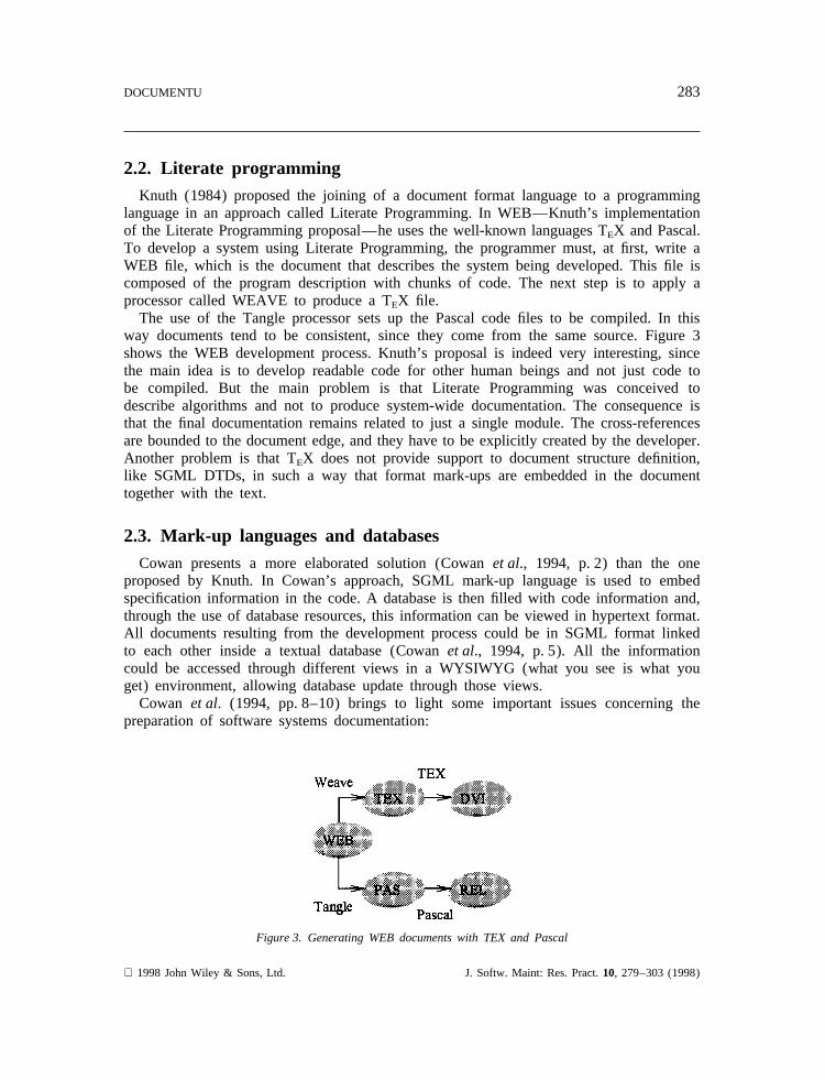
2.2. Literate programmingKnuth (1984) proposed the joining of a document format language to a programming
language in an approach called Literate Programming. In WEB—Knuth’s implementationof the Literate Programming proposal—he uses the well-known languages TEX and Pascal.To develop a system using Literate Programming, the programmer must, at first, write aWEB file, which is the document that describes the system being developed. This file iscomposed of the program description with chunks of code. The next step is to apply aprocessor called WEAVE to produce a TEX file.
The use of the Tangle processor sets up the Pascal code files to be compiled. In thisway documents tend to be consistent, since they come from the same source. Figure 3shows the WEB development process. Knuth’s proposal is indeed very interesting, sincethe main idea is to develop readable code for other human beings and not just code tobe compiled. But the main problem is that Literate Programming was conceived todescribe algorithms and not to produce system-wide documentation. The consequence isthat the final documentation remains related to just a single module. The cross-referencesare bounded to the document edge, and they have to be explicitly created by the developer.Another problem is that TEX does not provide support to document structure definition,like SGML DTDs, in such a way that format mark-ups are embedded in the documenttogether with the text.
2.3. Mark-up languages and databasesCowan presents a more elaborated solution (Cowanet al., 1994, p. 2) than the one
proposed by Knuth. In Cowan’s approach, SGML mark-up language is used to embedspecification information in the code. A database is then filled with code information and,through the use of database resources, this information can be viewed in hypertext format.All documents resulting from the development process could be in SGML format linkedto each other inside a textual database (Cowanet al., 1994, p. 5). All the informationcould be accessed through different views in a WYSIWYG (what you see is what youget) environment, allowing database update through those views.
Cowan et al. (1994, pp. 8–10) brings to light some important issues concerning thepreparation of software systems documentation:
Figure 3. Generating WEB documents with TEX and Pascal
1998 John Wiley & Sons, Ltd. J. Softw. Maint: Res. Pract.10, 279–303 (1998)

284 CHRISTIANO DE OLIVEIRA BRAGA ET AL.
• the need for a document logical structure, defined by a standard in order to achievedocument portability;
• the need for databases, to store the system-wide code information, allowing validationsover the gathered data;
• the use of a hypertext browser to navigate across the information.
2.4. Documentation toolsThere are several tools available to support the generation of software development
process documentation, but most of them only produce documentation automaticallywithout checking for consistency with the code.
Java (Gosling, Joy and Steele, 1996, p. 1) is a programming language developed atSun Microsystems to support the development of portable and reusable software compo-nents. Figure 4 shows the browsing of a document generated by JavaDoc (Flanagan,1996, pp. 220–221), a tool that generates HTML documents from tag-annotated Javasource code. The document in Figure 4 was generated from the annotated code presentedin Figure 5.
JavaDoc formats public and protected information from classes, interfaces, constructors,methods and fields. Figure 5 shows an example of JavaDoc tags. HTML tags can alsobe used to format comments. User-defined cross-reference tags, such asKsee (not shown
Figure 4. Example of JavaDoc document browsing
1998 John Wiley & Sons, Ltd. J. Softw. Maint: Res. Pract.10, 279–303 (1998)

285DOCUMENTU
Figure 5. Example of annotated Java code
in the example), may be manually inserted. JavaDoc creates documentation (an index, aclass hierarchy and description files) for Java source files or for packages.
Microsoft provides an unsupported tool called AutoDuck. This tool works much likeJavaDoc. It uses mark-up tags in the source code to generate documentation. Thisdocumentation is generated in RTF (Rich Text Format—a Microsoft standard availablefor Windows, OS/2 and MacOS platforms). RTF is the format used by the MicrosoftHelp Compiler to generate Windows Help files. The AutoDuck tagKclass (see examplein Figure 6) defines the name of a class andKcmember defines a class member. Sincethe class in the example is a template,Ktargs defines the class templates arguments.Figure 7 shows the browsing, using the Windows help system, for the example presented.
AutoDuck provides the capability of parsing user-defined tags. JavaDoc parses only itspredefined tags. Both of them are easily integrated into the building process throughmakefile invocation, improving documentation consistency with the source code. If themark-ups were consistently updated and the documentation generated whenever the codechanged, then the documentation would always be consistent with its associated sourcecode.
AutoDuck does not support system-wide documentation. It is only concerned aboutlocal modules and cross-references have to be created manually by the developer, generat-ing possible sources of inconsistency. Neither AutoDuck nor JavaDoc perform consistencychecking in the retrieved information.
1998 John Wiley & Sons, Ltd. J. Softw. Maint: Res. Pract.10, 279–303 (1998)

286 CHRISTIANO DE OLIVEIRA BRAGA ET AL.
Figure 6. Example of AutoDuck tags
2.5. Some important issues about documentation preparationThe main concept to keep in mind is that software programs have to be written for
human beings, and not only to be processed by computers (Knuth, 1984). The existenceof a document logical structure, defined using a standard in order to achieve documentportability is a major issue (Goldfarb, 1990, pp. 402–433). To store system-wide codeinformation and thus allow checking among information fragments, requires the use of adatabase (Cowanet al., 1994, p. 8). Another important issue is the use of a hypertextbrowser to navigate through the information (Bigelow, 1988; Rajlichet al., 1990). Theuse of hypertext provides an easy way to access on-line information, as well as allowinginformation layering, such that information can be structured.
3. THE PROPOSED ARCHITECTURE
3.1. Draco-PUCOur proposal is geared to marked code, but it also treats unmarked code. This makes
possible the generation of the documentation based solely on a system’s source code(currently C, C++ and FORTRAN 77). It is important to emphasize that the tags onlycomplement the information already captured by the tool.Documentu is a tool thatinstantiates our proposal. The marks treated by our proposal are based on coding guidelines.Section 4 describes these coding standards. If there is no documentation available in the
1998 John Wiley & Sons, Ltd. J. Softw. Maint: Res. Pract.10, 279–303 (1998)

287DOCUMENTU
Figure 7. Example of AutoDuck browsing
code, the information shown in the generated documentation is what can be inferred fromthe source-code language syntax through parsing and transformation.
The information extractor (see Figure 8) parses the source code and produces informationthat is used by the information formatter system. The formatter system then produces ahypertext system in HTML. The first part of the process, the information extractor system,uses the Draco-PUC (Leite, Sant’Anna and Freitas, 1994) transformation capabilities. The
Figure 8. Outline of the proposed architecture
1998 John Wiley & Sons, Ltd. J. Softw. Maint: Res. Pract.10, 279–303 (1998)

288 CHRISTIANO DE OLIVEIRA BRAGA ET AL.
second part of the architecture, the information formatter system, is based on a repository-based CASE tool called Talisman (Staa, 1993, p. 1.7).
Draco-PUC (Leite, Sant’anna and Freitas, 1994) is a transformation system thatimplements the Draco paradigm (Neighbors, 1984). This paradigm performs softwaredevelopment by creating and reusing domains, at a high level of abstraction. An essentialpart of a domain description in Draco-PUC is a grammar definition written in a BNF-like style. Using this grammar as input, thepargen subsystem (parsergenerator), producesthe domain parser. The unparser or pretty-printer is also created when the grammar isannotated with layout directives.
A special abstract syntax tree (DAST—Draco Abstract Syntax Tree) is created to storethe information retrieved by the parser. Once this structure is created, it is possible toapply the unparser to view the information in the DAST as described in the layoutdirectives. It is also possible to apply transformations to map the information in the DASTto a new structure over the same domain (intra-domain transformations) or to a newdomain using inter-domain transformations.
A Draco-PUC transformation has a left-hand side (LHS), which defines a searchingpattern and a right-hand side (RHS), which defines a replacement pattern. Control pointsand transformation properties are also available. These kinds of features are responsiblefor driving the transformation engine in a bottom–up search-and-replace way. The controlpoints of a transformation are:
• Pre-match—executed when the engine tries to execute the transformation.• Match constraint—executed every time a pattern variable is bound against a program
fragment when the transformation matching is being attempted.• Match failure —executed when the transformation matching fails.• Post-match—executed right after the successful matching of the transformation.• Pre-apply—executed before the replacement of the LHS by the RHS.• Post-apply—executed after a pattern is substituted.
Transformation rules are grouped in transformation sets, which also have controlpoints (initialization and end) and properties. Sets of transformations are encapsulated ontransformers. Transformers have three control points: declaration (global objectdeclaration), initialization and end.
Draco-PUC transformations can be in-place transformations, when the substitution patternis replaced in the source, or they can work with workspaces. Transformations that useworkspaces are non-destructive and the replacement patterns are not instantiated in analysedsource, but rather in an external workspace. When using workspaces, it is also necessaryto define templates, which are Draco-PUC transformation language structures that allowthe developer to instantiate the RHS in target workspaces.
The use of workspaces can be viewed as an asynchronous replacement, where the RHSis written in a temporary space for further use. As an example of such use, consider thecreation of a relation between one element that was already found by the analyser andanother that is to be found. A workspace should be used to create this late association.An example will be presented in Section 4.1.
1998 John Wiley & Sons, Ltd. J. Softw. Maint: Res. Pract.10, 279–303 (1998)

289DOCUMENTU
3.2. Talisman CASE tool
Talisman (Staa, 1993, p. 1.7) is a repository-based CASE tool. It provides an environ-ment including predefined database schemas, calledTalisman Definition Languages(Staa,1993, p. 1.11) that give the semantics to the existing information inside a software base.Talisman supports languages for structured analysis, and diagrams like the data-flowdiagram for data modelling, and the entity-relationship diagram for information systemsmodelling. Talisman also allows the definition of such languages, thus making customiz-ation an easy task.
A software base (Staa, 1993, p. 1.7) is a database composed of textual fragments andreferences to textual fragments inside the database. A definition language (Staa, 1993,p. 14.1) is characterized by the relations among its elements (modules, classes andfunctions, for example) and alsoform programs(validators and linearizers). Thoseformprogramscould be loaded at run time to customize the environment. The validators checkfor consistency of the data inside the software base, whereas the linearizers producereports with the information contained inside the software base. When a software systemis developed, editor forms are used to populate the software base with specification textfragments. Each text fragment can have different roles depending on which definitionlanguage is being used. For instance, a data repository in a data-flow diagram can berepresented as a table in an entity-relationship diagram.
Once the software base is populated, the validators have to be applied to performconsistency checking with the information inside the base. With the information validated,the linearizers are applied to produce documentation or code.
3.3. Integration of the tools
The information extractor system (Figure 8) is set up on Draco-PUC by means of twodomains: the C/C++ domain and the Talisman domain. The C/C++ domain was alreadyavailable as a Draco-PUC executable domain. This domain has been used by severalpeople in different projects, indicating its robustness. However, it was necessary to extendthe domain in order to make possible the analysis of special tags.
Talisman has an importing feature that allows the CASE environment to populate anexisting base with information provided by imported files. The rules that guide the creationof this file can be written as a grammar. Using this grammar, the Talisman domain wascreated at the Draco-PUC machine.
The process starts with the analysis of the source code. Once the code of a givenmodule is analysed and the Draco-PUC abstract syntax tree is created, a set of transform-ations, created specially to implement this approach, are applied over that internal formatin order to create the Talisman import file for that module. This operation is repeated foreach module described in a Draco-PUC script file (DSF file). A Draco script file iswritten for the whole system, capturing all the modules it comprises.
Figure 9 shows this process. In the first phase, tagged (or not tagged) code is analysedby the transformation system, generating the import files to the Talisman CASE tool. Thesecond part of the process is restricted to Talisman. Each import file outputted by theDraco-PUC machine is then imported to the Talisman environment. Once all the files are
1998 John Wiley & Sons, Ltd. J. Softw. Maint: Res. Pract.10, 279–303 (1998)

290 CHRISTIANO DE OLIVEIRA BRAGA ET AL.
Figure 9. Diagram of theDocumentuexecution process
imported, the validators are executed, checking the data consistency inside the base. Theylook for text fragment completion and cross-reference validation. A log is created withthe inconsistencies that have been found. When the base is validated, the linearizers areexecuted to create the HTML documents.
4. DOCUMENTU
4.1. Role of Draco-PUC in the architectureWe describeDocumentuby focusing on details of its architecture, its execution and
the results produced. The tool is based on three Draco-PUC domains, C++, FORTRANand the Talisman domain, and on the repository defined in Talisman. Below we givedetails on how these parts are organized.
As cited before, the basis for a Draco-PUC domain description is its language grammardescription. A domain-language grammar description is written in an extended-BNF style.An example of such grammar descriptions is shown in Figure 10, which presents theCPP grammar format for a C++ language fragment responsible for the description of classheads like:
class Cwindow {. . .}/ /Or . . .class CMyWindow : CWindow {. . .}/ /Or . . .class CAnotherWindow : CWindow, CBaseWindow {. . .}
Just like with C++, the Talisman import file grammar description was also encapsulated
1998 John Wiley & Sons, Ltd. J. Softw. Maint: Res. Pract.10, 279–303 (1998)

291DOCUMENTU
Figure 10. Fragments of the CPP and Talis grammars
in Draco-PUC. An excerpt of this grammar (Talis), which describes textual import entryfor the repository is also shown in Figure 10. An example of a textual import entryis the one Documentuuses when defining descriptive long names for classes in theTalisman repository.
After the grammars were defined, transformations were created to retrieve the informationfrom the C/C++ code into the Talisman domain in such a way that it could be used inthe CASE tool. The retrieved information comes from the language (C/C++) analysis,and also from the embedded tags following the specification information, defined in Staaet al. 1995, pp. 11–32) as part of a set of C/C++ coding standards. The embedded tags
1998 John Wiley & Sons, Ltd. J. Softw. Maint: Res. Pract.10, 279–303 (1998)

292 CHRISTIANO DE OLIVEIRA BRAGA ET AL.
Figure 11. Examples of embedded tags
appear as comments, so they do not change the compilation process. Figure 11 presentsan example of such tags embedded in C++ code.
In Documentu, there are two types of transformations: tag matching and structurematching (concerning language structures). The tag-matching transformations retrieve thedesign information embedded in the code as comments (Staaet al., 1995, pp. 11–32).The structure-matching transformations are intended to retrieve information about theprogram structure using the code itself as the main source of information. The docu-mentation structure is created using the information retrieved by these transformations.
An example of a tag-matching transformation is shown in Figure 12. The transformationlooks for a class name tag specification($CNAME) and then stores the proper informationin a workspace(WSClassLongName) . Following Staa’s commenting standard, eachclass should have a long name in order to provide a better understanding of the abstraction.Later in the transformation process, a transformation that looks for classes, as in Figure13, will be executed and will use the name stored in that workspace to set the long nameattribute for the associated class. The class that will have the attribute set is the nextclass following the comment describing theCNAMEattribute.
Figure 12. Example of a tag-matching transformation
1998 John Wiley & Sons, Ltd. J. Softw. Maint: Res. Pract.10, 279–303 (1998)

293DOCUMENTU
Figure 13. Example of a structure-matching transformation
The Class transform is an example of a structure-matching transformation. This trans-formation is responsible for generating the text that will create a class element in theTalisman repository (this is like creating a record in a relation database). This transform-ation also gathers other information from several workspaces concerning the class beinganalysed, and generates the text for what is gathered. This text will be imported byTalisman to populate the repository. An example of the generated text would be:
DA “Class” “VM FSegment” Name
DA “Class” “VM FSegment” Text ClassName
VMS – Segment
#K#
The first line creates a Talisman class element named VMFSegment. The second linesets theClassLongname attribute of VMFSegment to VMS–Segment.
In the current version of the tool, the set of transformations cannot be expanded by aregular user. Once the transformation is written and compiled, it is only necessary to addit to the Draco–PUC script that applies the transformations. The problem is to write thetransformations. The user needs to understand the C++ grammar—written in a BNF-likesyntax—to learn Draco-PUC transformation language and know the structure of thealready implemented transformations in order to use the retrieved context information.Also, the compiler used to generate Draco-PUC has to be the same for all transformations.
4.2. Role of Talisman in the proposed architectureA new definition language has been implemented in Talisman to support theDocumentu
project. It is called Program Documentation language. Figure 14 shows a diagram of thelanguage schema. This new language is based on Modular Programming (Staa, 1993,
1998 John Wiley & Sons, Ltd. J. Softw. Maint: Res. Pract.10, 279–303 (1998)

294 CHRISTIANO DE OLIVEIRA BRAGA ET AL.
Figure 14. Model for Program Documentation definition language in Talisman
p. 22.1), but the information it manages is related to source-code documentation. When afile is imported, the information inside the file populates the software base.
Once the base is filled, the validators should be applied followed by the linearizers. InDocumentua linearizer is responsible for the creation of the hypertext system in HTMLand just like the validator, is aform program. A form program is written using thelanguage available in Talisman, to create programs, that manipulates the software basetext fragments. The validators check the information inside the software base in order toverify its consistency. The linearizer navigates inside the software base looking for specifictext fragments and relations and generates a file with the text fragment information inHTML format. An example of a Talisman form is shown in Figure 15.
Figure 15. Talisman form excerpt
1998 John Wiley & Sons, Ltd. J. Softw. Maint: Res. Pract.10, 279–303 (1998)

295DOCUMENTU
Figure 15 is an excerpt of the class linearizer. The first two lines of the code, afterthe forall statement, just call two other forms (like procedures, in this case). The firstform program creates annotations that will be used by the file splitter at the post-processing phase. The second form program produces the mark-ups that all HTML filesshould have (,HTML.). A line with the class name is created next, using the HTMLmark-up ,H1., since 1 was passed as a parameter to“Create Title” form. Areference to the fileclasses.htm is also created using the form“Create Refer-ence” with “System Classes” as the text reference. Theif clause checks whethera class has a relation with some module or not. If it does, a reference to the relatedmodule will be created writing the module name in the reference.
First the linearizer creates the documentation structure and the index and only then isthe documentation created for each element of an entity. Viewing the documentation asa graph, first the raw nodes with the links are created, then the node attributes are filled.
One may be thinking why Talisman was used, since Draco-PUC could generate allHTML files itself. Talisman was used for the same reasons a database is used in softwaredevelopment. We wanted to be able to generate the documentation using a high-4GL-likelanguage construction. Talismanform languagepossesses these constructions, as shownin Figure 15. The language provides constructions likeforall, exists and alsoprovides the capability to define new procedures. If Talisman were not used, we wouldhave to manipulate text in files generated by Draco-PUC. Also, Talisman is shareware—a pre-requisite since we want to distribute theDocumentutool, well documented and withthe people who built it available to implement the features we wanted, like creating acommand line version of it.
Documentuuses Lua script files to drive all the execution processes. Lua is a portablescript language developed at the Department of Informatics of PUC-Rio (Ierusalimschy,Figueiredo and Celes, 1996). The user only needs to call the main script file with themodule name he or she wants to document. Once the main script file is called, the firstthing it does is to call a pre-processing script file, responsible for calling the C++ pre-processor that expands the source code with the information inside the included headerfiles. The pre-processed code is then analysed and further transformed into another file.
The file built by the transformation process is imported by Talisman, and is used topopulate a software base with the information contained in the file. The HTML generatorscript file then calls Talisman to linearize the software base. The post-processing batchfile calls the file splitter and the character converter to generate the multiple HTML filesand to generate the HTML entities for the accentuated characters respectively. When allthis is done, the user may invoke his or her HTML 3.0 (since the produced documentationis frame based) compliant browser to navigate through the documentation.
4.3. HypertextAll the links are created using the extractor facilities of Draco-PUC (parser and
transformations). The detailed information about each element (class and methods, forexample) comes from the tags text embedded in the code. The information retrieved fromthe code analysis is used to create the hyperdocument structure: the index and hyperlinkscross-referencing system-entities, like modules, functions and classes. This structure is
1998 John Wiley & Sons, Ltd. J. Softw. Maint: Res. Pract.10, 279–303 (1998)

296 CHRISTIANO DE OLIVEIRA BRAGA ET AL.
what is created when no annotations are available in the code comments. The currentimplementation ofDocumentugenerates a hypertext interface organized in two frames asshown in Figure 16.
In Figure 16, the frame in the left side is an index to system elements. The index isorganized in tabs, like Windows selection tabs. The first one is the index to the systemmodules. Each bullet inside that frame represents a link to a module in the system. Whena module is selected in the left frame, the big pane in the right changes, showing thatmodule’s information, like its associated classes, its functions, types and data. The samething can be done with the other three tabs in the left pane, which represent the indexesto classes, functions and types of the system.
Using the links that appear inside the big frame, the user can navigate to the detailedinformation for a given system element. For example, consider the Shell module in Figure16. The user can browse through information such as: classes in a module, functions,types and all the information defined in the model (such as illustrated in Figure 14) and
Figure 16. In this hypertext browsing, the generated text is written in Portuguese. ‘Mo´dulo Shell’ means ‘ShellModule’ and ‘Descric¸ao’ means ‘Description’. There are two links below the big pane title: ‘Mo´dulos dosistema’ meaning ‘System Modules’ and ‘Descric¸ao detalhada do mo´dulo’ meaning ‘Detailed module description’
1998 John Wiley & Sons, Ltd. J. Softw. Maint: Res. Pract.10, 279–303 (1998)

297DOCUMENTU
also, the information in the mark-ups, as defined in Staaet al. (1995, p. 11–32). Figure16 presents a snapshot of the documentation browsing of the module(Shell.h) thathas its classes annotated with mark-ups describing their functionality.
5. USING DOCUMENTU IN A REAL SYSTEMThe development of theDocumentu tool started as part of the DOC project. This
project, between LES (Software Engineering Laboratory at PUC-Rio) and CENPES(Brazilian Petroleum Company Research Centre), has the objective of increasing thequality of the software developed in that center.
In order to validate the tool, a large system being developed at CENPES was chosento be the test case. The chosen system is called Petrox, a simulator for chemical processes.It is composed of an editor where the user may drop objects from a chemical processand simulate the execution of a particular instance of a process. The editor calls functionsimplemented in FORTRAN, which implement the algorithms needed to run the simulation.
Magoo GUI (Graphical User Interface Library) class library is a significant part ofPetrox, currently with 72 header files in 5 057 595 bytes, in almost 208 552 lines ofexpanded code. We have been using Magoo as one of our test cases, since its code usesadvanced features of the C++ language. Classlib—another relevant part of the Petroxproject with 89 files and 369 kbytes—and Vix—a class library for visual object handling,with 43 files and 189 kbytes—were also used to test the tool.
Documentutook 30 minutes transforming the source code on a Pentium 100 runningWindows NT 4.0 to produce the documentation, applying 17 609 transformations. Thedocumentation was spread along 1 803 files using 1 128 953 bytes of disk space. Theseresults sound pretty acceptable, considering the amount of information retrieved and thatthe documentation process is a batch process and may run in off-duty hours. Table 1summarizes the results of runningDocumentuwith Magoo as input.
Talisman linearizers have 32 functions and 2 012 lines of code.Documentuhas 64transformations implemented, distributed as follows:
• 43 concerning C++ classes;• 30 concerning modules;• 40 concerning functions;• 61 concerning methods;• 23 concerning structures, unions and enumerations.
Several features have been implemented in the tool since the delivery of the firstprototype and many difficulties were encountered. The major problem found concerns theC++ parser. One of the first project decisions was that the symbol table generated by thecurrently available C++ parser—that ships with Draco-PUC—should be kept. The reasonwas because we wanted to evolve the project towards a reverse-engineering tool. Thisdecision made a serious impact in the parsing phase, because the pre-processing of thesource code became an obligation, since every type identifier was supposed to be in thesymbol table.
Most of the parsing problems encountered were in system files included in the source
1998 John Wiley & Sons, Ltd. J. Softw. Maint: Res. Pract.10, 279–303 (1998)

298 CHRISTIANO DE OLIVEIRA BRAGA ET AL.
Table 1. Statistics obtained runningDocumentuusing the Magoo class library as input
Module Size in #Tag#Lang.#Tfs Module Size in #Tag#Lang.#Tfsname kilobytes Tfs. Tfs. p/ name kilobytes Tfs. Tfs. p/
module module
ABSTBOX.H 82 057 82 89 171 OBJBIND.H 94 502 75 79 154ABSTSLCT.H 126 587 160 167 327 OBJSTRM.H 65 726 0 1 067 1 067APPLIC.H 65 025 0 0 0 OPTBIND.H 18 322 126 143 269BINDER.H 14 126 57 56 113 OPTBUT.H 83 856 165 168 333BINDMENU.H 103 286 56 65 121 OPTMENU.H 103 870 57 66 123BSELECT.H 87 889 180 181 361 PTRBIND.H 71 040 110 125 235BUTRADIO.H 82 431 93 99 192 RADIO.H 84 653 96 104 200BUTTON.H 78 854 229 226 455 SAFEREF.H 23 185 46 51 97CANVAS.H 78 801 372 354 726 SELECTOR.H 132 599 218 225 443COLLBIND.H 50 192 92 99 191 SEQBIND.H 72 085 122 137 259COMPOSER.H 46 441 461 538 999 SHELL.H 79 648 218 207 425CONTROL.H 71 931 0 708 708 SLCTDLG.H 122 726 66 73 139DATUM.H 12 322 91 94 185 SLCTMENU.H 103 913 57 67 124DFLTBIND.H 130 874 114 117 231 SRCBIND.H 31 041 127 141 268DIALOG.H 93 217 309 299 608 STATUSLN.H 101 138 65 72 137DIMFLOAT.H 63 637 196 194 390 STREAMBL.H 5 249 43 53 96DIMTEXT.H 251 038 221 230 451 STRNG.H 37 297 246 255 501DIMTYPES.H 4 573 0 0 0 STRVLD.H 70 635 94 101 195ENTRBIND.H 16 555 85 94 161 SUBMENU.H 99 907 60 67 127ENUMERAT.H 3 328 73 88 161 SYSDEPEN.H 8 062 0 0 0FILL.H 73 488 47 54 101 TABLE.H 156 298 0 560 28FLAGITEM.H 75 797 69 75 144 TASK.H 3 049 14 14 28FLTVLD.H 51 331 193 187 380 TEXT.H 107 168 161 166 327FRAME.H 81 415 85 89 174 TOGGLE.H 79 375 208 204 412GERAL.H 1 362 8 8 16 TOOLBOX.H 85 174 59 69 128HBOX.H 83 906 59 68 127 UNIT.H 53 308 345 378 723HEAPVIEW.H 101 035 62 70 132 UNITBIND.H 129 936 90 93 183INDEXDLG.H 110 243 60 69 129 UNITID.H 10 520 4 0 4INTVLD.H 50 298 152 146 298 VALIDAT.H 40 816 208 180 388LABEL.H 99 784 184 183 367 VBOX.H 83 966 59 68 127MENU.H 98 398 89 91 180 XGETCH.H 3 473 2 2 4MENUITEM.H 73 950 88 93 181 ZBOX.H 86 102 151 155 306MFLOAT.H 14 446 91 94 185MINTEGER.H 14 216 91 94 185MULTLINE.H 104 036 181 182 363MULTSLCT.H 129 102 109 114 223NUMTYPES.H 121 888 0 23 23
Number of modules 69Size of modules 5 057 595Number of 17 609Appliedtransformation
1998 John Wiley & Sons, Ltd. J. Softw. Maint: Res. Pract.10, 279–303 (1998)

299DOCUMENTU
code by the pre-processor. The majority of our efforts were in making the parser asreliable as possible to support parsing included system files.
It was indeed a very difficult task, which is not fully completed, since the C++ languageis not yet standardized. What should have been done—and will be in the near future—is to remove the symbol table and thus handle every type identifier simply as identifiersand not save context information. Any necessary context information will be handled bythe transformation system. With this strategy, it will not be necessary to handle compiler-specific features of the language, sometimes implemented in system header files.
Another modification that could be done in the parser is to flatten some parts of thegrammar to sequences of identifiers, making the C++ grammar more flexible in relationto its formal description. When using the whole grammar we have to be aware of languageconstructions that will not be handled by the transformation system, but that must bepresent in order to have the code parsed. This is another inheritance from the projectdecision of implementing a parser for a reverse-engineering tool.
Concerning the generated documentation, our experience has shown that using thelanguage grammar to produce the structure of the documentation was pretty successful.Generating documentation from code that did not have any mark-up induced the user toannotate his or her code in order to produce a better documentation.
The system is presently installed in three different host systems at CENPES and it isstill undergoing tests. The actual version is almost stable but still needs some technicalsupport. We expect that it will reach desired stability in the next version provided themodifications discussed above are included.
6. RESULTS ACHIEVEDWe realize that system documentation is a widely studied field with significant proposals
and commercial products providing very powerful and complex solutions. We believe thatour architecture contributes with the following:
• Flexible architecture.Documentuhas an architecture that can be easily maintainedand updated. Without changing the documentation generators, new programminglanguages can be supported by adding a new parser and transformers to the process.Also, the mark-up structure could be changed to follow different documentationguidelines, with different tag structures in the same way a new language is added.By loading new Talisman linearizers the documentation structure can be changed, sothat, for example, instead of an HTML file, a postscript file could be generated.
• Compiler independence. Most of the currently available IDEs (Integrated DevelopmentEnvironments) provide features for code exploration. Our tool supports most of thosefeatures (like attribute, method, class and cross-referencing browsing) and it iscompiler independent.
• System-wide documentation. The documented project can be as wide as the userwants, with references to as many modules and syntactic elements as the existingcode has. Raw documentation, if no documentation tag is used at all, showing thesystem basic structure, can be produced.
• Documentation portability. This comes as a consequence of the use of a standard lang-uage.
1998 John Wiley & Sons, Ltd. J. Softw. Maint: Res. Pract.10, 279–303 (1998)

300 CHRISTIANO DE OLIVEIRA BRAGA ET AL.
It is also important to stress that by using the CASE tool Talisman (Staa, 1993, p. 14.1)it was possible to write form programs that could validate the integrity of the datarelations (validators). After the analysis of the documentation, Talisman linearizers producea hypertext document in HTML. The produced information will be extremely valuable tosoftware personnel, mainly during maintenance. We understand that one of the strongpoints of our proposal is the low coupling among its components.
Also, there are some points we realize that must be reviewed in the next versions ofthe tool:
• Draco-PUC is still a prototype with some problems concerning usability and docu-mentation. Creating the parser is not a very easy task. Talisman has an obsolete userinterface. Creating a command line version, which also fits a lot better with ourbatch documentation process, has solved this. Also, the tool is only available in theWindows platform. We are working on a Unix version.
• The generated documentation is static. The user cannot ‘ask questions’ different fromthose defined in the form programs. We intend to add a feature in the next versionof the tool allowing the user to generate his own ‘questions’, generating HTMLdocuments that satisfy those questions.
7. CONCLUSIONSWe have proposed an architecture to produce high quality system-wide information
based on source code information. Such documentation will be more effective if codestandards are used properly. Our approach uses two different software artifacts to parseand organize the documentation information:
• one is a transformation system, which deals with the information retrieval, and• the other is a CASE tool that deals with the storage and manipulation of the
retrieved information.
Other authors (Wells, Brand and Markosian; 1995; Zoufalyet al., 1995; Newcomb andKotik, 1995) propose the use of transformation systems to help the documentation problem.Our work innovates by using a transformation system together with a repository-basedsystem. For instance, we believe that our proposal, regarding the repository aspect, isrelated to the work of Edwards and Munro (1993), and Jarzabek and Keam (1995).Jarzabek provides a powerful parser to retrieve information creating a PKB (ProgramKnowledge Base) and using a wizard generates a domain-knowledge base. Although wedid not explore domain-oriented knowledge, having the information in the Talismanrepository is a first step to link with other Talisman languages, thus making it possibleto handle higher-level representations.
An approach similar to ours was presented by Cross and Hendrix (1995). In their casea source-code grammar was not used, the generation of the documentation was basedonly on the mark-up grammar alone. Johnson and Erdem (1995) focused attention on theinteractive and enquiry aspect of program understanding in an architecture similar to ours.
Future work will not only exploreDocumentu’suse, but as mentioned above, explore
1998 John Wiley & Sons, Ltd. J. Softw. Maint: Res. Pract.10, 279–303 (1998)

301DOCUMENTU
the full possible links with other representations dealing with higher levels of abstraction.In particular we are planning to explore the integration with the strategy described byLeite and Cerqueira (1995), which could also be based on the Talisman environment.
AcknowledgementsWe would like to thank Marcelo Sant’Anna for everything he has done for the success of thisproject, since its very beginning.
ReferencesAppelt, W. and Tetteh-Lartey, N. (1993) ‘The formal specification of the ISO open document
architecture (ODA) standard’,The Computer Journal, 36(3), 269–279.Bigelow, J. (1988) ‘Hypertext and CASE’,IEEE Software,5(2), 23–27.Biggerstaff, T., Mitbarden B. and Webster, D. (1994) ‘Program understanding and the concept
assignment problem’,Communications of ACM, 37(5), 72–83.Braga C. O., Staa, A. von and Leite, J. C. S. P. (1997) ‘A hybrid architecture for documentation
production’, Technical Report MCC15/97, Departamento de Informa´tica da Pontifı´cia UniversidadeCatolica do Rio de Janeiro, Rio de Janeiro, 17 pp.
Brown, H. (1989) ‘Standards for structured documents’,The Computer Journal, 32(6), 505–514.Cowan, D. D., Germa´n, D. M., Lucena, C. J. P. and Staa, A. von (1994) ‘Enhancing code for
readability and comprehension using SGML’, inProceedings of the International Conference onSoftware Maintenance, IEEE Computer Society Press, Los Alamitos CA, pp. 181–190.
Cross, J. and Hendrix, T. (1995) ‘Using generalized markup and SGML for reverse engineeringgraphical representations of software’, inProceedings of the Working Conference on ReverseEngineering, IEEE Computer Society Press, Los Alamitos CA, pp. 2–6.
Edwards, H. and Munro, M. (1993) ‘RECAST—reverse engineering from COBOL to SSADM’, inProceedings of the Working Conference on Reverse Engineering, IEEE Computer Society Press,Los Alamitos CA, pp. 44–53.
Flanagan, D. (1996)Java in a Nutshell, O’Reilly & Associates, Inc., Sebastopol CA, 438 pp.Garg, P. and Scacchi, W. (1990 ‘A hypertext to manage software life-cycle documents’,IEEE
Software, 7(3), 90–98.Goldfarb, C. (1990)SGML Handbook, Oxford University Press Inc., New York NY, 664 pp.Gosling, J., Joy B. and Steele G. (1996)Java Language Specification, Addison-Wesley Publication
Co., Reading MA, 825 pp.Horowitz, E., Kemper, A. and Narasimham, B. (1985) ‘A survey of application generators’,IEEE
Software, 2(1), 40–54.Ierusalimschy, R., Figueiredo, L. and Celes, W. (1996) ‘Lua—an extensible extension language’,
Software: Practice and Experience, 26(6), 635–652.Jarzabek, S. and Keam, T. (1995) ‘Design of a reverse engineering assistant tool’, inProceedings
of the Working Conference on Reverse Engineering, IEEE Computer Society Press, Los AlamitosCA, pp. 61–70.
Johnson, W. L. and Erdem, A. (1995) ‘Interactive explanation of software systems’, inProceedingsof the 1995 IEEE Knowledge Based Software Engineering Conference, IEEE Computer SocietyPress, Los Alamitos CA, pp. 155–164.
Knuth, D. E. (1984) ‘Literate programming’,The Computer Journal, 27(2), 97–111.Leite, J. and Cerqueira, P. (1995) ‘Recovering business rules from structure analysis specifications’,
in Proceedings of the Working Conference in Reverse Engineering, IEEE Computer Society Press,Los Alamitos CA, pp. 13–21.
Leite, J. C. S. P., Sant’Anna, M. and Freitas, F. (1994) ‘Draco-PUC: a technology assembly fordomain oriented software development’, inProceedings of the 3rd IEEE International Conferenceon Software Reuse, IEEE Computer Society Press, Los Alamitos CA, pp. 94–101.
1998 John Wiley & Sons, Ltd. J. Softw. Maint: Res. Pract.10, 279–303 (1998)
302 CHRISTIANO DE OLIVEIRA BRAGA ET AL.
Neighbors, J. (1984) ‘The Draco approach to constructing software from reusable components’,IEEE Transactions on Software Engineering, SE-10(5), 564–574.
Newcomb, P. and Kotik, G. (1995) ‘Reengineering procedural into object-oriented systems’, inProceedings of the Working Conference on Reverse Engineering, IEEE Computer Society Press,Los Alamitos CA, pp. 237–252.
Rajlich, V., Damaskinos, N., Khorshid, W. and Linos, P. (1990) ‘VIFOR: a tool for softwaremaintenance’,Software: Practice and Experience, 20(1), 67–77.
Selfridge, P., Waters, R. and Chikofsky, E. (1993) ‘Challenges to the field of reverse engineering’,in Proceedings of the Working Conference in Reverse Engineering, IEEE Computer Society Press,Los Alamitos CA, pp. 144–150.
Staa, A. von (1993)Ambiente de Engenharia de Software Talisman, Manual do Usua´rio, StaaInformatica, Rio de Janeiro, 296 pp.
Staa, A. von, Derraik, A., Braga, C., Costa, G., Kanamori, L., Jaccoud, M., Giovani, P., Hu¨bscher,P., Baptista, R. and Correia, R. (1995) ‘Regras e recomendac¸oes para a inclusa˜o de especificac¸oesno codigo de programas C ou C++’, Technical Report, Departamento de Informa´tica da Pontifı´ciaUniversidade Cato´lica do Rio de Janeiro, Rio de Janeiro, 25 pp.
Wells, C., Brand, R. and Markosian, L. (1995) ‘Customized tools for software quality assuranceand reengineering’, inProceedings of the Second Working Conference on Reverse Engineering,IEEE Computer Society Press, Los Alamitos CA, pp. 71–77.
World Wide Web Consortium (1995),Hypertext Markup Language Specification 3.0, Laboratory ofComputer Science, Massachusetts Institute of Technology, Cambridge MA, 170 pp., availablevia http:/ /www.w3.org
Zoufaly, F., Araya, C., Sanabria, I. and Bendek, F. (1995) ‘RESCUE: legacy system translator’, inProceedings of the Second Working Conference on Reverse Engineering, IEEE Computer SocietyPress, Los Alamitos CA, pp. 39–52.
Authors’ biographies:
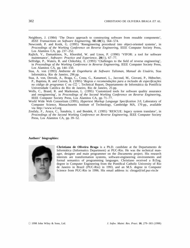
Christiano de Oliveira Braga is a Ph.D. candidate at the Departamento deInformatica (Informatics Department) at PUC-Rio. He was the technical man-ager, designer and main programmer on theDocumentuproject. His researchinterests are transformation systems, software-engineering environments andformal semantics of programming languages. Christiano received a B.Eng.degree in Computer Engineering from the Pontifical Catholic University of Riode Janeiro in Brazil (PUC-Rio) in 1993, and an M.S. degree in ComputerScience from PUC-Rio in 1996. His email address is: cbragaKinf.puc-rio.br
1998 John Wiley & Sons, Ltd. J. Softw. Maint: Res. Pract.10, 279–303 (1998)

303DOCUMENTU
Arndt von Staa is an Associate Professor at the Departamento de Informa´tica(Informatics Department) at the Pontifical Catholic University of Rio de Janeiroin Brazil (PUC-Rio). He designed and developed the software engineeringmeta-environment Talisman. His research interests are software quality andprocess-driven software engineering environments. Currently, he is working onthe design and development of a distributed process-driven meta-environment.Arndt got his Ph.D. in Computer Science from the University of Waterloo inCanada. His email address is: arndtKinf.puc-rio.br
Julio Cesar Sampaio do Prado Leite is an Associate Professor at theDepartamento de Informa´tica (Informatics Department) at the Pontifical CatholicUniversity of Rio de Janeiro in Brazil (PUC-Rio), and the Director of theDraco-PUC project. His research interests are in the areas of reuse, reverseengineering and requirements engineering, where he performed pioneering workon viewpoint analysis. Julio is a member of the IFIP Working Group 2.9 onsoftware requirements engineering, and has served on various internationalprogramming committees, including the IEEE International Conference on Soft-ward Reuse and the IEEE International Symposium on Requirements Engineer-ing. He holds a Ph.D. in Computer Science from the University of California,Irvine. His email address is: julioKinf.puc-rio.br
1998 John Wiley & Sons, Ltd. J. Softw. Maint: Res. Pract.10, 279–303 (1998)