Embed Size (px)
Citation preview

Page
Research Designs & Standards Organisation (Traction Installation directorate)
Reasoned document for the final draft of the Technical Specification No. ETI/PSI/118 (10/93) with A&C slip no. 01 to 11, TI/SPC/PSI/30TRN/2070 with A&C slip no. 01 & TI/SPC/PSI/30TRN/1050 with A&C slip no. 01 -
02 for Single Phase Traction Power Transformer
Only those clauses has been mentioned on which any of the comment has required changes.
1. Comments on the Traction Power Transformer
SN RDSO specification Requirement
Comment of the firm RDSO remarks (Accepted/Not-accepted)
1. Clause no. 13.4 Supply of NIFPES is in the scope of Transformer manufacturer
M/s ABB: We request RDSO to remove supply of NIFPES from the transformer manufacturer SCOPE and that transformer shall have provision of NIFPES system
Not accepted The accessories of a new Traction Transformer are not purchased separately by Indian Railway.
2. Clause no. 16.5.1 Transformer Oil shall be as per IS:12463
M/s ABB: Oil standard 12463 has been cancelled through Gazette notifications and IS:”12463 has been covered in latest IS: 335. We request RDSO to mention oil standard as per latest edition of is: 335.
Accepted RDSO has already changed the standard of oil from 12463 to Type-II of Transformer Oil of IS:335: 2018 and additional requirements mentioned in the letter no. TI/PSI/INSOIL/POLICY/19/01 dated 26/29.07.2019. Same shall be incorporated in the specification
3. Clause no. 3.1.9 Altitude above MSL (max): 1000m
M/s ABB : We request RDSO to mention design guidelines/approval process in case of transformer installation of sites of high altitudes i.e.>1000m (Ref IS standard to be mentioned)
Not Accepted as this specification deals with altitude up to 1000m
4. Clause no. 5.1.10 Overloading
M/s ABB : Overloading conditions of ONAF mode should be clearly mentioned in the specification.
Accepted: Overloading conditions of 150% for 15 minutes for ONAF Mode shall be Incorporated in the specification as this has been followed in the earlier approved designs.
5. Clause no. 13.4 Customer HOLD Points
M/s ABB: RDSO specification should clearly mention Customer Hold Points of various equipment and manufacturing stages of transformer in case of prototype testing.
Accepted: It Shall be mentioned in the specification that at the time prototype approval of transformer, the Customer Hold Points shall be done at following manufacturing stages: (i) OCTC/OLTC (ii) NIFPES. (iii) Transformer Tank (iv) Transformer winding (v) Core assembly Presently, at these manufacturing stages CHP (stage inspection) are being done by RDSO.
6. Clause no. 13.5 Thermosiphon filter
M/s ABB: Thermosiphon filter is not required as air cell type conservator and silica gel breather are being used for avoiding moisture entry into the transformer. Thermosiphon filter system is not used presently as per latest industry practices. Alternatively, maintenance free breather can be used.
Not accepted Air cell and silica gel breather, prevents the contact of moist air with oil in normal level change during temperature variations. There is a possibility of oil in contact with air if any leakage is with any of the gasket, In this case Thermosiphon filter may be required.

Page
7. Clause no. 6.2.1 Bell type tank construction
M/s ABB : We request RDSO to change the tank type to Conventional tank design instead of Bell tank design. According to CBIP Manual on transformers clause 6.1 pg 1, bell tank is recommended for the transformers rating 100MVA and above. In bell tank design, the gasket joint which is at tank bottom side will continuously see excessive oil pressure head and there is high chances oil leakage after few years of operation.
Not accepted The Bell type tank provides the flexibility of visual inspection of assembled core and winding after removing after lifting, transformer tank cover on site. Thus, overhauling/repair on the site. However, in conventional type tank, assembled core and windings are to be lifted for visual inspection.
8. Clause no. 6.5.1 The winding shall be made of continuous electrolytic copper conductor paper insulated to class A insulation.
M/s ABB: Thermally upgraded paper. This will help to reduce ageing rate and increases transformer insulation life. (the differences clearly explained in IEC60076-7 clause 5.6 & 6.0)
Not accepted RDSO specification mention only that “class A insulation paper”, Transformer manufacturers are free to use the Thermally upgraded paper.
9. A&C slip no. 01 to 11 M/s ABB : There are various slips available for each specification. We request RDSO to incorporate slips information in the specifications for better understanding.
Accepted: All the 11 A&C slips and draft of 12 no. also has been merged in the specification as an improvement in the specification.
10. Several specifications M/s ABB : There are various specifications available for single Phase Traction Transformers. We request RDSO to prepare the common specification for single phase Traction Transformer of all ratings.
Accepted: The specifications for 21.6/30.24MVA & 30/42MVA Traction transformer have been combined to make a common specification.
11. Clause no. 12.5.1 Loading capacity of transformers in case of fan failures.
M/s ABB : Please elaborate whether we need to conduct test or provide calculation for loading capacity of transformers in case of fan failures.
Accepted: In the specification it shall be mentioned that the manufacturer shall provide calculation for loading capacity of transformers in case of failure of one or more fans. The ONAF mode in condition of failure of all fans only shall be verified during the temperature rise test for 15minutes.
12. Clause no. 11.0 A separate tapped winding on the secondary winding to give rated secondary voltage for variation in primary voltage of + 10% to -15% , in steps of 5% each
M/s ABB Tapping on HV for HV Variation in
primary voltage of +7 to -9 steps of 1.515% each (CFVV).
Flux density can be fully exploited up to 1.727T which reduces winding turns and active part size.
Load Losses can be reduced from 84kW to 72kW.
Increases reliability due to reducing cross sectional area of the tapping leads which makes easier connections.
This is already implemented in 30/42 MVA Specifications. (Spec no. TI/SPC/PSI/30TRN/2070
Not accepted The firm proposal is better for improvement but it will affect other conditions such as For the 21.6/30.24MVA, if it is implemented, we shall have two designs of Traction Transformers of the same rating in IR. All the approved suppliers have to go through the type testing including short circuit test. At the present conditions of enhanced targeted electrification in the Indian Railways change in the design will delay the targets.
13. Clause no. 11.0 Off Circuit tap Changer
M/s ABB Change to On Load Tap changer No need to de-energize the transformer
while tap changing and in controls voltage on line.
This is already implemented in 30/42 MVA Specifications. (Spec no. TI/SPC/PSI/30TRN/2070)

Page
14. Clause no. 13.4 Testing on the Make of accessories
M/s EMCO: When the transformer manufacturer proposes change in make of OCTC, RDSO declares the unit as a prototype which will be subjected to Type tests & invariably all the stage inspection will be witnessed by RDSO. But there is not point in repeating the stage inspection on NIFPS or OCTC, since NIFPS is an external item which is not affected by transformer design. The OCTC model is the same for any Voltage rating of 21.6/30.24 MVA, may it be 66 KV, 100 KV, 110 KV, 132KV, 220 KV. Only CCA stage inspection & type test i.e. high Voltage tests to be carried out (Pl. Note that the Temperature rise test as per RDSO specification which lasts for 3 days is not required to be carried out since the active part/ core coil assembly is same as before where in all the test were carried out)
Accepted: It may be mentioned in the specification that
1. If a Transformer manufacturer change in the make of OCTC or NIFPES for approved design of transformer with the OCTC or NIFPES which already has been tested by RDSO with another approved transformer, the requirement of CHP may be waived off by RDSO, if supplier declares both are identical.
2. If a Transformer manufacturer change in the make of OCTC for approved design of transformer, the routine testing of the transformer shall be witnessed by RDSO.
15. Clause no. 13.1.8 Buchholz relay: The contacts shall be of mercury switch type, electrically independent and wired upto the marshaling box.
M/s EMCO: Mercury is banned & also because microswitchs help in preventing maloperation of buchholz rely the contacts shall be of micro switch type. M/s KANOHAR: The contacts shall be magnetic switch type, electrically independent and wired up to the marshaling box as Manufacturers have stopped making mercury switch type contact.
Accepted the clause may be modified as: The contacts shall be magnetic switch or micro switch type, electrically independent and wired up to the marshaling box.
16. Annexure-6 of the specification List of makes
M/s EMCO: The lists of makes are obsolete & needs to be updated.
Accepted: List has been deleted from the specification as per the present policy.
17. Clause no. 4.3.1 The short circuit apparent power at the transformer location for various system voltage is as under :- Highest system voltage = 72.5 KV Three phase Short circuit apparent power (MVA) = 3500
M/s KANOHAR :The short circuit apparent power at the transformer location for various system voltage is as under :- Highest system voltage = 72.5 KV Three phase short circuit apparent power (MVA) = 3000 as As per IS 2026 , part-5 , Table 2 (iii) , page no. 2 :- Highest system voltage = 72.5 KV Short circuit apparent power (MVA) = 3000
Not accepted In all the specification Three phase Short
circuit apparent power (MVA) = 3500 has been used for the 72.5kV.
18. Clause no. 5.1.15.2 Ability to withstand short circuit 2) Dynamic ability = 0.5 sec. the duration of each shot shall be 0.5 sec.
M/s KANOHAR: Ability to withstand short circuit:- 2) Dynamic ability = 0.25 sec. the duration of each shot shall be 0.25 sec. As per IS 2026 (Part 5), Clause No. 4.2.5.5, Page No. 8, The duration of each test shall be 0.25 sec. For transformers of Categories II & III. (Category II : 2501 kVA to 100000 kVA)
Accepted As the duration of 0.25 seconds for each shot in the short circuit test is already been mentioned in the specification of 30/42MVA traction Power transformer.
19. Clause no. 6.5.24 The PI value after drying has to be achieved equal to or more than 2(two)
M/s KANOHAR: The PI value after drying has to be achieved more than 1.3 in the manufacturing at the works as As per CBIP, Publication No. 317, Clause No. B.9,
Not accepted The PI value of 2.0 can be achieved during the drying.

Page
in the manufacturing at the works.
Page No. 268:- PI Value will be more than 1.3
20. Annexure-5 Capitalisation of transformer losses: Assuming values of n as 50 years.
M/s KANOHAR: Capitalisation of transformer losses: Assuming values of n as 25 years. As per CBIP, Publication No. 317, Clause No. A(1.0)(iii) of Section AA, Page No. 213:- Life of the transformer (n) : It is taken as 25 years.
Not accepted Indian railway as its own document for the codal life of equipments.
21. Clause no. 5.1.9 Maximum value of % impedance at principle and extreme tap positions:(12+/-0.5)%
M/s TBEA In line with specification for 30/42 MVA, 220/27kV or 132/27kV or 110/27kV or 100/27kV single phase traction power transformer (For use in Mumbai sub-urban area only). Maximum value of % impedence at the principle tap should be (12+/-0.5)%. At extreme taps (Minimum & Maximum),maximum value of % impedence should be (12+/-1.0)% i.e. 11.0% to 13.0%
Not accepted The relaxation in the requirements is not accepted
22. Clause no. 16.3.2 The temperature rise-test
M/s TBEA : Kindly specify in technical specification, Whether these specified overloading conditions are applicable for ONAN / ONAF or both conditions.
Accepted: It shall be clarified in the specification.
23. Clause no. 11.0 Tap Changer
M/s Easun MR: Performance certificate for OCTC which hs been supplied and has been operated in operation for minimum period of five years to be added.
Not Accepted.
24. Clause no. 11.7
Once the tap changing operation has been initiated it must be completed automatically (snap action) even if there is a failure of 110 V dc supply. In case, off -circuit tap - changer with snap action is not readily available, on -load tap changer (without the diverter and other such parts necessary for the on load tap changing), shall be provided so as to have the snap action.
M/s Easun MR
Once the tap changing operation has been initiated and the power supply goes off, OCTC should not stay in between and has to complete the Tap change event once the power supply is restored.
Accepted
25. Suitable legend and schematic diagram plates made of anodised aluminium with black lettering and lines shall be fixed on the inside surface of the cubicle door.
M/s Easun MR
Suitable legend and schematic diagram plates made of stainless steel or anodised aluminium with black lettering and lines shall be fixed on the inside surface of the cubicle door
Accepted
26. Comment on the On load tap changer (specification no. TI/SPC/PSI/30TRN/2070 & TI/SPC/PSI/30TRN/1050).
M/s Easun MR: to add new para OLTC shall be provided with healthiness monitoring system which should monitor Diverter switch operation completion to ensure that under circumstances when the diverter switch has not completed its operation during tap changing process due to any reasons, the system shall be capable to isolate the transformer.
Not accepted at this stage, as any IS/IEC has not been linked with this comment which mentions the comment as a requirement. Also, the method by which the provision shall be ensured and procedure for verification during testing also have not been clarified.

Page
2. COMMENTS ON SPECIFICATION OF NIFPES
Clause no. - (Annexure-I of A&C slip no. 10 of the specification no. ETI/PSI/118)
Para RDSO specification Requirement
Comment of the firm RDSO remarks (Accepted/Not-accepted)
1.0 GENERAL DESCRIPTION: Nitrogen injection fire protection system designed for oil filled transformers prevent tank explosion and the fire during internal faults resulting in an arc, where tank explosion will normally take few seconds after arc generation and also extinguish the external oil fires on transformer top cover due to tank explosion and /or external failures like bushing fires, OLTC fires and fire from surrounding equipments.
M/s Easun MR 1. Replacement of “extinguish” word by “mitigate” word. To add- “The system shall be sensitive to arc faults (to sense the arc generated inside the transformer) and shall be fast acting (response time should be in the order of few seconds).
Not accepted as the “mitigate” word has a synonym “diminish” also. Extinguish word is more justified.
Also, This Para has been modified in the specification as the presence of “arc” word is misinterpreted that the specification has made the “arc sensor” as a requirement.
The system shall consist of following equipments. 1. 2. Fire extinguishing cubicle
placed on a plinth at about 5-10 meter away from the transformer.
M/s Easun MR Replacement of “Fire extinguishing cubicle” word by “switchyard cubicle.” word.
Not Accepted the “Fire extinguishing cubicle” description is more justified with application
M/s CTR: addition in the last “or placed next to fire wall”.
Not accepted as railway substation has the transformer on both side of fire wall (baffle wall)
2. Control box placed in the control room.
M/s Easun MR Control Panel should be with HMI.
Not accepted to make a mandatory requirement as NIFPES does not require regular/frequent human interface.
3. Necessary valves in the conservator pipe.
M/s Easun MR Replacement of “Necessary Valve” word by “Conservator Shutter valve.” word.
The description “Transformer Conservator Isolation valve” is justified with its application and may be used in the specification.
M/s CTR: Replacement of “Necessary Valve” word by “Transformer Conservator Isolation valve.” word.
4. Suitable fire sensing components to be provided preferably in/on the tank cover.
M/s Easun MR Arc sensor mounted on the transformer tank top cover. LHD Cable to be provided preferably in/on the tank cover.
Not accepted: The description ‘Fire detector’ shall be mentioned in the specification. It covers any type of design. Specification does not restrict to any specific make or design.
M/s CTR Required number of fire detectors on the tank top cove
M/s Vendere : “in” to be deleted from the para
Accepted: Sensor should be provided outside the tank only to ensure not interfere with the design of the Transformer.
5. Signal box suitably placed. M/s Easun MR Signal box fitted on the transformer side wall.
Accepted as Signal box fitted on the transformer tank side wall.
M/s CTR: Signal box fitted on the tank side wall.

Page
M/s VISHWAS : to add new para Suitable Arc sensing components to be provided at minimum 4 places inside the transformer tank and 1 in the tap changer tank.
Not accepted : Arc sensor requirement is not a requirement of the specification.
2.0 SCOPE: The scope of this specification covers design, engineering, supply, testing at works before dispatch; erection, testing and commissioning and performance demonstration of “Fire protection and extinguishing system by nitrogen injection method”. The necessary civil work which will be required for construction of oil soak pit for the storage of oil coming out from the transformer and plinth for extinguishing cubicle is outside the scope of this specification.
M/s Easun MR Replacement of “Extinguishing cubicle” word by “switchyard cubicle.” word.
Not Accepted the “Fire extinguishing cubicle” description is more justified with application
However, laying of oil pipe, nitrogen pipe, electrical cables, control boxes, extinguishing cubicle, nitrogen cylinder, necessary valves, fire detectors and other equipments & accessories required for erection, testing, commissioning and performance demonstration of the complete fire protection system is in the scope of the NIFPES tenderer manufacturer. It will be the responsibility of the tenderer, i.e. transformer manufacturer to coordinate with the supplier of the Fire Protection System for all the arrangements for the complete erection, testing, commissioning
and performance tests.
M/s Easun MR However, laying of oil pipe, nitrogen pipe, electrical cables, Control pane with HMI, Switchyard cubicle, Arc sensors, Linear heat detector Cable/other suitable heat/Fire sensor, Nitrogen cylinder necessary valves, fire detectors and other equipments & accessories required for erection, testing, commissioning and performance demonstration of the complete fire protection system is in the scope of the NIFPES tenderer manufacturer. It will be the responsibility of the tenderer, i.e. transformer manufacturer to coordinate with the supplier of the Fire Protection System for all the arrangements for the complete erection, testing, commissioning and performance tests.
Not accepted the Control Panel with HMI to make a mandatory requirement as NIFPES does not require regular/frequent human interface.
Notwithstanding the technical specifications and requirements mentioned herewith any modification can be incorporated for correct operation of nitrogen injection fire protection system without extra cost. The full details of the same are required to be submitted to RDSO for approval, when first unit is implemented on a transformer of specific make & rating.
M/s CTR: addition the para “Modification is not allowed in internal transformer tank design like drilling of holes, welding on transformer tank or inserting any kind of unproven component or sensor in transformer tank, which affects in performance, safety etc or its any other useful parameter for inspection. This requirement shall be paramount importance.”
Not accepted: The transformer tank design is decided by the transformer manufacturer. It is not a part of the NIFPES specification.
M/s Vendere Ambiguity, to be specified in the specifications and to be cleared during approval stage.
Accepted, para shall be removed from the specification to avid ambiguity.
3.0
OPERATIONAL CONTROLS: The system shall be
provided with automatic control for fire prevention and fire extinction. Besides automatic control remote electrical push button control on control box and local manual control in the fire
M/s Easun MR The system shall be provided with automatic control for fire prevention and fire extinction. Besides automatic control remote electrical push button shall be provided in control panel and local manual control panel push button shall be provided in Switchyard panel. The fire protection system will take signal from HV/LV circuit breaker.
Accepted as the a push button in the Switchyard cubicle can also be provided for the electrical operation in case of failure of electrical operation from the Control Box.
Page
extinguishing cubicle shall be provided. The fire protection system will take signal from HV/LV circuit breaker.
M/s CTR The system shall be provided with automatic control for fire prevention and fire extinction. Besides automatic control remote electrical push button /switch control on control box and local manual control in the fire extinguishing cubicle shall be provided.
Not accepted: Push Button can be provided easily.
M/s CTR Provision for spare interlocks is to be provided by system manufacturer for ensuring that it should not be possible to close HV or LV Circuit Breaker to energise the transformer after the activation of fire prevention and fire extinction system.
Not accepted to make a requirement as if the NIFPES operated i.e. oil is drained (10%) the oil low level alarm will always trip the transformer and NIFPES Indication will also be there.
M/s Vender: Push button to be replaced by selector switch
Not accepted: Push Button can be provided easily.
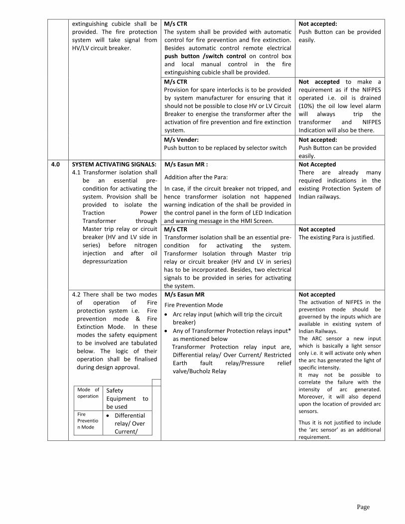
4.0 SYSTEM ACTIVATING SIGNALS: 4.1 Transformer isolation shall
be an essential pre-condition for activating the system. Provision shall be provided to isolate the Traction Power Transformer through Master trip relay or circuit breaker (HV and LV side in series) before nitrogen injection and after oil depressurization
M/s Easun MR :
Addition after the Para:
In case, if the circuit breaker not tripped, and hence transformer isolation not happened warning indication of the shall be provided in the control panel in the form of LED Indication and warning message in the HMI Screen.
Not Accepted There are already many required indications in the existing Protection System of Indian railways.
M/s CTR Transformer isolation shall be an essential pre-condition for activating the system. Transformer Isolation through Master trip relay or circuit breaker (HV and LV in series) has to be incorporated. Besides, two electrical signals to be provided in series for activating the system.
Not accepted The existing Para is justified.
4.2 There shall be two modes of operation of Fire protection system i.e. Fire prevention mode & Fire Extinction Mode. In these modes the safety equipment to be involved are tabulated below. The logic of their operation shall be finalised during design approval.
Mode of operation
Safety Equipment to be used
Fire Prevention Mode
Differential relay/ Over Current/
M/s Easun MR
Fire Prevention Mode
Arc relay input (which will trip the circuit breaker)
Any of Transformer Protection relays input* as mentioned below
Transformer Protection relay input are, Differential relay/ Over Current/ Restricted Earth fault relay/Pressure relief valve/Bucholz Relay
Not accepted The activation of NIFPES in the prevention mode should be governed by the inputs which are available in existing system of Indian Railways. The ARC sensor a new input which is basically a light sensor only i.e. it will activate only when the arc has generated the light of specific intensity. It may not be possible to correlate the failure with the intensity of arc generated. Moreover, it will also depend upon the location of provided arc sensors.
Thus it is not justified to include the ‘arc sensor’ as an additional requirement.

Page
Restricted Earth fault relay.
Pressure relief valve.
Fire Extinction Mode
Fire sensing components.
Buchholz relay
The last Para of the sentence i.e. “The logic of their operation shall be finalised during design approval” may be removed from the operational logic shall be mentioned in the specification.
M/s Easun MR Fire Extinction Mode
Linear Heat Detector/Suitabe Heat/fire Sensor
Any of Transformer Protection relays input* as mentioned below
Transformer Protection relay input are, Differential relay/ Over Current/ Restricted Earth fault relay/Pressure relief valve/Bucholz Relay
Accepted for use of any of the transformer protection relay in series with the fire detector. As once the fire detector has sensed the actual fire, it is better option not to wait for activation of Buchholz relay
M/s CTR,: Fire Prevention:
Differential relay
Buchholz Relay paralleled with Pressure relief valve
Fire Extinction:
Fire detector
Buchholz Relay paralleled with Pressure relief valve
Accepted for use of Buchholz Relay paralleled with Pressure relief valve in prevention mode. As the prevention mode should active in case of formation of gases and increase of pressure both.
M/s VISHWAS
Fire Prevention Mode
Differential relay/Over Current/ Restricted earth faultrelay/Internal arc sensing device.
Pressure relief valve. Fire Extinction Mode
Fire sensing components
Buchholz relay
Not accepted. Reason mentioned in comments of other firms.
M/s Vendere Fire Prevention:
Differential relay/Overcurrent Relay/Restricted earth fault relay
Buchholz Relay paralleled with Pressure relief valve
Fire Extinction:
Fire senescing component
Buchholz Relay paralleled with Pressure relief valve
Accepted for use of Buchholz Relay paralleled with Pressure relief valve in prevention mode. As the prevention mode should active in case of formation of gases and increase of pressure both.
5.0 SYSTEM EQUIPMENT: 5.1 Fire Extinguishing Cubicle
(FEC), placed on plinth at about minimum 5 meter away from the transformer shall consist of:
M/s Easun MR Replacement of “Extinguishing cubicle” word by “switchyard cubicle.” word.
Not Accepted the “Fire extinguishing cubicle” description is more justified with application
5.1.1 Nitrogen gas cylinder with pressure reducer/ regulator and falling pressure electrical contact manometer.
M/s Easun MR Nitrogen gas cylinder with pressure reducer/regulator and pressure gauges for inlet and outlet pressure monitoring. To monitor cylinder pressure digitally, Pressure sensor shall be provided in the system or with the help of falling pressure contact manometer, Nitrogen cylinder pressure low level shall be achieved electrically.
The clause may be modified as below for better understanding in the specification:
Nitrogen gas cylinder with pressure reducer/ regulator.
Necessary gauges shall be provided to monitor the nitrogen cylinder pressure as well as nitrogen injection pressure.
Provision shall be provided for indication in the control
M/s CTR Nitrogen gas cylinder with pressure regulator and falling pressure electrical contact manometer and pressure gauge for monitoring nitrogen injection pressure.

Page
M/s VISHWAS Nitrogen gas cylinder with pressure reducer /regulator and falling pressure electrical contact manometer (Either digital or Analog)
box if the cylinder pressure reduced than specified pressure.
Pressure reducer or pressure regulator and gauges used shall have IP-65 protection.
5.1.2 Oil drain pipe with mechanical quick drain valve.
M/s Easun MR Oil drain pipe with drain valve (shall be butterfly valve type/suitable type)
Comment of the firm is similar with as mentioned in the specification.
5.1.4 Pressure monitoring switch for backup protection, Pressure reducer with solenoid Valve in the cabinet for operation of nitrogen gas release which will be IP-65 protected and leak proof for nitrogen release.
M/s Easun MR Pressure sensor for nitrogen cylinder pressure monitoring and nitrogen leak monitoring. Pressure sensors shall be IP-65 protected Solenoid Valve shall be provided for automatic injection of Nitrogen Gas during auto mode and Manual Nitrogen Injection valve/override also shall be provided for Manual mode.
The comment has been considered in the Para 5.1.1. The provision for Manual mode is already in the specification.
M/s CTR Pressure monitoring switch for backup protection for nitrogen release.
The para “Pressure monitoring switch for backup protection” mentioned in the specification is incomplete. The complete para which is mentioned in the CBIP manual shall be included in the specification.
5.1.6 Flanges on top panel for connecting oil drain and nitrogen injection pipes for transformer.
M/s Easun MR Isolation valves for oil drain and nitrogen injection pipe with necessary flanges shall be provided on top of the switchyard cubicle for connecting oil drain and nitrogen injection pipes with transformer.
Accepted for improvement in the specification.
5.1.7 Panel lighting M/s Easun MR Switchyard cubicle with air vent provision, lightening and heater with built in thermostat. M/s CTR: Panel light using LED
Accepted for improvement in the specification.
5.1.8 Oil drain pipe extension of suitable sizes for connecting pipes to oil pit.
M/s Easun MR Oil drain pipe extension of suitable sizes for connecting pipes to oil pit. These pipes shall be of galvanized iron material
Accepted for improvement in the specification.
5.1.9 The nitrogen gas cylinder should be of sufficient (not less than 50 liter) capacity and should be fitted at a pressure of not less than 150 bars with falling pressure electrical contact manometer. Suitable design measures to prevent leakage of gas to be taken.
M/s Easun MR The nitrogen gas cylinder should be of sufficient (not less than 50 liter) capacity and should be filled at a pressure of not less than 150 bars. Cylinder should be fitted with a Pressure Regulator (with analogue pressure gauges for inlet and outlet pressure monitoring) and a pressure sensor to indicate the cylinder pressure digitally in the control panel HMI Screen. Suitable design measures to prevent leakage of gas to be taken.
Not accepted for modification in this Para. Already these modifications have been mentioned in the above paras.
M/s CTR: (to be placed in technical details para): 10 cubic meter gas at pressure 150kg/sq cm upto 60,000 liters of oil capacity of transformer tank and 2X10=20 cubic meter gas at pressure 150kg/ sq cmm above 60000 liters of oil capacity transformer tank.
Not accepted. Pressure and capacity already defined in the specification. 21.6/30.24 & 30/42MVA Transformer have oil capacity less than 60000 liters.

Page
5.1.10 The nitrogen valve shall
have IP-65 protection. The nitrogen shall be contained within the cylinder and released from the cylinder valve upon activation of fire protection system. Nitrogen purity shall be 99.99%.
M/s Easun MR: The solenoid valve for nitrogen injection shall have IP-65 protection. The nitrogen shall be contained within the cylinder and released from the cylinder valve upon activation of fire protection system. Nitrogen purity shall be 99.99%.
Comments is similar as per the specification
M/s CTR: New par Individual mechanical locking arrangement for nitrogen release as well as oil drain to avoid to avoid unnecessary operation during maintenance and/or testing of transformer and /or system.
Accepted for improvement in the specification.
M/s CTR: New para Individual mechanical release device for oil drain and nitrogen release in case of DC supply failure.
Already manual operation is a part of the specification
M/s CTR: New para Nitrogen release scheme shall be designed in such a way that the nitrogen gas shall not enter the energized transformer even after in case of passing/leakage of valve.
Not accepted, valves provided should be of best quality. The provision of redundancy as a protection over another protection is an endless process.
M/s CTR: New para The oil drain pipe inside the FEC shall have oil leakage detection arrangement for detecting oil leakage from drain valve and necessary indications shall be provided in the control box.
Not accepted. The Low oil level indication/alarm is already provided with the transformer. No need to have additional indications.
M/s CTR: New para Lifting magnets for oil drain and nitrogen injection shall be monitored for healthiness of coil and necessary indications shall be provided in the control box.
Not accepted as this requirement is not justified. Already indications are provided on the control Box as System Healthy.
5.2 Control box with activating, monitoring devices and line faults indicators to be placed in control room. It should have audio visual alarm indication and push button switches for test response.
M/s Easun MR Control panel shall be provided with HMI Screen with data logging provision. Control panel will be placed in the Control room and it shall have audio, visual alarm provisions. It shall have manual push buttons for manual operation, system reset and lamp test operations. All system monitoring, activating and controlling devices shall be placed in the control panel.
No accepted It is not a requirement of data logging or HMI Screen as NIFPES is not a regular requirement, it is an exceptional requirement.
M/s CTR: Control box with activating, monitoring devices including for oil leakage form drain valve, lifting magnet coil monitoring, digital nitrogen cylinder pressure and line faults indicators (to be placed in the control room) . It should have audio visual alarm indication and push button/switches. All individual components shall work on DC supply. AC-DC/DC-DC converter shall not be used for reliable operation.
It cannot be made a requirement that all the equipments of the NIFPES should work on Sub Station DC Voltage. However, the main Input requirement as per Sub Station Voltage has already been defined in the specification.

Page
5.3 Necessary valves to be fitted in the conservator pipe line, between conservator and buchholz relay operating mechanically on transformer oil flow rate with electrical signal for monitoring.
M/s Easun MR Conservator shutter valve to be fitted in the conservator pipe line, between conservator and buchholz relay. Conservator shutter valve shall be designed to operate mechanically with respect to oil flow rate and provide electrical signal for monitoring. It shall also have one more electrical output to indicate the conservator shutter valve status when it is put in “circulation mode”
Not accepted to make a part of specification for having one more contact or indication which is not a requirement.
M/s CTR Transformer Conservator Isolation valve: (TCIV) to be fitted horizontally in the conservator pipe line, between conservator and buchholz relay operating mechanically on transformer oil flow rate (without using any kind of spring type action) with electrical signal for monitoring. Shall operate for isolating the conservator during abnormal flow of oil due to rupture/explosion of the tank or bursting of busing or tank oil drain depressurization during system operation. TCIV shall be provided with oil filling/refilling/filter locking position so that TCIV will not isolate conservator during flow of oil during filling or refilling or filtration, locking plates shall be provided with handle for padlocking to ensure no movement of valve position during filling/refilling/filtration position. It shall have proximity switch for remote alarm and indication transparent window for visual inspection similar to buchholz transparent window for physical checking o the status of valve.
Not accepted as the requirements mentioned in the specification are sufficient.
5.4 Suitable Fire sensors to
be fixed on transformer tank top cover and Off Circuit Tap Changer for sensing fire.
M/s Easun MR Linear Heat Detector Cable/Suitable Heat/Fire Sensors to be laid on Transformer top cover and on Off circuit Tap changer for the effective monitoring of the temperature. Linear Heat Detector/Heat /Fire Sensors should sense the transformer body temperature all along the tank surface for the effective sensing. These sensors should be laid on the Transformer top cover in such a way that the sensor must be in contact with the Transformer body for the effective heat sensing. Heat/Fire Sensor should have the activation temperature of 138 +/- 3% / 141+/-2 Deg.
Not accepted
The description ‘fire detectors’ which is mentioned in the specification is correct. It covers any type of design. Specification should not restrict to any specific make or design.
M/s CTR Fire detectors (quartz bulb) to be fixed on transformer tank top cover and On load/Off Circuit Tap Changer for sensing fire.
5.5 Signal box to be fixed on transformer side wall for terminating cable connections from fire sensors and conservator
M/s Easun MR Signal Box shall be mounted on Transformer wall, where cable connections from Arc Sensor, Linear Heat Detector / Heat/Fire Sensor and Conservator Shutter Valve will be terminated
Clause may be modified as : Signal box fitted on the transformer tank side wall for terminating cable connections from fire sensing component and TCIV.

Page
shutter/ signal box to be suitably placed.
M/s CTR Signal Box to be fixed on Transformer side wall for terminating cable connections from fire detectors and TCIV.
5.6 All other consumables necessary for operation of complete system.
M/s Easun MR All other consumable necessary for correct functioning of the system
Not accepted, specification description is sufficient.
5.7 Control Box should be microprocessor based and compatible to be interfaced with existing RTU for railway traction SCADA system available at the control room. For communication Control Box shall have provision for interfacing with SCADA in this regards details Digital Input & output required for operation monitoring through SCADA should be furnished
M/s CTR Control box shall be provided with potential free contact namely, system operated, cylinder pressure low, DC supply fail, System in auto mode, for interfacing with Railway RTU for railway traction SCADA system. Details of potential free contact shall be submitted.
Not accepted
Microprocessor based Control box is the requirement of the specification.
M/s Easun MR Control box should be Microprocessor /Microcontroller based and compatible to be interfaced with existing RTU system available at Railway Traction SCADA system. For communication, Control panel shall have provision for the interfacing with Railway Traction SCADA system. in this regards details of Digital Input & Output (MODBUS Mapping details) required for the interface to be furnished
The clause in the specification may be modified as below: Control Box should be microprocessor based compatible to be interfaced with existing RTU for railway traction SCADA system. For communication with SCADA Control Box shall have provision for interfacing with RTU through RS485 over MODBUS protocol. (As requirement mentioned in the clause no. 5.3.3.1 of the SCADA specification.) Following indications of NIFPES are to be interfaced with SCADA: NIFPES active. Status of NIFPES i.e. in
Auto/Manual/OFF position.
NIFPES system is healthy
M/s VISHWAS Control Box should be microprocessor based and compatible to be interfaced with existing RTU for Railway Traction SCADA system along with data logger facility available at the control room. For communication Control box shall have provision for interfacing with SCADA in this regards details Digital Input &Output required for operation monitoring through SCADA should be furnished.
6.0 OTHER REQUIREMENTS FOR SYSTEM INSTALLATION: 6.1 Oil drain and nitrogen
injection openings with gate valves on transformer tank at suitable locations.
M/s Easun MR Oil Drain and Nitrogen Injection openings with Gate Valves (of suitable sizes) on transformer tank at suitable locations.
Accepted It is only description modification
6.2 Flanges with dummy piece in conservator pipe between Buchholz relay and conservator tank for fixing.
M/s Easun MR Flanges with dummy piece In Conservator pipe between Bucholz relay and Conservator tank for fixing Conservator Shutter Valve
Clause may be modified as below for improvement: Flanges with dummy piece in conservator pipe between Buchholz relay and conservator tank for fixing TCIV.
M/s CTR Flanges with dummy piece in conservator pipe between Buchholz relay and conservator tank for fixing TCIV.
M/S TSPL: add after tha para Flanges provided in transformer should be square in size.
Not accepted, the reason for mentioning square size only as a requirement is not justified.

Page
6.3 Brackets on transformer top cover for sensing equipment, valves to be enable operation of the system.
M/s Easun MR Arc Sensor mounting provision to be provided on transformer top cover (as per the drawing provided) Linear Heat Detector laying pads with brackets/Heat/Fire Sensor mounting brackets to be provided (as per the provided drawing) for the correct functioning of the system
Comments not accepted. Specification does not restrict to any make or design.
M/s CTR Fire detector Brackets on transformer top cover.
M/s CTR: New Para Mounting support/frame on tank side wall for signal box.
Accepted as an improvement
6.5 Pipe connections between transformer to fire extinguishing cubicle and fire extinguishing cubicle to oil pit.
M/s Easun MR Pipe connections between transformer to Switchyard Cubicle and Switchyard Cubicle to oil pit.
Not accepted already mentioned.
M/s CTR: Pipe connections between transformer to fire extinguishing cubicle using necessary flexible bellows and fire extinguishing cubicle to oil pit.
Not accepted; The pipe connections can be made by supplier by their standard practices
6.6 Cabling on transformer top cover all sensors to be suitably connected for reliable fire sensing and inter cabling between signal box to control box and control box to fire extinguishing cubicle.
M/s Easun MR Cabling for all Arc Sensors and Heat/Fire Sensors should be suitably done for the effective Arc and Heat sensing. Also interconnection cabling between Signal box to Control panel and Control panel to Switchyard panel should be suitably done for the correct functioning of the system
Not accepted Already mention.
M/s CTR: Cabling on transformer top cover all fire detectors to be connected in parallel and inter cabling between signal box to control box and control box to fire extinguishing cubicle.
6.7 Plinth for fire extinguishing cubicle. Oil pit with capacity as 10 % of total oil quantity of transformer.
M/s Easun MR In order to place the Switchyard panel, plinth shall be constructed as per the given drawing. In order to collect the drained oil upon activation of the system, oil-pit should be constructed with a capacity of at least 10% of the total transformer oil volume.
Accepted as an improvement in the specification.
7.0 TECHNICAL DETAILS:
On system activation up-to post cooling : Maximum 3 minutes
M/s Easun MR On system activation – Maximum 3 Minutes
Not Accepted. Post cooling description to avoid the re ignition
Fire detectors heat sensing temperature : 140 ± 2
0 C
M/s Easun MR Linear Heat detector/Heat/Fire sensor sensing temperature – 138Deg.C +/-3% / 141+/- 2Deg.C
Not accepted The temperature shall be mentioned as per the requirements M/s CTR: Fire detectors (quartz bulb) heat
sensing temperature : 1410 C
Setting for operate to isolate conservator : min. 60 ltr. per minute
M/s Easun MR Conservator Shutter Valve activation flow rate – 60LPM to 90 LPM
Accepted for specifying a limit for verification during testing.

Page
Power Source: Control Box : 110 V DC Fire extinguishing cubicle for lighting : 240 V AC
M/s Easun MR Control Box : 110 V DC Fire extinguishing cubicle for lighting & Heater : 240 V AC
Accepted
M/s CTR Control Box : As per substation DC voltage or 110 V DC Fire extinguishing cubicle for lighting: 240 V AC
Not accepted
M/s VENDERE 240 V AC to be replaced by 230V AC
Not Accepted
8.0 CABLING:
8.1 Fire survival cables, able to withstand 750
0C, 1.5 mm
sq with necessary no. of Conductors for connection of fire detectors in parallel shall be used. The test certificates for the cables shall be submitted.
M/s Easun MR Arc Sensors, Linear Heat Detector/Heat/Fire Sensors, Conservator shutter Valves are should be wired till Signal box with Fire Survival Cable, who’s withstanding temperature, shall be 750 Deg.C. Cable conductor cross section shall be 1.5 Sq.mm with necessary number of conductors for the correct functioning of the system. Test certificates for the cables shall be submitted.
Not Accepted: The description mentioned in the Para is justified and correct.
M/s CTR Fire survival cables, able to withstand 750
0C, 4
core X1.5 mm sq for connection of fire detectors in parallel shall be used. The test certificates for the cables shall be submitted.
8.2 Fire retardant low smoke (FRLS) cable 1.5 mm sq. with necessary no. of Conductors for connection between transformer signal box/ marshaling box to control box and control box to fire extinguishing cubicle shall be used.
M/s Easun MR Signal box/Marshaling Box to Control panel interconnection wiring should be done with FRLS armoured cable with 1.5sq.mm conductor cross section.
Not accepted: The description mentioned in the Para is justified and correct.
M/s CTR Fire retardant low smoke (FRLS) cable 12core X 1.5 mm sq. for connection between transformer signal box/ marshaling box to control box and control box to fire extinguishing cubicle shall be used.
8.3 Fire retardant low smoke (FRLS) 1.5 mm sq. with necessary no. of Conductors for connection between control box to DC supply source and fire extinguishing cubicle to AC supply source, signal box/ marshaling box on transformer shall be used.
M/s Easun MR Interconnection between Switchyard panel to Control panel and Control and Relay panel to Control panel should be done with FRLS cable with conductor cross section 1.5sq.mm. Number of cores in the cable can be selected in such a way that the correct wiring should be ensured for the proper functioning of the system.3 Core FRLS cable with 1.5 Sq.mm conductor cross section shall be used for feeding AC supply to Heater and lighting circuits and 2 core FRLS cable with 1.5 Sq.mm cable can be used for providing Panel supply voltage.
Not accepted: The description mentioned in the para is justified and correct.
M/s CTR Fire retardant low smoke (FRLS) 4core X 1.5 mm sq. for connection between control box to DC supply source and fire extinguishing cubicle to AC supply source, signal box / marshaling box to pre-stressed non-return valve connection on transformer shall be used.
Not accepted: The description mentioned in the para is justified and correct.

Page
9.0 PREVIOUS EXPERIENCE FOR QUALIFYING SUPPLIER: The supplier shall have a minimum experience of two years in the design, manufacturing, erection, testing and commissioning of nitrogen injection fire protection system on power transformers of similar or higher rating. At least 2 sets of the system shall be in successful operation for a minimum period of the 2 years. The supplier shall furnish the details of nitrogen injection fire protection systems supplied by them so far, giving order reference, name and address of the customer, indicating the dates of commissioning as well as performance certificate of successful and satisfactory operation for minimum two years from the customers.
M/s Easun MR This clause is encouraging monopolism. Further RDSO has left to the choice of choosing any component vendor to the Transformer manufacturer. The same choice should be left for NIFPS as well. This will encourage more transparent competition and better Technology and pricing.
Not accepted:
The NIFPES is not a new technology, that the suppliers cannot have experience. Specification does not encourage monopolism. The Traction Power transformer is the main safety equipment of Traction Sub Station. The damage due to fire in the transformer will lead to the complete outage of the substation and may take a number of days for rectification resulting in the disturbance in traffic movement in addition to loss of property and life. Thus the supplier of NIFPES shall have experience as per the specification
M/s VISHWAS This clause should be removed as NIFPES is not a complex system but just merely an assembly product, the prerequisite e should only be suitable type Test of the System at Recognized laboratorial
M/s CTR The supplier shall have a minimum experience of five years in the design, manufacturing, erection, testing and commissioning of nitrogen injection fire protection system on power transformers of similar or higher rating. At least 2 sets of the system shall be in successful operation for a minimum period of the 3 years. The supplier shall furnish the details of nitrogen injection fire protection systems supplied by them so far, giving order reference, name and address of the customer, indicating the dates of commissioning as well as performance certificate of successful and satisfactory operation for minimum two years from the customers.
Not accepted;
The required experience has already been mentioned in the specification.
M/s Vendere The supplier shall have a minimum experience of five years in the design, manufacturing, erection, testing and commissioning of nitrogen injection fire protection system on power transformers of similar or higher rating. At least 2 sets of the system shall be in successful operation for a minimum period of the 3 years. The supplier shall furnish the details of nitrogen injection fire protection systems supplied by them so far, giving order reference, name and address of the customer, indicating the dates of commissioning as well as performance certificate of successful and satisfactory operation for minimum three years from the customers.
Not accepted;
The required experience has already been mentioned in the specification.
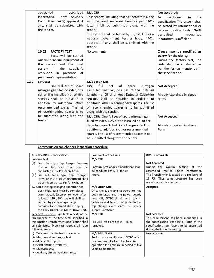
10.0 TESTS 10.1 TYPE TESTS
Type test reports including that for detectors along with declared response time as per test approval certificate letter shall be submitted along with the tender. The system shall be tested by international or national testing body (NABL
M/s Easun MR NIFPS performance should be tested with real Electrical arc at any of the recognized laboratories.
Not accepted:
The Input required for the activation of NIFPES is mentioned in the specification.
M/s TSPL: add after para Factory Test (mfg.) test report should be accepted.
Not accepted: In Factory RDSO shall witness. The third part report is additional requirement
M/s Vendere: TAC does not exists TAC may be removed from the Para.
Page
accredited recognized laboratory). Tariff Advisory Committee (TAC’s) approval, if any, shall be submitted with the tender.
M/s CTR Test reports including that for detectors along with declared response time as per TAC’s letter shall be submitted along with the tender. The system shall be tested by UL, FM, LPC or a national government testing body. TAC’s approval, if any, shall be submitted with the tender.
Not accepted:
As mentioned in the specification The system shall be tested by international or national testing body (NABL accredited recognized laboratory) is sufficient
10.02 FACTORY TEST Tests will be carried
out on individual equipment of the system and the total system in the supplier’s workshop in presence of purchaser’s representative.
No comments Clause may be modified as below for the clarity: During the factory test, The tests shall be conducted as per the format mentioned in the specification.
12.0 SPARES: One full set of spare
nitrogen gas filled cylinder, one set of the installed no. of fire sensors shall be provided in addition to additional other recommended spares. The list of recommended spares is to be submitted along with the tender.
M/s Easun MR One full set of spare Nitrogen gas filled Cylinder, one set of the installed length/ no. Of Liner Heat Detector Cable/fire sensors shall be provided in addition to additional other recommended spares. The list of recommended spares is to be submitted along with the tender.
Not Accepted: Already explained in above paras
M/s CTR: One full set of spare nitrogen gas filled cylinder, 50% of the installed no. of fire detectors (quartz bulb) shall be provided in addition to additional other recommended spares. The list of recommended spares is to be submitted along with the tender.
Not Accepted: Already explained in above Paras
Comments on tap changer inspection procedure
As in the RDSO specification: Comment of the firms RDSO Comments
Pressure test:
(i) For in tank type tap changer: Pressure test on top head cover shall be conducted at 12 PSI
for six hour.
(ii) For out tank type tap changer: Pressure test of oil compartment shall be conducted at 12 PSI for six hours.
M/s CTR Pressure test of oil compartment shall be conducted at 5 PSI for six hours.
Not Accepted During the routine testing of the assembled Traction Power Transformer, The Transformer is tested at a pressure of 12 PSI. Thus same pressure has been mentioned at this test also.
2.7 Once the tap changing operation has been initiated it must be completed automatically (snap action) even after failure of 110 V DC supply. It shall be verified by giving a tap change command and immediately tripping the 110V DC MCB in Motor Drive Unit.
M/s Easun MR: Once the tap changing operation has been initiated and the power supply goes off, OCTC should not stay in between and has to complete to the tap change event once the power supply is restored.
Accepted
Type tests reports: Type tests reports of the tap changer of the type tests specified in the Traction Transformer Specification shall be submitted. Type test repot shall have following tests: (i) Temperature rise test of contacts. (ii) Mechanical endurance test. (iii) Milli - volt drop test. (iv) Short circuit current test. (v) Dielectric test (vi) Auxiliary circuit Insulation tests
M/s CTR (iii) Milli - volt drop test. - To be removed.
Not accepted This requirement has been mentioned in the specification since initial issue of the specification, test report to be submitted during the in-house testing.
M/s EASUN MR Performance certificate of OCTC which has been supplied and has been in operation for a minimum period of five years to be added.
Not accepted
Page
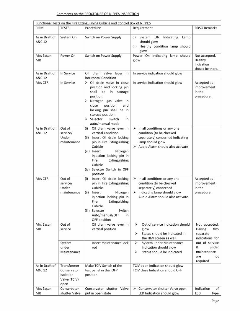
Comments on the PROCEDURE OF NIFPES INSPECTION
Functional Tests on the Fire Extinguishing Cubicle and Control Box of NIFPES
FIRM TESTS Procedure
Requirement RDSO Remarks
As in Draft of A&C 12
System On Switch on Power Supply (i) System ON Indicating Lamp should glow
(ii) Healthy condition lamp should glow
M/s Easun MR
Power On Switch on Power Supply Power On Indicating lamp should glow
Not accepted. Healthy indication should be there.
As in Draft of A&C 12
In Service Oil drain valve lever in horizontal Condition
In service indication should glow
M/s CTR In Service Oil drain valve in close position and locking pin shall be in storage position.
Nitrogen gas valve in close position and locking pin shall be in storage position.
Selector switch in auto/manual mode
In service indication should glow Accepted as improvement in the procedure.
As in Draft of A&C 12
Out of service/ Under maintenance
(i) Oil drain valve lever in vertical Condition
(ii) Insert Oil drain locking pin in Fire Extinguishing Cubicle
(iii) Insert Nitrogen injection locking pin in Fire Extinguishing Cubicle
(iv) Selector Switch in OFF position
In all conditions or any one condition (to be checked separately) concerned Indicating lamp should glow
Audio Alarm should also activate
M/s CTR Out of service/ Under maintenance
(i) Insert Oil drain locking pin in Fire Extinguishing Cubicle
(ii) Insert Nitrogen injection locking pin in Fire Extinguishing Cubicle
(iii) Selector Switch Auto/manual/OFF in OFF position
In all conditions or any one condition (to be checked separately) concerned
Indicating lamp should glow Audio Alarm should also activate
Accepted as improvement in the procedure.
M/s Easun MR
Out of service
Oil drain valve lever in vertical position
Out of service indication should glow
Status should be indicated in the HMI screen as well
Not accepted. Having two separate indications for out of service & under maintenance are not required.
System under Maintenance
Insert maintenance lock rod
System under Maintenance indication should glow
Status should be indicated
As in Draft of A&C 12
Transformer Conservator Isolation Valve (TCIV) open
Make TCIV Switch of the test panel in the ‘OFF’ position.
TCIV open Indication should glow TCIV close Indication should OFF
M/s Easun MR
Conservator shutter Valve
Conservator shutter Valve put in open state
Conservator shutter Valve open LED Indication should glow
Indication of LED type

Page
open Status should be indicated in the HMI screen as well
accepted.
As in Draft of A&C 12
Transformer Conservator Isolation Valve (TCIV) closed
Make TCIV Switch of the test panel to ‘ON’ position.
TCIV closed Indication should glow
TCIV open Indication should OFF Audio Alarm should activate
M/s CTR Transformer Conservator Isolation Valve (TCIV) closed
Make TCIV Switch of the test panel to ‘ON’ position.
TCIV closed Indication should glow
TCIV open Indication should OFF Audio Alarm should activate Healthy condition Indication
should go off
Accepted as improvement
M/s Easun MR
Conservator shutter Valve closed
Conservator shutter Valve put in closed state
Conservator shutter Valve closed LED Indication should glow
Status should be indicated in the HMI screen as well
Indication of LED type accepted.
As in Draft of A&C 12
Fire detector Activation
Activate the signal on test panel
Fire detector trip Indication lamp should glow.
Healthy condition Indication lamp should go OFF
Audio Alarm should activate
Deactivate the signal on test panel
Healthy condition Indication lamp should turn ON
Fire detector trip Indication lamp should go OFF.
M/s CTR Fire detector Activation
Activate the Fire detector signal on test panel
Fire detector trip Indication lamp should glow.
Healthy condition Indication lamp should go OFF
Audio Alarm should activate
Accepted as correction in draft
Deactivate the Fire detector signal on test panel
Healthy condition Indication lamp should turn ON
Fire detector trip Indication lamp should go OFF.
M/s Easun MR
Linear heat Detector (LHD) Activation
Short the two terminals of the linear heat detector
LHD Activation LED should glow. Status should be displayed in HMI
Screen as well. Extinction Mode LED should glow Audio Alarm will activate
Not accepted, already explained in specification clauses.
Remove the shorting link of LHD
LHD Activation LED should goes off.
HMI Screen warning message should goes off.
Extinction Mode LED should goes off.
Audio Alarm should go off.
As in Draft of A&C 12
Bucholz relay trip
Activate the signal on test panel
Bucholz relay trip Indication lamp should glow.
Healthy condition Indication lamp should OFF
Audio Alarm should activate
Deactivate the signal on test panel
Healthy condition Indication lamp should turn ON
Bucholz relay trip Indication lamp should go OFF.
M/s CTR Bucholz relay trip
Activate the bucholz relay signal switch on test panel
Bucholz relay trip Indication lamp should glow.
Healthy condition Indication lamp should OFF
Audio Alarm should activate
Accepted as correction
Deactivate the signal on test Healthy condition Indication

Page
panel lamp should turn ON Bucholz relay trip Indication lamp
should go OFF.
M/s Easun MR
Bucholz relay Protection Input
NC potential free contact input of Bucholz relay should be given
Bucholz relay protection LED should glow
Status should be displayed in HMI screen as well
Requirement of HMI Not accepted
Deactivate Bucholz relay protection Input
Bucholz relay protection LED should goes off.
No warning message n HMI Screen.
As in Draft of A&C 12
Oil drain valve open.
Open Oil Drain Valve in Fire Extinguishing Cubicle Manually. (Oil drain valve lever in vertical condition)
Oil drain valve open Indication lamp should glow.
Healthy Condition Indicating lamp should OFF
Audio Alarm should activate
M/s CTR Oil drain valve open
Open Oil Drain Valve in Fire Extinguishing Cubicle Manually. (Oil drain valve lever in vertical condition)
Oil drain valve open Indication lamp should glow.
Healthy Condition Indicating lamp should OFF
Audio Alarm should activate
------
M/s Easun MR
Oil drain valve open.
Keep the Oil drain valve flap in vertical position
Oil drain valve open LED should glow.
Status should be displayed in HMI screen as well
Requirement of HMI Not accepted
As in Draft of A&C 12
Oil drain valve closed
Close Oil Drain Valve in Fire Extinguishing Cubicle Manually. (Oil drain valve lever in horizontal condition)
Healthy Condition Indication lamp should ON.
Oil drain valve closed Indication lamp should glow.
M/s CTR Oil drain valve closed
Close Oil Drain Valve in Fire Extinguishing Cubicle Manually. (Oil drain valve lever in horizontal condition)
Healthy Condition Indication lamp should go ON.
Oil drain valve closed Indication lamp should glow.
--------
M/s Easun MR
Oil drain valve closed.
Keep the Oil drain valve flap in horizontal position
Oil drain valve closed LED should glow.
No warning message in HMI Screen
Requirement of HMI Not accepted
As in Draft of A&C 12
Extinction in progress
Operate nitrogen release device in Fire Extinguishing Cubicle manually.
Extinction in progress Indication lamp should glow.
Healthy condition Indication lamp should OFF
Audio Alarm should activate
M/s CTR Extinction in progress
Operate nitrogen release device in Fire Extinguishing Cubicle manually.
Extinction in progress Indication lamp should glow.
Healthy condition Indication lamp should OFF
Audio Alarm should activate
-----
M/s Easun MR
Extinction Mode
Activate LHD Extinction mode LED should glow. Status should be displayed in HMI
screen as well. Audio Alarm should activate
Requirement of HMI Not accepted
As in Draft of A&C 12
Gas Inlet valve closed
Close nitrogen release device in Fire Extinguishing Cubicle manually
Healthy condition Indication lamp should ON
Gas Inlet valve closed Indicating lamp should glow.
M/s CTR Gas Inlet valve closed
Close nitrogen release device in Fire Extinguishing Cubicle manually
Healthy condition Indication lamp should ON
Gas Inlet valve closed Indicating
------

Page
lamp should glow.
M/s Easun MR
Nitrogen valve closed
Nitrogen Injection solenoid valve in de energized condition
Nitrogen valve closed LED should glow.
Requirement of HMI Not accepted
Nitrogen valve opened
Nitrogen Injection solenoid valve in energized condition
Nitrogen valve open LED should glow. Status should be displayed in HMI screen as well
As in Draft of A&C 12
Nitrogen Gas Cylinder pressure low (Nitrogen Gas leaking)
Adjust contact on manometer below the specified pressure.
Cylinder pressure low Indication lamp should glow.
Healthy condition Indication lamp should OFF
Audio Alarm should activate
M/s CTR Nitrogen Gas Cylinder pressure low
Adjust contact on manometer below the specified pressure.
Cylinder pressure low Indication lamp should glow.
Healthy condition Indication lamp should OFF
Audio Alarm should activate
M/s Vendere kg/mm2 to be corrected as kg/cm2
Accepted as correction
M/s TSPL 50kg/cm2 Shall be as per spec
M/s Easun MR
Nitrogen Cylinder pressure low
i) Set the Hooter Activation for Nitrogen cylinder Pressure Low in the HMI screen -120Bar.
ii) Allow the cylinder pressure reads by the pressure sensor 1 to drop down below 120 Bar
Nitrogen cylinder pressure low Indication lamp should glow.
Status should be displayed in the HMI Screen
Audio Alarm should activate
Not accepted
Nitrogen leak detection
Through Manual over ride option, allow the Nitrogen to leak through Solenoid Valve
Nitrogen leak detection LED lamp should glow.
Status should be displayed in the HMI Screen
Audio Alarm should activate
Accepted
As in Draft of A&C 12
Differential relay trip/ Over Current Relay (OCR) Trip/ Restricted Earth Fault (REF) relay trip
(i) Activate the trip signal on test panel
Relay trip Indicating lamp should glow.
Healthy condition Indication lamp should OFF
Audio Alarm should activate
Deactivate the trip signal on test panel
Healthy condition Indication lamp should turn ON Relay trip Indicating lamp should go OFF.
Pressure Relief valve (PRV) Trip
(i) Activate the signal on test panel
PRV trip Indicating lamp should glow.
Healthy condition Indication lamp should OFF
Audio Alarm should activate
(ii) Deactivate the signal on test panel
Healthy condition Indication lamp should turn ON
PRV trip Indicating lamp should go OFF.

Page
M/s VISHWAS POWER
Differential relay trip/ Over Current Relay (OCR) Trip/ Restricted Earth Fault (REF) relay trip/Arc sensor trip
Activate the trip signal on test panel
Relay trip Indicating lamp should glow.
Healthy condition Indication lamp should OFF
Audio Alarm should activate
Tests shall be mentioned as per the logic mentioned in the specifications
Deactivate the trip signal on test panel
Relay trip Indicating lamp should go OFF.
Healthy condition Indication lamp should ON
M/s CTR Separately tests for Differential Relay, Over current relay and restricted earth fault relay
Separately tests for Differential Relay, Over current relay and restricted earth fault relay
Tests shall be mentioned as per the logic mentioned in the specifications
M/s Easun MR
Differential relay protection
NC Potential free contact input of differential Relay should be given
Differential relay protection LED should be glow.
Status should be displayed in the HMI Screen
Tests shall be mentioned as per the logic mentioned in the specifications
Remove the differential relay input
Differential relay protection LED should go off.
No warning message in HMI Screen
Overcurrent relay protection
NC Potential free contact input of Overcurrent Relay should be given
Overcurrent relay protection LED should be glow.
Status should be displayed in the HMI Screen
Tests shall be mentioned as per the logic mentioned in the specifications
Remove the Overcurrent relay input
Overcurrent relay protection LED should go off.
No warning message in HMI Screen
Restricted earth fault relay protection
NC Potential free contact input of Restricted earth fault Relay should be given
Restricted earth fault relay protection LED should be glow.
Status should be displayed in the HMI Screen
Remove the Restricted earth fault relay input
Restricted earth fault relay protection LED should go off.
No warning message in HMI Screen
PRV protection
NC Potential free contact PRV should be given
PRV protection LED should be glow.
Status should be displayed in the HMI Screen
Remove the PRV input PRV protection LED should go off. No warning message in HMI
Screen
As in Draft of A&C 12
HVCB Open
Activate HVCB ‘ON’ signal on test panel
No Change
M/s CTR HVCB Open
To be deleted To be deleted Not accepted verification for system status on tripping of separate breakers required

Page
M/s Easun MR
HVCB ON
NC Potential free contact input of CB status monitoring coil should be given
HVCB ON LED indication should be glow.
Status should be displayed in the HMI Screen
As in Draft of A&C 12
LVCB Open
Activate LVCB ‘ON’ signal on test panel
No Change
M/s CTR LVCB Open
To be deleted To be deleted Not accepted verification for system status on tripping of separate Breakers required
M/s Easun MR
LVCB ON
NC Potential free contact input of CB status monitoring coil should be given
LVCB ON LED indication should be glow.
Status should be displayed in the HMI Screen
May be finalized as per the specification
As in Draft of A&C 12
HVCB Open & LVCB Open (Transformer trip)
(i) Activate both ‘HVCB’ & ‘LVCB’ ON signal on the test panel
Transformer Isolation indicating lamp should glow.
Healthy condition Indication lamp should OFF
Audio Alarm should activate.
Reset both signals Healthy condition Indication lamp should turn ON Transformer Isolation indicating lamp should go OFF.
M/s CTR Transformer Isolation
Activate the transformer isolation switch on the test panel
Transformer Isolation indicating lamp should glow.
Healthy condition Indication lamp should OFF
Audio Alarm should activate
Not accepted, Specification is more clear
M/s Easun MR
Master CB Trip
CB Trip Coil NC input given Master CB Trip LED indication should be glow.
Status should be displayed in the HMI Screen
May be finalized as per the specification
Remove CB Trip Coil input Master CB Trip LED indication should go off.
No warning message in HMI Screen
As in Draft of A&C 12
DC Supply fail
Switch OFF DC Supply to Control Box
DC Supply Fail indication should glow
Audio Alarm should activate
M/s CTR
DC Supply fail
Switch OFF DC Supply to Control Box
DC Supply Fail indication should glow
Audio Alarm should activate
-------
M/s Easun MR
DC Supply fail
Switch OFF DC Supply in Control panel (F3 MCB)
All LED indication should go off. DC supply failed LED Indication
should glow. Status should be displayed in the
HMI Screen

Page
As in Draft of A&C 12
System test for prevention mode (Auto mode)
a) Activate following signals:
i. HVCB & LVCB Open ii. Differential relay/ Over
Current relay/ Restricted Earth Fault relay trip
iii. Pressure Relief Valve trip
TCIV should close Oil Drain valve should open Nitrogen gas should release Audio Alarm should activate. Following Indication lamps should
glow -Prevention Mode ON -TCIV close -Oil drain valve open -Nitrogen Gas release
Healthy Condition Indication lamp should go OFF.
M/s VISHWAS POWER
System test for prevention mode (Auto mode) iii. Pressure Relief Valve trip
a) Activate following signals: i. HVCB & LVCB Open ii. Differential relay/ Over Current relay/ Restricted Earth Fault relay trip/arc sensor trip
TCIV should close Oil Drain valve
should open Nitrogen gas should release Audio Alarm should activate Following
Indication lamps should glow
Prevention Mode O
TCIV close
Oil drain valve open
Nitrogen Gas release
Healthy Condition Indication lamp should go OFF.
May be finalized as per the specification
M/s TSPL
Pressure monitoring switch should also be indicated
Not accepted. Required indications are already mentioned.
M/s CTR System test for prevention mode (Auto mode)
Activate following signals:
i. Differential relay trip AND
ii. Pressure Relief Valve
trip AND
iii. Transformer Isolation
i. Oil Drain valve should open ii. Nitrogen gas should release iii. Audio Alarm should activate. iv. Following Indication lamps
should glow -Prevention Mode ON -Oil drain valve open -Nitrogen Gas release (Extinction in progress)
v. Healthy Condition Indication lamp should go OFF.
May be finalized as per the specification TCIV should be closed before oil drain valve open, thus TCIV should close indication is required.
M/s Easun MR
Auto Prevention mode
i) Presence of Arc ii) Any of transformer Fault Input iii) Master CB Trip
feedback
Arc relay Activated Master CB trip Oil Drain valve should open Shutter Valve should close Nitrogen gas should release HMI screen should display system
status and receipt of respective input signals
Corresponding LED Indicating lamps should glow (Power On, Out of service, auto Mode, master CB trip, respective transformer Protection relay Input LED, Arc detection, Prevention Mode, Oil drain valve open, Nitrogen valve open)
Audio Alarm
May be finalized as per the specification
Page
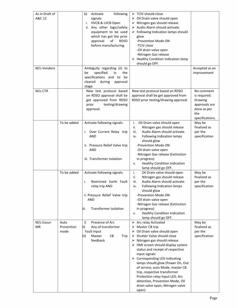
As in Draft of A&C 12
b) Activate following signals:
i. HVCB & LVCB Open ii. Any other logic/safety
equipment to be used which has got the prior approval of RDSO before manufacturing.
TCIV should close Oil Drain valve should open Nitrogen gas should release Audio Alarm should activate. Following Indication lamps should
glow -Prevention Mode ON -TCIV close -Oil drain valve open -Nitrogen Gas release
Healthy Condition Indication lamp should go OFF.
M/s Vendere Ambiguity regarding (ii) to be specified in the specifications and to be cleared during approval stage.
Accepted as an improvement
M/s CTR New test protocol based on RDSO approval shall be get approved from RDSO prior testing/drawing approval.
New test protocol based on RDSO approval shall be get approved from RDSO prior testing/drawing approval
No comment is required. Drawing approvals are done as per the specifications.
To be added Activate following signals:
i. Over Current Relay trip AND
ii. Pressure Relief Valve trip
AND iii. Transformer Isolation
i. Oil Drain valve should open ii. Nitrogen gas should release iii. Audio Alarm should activate. iv. Following Indication lamps
should glow -Prevention Mode ON -Oil drain valve open -Nitrogen Gas release (Extinction in progress)
v. Healthy Condition Indication lamp should go OFF.
May be finalized as per the specification
To be added Activate following signals:
i. Restricted Earth Fault relay trip AND
ii. Pressure Relief Valve trip
AND
iii. Transformer Isolation
i. Oil Drain valve should open ii. Nitrogen gas should release iii. Audio Alarm should activate. iv. Following Indication lamps
should glow -Prevention Mode ON -Oil drain valve open -Nitrogen Gas release (Extinction in progress)
v. Healthy Condition Indication lamp should go OFF.
May be finalized as per the specification
M/s Easun MR
Auto Prevention mode
i) Presence of Arc ii) Any of transformer Fault Input iii) Master CB Trip
feedback
Arc relay Activated Master CB trip Oil Drain valve should open Shutter Valve should close Nitrogen gas should release HMI screen should display system
status and receipt of respective input signals
Corresponding LED Indicating lamps should glow (Power On, Out of service, auto Mode, master CB trip, respective transformer Protection relay Input LED, Arc detection, Prevention Mode, Oil drain valve open, Nitrogen valve open)
May be finalized as per the specification

Page
Audio Alarm
As in Draft of A&C 12
System test for Extinction mode (Auto mode)
Activate following signals: i. HVCB & LVCB Open ii. Fire Sensing
Component trip iii. Bucholz relay trip
TCIV should close Oil Drain valve should open Nitrogen gas should release Audio Alarm should activate. Following Indication lamps should
glow -Prevention Mode ON -TCIV close -Oil drain valve open -Nitrogen Gas release
Healthy Condition Indication lamp should go OFF.
M/s Vendere TCIV to be remove since TCIV works independtly on oil flow and does not work on logic during system operation.
Accepted
M/s CTR System test for Extinction mode (Auto mode)
Activate following signals: i. Fire detected trip AND ii. Bucholz relay trip AND iii. Transformer Isolation
Oil Drain valve should open Nitrogen gas should release Audio Alarm should activate. Following Indication lamps should
glow -Prevention Mode ON -Oil drain valve open -Nitrogen Gas release
Healthy Condition Indication lamp should go OFF.
May be finalized as per the specification
M/s Easun MR
Auto extinguishing mode
i) Linear heat (LHD) activation
ii) Bucholz relay input iii) Master CB Trip
feedback
LHD Activation Master CB trip Oil Drain valve should open Shutter Valve should close Nitrogen gas should release HMI screen should display system
status and receipt of respective input signals
Corresponding LED Indicating lamps should glow (Power On, Out of service, auto Mode, master CB trip, Bucholz relay Input LED, LHD Activation Extinguishing Mode, Oil drain valve open, Nitrogen valve open)
Audio Alarm
May be finalized as per the specification
As in Draft of A&C 12
System test for Extinction mode in REMOTE MANUAL Electrical mode on Control Box
Activate following signals: i. Mode Selection switch
in manual mode ii. Press Manual Extinction
Operation Push Button to ON in control cubicle.
HVCB & LVCB should Open TCIV should close Oil Drain valve should open Nitrogen gas should release Audio Alarm should activate. Following Indication lamps should
glow -Prevention Mode ON -TCIV close -Oil drain valve open -Nitrogen Gas release
Healthy Condition Indication lamp should go OFF.
M/s Vendere System test for Extinction mode in REMOTE MANUAL Electrical
Push Button to be removed by Selector switch
TCIV to be removed Not accepted. Push button can be provided.

Page
mode on Control Box
M/s CTR System test for Extinction mode in REMOTE MANUAL Electrical mode on Control Box
Activate following signals: i. Mode Selection
(Auto/Manual/OFF) switch in manual mode
ii. Press Manual Extinction Operation Push Button to ON in control box.
Oil Drain valve should open Nitrogen gas should release Audio Alarm should activate. Following Indication lamps should
glow -Oil drain valve open -Nitrogen Gas release (Extinction in progress)
Healthy Condition Indication lamp should go OFF.
Accepted.
M/s Easun MR
Manual Extinction in REMOTE Electrical MANUAL mode in Control Panel
i) Select the Mode selection Switch to manual mode
ii) Press manual operation push button in control panel
Master CB trip Oil Drain valve should open Shutter Valve should close Nitrogen gas should release HMI screen should display system
status and receipt of respective input signals
Corresponding LED Indicating lamps should glow (Power On, Out of service, manual Mode, master CB trip, Extinction Mode, Oil drain valve open, Nitrogen valve open)
Audio Alarm
May be finalized as per the specification
As in Draft of A&C 12
System test for Extinction mode in Local manual control on Fire Extinguishing Cubicle (To be used in case of d.c. supply failure)
To be done on Fire Extinguishing Cubicle i. Push lever for Oil drain. ii. Push Lever for Nitrogen
gas release.
Oil Drain valve should open Nitrogen gas should release
M/s CTR
System test for
Extinction mode in Local manual control on Fire Extinguishing Cubicle (To be used in case of d.c. supply failure)
To be done on Fire Extinguishing Cubicle i. Push lever for Oil drain. ii. Push Lever for Nitrogen
gas release.
Oil Drain valve should open Nitrogen gas should release
M/s Easun MR
Manual Extinction in Local MANUAL mode in Switchyard
i) Select the Mode selection Switch to manual mode
ii) Press manual operation push button in switchyard cubicle
Master CB trip Oil Drain valve should open Shutter Valve should close Nitrogen gas should release HMI screen should display system
status and receipt of respective input signals
Corresponding LED Indicating lamps should glow (Power On, Out of service, manual Mode, master CB trip, Extinction Mode, Oil drain valve open, Nitrogen valve open)
Audio Alarm
May be finalized as per the specification
Manual Extinction in Local
i) Hold the manual operation Knob.
ii) Pull the chain
No Indications
May be finalized as per the

Page
Mechanical MANUAL mode
iii) Operate the Manual Nitrogen Release vale
specification
As in Draft of A&C 12
Panel Lighting
Switch on 240V AC supply in fire extinguishing cubicle
Panel Lights should be in working condition.
M/s Vendere 240V to be replaced by 230V
Not accepted
M/s CTR Panel Lighting
Switch on 240V AC supply in fire extinguishing cubicle
Open door of fire extinguishing cubicle
Fire extinguishing cubicle Lights should be in working condition when door is open.
Accepted as improvement
M/s Easun MR
Panel Lighting
Switch on 240V AC supply in fire extinguishing cubicle
Panel Lights should be in working condition.
Accepted as
improvement
Heater Heater Heater switch be turned on in the switchyard cubicle for the input 240V AC
Accepted as
improvement
As in Draft of A&C 12
High voltage test to be separately done on Control Box and Signal Box
Apply 2kV AC for 1 minute between terminal bar and Box body
Should withstand.
M/s CTR High voltage test to be separately done on Control Box and Signal Box
Apply 2kV AC for 1 minute between terminal bar and Box body
Should withstand.
M/s Easun MR
High voltage test to be separately done on Control Box and Signal Box
Apply 2kV AC for 1 minute between terminal bar and Box body
Should withstand.
As in Draft of A&C 12
Communication with SCADA
Check for the Digital Input/ Output provided on NIFPES system for communicating with SCADA.
The Control Box shall be compatible to be interfaced with SCADA.
M/s CTR Communication with SCADA
Check for the potential free contact provided on NIFPES system for communicating with SCADA.
The Control Box shall be compatible to be interfaced with SCADA.
May be finalized as per the specification
M/s Easun MR
Communication with SCADA
Check for the Digital Input/ Output provided on NIFPES system for communicating with SCADA.
The Control Box shall be compatible to be interfaced with SCADA.
May be finalized as per the specification
Conservator Shutter Valve Locked
Keep the Rotary Selector Switch knob in the Conservator Shutter valve in Circulation Mode
Conservator shutter valve locked LED should glow
Status should be displayed in HMI Screen as well
AC supply failed
Switch off the AC supply inn Control Panel (F1 MCB)
AC supply failed LED should glow. Status should be displayed in
HMI Screen as well
Auto operation Failed
i) Close the Nitrogen Cylinder and ensure not sufficient Nitrogen gas pressure in the Regulator outlet
ii) Activate the system for nitrogen injection
Auto operation failed LED should glow.
Status should be displayed in HMI Screen as well
ARC Detection
Deactivate ARC detector
Auto detection LED should glow. Status should be displayed in
HMI Screen as well
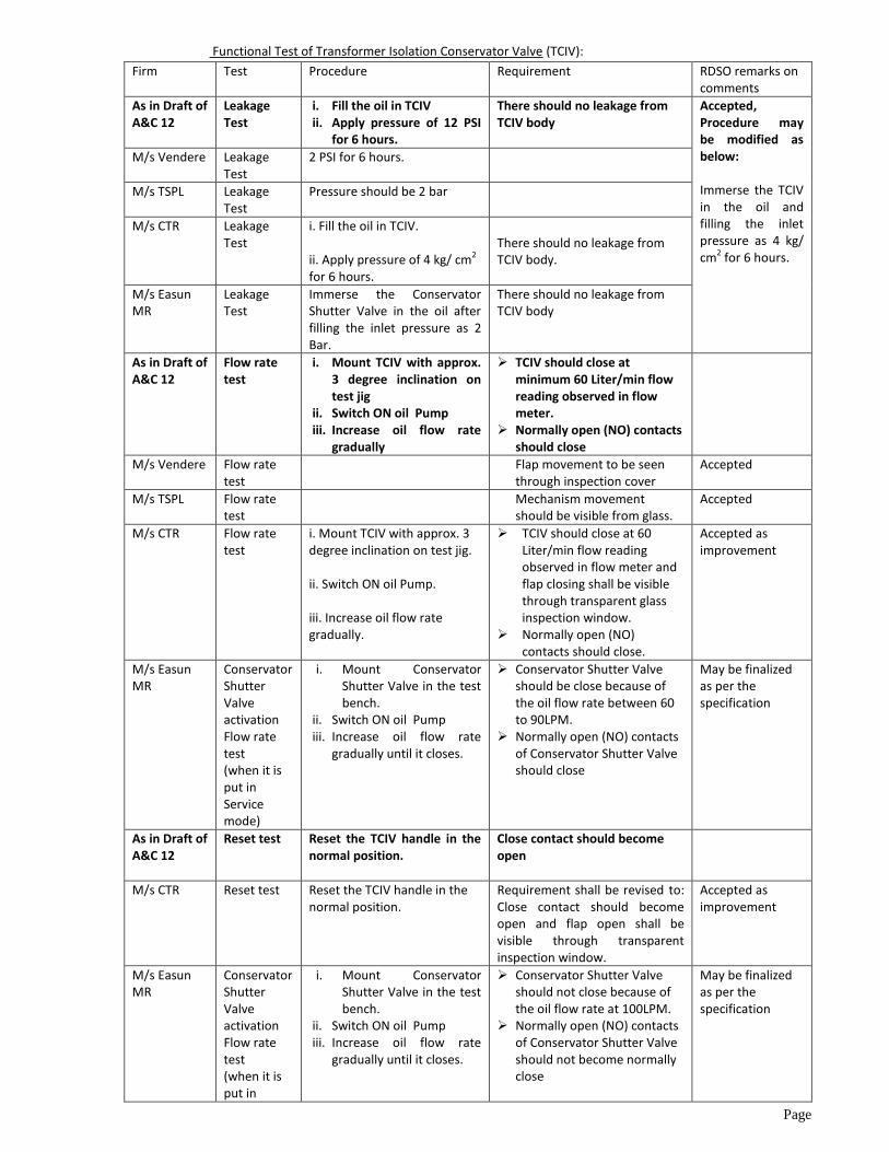
Page
Functional Test of Transformer Isolation Conservator Valve (TCIV):
Firm Test Procedure Requirement RDSO remarks on comments
As in Draft of A&C 12
Leakage Test
i. Fill the oil in TCIV ii. Apply pressure of 12 PSI
for 6 hours.
There should no leakage from TCIV body
Accepted, Procedure may be modified as below: Immerse the TCIV in the oil and filling the inlet pressure as 4 kg/ cm2 for 6 hours.
M/s Vendere Leakage Test
2 PSI for 6 hours.
M/s TSPL Leakage Test
Pressure should be 2 bar
M/s CTR Leakage Test
i. Fill the oil in TCIV. ii. Apply pressure of 4 kg/ cm2 for 6 hours.
There should no leakage from TCIV body.
M/s Easun MR
Leakage Test
Immerse the Conservator Shutter Valve in the oil after filling the inlet pressure as 2 Bar.
There should no leakage from TCIV body
As in Draft of A&C 12
Flow rate test
i. Mount TCIV with approx. 3 degree inclination on test jig
ii. Switch ON oil Pump iii. Increase oil flow rate
gradually
TCIV should close at minimum 60 Liter/min flow reading observed in flow meter.
Normally open (NO) contacts should close
M/s Vendere Flow rate test
Flap movement to be seen through inspection cover
Accepted
M/s TSPL
Flow rate test
Mechanism movement should be visible from glass.
Accepted
M/s CTR Flow rate test
i. Mount TCIV with approx. 3 degree inclination on test jig. ii. Switch ON oil Pump. iii. Increase oil flow rate gradually.
TCIV should close at 60 Liter/min flow reading observed in flow meter and flap closing shall be visible through transparent glass inspection window.
Normally open (NO) contacts should close.
Accepted as improvement
M/s Easun MR
Conservator Shutter Valve activation Flow rate test (when it is put in Service mode)
i. Mount Conservator Shutter Valve in the test bench.
ii. Switch ON oil Pump iii. Increase oil flow rate
gradually until it closes.
Conservator Shutter Valve should be close because of the oil flow rate between 60 to 90LPM.
Normally open (NO) contacts of Conservator Shutter Valve should close
May be finalized as per the specification
As in Draft of A&C 12
Reset test Reset the TCIV handle in the normal position.
Close contact should become open
M/s CTR Reset test Reset the TCIV handle in the normal position.
Requirement shall be revised to: Close contact should become open and flap open shall be visible through transparent inspection window.
Accepted as improvement
M/s Easun MR
Conservator Shutter Valve activation Flow rate test (when it is put in
i. Mount Conservator Shutter Valve in the test bench.
ii. Switch ON oil Pump iii. Increase oil flow rate
gradually until it closes.
Conservator Shutter Valve should not close because of the oil flow rate at 100LPM.
Normally open (NO) contacts of Conservator Shutter Valve should not become normally close
May be finalized as per the specification

Page
Circulation mode)
As in Draft of A&C 12
High voltage test
Apply 2kV AC for 1 minute between terminals and body
TCIV should withstand.
M/s CTR
High voltage test
Apply 2kV AC for 1 minute between terminals and body
TCIV should withstand. -----
M/s Easun MR
Insulation Resistance Test
Apply 2kV AC for 1 minute between conservator shutter valve electrical output contact terminals and its body
Conservator shutter valve should withstand the applied 2kV for 1 minute.
May be finalized as per the specification
Functional test on Fire Sensing Component:
SN Test Procedure Requirement RDSO remarks
As in Draft of A&C 12
Heat Sensing Temperature & Heat Sensing area
i. The fire sensing component shall be placed in an isothermal enclosure of minimum 800 mm radius.
ii. Minimum 04 nos. of temperature sensor shall be placed at 800 mm radii from the fire sensing component.
iii. The temperature of the isothermal enclosure shall be increased gradually.
The temperature of the all the temperature sensors shall be 140±2°C when the fire sensing component activates.
M/s Vendere This is a special test and not routine test. As such, test report from fire laboratory (who follows international standard) to be referred and considered.
Accepted: Third party report from a national testing body (NABL accredited recognized laboratory) shall be accepted.
M/s TSPL
It requires more time to prepare test facility at present, it can be verified on the basis of the test certificate
M/s CTR Considering special test, third party report from international /
M/s Easun MR
Activation Temperature test
i. LHD cable of length 300mm kept inside a muffle furnace.
ii. Temperature of the muffle Furnace allowed increasing gradually till 138 degree Celsius.
LHD should diffuse and make short circuit at 138+/- 3%
Live demonstration test in Auto Fire Extinguishing Mode:
Procedure:
As per RDSO Draft Comments of the firms RDSO remarks
The Fire Sensing component shall
be mounted on the Transformer
tank.
M/s EASUN MR: Linear Heat detector shall be mounted on the Transformer tank.
Not accepted: Already explained spec mention Fire Sensing component.
All the necessary pipe connections
shall be made between
Transformer Tank to Switchyard
Cubicle.
M/s CTR: The Fire Extinguishing Cubicle , Control box, test panel, oil pit with all necessary pipes and cable connections shall be connected with transformer tank
Accepted as improvement in procedure
The Control Box and Signal Box should also be connected
M/s EASUN MR Interconnection between Control Panel, Switchyard
cubicle and Signal Box suitably made.
Accepted as improvement in procedure

Page
Digital Storage Oscilloscope shall
be used for the measurement of
activation time of system.
Following Inputs shall be
connected to the different
channels of storage Oscilloscope.
(a) Fire sensing component
activation
(b) Oil drain valve latch
activation
(c) Nitrogen valve open
(Nitrogen Injection started)
(d) Nitrogen valve closed
(Nitrogen injected )
M/s EASUN MR Digital Storage Oscilloscope shall be used for the measurement of activation time of system. Following Inputs shall be connected to the different channels of storage Oscilloscope.
(a) LHD activation (b) Oil drain valve activation (c) Nitrogen valve open (Nitrogen Injection
started) (d) Nitrogen valve closed (Fire quenched )
----------
M/s CTR: Stop watch shall be used for :
a. System activation
b. Commencement of nitrogen injection. c. Fire extinction
Accepted. The requirements shall be modified in the specification. M/s TSPL: Timing should be seen on the stop watch
M/s VENDERE 1. Connectivity to channels to not suitable 2. (d)not applicable since valve remains open
The Bucholz Relay Trip and HVCB
& LVCB Trip Signal shall be
activated by test panel.
M/s CTR The NIFPS system shall be made ON by
activating signal as per clause 4.0 by test panel.
Shall be as per the specification
M/s EASUN MR Activate Bucholz Relay input to control panel
Activate HVCB & LVCB or Master CB Trip Feedback
to Control Panel.
Shall be as per the specification
The Transformer Oil Temperature
shall be raised up to 140±2 degree
Celsius.
M/s EASUN MR Ignite Transformer tank oil to catch fire.
Accepted as all comments are same M/s CTR
Transformer oil in tank put on fire having minimum opening of 900 mm say 132kV bushing turret size.
M/s Vendere Transformer tank should be put on fire with opening
of bushing
M/s CTR
The NIFPS system shall be made ON by activating signal as per clause 4.0 of the specification
The verification is in extinguishing mode. The input shall be used as per the specification
Observations:
Requirement as draft of
spec
Comments of the firms RDSO remarks on the
comment
At 140±2 degree Celsius
the system should activate.
M/s EASUN MR Due to the fire, LHD laid on Transformer cover will get
heated up and it will diffuse at 138+/- 3% Degree Celsius
and give its input to control panel.
As above the put fire has
been accepted, this clause
shall be removed.
Nitrogen should be
injected after a preset
duration.
M/s EASUN MR Nitrogen should be injected after 5S.
Shall be finalized as per
the specification
M/s CTR: i. Oil drain started
ii. Nitrogen injection should start immediately only after oil
drains start.

Page
Following Indications has been turned ON: (a) Oil Drain valve
open (b) Nitrogen gas
release (c) Audio Alarm
activated (d) Extinction in
Progress (e) System ON (f) LVCB & HVCB Trip (g) Buchholz Relay
trip (h) Fire Detector ON (i) Healthy Condition
Indication lamp should be OFF
M/s EASUN MR Following Indications has been turned ON: (a) Oil Drain valve opened (b) Nitrogen valve opened (c) Audio Alarm activated (d) Extinction in Progress (e) System ON (f) Master CB Trip (g) Buchholz Relay trip (h) LHD Activation (i) Out of service
Not accepted, Shall be as per the specification
M/s CTR Following indications shall be turn ON: (a) Oil drain valve open (b) Extinction in progress. (c) Buchholz relay trip. (d) HV CB & LV CB / Master relay trip. (e) Audio alarm shall be activated
Calculation of time with graphs saved in Digital Storage Oscilloscope
RDSO requirement Comments RDSO remarks
Oil Drain Valve Opening time (T1) =
Time of Fire sensing component
activation – Oil Drain valve latch
activation
M/s EASUN MR Oil Drain Valve Opening time (T1) = LHD activation –
Oil Drain valve latch activation
------------
Time taken for Fire Extinction on commencement of Nitrogen Injection (T2) = Time of Nitrogen Injection Valve open – time of nitrogen Injection valve close
M/s EASUN MR Time taken for Fire Extinction on commencement of
Nitrogen Injection (T2) = Time of Nitrogen Injection
Valve opening time – time of nitrogen Injection valve
closing time
----------------
Total time Period for Fire Extinction on
system activation up to post cooling
(T3) = Oil Drain Valve Opening time (T1)
+ Preset Nitrogen Injection delay
(decided by NIFPES manufacturer) +
Time taken for Fire Extinction on
commencement of Nitrogen Injection
(T2)
M/s EASUN MR Total time Period for Fire Extinction on system
activation up to post cooling (T3) =
Oil Drain Valve Opening time (T1) + Preset Nitrogen Injection delay (5s) + Time taken for Fire Extinction on commencement of Nitrogen Injection (T2)
-----------------
Results of Fire extinction period: On commencement of Nitrogen Injection (T2) : Maximum ……seconds On system activation up to post cooling (T3): Maximum …… minutes
M/s CTR Fire should quench in maximum 30 seconds on commencement of nitrogen injection.
Shall be as per the specification
M/s TSPL: We ensure that there should be no re ignition
In addition to the tests at the works of NIFPES manufacturer, following test certificates/details shall also
be submitted during inspection of NIFPES:
RDSO specification Comments RDSO remarks
Type, make, and quantity of Fire Sensing Component being used with actual Railway Transformer.
M/s Easun MR comment: Type, make, and length of LHD Cable being used with actual Railway Transformer.
Documents shall be sought as per the finalized specification.
M/s CTR comment: Type, make and quantity shall be approved during drawing approval. Hence submission not applicable during inspection
M/s TSPL : It should be done during approval stage

Page
IP-65 protection certificate of the pressure reducer from international or a national testing body (NABL accredited recognized laboratory).
M/s Easun MR comment: IP-65 protection certificate of the pressure reducer from OEM.
Documents may be sought by RDSO at any stage.
M/s CTR comment: Shall be approved during drawing approval. Hence submission not applicable during inspection.
Type, make and quantity of the fire survival cable (750°C, 1.5 mm sq.) used for connection of fire sensors/detectors and test report of the cable reflecting withstands temperature.
M/s Easun MR comment: Type, make and length of LHD Cable fire survival cable (750°C, 1.5 mm sq.) used for connection of LHD cable, arc sensor and conservator shutter valve and test report of the cable reflecting withstands temperature.
M/s CTR comment: Type, make and quantity of fire survival cable used for connection of fire detectors in parallel shall be approved during drawing approval. Hence submission not applicable during inspection.
Test report for 750°C, 1.5 mm sq. may be verified during inspection
M/s TSPL : It should be done during approval stage
Type and make of the FRLS cable 1.5mm sq. used for connection among transformer signal box/marshaling box/control box/fire extinguishing cubicle along with Cable Manufacturer’s Test Certificate.
M/s Easun MR comment: Type and make of the FRLS cable 1.5mm sq. used for connection among transformer signal box/marshaling box/control box/fire extinguishing cubicle along with Cable Manufacturer’s Test Certificate.
M/s CTR comment: Type is FRLS. Make shall be approved during drawing approval. Hence submission not applicable during inspection
for FRLS cable 1.5mm sq. used for connection among transformer
signal box / marshaling box /control box/fire extinguishing cubicle /DC source /AC source. Cable Manufacturer’s Test Certificate may be verified during inspection.
M/s TSPL : It should be done during approval stage
Type test report of the NIFPES along with the response time. Type test report shall be of system tested by international or a national testing body (NABL accredited recognized laboratory). NABL certificate of the testing agency shall also be submitted
M/s Easun MR comment: Type test report of the NIFPES along with the response time. Type test report shall be done at NABL accredited recognized laboratory and NABL certificate of the testing agency.
Type test report of the NIFPES performance validation by creating a Real Electrical ARC inside the Transformer tank. Type test report shall be done at NABL accredited recognized laboratory and NABL certificate of the testing agency.
M/s CTR comment: No international standard is available for type test. Test report shall be approved during drawing approval. Hence submission not applicable during inspection.
Customer’s Performance certificate for at least 2 sets of the system which has been supplied and has been in operation for a minimum period of two years. The certificate shall be verified with issuing authority.
M/s Easun MR comment : Performance certificate for at least 2 sets of the system which has been supplied and has been in operation for a minimum period of two years.
M/s CTR comment : Shall be approved during drawing approval. Hence submission not applicable during inspection.
Necessary calculation regarding adequacy of the number of cylinders provided and nitrogen release pressure for the operation of the NIFPES system in actual Railway Transformer.
M/s Easun MR comment : Necessary calculation regarding adequacy of the number of cylinders provided and nitrogen release pressure for the operation of the NIFPES system in actual Railway Transformer
M/s CTR comment : Shall comply clause 5.1.9 of technical specification regarding cylinder capacity and pressure and approve during drawing approval stage. Hence submission not applicable during inspection.
Cylinder certificate may be verified during inspection.