Embed Size (px)
Citation preview

Research Background
Nonlinear Control of Electro-Mechanical Systems
Design AnalysisExperimental
Validation
Robot Manipulators
- Constrained robots- Electrically driven robots- Flexible joint robots
MagneticBearings
Flexible MechanicalSystems (PDE)
AerospaceSystems
- Formation Flying- Attitude Control- VTOL
Nonlinear Control of Multiple Spacecraft Flying in
Formation
Dr. Marcio S. de Queiroz
Outline
Multiple Spacecraft Formation Flying (MSFF) Concept
Dynamic Model
Nonlinear Control
Simulation Results
Fuel Consumption Issue
Ongoing and Future Research

MSFF Concept
Distribute the functionality of a large spacecraft among an array of highly-coordinated, autonomous micro-spacecraft (“Virtual spacecraft”)
Large, specialized spacecraft
Virtual spacecraft
Earth
MSFF Concept
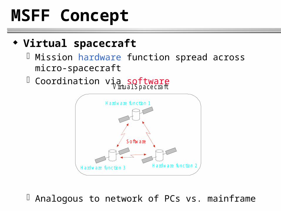
Virtual spacecraft Mission hardware function spread across micro-spacecraft Coordination via software
Analogous to network of PCs vs. mainframe
Hardware function 1
Virtual Spacecraft
Hardware function 2Hardware function 3
Software
MSFF Concept
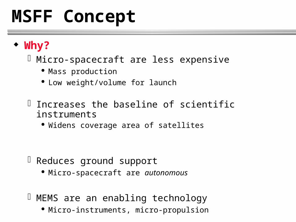
Why? Micro-spacecraft are less expensive
Mass production Low weight/volume for launch
Increases the baseline of scientific instruments Widens coverage area of satellites
Reduces ground support Micro-spacecraft are autonomous
MEMS are an enabling technology Micro-instruments, micro-propulsion

MSFF Concept
Why? (cont.) Flexible architecture
Robustness, redundancy, and reconfigurability
Minimizes effects of failure
Multi-mission capability
Reduces mission cost and increases performanceReduces mission cost and increases performance
E arth
Com municationm ission
Radar m ission
Fleet augm entation and/orreplacement
Radiom etry m ission
Spacecraft failure
MSFF Concept
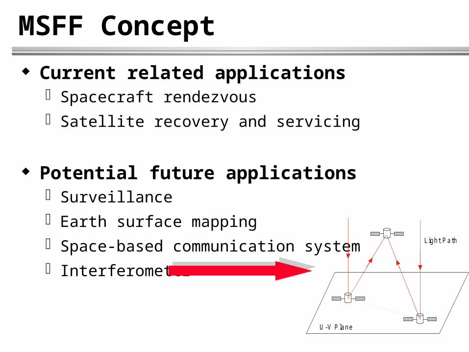
Current related applications Spacecraft rendezvous
Satellite recovery and servicing
Potential future applications Surveillance
Earth surface mapping
Space-based communication system
Interferometer
U -V P lane
Light Pa th
MSFF Concept
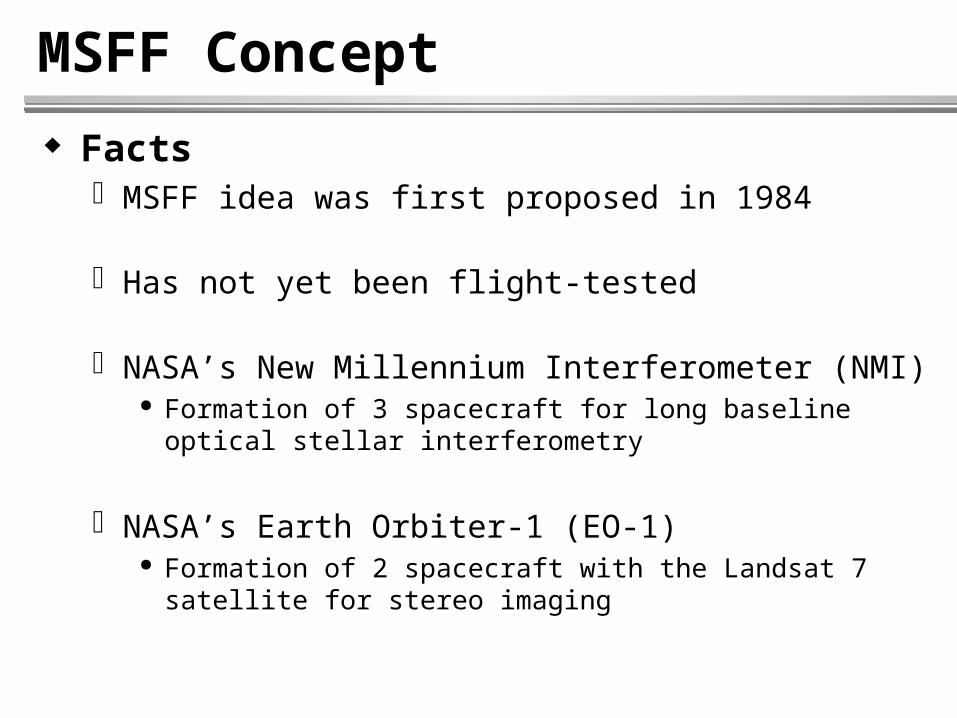
Facts MSFF idea was first proposed in 1984
Has not yet been flight-tested
NASA’s New Millennium Interferometer (NMI) Formation of 3 spacecraft for long baseline optical stellar
interferometry
NASA’s Earth Orbiter-1 (EO-1) Formation of 2 spacecraft with the Landsat 7 satellite for stereo
imaging
MSFF Concept
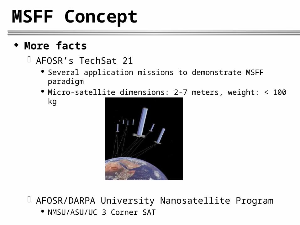
More facts AFOSR’s TechSat 21
Several application missions to demonstrate MSFF paradigm Micro-satellite dimensions: 2-7 meters, weight: < 100 kg
AFOSR/DARPA University Nanosatellite Program NMSU/ASU/UC 3 Corner SAT

Researchers are exploring methods to … use midget spacecraft - some weighing less than a pound and hardly larger than a pack of cards - that could be used alone to perform simple tasks or flown in formations to execute more complex ones.
… next month … the Air Force launches a fleet of tiny … satellites made of miniature components - diminutive machines that could … work together in groups to replace or supplement larger spacecraft.
“We’re talking about fully integrated satellites that could be mass produced cheaply by the hundreds and sent into space to perform a of variety tasks.”
If one or several of the machines in a formation fails, others in the group could redistribute themselves and the continue performing the same task ...
Peter Panetta of NASA’s Goddard SpaceFlight, agrees, saying there is a growing interest in increasingly smaller … spacecraft. “This isn’t just a fad. A lot of people see this as the future …”
MSFF Concept
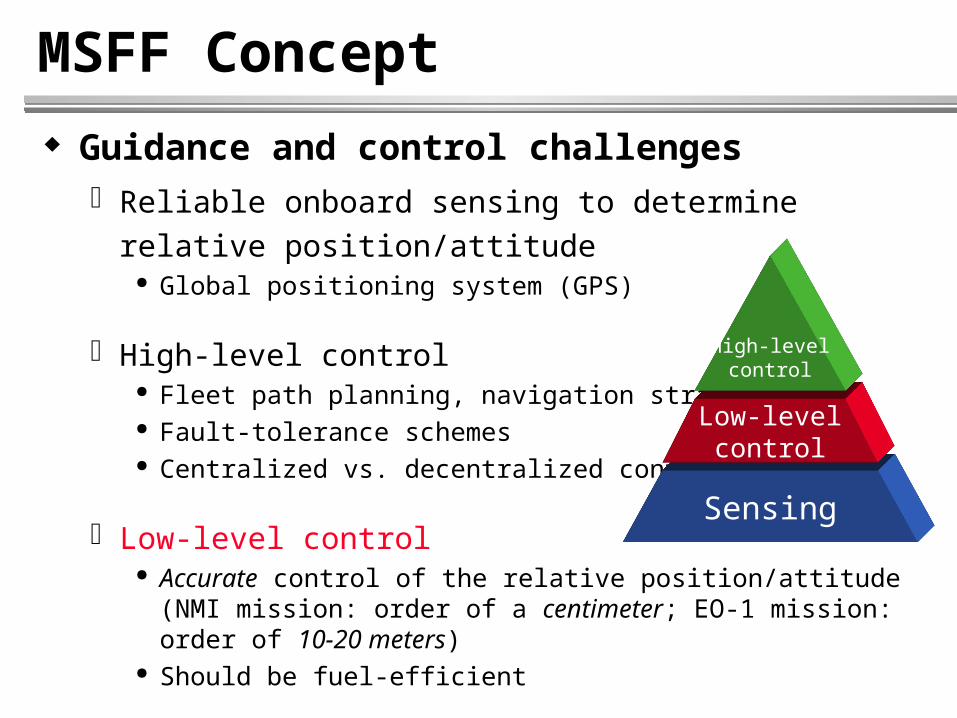
Guidance and control challenges Reliable onboard sensing to determine relative
position/attitude Global positioning system (GPS)
High-level control Fleet path planning, navigation strategy Fault-tolerance schemes Centralized vs. decentralized control
Low-level control Accurate control of the relative position/attitude (NMI mission:
order of a centimeter; EO-1 mission: order of 10-20 meters) Should be fuel-efficient
Sensing
Low-levelcontrol
High-levelcontrol
MSFF Concept
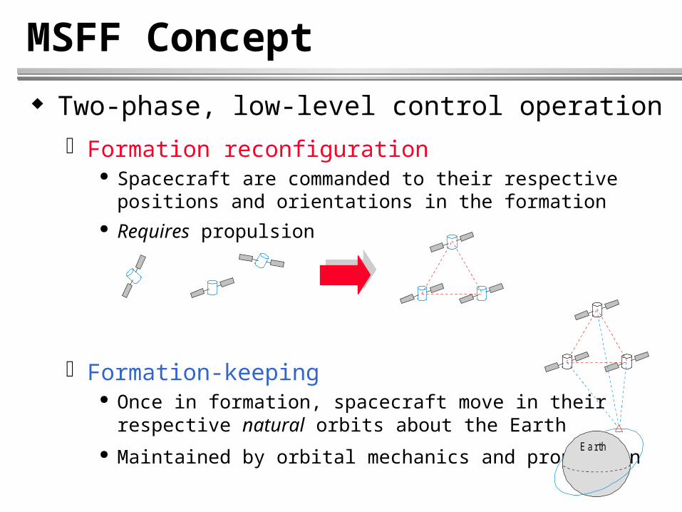
Two-phase, low-level control operation
Formation reconfiguration Spacecraft are commanded to their respective positions and
orientations in the formation Requires propulsion
Formation-keeping Once in formation, spacecraft move in their
respective natural orbits about the Earth
Maintained by orbital mechanics and propulsionEarth
Dynamic Model
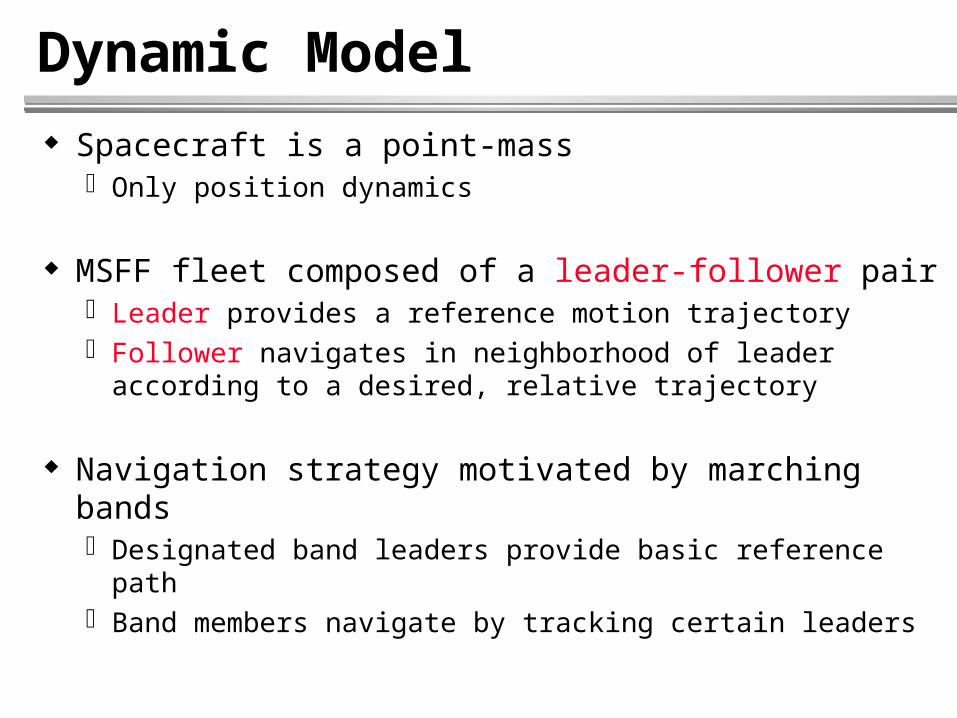
Spacecraft is a point-mass Only position dynamics
MSFF fleet composed of a leader-follower pair Leader provides a reference motion trajectory Follower navigates in neighborhood of leader according to
a desired, relative trajectory
Navigation strategy motivated by marching bands Designated band leaders provide basic reference path Band members navigate by tracking certain leaders

Dynamic Model
Schematic representation of the MSFF system
R(t): Position vector of leader from Earth center
(t): Position vector of follower relative to leader
Y
X
Z
Leader Spacecraft
Follow er Spacecraft
R
O
Earth
Inertia l CoordinateSystem

Dynamic Model
Newton’s law of gravitation
Two bodies attract each other with a force acting along the
line that joins them
G: Universal gravitational constant
r
r
r
mmGF
221
21
Y
X
Z
m 1
m 2
r
F 21
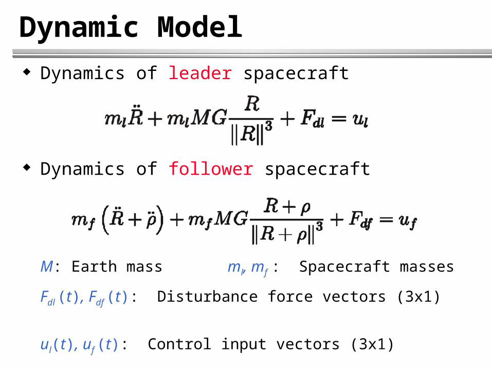
Dynamic Model Dynamics of leader spacecraft
Dynamics of follower spacecraft
M: Earth mass ml, mf : Spacecraft masses
Fdl (t), Fdf (t): Disturbance force vectors (3x1)
ul(t), uf (t): Control input vectors (3x1)
Dynamic Model
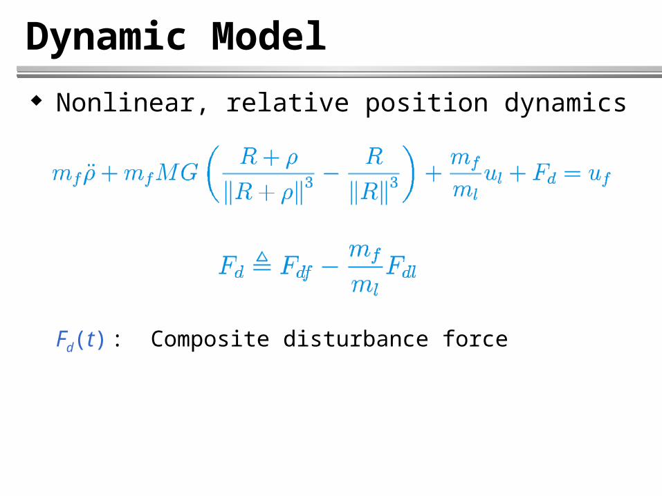
Nonlinear, relative position dynamics
Fd(t) : Composite disturbance force

Dynamic Model
Dynamics are given w.r.t. inertial coordinate frame
Spacecraft masses vary slowly in time due to fuel consumption and payload variations ml and mf are constant parameters
Disturbance forces result from solar radiation, aerodynamics, and magnetic field; hence, vary slowly in time Fd is a constant vector

Nonlinear Control
Common practice: Linearize relative position dynamics
Hill’s or Clohessy-Wiltshire equations
Design standard, linear controllers
Assumptions for all time
Leader in circular orbit around the Earth
Reasonable approach for formation-keeping
)()( tt R
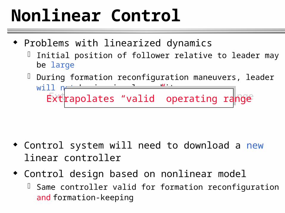
Nonlinear Control Problems with linearized dynamics
Initial position of follower relative to leader may be large
During formation reconfiguration maneuvers, leader will not be in circular orbit
Control system will need to download a new linear controller
Control design based on nonlinear model Same controller valid for formation reconfiguration and formation-
keeping
Extrapolates “valid” operating rangeExtrapolates “valid” operating range

Nonlinear Control
Significant contributions can be made to advance MSFF technology by exploiting nonlinear control
Several issues tailored for nonlinear control Dynamic model is nonlinear
Higher performance under broader operating conditions
Trajectory tracking problem Reconfiguration maneuvers, collision avoidance, minimize fuel
Uncertainties in system model Mass, inertia, disturbance, drag
Expensive sensor technology (GPS) may limit state info Actuator saturation
Physical limit or need to minimize fuel
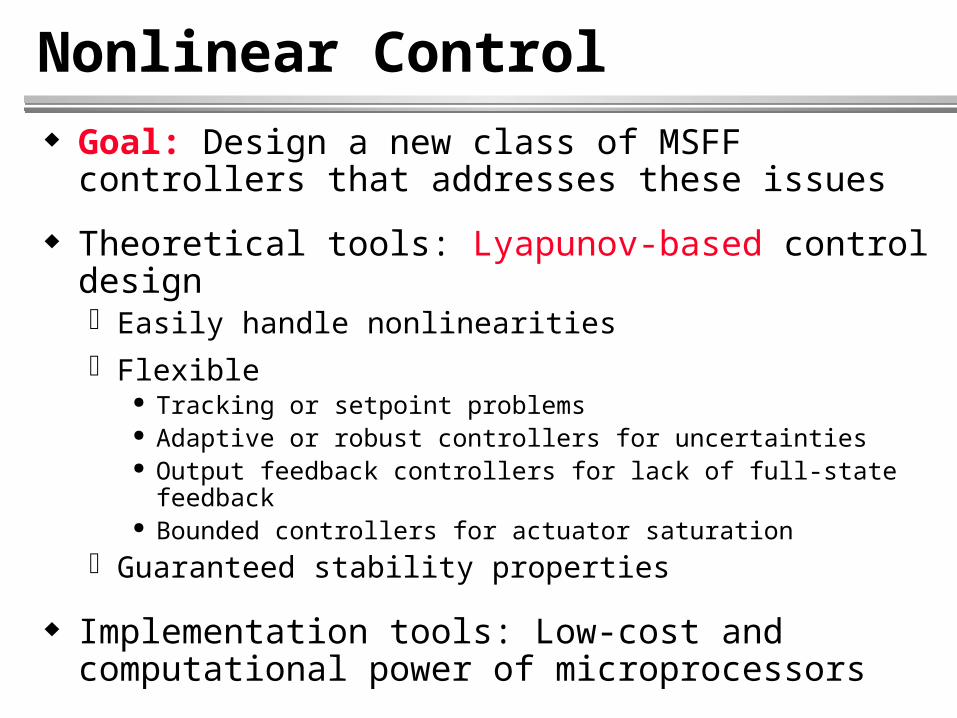
Nonlinear Control Goal: Design a new class of MSFF controllers that
addresses these issues
Theoretical tools: Lyapunov-based control design Easily handle nonlinearities
Flexible Tracking or setpoint problems Adaptive or robust controllers for uncertainties Output feedback controllers for lack of full-state feedback Bounded controllers for actuator saturation
Guaranteed stability properties
Implementation tools: Low-cost and computational power of microprocessors
Nonlinear Control (Design)
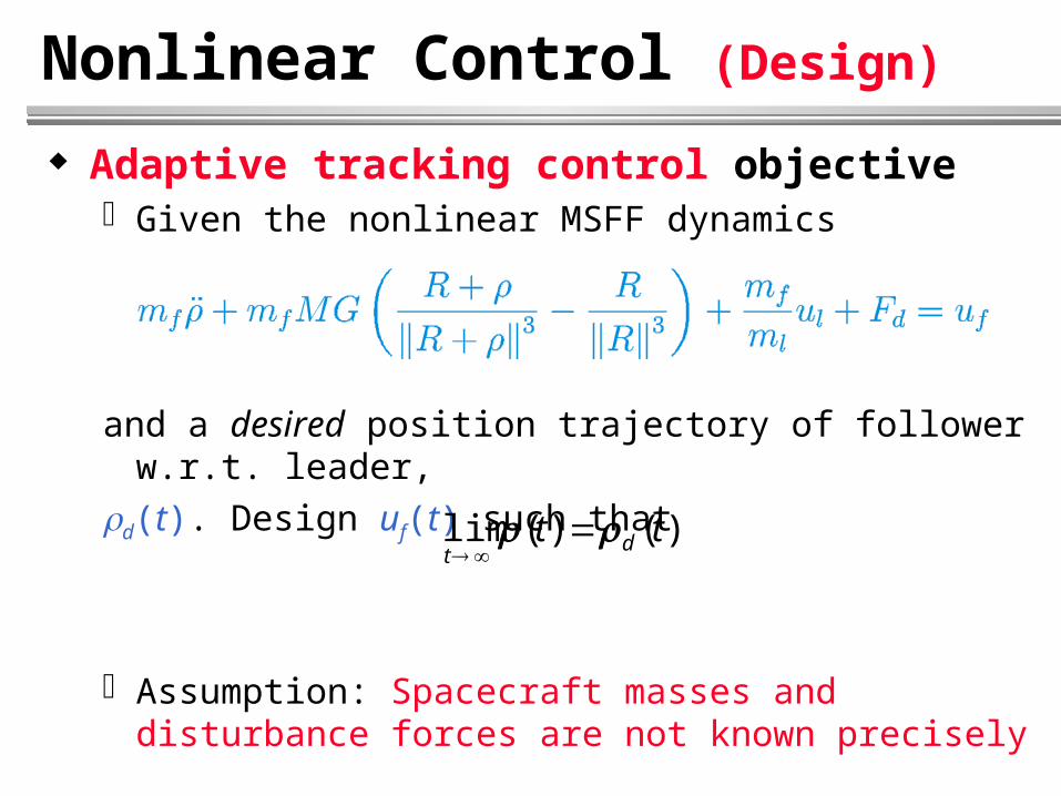
Adaptive tracking control objective Given the nonlinear MSFF dynamics
and a desired position trajectory of follower w.r.t. leader,
d(t). Design uf(t) such that
Assumption: Spacecraft masses and disturbance forces are not known precisely
)()(lim tt dt

Nonlinear Control (Design)
Property: Dynamics can be parameterized
Known matrix:
Unknown, constant parameter vector:
Nonlinear Control (Design)
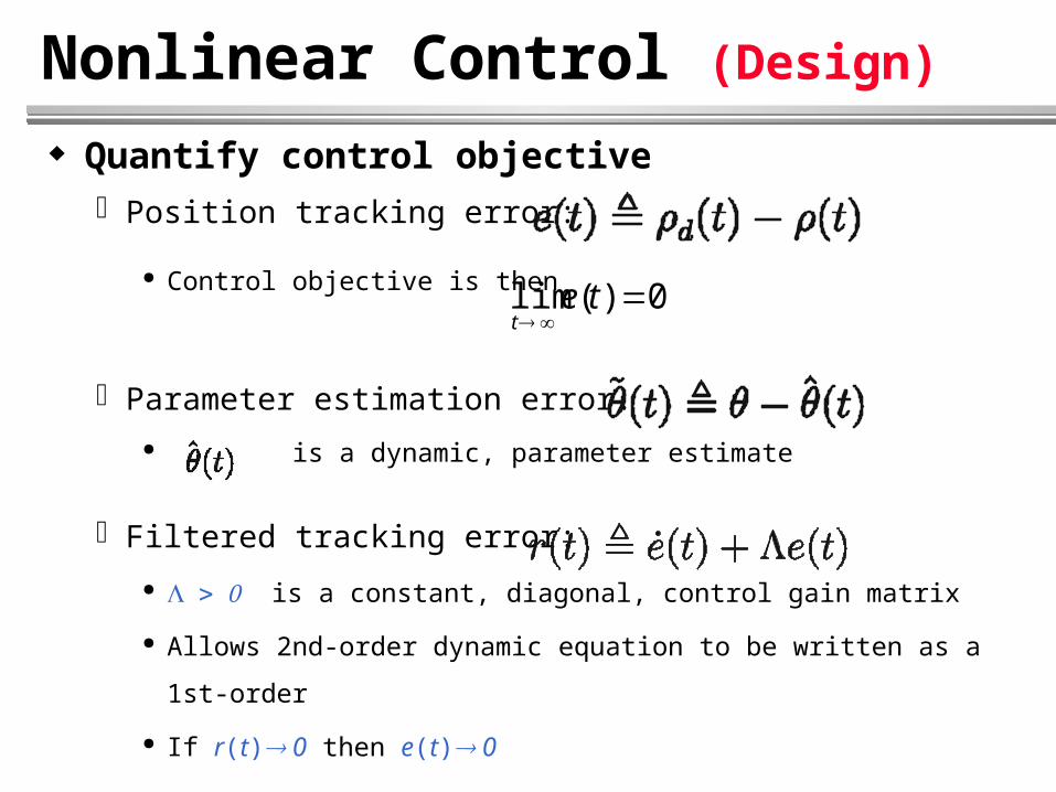
Quantify control objective Position tracking error:
Control objective is then
Parameter estimation error:
is a dynamic, parameter estimate
Filtered tracking error:
is a constant, diagonal, control gain matrix
Allows 2nd-order dynamic equation to be written as a 1st-order
If r(t) 0 then e(t) 0
0)(lim
tet
Nonlinear Control (Design)
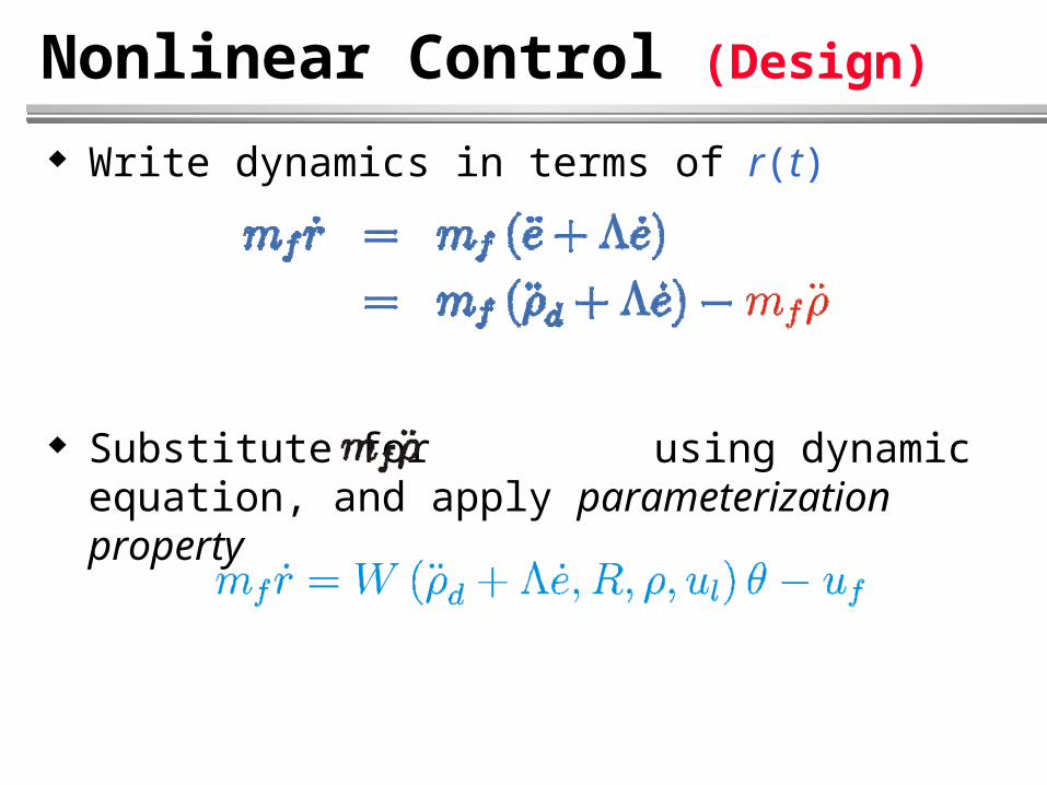
Write dynamics in terms of r(t)
Substitute for using dynamic equation, and apply parameterization property
Nonlinear Control (Design)
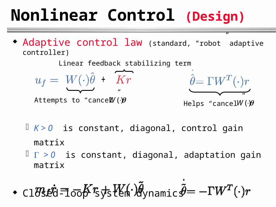
Adaptive control law (standard, “robot” adaptive controller)
K > 0 is constant, diagonal, control gain matrix > 0 is constant, diagonal, adaptation gain matrix
Closed-loop system dynamics
)(W
Linear feedback stabilizing term
Helps “cancel” )(WAttempts to “cancel”
+
Nonlinear Control (Stability Analysis)
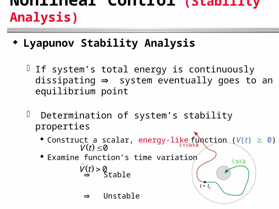
Lyapunov Stability Analysis
If system’s total energy is continuously dissipating system eventually goes to an equilibrium point
Determination of system’s stability properties Construct a scalar, energy-like function (V(t) 0)
Examine function’s time variation
Stable
Unstable
V t 0
V t 0
t t= 0
U nstab le
S tab le
Nonlinear Control (Stability Analysis)
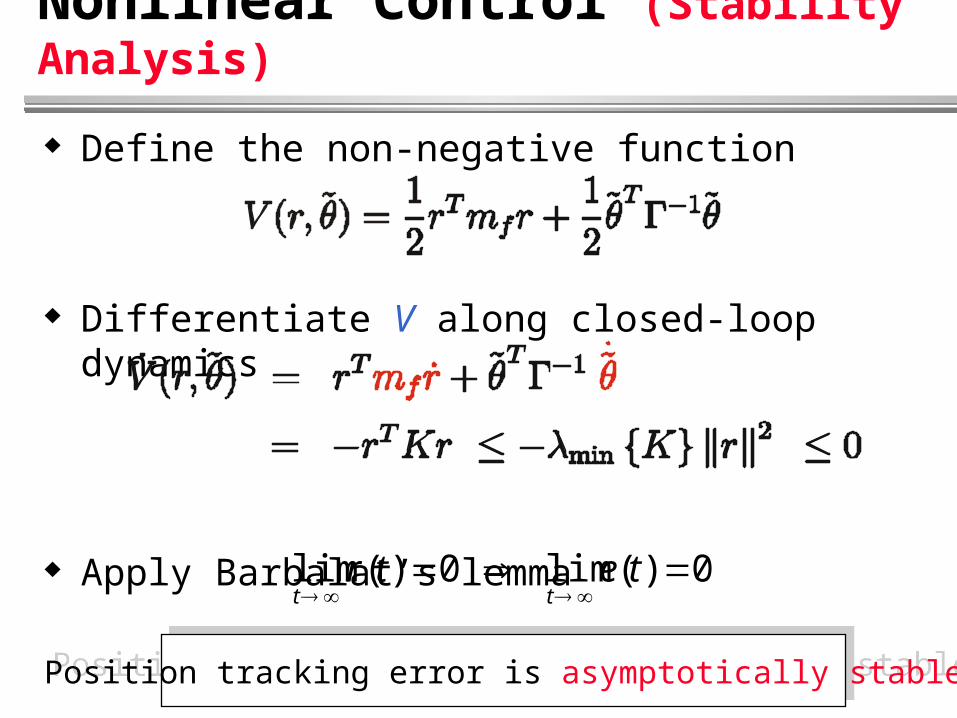
Define the non-negative function
Differentiate V along closed-loop dynamics
Apply Barbalat’s lemma0)(lim 0)(lim
tetr
tt
Position tracking error is asymptotically stablePosition tracking error is asymptotically stable
Simulation Results
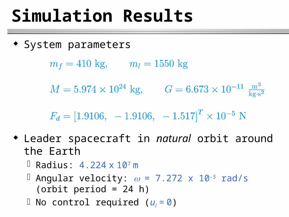
System parameters
Leader spacecraft in natural orbit around the Earth Radius: 4.224 x 10⁷ m Angular velocity: = 7.272 x 10⁻⁵ rad/s (orbit period = 24 h) No control required (ul = 0)
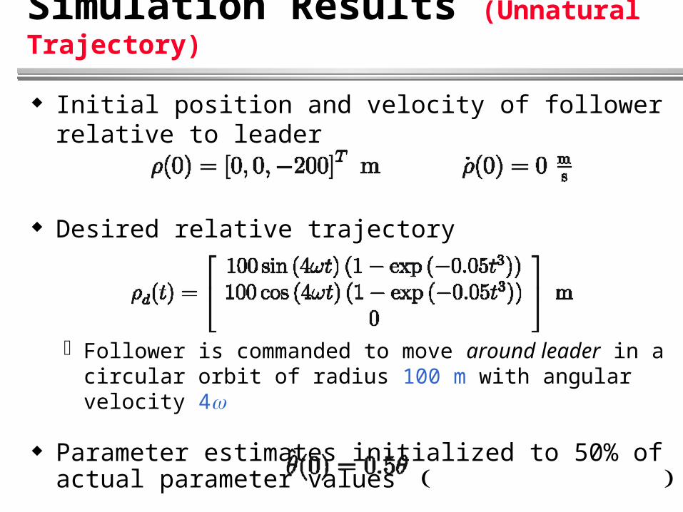
Simulation Results (Unnatural Trajectory)
Initial position and velocity of follower relative to leader
Desired relative trajectory
Follower is commanded to move around leader in a circular orbit of radius 100 m with angular velocity 4
Parameter estimates initialized to 50% of actual parameter values

Simulation Results (Unnatural Trajectory)
Relative Trajectory (‘*’ denotes leader spacecraft)
-100
-50
0
50
100
-150-100
-50
050
100150
-200
-150
-100
-50
0
50
100
x [m]
Relative Trajectory
y [m]
z [m
]
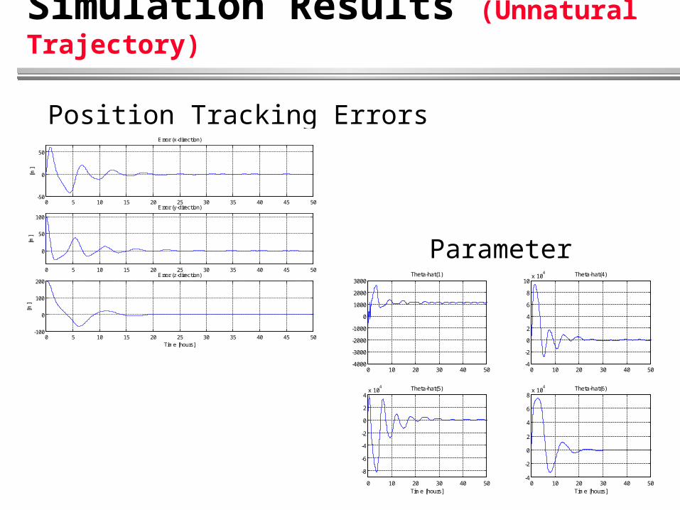
Simulation Results (Unnatural Trajectory)
Position Tracking Errors
Parameter Estimates
0 5 10 15 20 25 30 35 40 45 50-50
0
50
[m]
Error (x-direction)
0 5 10 15 20 25 30 35 40 45 50
0
50
100
[m]
Error (y-direction)
0 5 10 15 20 25 30 35 40 45 50-100
0
100
200
Time [hours]
[m]
Error (z-direction)
0 10 20 30 40 50-4000
-3000
-2000
-1000
0
1000
2000
3000Theta-hat(1)
0 10 20 30 40 50-4
-2
0
2
4
6
8
10x 10
4 Theta-hat(4)
0 10 20 30 40 50
-8
-6
-4
-2
0
2
4x 10
4
Time [hours]
Theta-hat(5)
0 10 20 30 40 50-4
-2
0
2
4
6
8x 10
4
Time [hours]
Theta-hat(6)

Simulation Results (Unnatural Trajectory)
Control Forces
Maximum magnitude = 0.02 N
0 5 10 15 20 25 30 35 40 45 50
-0.02
0
0.02
[N]
Control Force (x-direction)
0 5 10 15 20 25 30 35 40 45 50
-0.02
0
0.02
[N]
Control Force (y-direction)
0 5 10 15 20 25 30 35 40 45 50
-5
0
5
x 10-3
Time [hours]
[N]
Control Force (z-direction)

Simulation Results (Natural Trajectory)
Follower commanded to move in natural, elliptical orbit around the Earth with orbit period = 24 h Typical of formation-keeping
Elliptical orbit for d(t)obtained by integrating
Relative dynamics with ul = uf = 0 and Fd = 0
Proper initial conditions must be selected
Parameter estimates initialized to zero
0)0( ̂
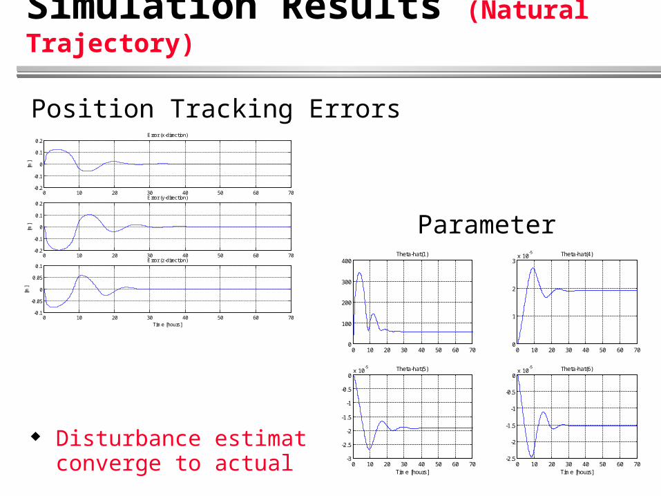
Simulation Results (Natural Trajectory)
Position Tracking Errors
Parameter Estimates
Disturbance estimatesconverge to actual values
0 10 20 30 40 50 60 70-0.2
-0.1
0
0.1
0.2
[m]
Error (x-direction)
0 10 20 30 40 50 60 70-0.2
-0.1
0
0.1
0.2
[m]
Error (y-direction)
0 10 20 30 40 50 60 70-0.1
-0.05
0
0.05
0.1
Time [hours]
[m]
Error (z-direction)
0 10 20 30 40 50 60 700
100
200
300
400Theta-hat(1)
0 10 20 30 40 50 60 700
1
2
3x 10
-5 Theta-hat(4)
0 10 20 30 40 50 60 70-3
-2.5
-2
-1.5
-1
-0.5
0x 10
-5 Theta-hat(5)
Time [hours]0 10 20 30 40 50 60 70
-2.5
-2
-1.5
-1
-0.5
0x 10
-5 Theta-hat(6)
Time [hours]
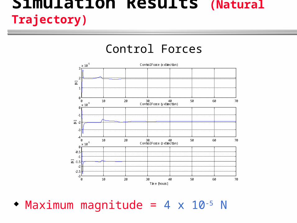
Simulation Results (Natural Trajectory)
Control Forces
Maximum magnitude = 4 x 10⁻⁵ N
0 10 20 30 40 50 60 700
1
2
3x 10
-5
[N]
Control Force (x-direction)
0 10 20 30 40 50 60 70-4
-3
-2
-1
0x 10
-5
[N]
Control Force (y-direction)
0 10 20 30 40 50 60 70-3
-2.5
-2
-1.5
-1
-0.5
0x 10
-5
Time [hours]
[N]
Control Force (z-direction)
Fuel Consumption Issue
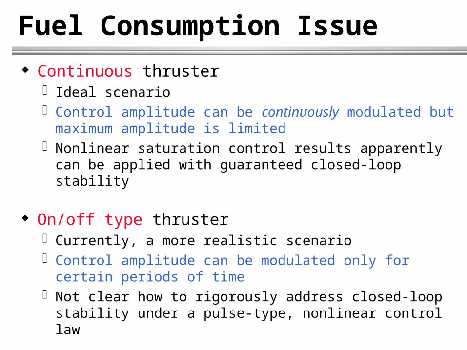
Continuous thruster Ideal scenario Control amplitude can be continuously modulated but
maximum amplitude is limited Nonlinear saturation control results apparently can be
applied with guaranteed closed-loop stability
On/off type thruster Currently, a more realistic scenario Control amplitude can be modulated only for certain
periods of time Not clear how to rigorously address closed-loop stability
under a pulse-type, nonlinear control law

Fuel Consumption Issue
Formation-keeping On/off thrusters may suffice When “off”, orbital mechanics maintain natural orbit
Formation reconfiguration Demanding maneuvers will require significant control
effort When on/off thrusters are used, obvious trade-off between
performance and fuel consumption Reconfiguration may last for only short periods of time
Fuel Consumption Issue
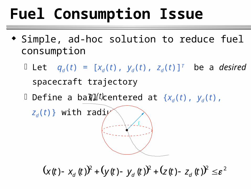
Simple, ad-hoc solution to reduce fuel consumption
Let qd(t) = [xd(t), yd(t), zd(t)]T be a desired spacecraft
trajectory
Define a ball centered at {xd(t), yd(t), zd(t)} with radius
2222 )()()()()()( tztztytytxtx ddd
q (t)d
Fuel Consumption Issue
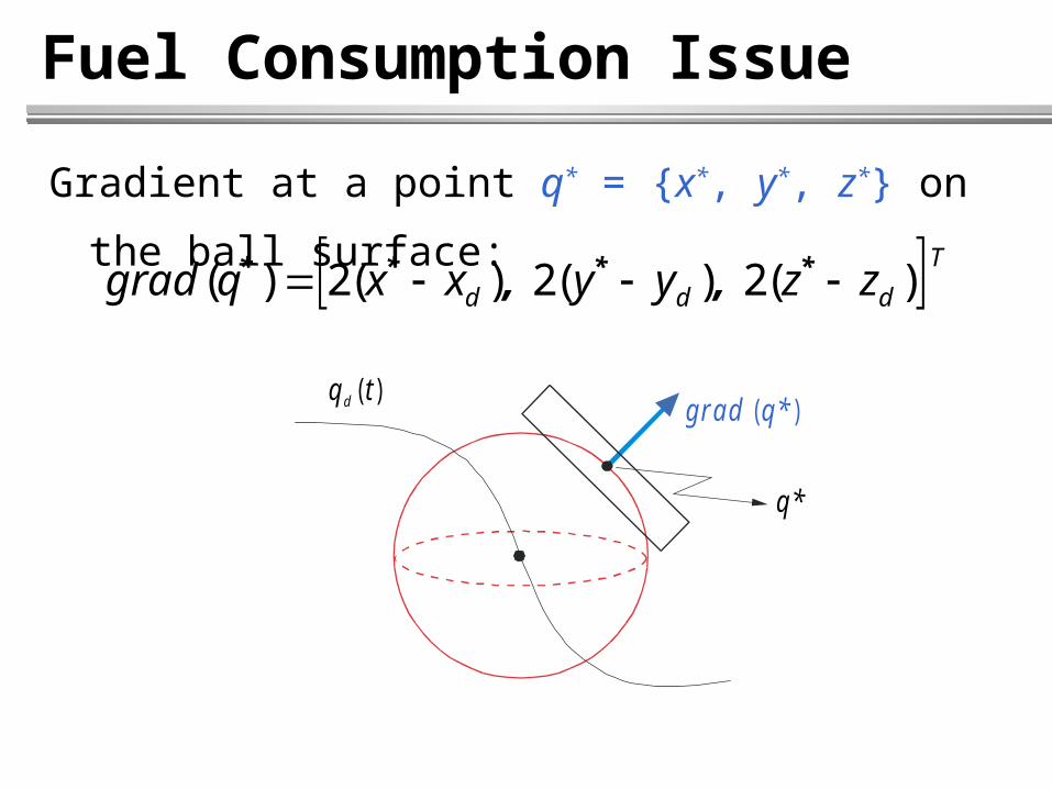
Gradient at a point q* = {x*, y*, z*} on the ball surface:
T
ddd zzyyxxqgrad
)(2 )(2 )(2)( **** ,,
q ( t)d
q *
g ra d q *( )

Fuel Consumption Issue
On/Off Type Control Algorithm
Goal: Control spacecraft position such that it never leaves the ball
qs(t) = [xs(t), ys(t), zs(t)]T: spacecraft position
1. If
2. If
2222s dsdsd zzyyxx Control offControl off
2222s dsdsd zzyyxx Control onControl on

Fuel Consumption Issue
On/Off Type Control Algorithm (cont.)
3. If
If
Else
2222s dsdsd zzyyxx
0 ss qgradq Control offControl off
g ra d q( )s
q s
.
90
Control onControl ong rad q( )s
q s
.90
Fuel Consumption Issue
Control on means: Control is set to the designed nonlinear control Left on for some finite time interval T Algorithm is resumed only after T has expired
Case 2 (spacecraft outside ball) may occur during initialization of formation reconfiguration
Trade-off between tracking performance and fuel consumption Asymptotic tracking vs. bounded tracking with less fuel

Ongoing and Future Research Account for spacecraft attitude dynamics
MSFF position/attitude tracking controller 4-parameter kinematic representation (quaternions)
Account for higher-order gravitational perturbations (J2 effect) and atmospheric drag
Output feedback controller Only GPS position measurements No GPS “estimation” architecture for velocity
Formation control of autonomous vehicles Aircraft, ships, underwater vehicles, mobile robots

Ongoing and Future Research
Testbed for preliminary experiments
3 DOF DC motor-propeller pairs provide actuation Optical encoders sense the 3 angular positions
Yaw
Roll
P itch
DC Motor
Propeller
Base
Leader"Spacecraft"
Follower"Spacecraft"