Embed Size (px)
Citation preview

Hindawi Publishing CorporationMathematical Problems in EngineeringVolume 2013 Article ID 745912 10 pageshttpdxdoiorg1011552013745912
Research ArticleUnbalanced Magnetic Pull Effect on Stiffness Models ofActive Magnetic Bearing due to Rotor Eccentricity in BrushlessDC Motor Using Finite Element Method
Bangcheng Han12 Shiqiang Zheng12 and Xiquan Liu1
1 School of Instrument Science and Optoelectronics Engineering Beihang University Beijing 100191 China2 Science and Technology on Inertial Laboratory Beijing 100191 China
Correspondence should be addressed to Shiqiang Zheng zhengshiqiangbuaaeducn
Received 24 February 2013 Revised 6 June 2013 Accepted 13 June 2013
Academic Editor Sarp Adali
Copyright copy 2013 Bangcheng Han et alThis is an open access article distributed under the Creative CommonsAttribution Licensewhich permits unrestricted use distribution and reproduction in any medium provided the original work is properly cited
We firstly report on an investigation into the unbalanced magnetic pull (UMP) effect on the static stiffness models of radial activemagnetic bearing (RAMB) in brushless DC motor (BDCM) in no-loaded and loaded conditions using the finite element method(FEM) The influences of the UMP on the force-control current force-position current stiffness and position stiffness of RAMBare clarified in BDCM with 100 kW rated power We found the position stiffness to be more susceptible to UMP The primarysource of UMP is the permanent magnets of BDCM In addition the performance of RAMB is affected by the UMP ripples duringmotor commutation and also periodically affected by the angular position of rotorThe characteristic curves of RAMB force versuscontrol current (or rotor position) and angular position of rotor affected by the UMP are givenThemethod is useful in design andoptimization of RAMB in magnetically suspended BDCMs
1 Introduction
The number of commercialindustrial applications for mag-netic bearings is large and still growing because of the uniqueadvantages oil-free operation vibration control and on-linemonitoring Nowadays magnetic bearings have been widelyused in refrigeration compressors [1] turbo expandersblower industry (specifically in the wastewater treatmentarea) pumps and high-speed machines [2ndash5]These systemsare composed with magnetic bearings (MBs) and motor andthe different components are assembled on the rotor shaftwhich is supported by the MBs The rotor supported by theMBs would be naturally combined by the mechanical modelDue to manufacturing imperfectness of mechanical partsandor the use of magnetic bearings in high-speed motorsthe rotor eccentricity is inevitable The magnetic field inmotors will create tangential electromagnetic forces on therotor which will produce torque The radial forces namedas unbalanced magnetic pull (UMP) [6] are generated atthe same time in which case the UMP is developed and ininteraction with the rotor supported by magnetic bearings
and they may cause significant effects on the static mathe-matical model of magnetic bearings An analytical model foranalyzing permanent magnet (PM) motors is presented forpredicting of magnetic field and magnetic forces includingUMP [7] A simple analytical model which is able to accountfor the damping effects of a cage rotor on the UMP whenthe rotor is dynamically eccentric is presented [8]The UMPswhich act upon the rotor of a salient-pole synchronousgenerator due to the eccentric motion of the rotor shaftin the presence of magnetic field in no-loaded and loadedconditions are calculated using the finite elementmethod [9]Dynamic eccentricity up to 80 is put into the model of alarge brushless rare-earth permanent magnet motors modeland a variety of simulations carried out to investigate theUMP [10] A general analytical model is developed to predictthe UMP which results in permanent-magnet brushless acand dc machines having a diametrically asymmetric disposi-tion of slots and phase windings [11] An investigation on theUMP in ferrite-magnet fractional-slot brushless permanent-magnet motors due to either magnetic asymmetry or staticrotor eccentricity is reported [12] An analytic model for
2 Mathematical Problems in Engineering
5
3
34
2
2
61
fy119860
yA ym
yB
fy119861zA
zmzB
fUMP
Tfx119860
fx119861
xA
xmxB
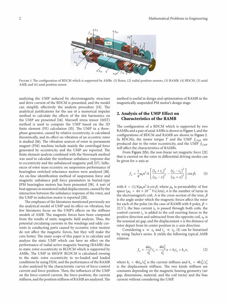
Figure 1 The configuration of BDCM which is supported by AMBs (1) Rotor (2) radial position sensors (3) RAMB (4) BDCM (5) axialAMB and (6) axial position sensor
analyzing the UMP induced by electromagnetic structureand drive current of the BDCM is presented and the modelcan simplify effectively the analysis procedure [13] Theanalytical justifications for the use of a numerical impulsemethod to calculate the effects of the slot harmonics onthe UMP are presented [14] Maxwell stress tensor (MST)method is used to compute the UMP based on the 2Dfinite element (FE) calculation [15] The UMP in a three-phase generator caused by relative eccentricity is calculatedtheoretically and its effect on vibration of an eccentric rotoris studied [16] The vibration sources of rotor in permanentmagnet (PM) machine include mainly the centrifugal forcegenerated by eccentricity and the UMP are reported Thefinite element analysis combined with the Newmark methodwas used to calculate the nonlinear unbalance response dueto eccentricity and the unbalanced magnetic pull [17] Influ-ences of rotor mass eccentric on suspension performance ofbearingless switched reluctance motors were analyzed [18]An on-line identification method of suspension force andmagnetic unbalance pull force parameters in buried-typeIPM bearingless motors has been presented [19] A sort ofbeat appears inmonitored radial displacements caused by theinteraction between the unbalance response of the rotor andthe UMP in induction motor is reported [20]
The emphases of the literatures mentioned previously arethe analytical model of UMP and its effect on vibration butfew literatures focus on the UMPrsquos effects on the stiffnessmodels of AMB The magnetic forces have been computedfrom the results of static magnetic field analysis Thus thepotential circulating currents in the windings and eddy cur-rents in conducting parts caused by eccentric rotor motiondo not affect the magnetic forces but they will make thecore hotter The main scope of this paper is to calculate andanalyze the static UMP which can have an effect on theperformance of radial active magnetic bearing (RAMB) dueto static rotor eccentricity in BLDCM which is supported byAMBs The UMP in 100 kW BLDCM is calculated owningto the static rotor eccentricity in no-loaded and loadedconditions by using FEM and the performance of the RAMBis also analyzed by the characteristic curves of force-controlcurrent and force-position Then the influences of the UMPon the force-control current the force-position the currentstiffness and the position stiffness of RAMBare analyzedThe
method is useful in design and optimization of RAMB in themagnetically suspended PMmotorrsquos design stage
2 Analysis of the UMP Effect onCharacteristics of the RAMB
The configuration of a BDCM which is supported by twoRAMBs and a pair of axial AMBs is shown in Figure 1 and theconfigurations of BDCM and RAMB are shown in Figure 2In BDCMs the motor torque 119879 and the UMP 119891UMP areproduced due to the rotor eccentricity and the UMP 119891UMPwill affect the characteristics of RAMBs
From Figure 2(b) the non-linear net magnetic force [21]that is exerted on the rotor in differential driving modes canbe given for 119909-axis as
119891119909=1
412058301198992
119860[(1198940+ 119894119909)2
(1199040minus 119909)2minus(1198940minus 119894119909)2
(1199040+ 119909)2] cos120573 (1)
with 119896 = (14)12058301198992
119860 cos120573 where 1205830is permeability of free
space (1205830= 4120587 times 10
minus7 VsAm) 119899 is the number of turns inthe electromagnetrsquos coil 119860 is the cross-section of the iron 120573is the angle under which the magnetic forces affect the rotorfor each of the poles (in the case of RAMB with 8 poles 120573 =225∘) the bias current 119894
0is passed through both coils the
control current 119894119909is added to the coil exerting forces in the
positive direction and subtracted from the opposite coil 1199040is
the nominal air gap and the displacement 119909 is the distance ofrotor depart from its center position in 119909-axis direction
Considering 119909 ≪ 1199040and 119894119909≪ 1198940 (1) can be linearized
by using Taylorrsquos series It yields the following typical AMBrelation
119891119909=41198961198940
1199042
0
119894119909+41198961198942
0
1199043
0
119909 = 119896119894119894119909+ 119896119904119909 (2)
where 119896119894= 4119896119894
01199042
0is the current stiffness and 119896
119904= 4119896119894
2
01199043
0
is the displacement stiffness The two kinds stiffness areconstants depending on the magnetic bearing geometry (airgap dimensions material and the coil turns) and the biascurrent without considering the UMP
Mathematical Problems in Engineering 3
Permanent magnet
Stator coreWinding
Slot for armature winding
Rotor core
N
NS
S
Air gap
y
120572
fUMP
x
(a)
Rotor core Stator core
Winding Air gapy
x
120573
(b)
Figure 2 The configurations of the BDCM and the RAMB (a) The configuration of BDCM (b) The configuration of RAMB
2
15
1
05
0
B(T
)
0 1000 2000 3000 4000 5000 6000 7000H (Am)
Figure 3 B-H curve for the ferromagnetic material
The UMP will have an effect on the net magnetic force ofRAMB in BDCM and the net magnetic force discussed in (1)is rewritten as
1198911015840
119909=1
412058301198992
119860[(1198940+ 119894119909)2
(1199040minus 119909)2minus(1198940minus 119894119909)2
(1199040+ 119909)2] cos120573 + 119891UMP cos
120572
2
(3)
where 120572 is the angle between the vector of the UMP 119891UMPand the 119909-axis From (3) the net magnetic force the currentstiffness and the displacement stiffness are affected by theUMPThere are two RAMBs in the system shown in Figure 1and thereby the UMP is divided by 2
3 Finite Element Model for Calculation ofthe UMP Effect on RAMB
The eccentric motion of the rotor supported by AMBs in no-loaded or loaded operation will result in the UMP which actsupon the rotor and consequently on the magnetic bearingsof the BDCM In this paper the goal is to use the FEM to
Table 1 Designed parameters of the BDCM
Parameters ValueWeight of the rotor (kg) 236Number of pole pairs 2Rated power (kW) 100Rated voltage (V) 480Maximum speed (rmin) 32000Number of stator slots 24Connection StarWinding arrangement (series) Double layerParallel branches of the stator winding 4Rotor outer diameter (mm) 89Air gap length (mm) 4Stator inner diameter (mm) 97Axial length (mm) 150
Table 2 Designed parameters of the RAMB
Parameters ValueStator outer diameter (mm) 228Stator inner diameter (mm) 898Air gap length (mm) 04Rotor outer diameter (mm) 89Rotor inner diameter (mm) 60Number of turns 160Bias current (A) 1Axial length (mm) 16
simulate the UMP and calculate the results of the UMP effecton the characteristics of RAMB in BDCM
An example of magnetically suspended BDCM is givenand the design parameters of the BDCM and the RAMB areshown in Tables 1 and 2 respectively The example is usedto clarify the UMP effect on the characteristics of RAMBin magnetically suspended BDCM for no-loaded and loadedconditions and so forth
4 Mathematical Problems in Engineering
(a) (b)
Figure 4 The 2-dimentional FE mesh model of BDCM and RAMB except the air (a) The 2-dimentional FE mesh model of BDCM exceptthe air (b) The FE mesh model of RAMB except the air
Table 3 UMP calculation at different loads
Item Stator current (A)Without stator current in BDCM 0No load in BDCM 32Rated load in BDCM 208
4 Simulation Results and Discussion
41 The Load Currents in BDCM and Finite Element ModelThe FEM simulations used to calculate the UMPrsquos effects oncharacteristics of RAMB resulting from the eccentric of rotorfor no-loaded and loaded conditions have been carried outin this section As shown in Table 3 the UMP calculations atdifferent loads are conducted in the following three cases
(a) The UMP calculation without stator current which isused to clarify the UMP produced by the permanentmagnet in BDCM effect on the characteristics
(b) The UMP calculation for no-loaded condition whichis used to clarify theUMPproduced by the permanentmagnet and no-loaded condition in BDCM effect onthe characteristics
(c) The UMP calculation for loaded condition which isused to clarify the UMP produced by the permanentmagnet and rated loaded condition in BDCM effecton the characteristics
The 2-dimensional (2D) finite element (FE) models ofBDCM and RAMB are established and are shown in Figure 2except the air The B-H curve of ferromagnetic materialwhich is used for motor stator RAMBrsquos stator and RAMBrsquosrotor is shown in Figure 3 when the nonlinear analysisis considered The software of Ansoft Maxwell is used tocalculate electromagnetic field The 2D FE mesh model ofBDCM is shown in Figure 4(a) the air is not shown to givea better view of model and there are 42748 elements totallyThe FEmeshmodel of RAMB is shown in Figure 4(b) the airis also not shown and there are 25942 elements in total Thevector potential boundary is available for use in Maxwell 2D
The lines of magnetic flux for BDCM in loaded conditionare shown in Figure 5(a)The lines ofmagnetic flux forRAMBwith bias current are shown in Figure 5(b)
42 The Static Linearized Model of the RAMB and the UMPProduced by Permanent Magnet in BDCM In the rotorcenter the linearized model of RAMB without consideringUMP through the 2D FEM is given in (4) The currentstiffness 119896
119894= 2972NA and the position stiffness 119896
119904=
minus772020Nm
119891119909= 119896119894119894119909+ 119896119904119909 = 2972119894
119909minus 772020119909 (4)
The UMP is produced by the permanent magnet inBDCM without stator current The following analysis con-siders the eccentricity and angular position of rotor Theeccentricity changes from minus200120583m to 200120583m and the angu-lar position of motor rotor changes from 0∘ to 180∘ Thecharacteristic curves of UMP-eccentricity-angular positionof rotor are shown in Figure 6 The UMP is only calculatedin 119909-axis as shown in Figure 2(a) It is obvious that thecharacteristic curves are linear the UMP is determined bythe eccentricity and is independent of the angular of motorrotor The UMP is 387N with the eccentricity of minus200120583mThe relationship between the UMP and the eccentricity canbe given as follows
119891UMP = 119896119890119901119890119909 = minus193220119890119909 (5)
where 119896119890119901
is the slope of 119891UMP versus the eccentricity andthe 119890119909is the eccentricity This is a disadvantage because
the additional magnetic bearing force (MBF) is necessaryto overcome the negative slope coefficient limiting theachievable control performance
43 The Characteristic Curves of the MBF Affected by theUMP of BDCM with No-Loaded Condition The relationshipbetween the MBF of RAMB and the control current iscalculated by FEM and is shown in Figure 7 The charac-teristic curves of MBF versus the control current which is
Mathematical Problems in Engineering 5
(a) (b)
Figure 5 The lines of magnetic flux for the BDCM and the RAMB (a) The lines of magnetic flux for BDCM in loaded condition (b) Thelines of magnetic flux for RAMB with bias current
40
30
20
10
0
minus10
minus20
minus30
minus40
UM
P (N
)
180150 120 90 60 30 0
Angular position of rotor (deg)
minus200minus1000
100200 Eccentricity (120583m)
Figure 6 The UMP produced by permanent magnet in BDCMversus eccentricity and angular position of motor rotor
affected by the UMP produced by the permanent magnetin BDCM for the different values of eccentricity are alsoshown in Figure 7 The current stiffness curves of RAMBare shown in Figure 8 and these 5 curves are coincidentIt is obvious that the UMP only changes the amplitude ofMBF without changing its current stiffness and the linearrelationship between the MBF and the control current Theadditional MBF produced by control current is necessaryto overcome the UMP For example the 387N provided byRAMB is necessary to overcome theUMPwith eccentricity ofminus200120583m The mathematic model of the MBF versus controlcurrent affected by the UMP can be given as follows
119891119894= 119896119894119894119909+ 119896119890119901119890119909asymp 2972119894
119909minus 193220119890
119909 (6)
It is different from the characteristic curves ofMBF versuscontrol current affected by the UMP the UMP affects theamplitude and linear relationship between the MBF versusrotor position of the RAMB as the characteristic curves
350300250200150100
500
minus50
minus100
minus150
minus200
minus250
minus300
minus350
Forc
e (N
)
minus1 minus05 0 05 1Control current (A)
minus387N
minus193N
No UMPEccentricity minus200120583mEccentricity minus100120583m
Eccentricity 200 120583mEccentricity 100 120583m
Figure 7 The characteristic curves of the MBF versus controlcurrent affected by theUMPwhich is produced by the PM inBDCM
are shown in Figure 9 The UMP changes the equilibriumposition of the RAMB the additional control current ofRAMB is necessary to maintain system stabilityThe positionstiffness of RAMB is also varied by the UMP and is shownin Figure 10 The absolute value of position stiffness in rotorcenter position increases from 772020Nm (No UMP) to960346Nm (affected by UMP) namely increases by 244The position stiffness when UMP is not generated is differentfrom those when the rotor is eccentric The reason is thereis no UMP when the rotor located its center and only thetorque is generated by the BDCM but the UMP will begenerated by the PM and (or) the control current in BDCMdue to the rotor eccentric then the characteristic curves ofthe MBF will be modified by the UMP Thus the positionstiffness model is modified The rate of the change of theUMP produced by BDCM versus the rotor eccentricity is the
6 Mathematical Problems in Engineering
297
294
291
288
285
282
279
276
273
270
Curr
ent s
tiffne
ss (N
A)
minus1 minus05 0 05 1Control current (A)
No UMPEccentricity minus200120583mEccentricity minus100120583m
Eccentricity 200 120583mEccentricity 100 120583m
2972 NA
Figure 8 The characteristic curves of the current stiffness affectedby the UMP which is produced by the PM in BDCM
300250200150100
500
minus50
minus100
minus150
minus200
minus250
minus300
Forc
e (N
)
minus200 minus150 minus100 minus50 0 50 100 150 200Rotor position (120583m)
No UMPEccentricity minus200120583mEccentricity minus100120583m
Eccentricity 200 120583mEccentricity 100 120583m
minus193Nminus387N
Figure 9The characteristic curves of theMBF versus rotor positionaffected by the UMP of BDCM with no-loaded condition
same so it is equal between the eccentricities of 100 120583m and200120583mThe position stiffness affected by the different valuesof eccentricity is the same and their curves are coincidentThe mathematic model of the MBF versus rotor positionaffected by the UMP can be given as follows
119891119904= 119896119904119901119909 + 119896119890119901119890119909asymp minus960346119909 minus 193220119890
119909 (7)
Equations (6) and (7) are substituted into (3) consideringthe effect of the UMP produced by permanent magnet inBDCM in 119909-axis which gives
1198911015840
119909= 119896119894119894119909+ 119896119904119901119909 + 2119896
119890119901119890119909cos 0∘
= 2972119894119909minus 960346119909 minus 386440119890
119909
(8)
minus075
minus09
minus105
minus12
minus135
minus15
minus165
minus18
minus195
minus21
Posit
ion
stiffn
ess (
N120583
m)
minus200 minus150 minus100 minus50 0 50 100 150 200Rotor position of RAMB (120583m)
No UMPEccentricity minus200120583mEccentricity minus100120583m
Eccentricity 200 120583mEccentricity 100 120583m
minus772020Nm
minus960346Nm
Figure 10The characteristic curves of the position stiffness affectedby the UMP of BDCM with no-loaded condition
40
30
20
10
0
minus10
minus20
minus30
minus40
UM
P (N
)
180150 120 90 60 30
0
Angular position of rotor (deg)
minus200minus100
0100
200 Eccentricity (120583m)
Figure 11 The UMP in no-loaded condition versus rotor eccentric-ity and angular position of motor rotor
The UMP is produced by the permanent magnet andstator current (32 A) in BDCM for no-loaded opera-tion The following analysis considers the eccentricity andangular position of rotor The eccentricity changes fromminus200120583m to 200120583m and the angular position of motorrotor changes from 0∘ to 180∘ The characteristic curves ofUMP-eccentricity-angular position of rotor are shown inFigure 11 The UMP is also calculated in 119909-axis as shown inFigure 2(a) It is obvious that the characteristic curves in no-loaded condition are the same as the UMP produced by thepermanent magnet in BDCM The UMP produced by thestator current in no-loaded condition is very small and canbe neglected for the large air gap
Mathematical Problems in Engineering 7
40
30
20
10
0
minus10
minus20
minus30
minus40
UM
P (N
)
minus200 minus150 minus100 minus50 0 50 100 150 200
41
40
39
38
37
36
35minus200 minus195 minus190 minus185 minus180 minus175 minus170
0∘
10∘20∘
30∘
Enlarged
Eccentricity (120583m)
(a)
40302010
0minus10
minus20
minus30
minus40
UM
P (N
)
180150120 90 60 30 0
Angular position of rotor (deg)200 100
0 minus100minus200
Eccentricity (120583m)
(b)
Figure 12 The UMP in loaded condition (stator current 208A) versus eccentricity and angular position of motor rotor (a) 2D (b) 3D
320
240
160
80
0
minus80
minus160
minus240
minus320
Forc
e (N
)
minus1 minus08 minus06 minus04 minus02 0 02 04 06 08 1Control current (A)
No UMPEccentricity minus200120583mEccentricity minus100120583m
Eccentricity 200 120583mEccentricity 100 120583m
409 N
203 N
Figure 13 The characteristic curves of the MBF versus controlcurrent affected by the UMP for loaded operation in BDCM
44The Characteristic Curves of theMBFAffected by the UMPof BDCM in Loaded Condition The previous analysis showsthat the UMP for no-loaded condition or without statorcurrent in BDCM is determined by the value of eccentricityand is independent of the angular of motor rotor but theUMP for loaded (stator current 208A) condition is notonly affected by the eccentricity but also affected by theangular position of motor rotor with the larger value ofeccentricity The characteristic curves of the UMP in loadedcondition versus eccentricity and angular position of motorrotor are shown in Figure 12 For example the value of UMPwill change from 371 N to 408N with the eccentricity with
297
294
291
288
285
282
279
276
273
270
Curr
ent s
tiffne
ss (N
A)
minus1 minus08 minus06 minus04 minus02 0 02 04 06 08 1Control current (A)
No UMPEccentricity minus200120583mEccentricity minus100120583m
Eccentricity 200 120583mEccentricity 100 120583m
2972 NA
Figure 14 The characteristic curves of the current stiffness affectedby the UMP for loaded operation in BDCM
minus200120583mwhen the motor rotates from 0ndash180 degree and themaximum error of UMP is 37N
The UMP is produced by the permanent magnet andstator current in BDCM for loaded condition (stator current208A) The characteristic curves of MBF versus the controlcurrent affected by the UMP in loaded condition for thedifferent values of eccentricity are shown in Figure 13 andthe current stiffness curves of RAMB shown in Figure 14 arecoincident It is obvious that the UMP for loaded operationonly changes the amplitude of MBF rather than changing itscurrent stiffness and the linear relationship between theMBFand the control current The additional MBF is necessaryto overcome the UMP such as 408N provided by the
8 Mathematical Problems in Engineering
320
240
160
80
0
minus80
minus160
minus240
minus320
Forc
e (N
)
minus200 minus150 minus100 minus50 0 50 100 150 200Rotor position of RAMB (120583m)
No UMPEccentricity minus200120583mEccentricity minus100120583m
Eccentricity 200 120583mEccentricity 100 120583m
203 N
409 N
Figure 15 The characteristic curves of the MBF versus rotorposition affected by the UMP for loaded operation in BDCM
minus200 minus150 minus100 minus50 0 50 100 150 200Rotor position (120583m)
minus075
minus09
minus105
minus12
minus135
minus15
minus165
minus18
minus195
minus21
Posit
ion
stiffn
ess (
N120583
m)
No UMPEccentricity minus200120583mEccentricity minus100120583m
Eccentricity 200 120583mEccentricity 100 120583m
minus772020Nm
minus968599Nm
Figure 16The characteristic curves of the position stiffness affectedby the UMP for loaded operation in BDCM
RAMB is necessary to overcome the UMP with eccentricityof minus200120583m The UMP increases from 387N to 408Ncompared to the UMP produced by permanent magnet inBDCM and the difference is produced by the stator currentin BDCMThe mathematic model of the MBF versus controlcurrent affected by theUMP in loaded condition can be givenas follows
119891119894= 119896119894119894119909+ 119896119890119901119890119909asymp 2972119894
119909minus 203041119890
119909 (9)
where 119896119890119901increases by 5 compared with (6) the calculation
results show clearly that the UMP is mainly produced by thepermanent magnet in BDCM
It is also different from the characteristic curves ofMBF versus control current affected by the UMP in BDCMfor loaded operation both the amplitude and the linearrelationship between the MBF versus rotor position of theRAMB are affected by the UMP the characteristic curvesare shown in Figure 15 The UMP changes the equilibriumposition of RAMB the additional control current of RAMB isnecessary to maintain system stability The position stiffnessof RAMB is also varied by the UMP and is shown inFigure 16 The absolute value of position stiffness in rotorcenter position increases from 772020Nm (No UMP) to968599Nm (affected by UMP) namely increasing by 255The position stiffness affected by the different value ofeccentricity is also the same and these curves are coincidentThe mathematic model of the MBF versus rotor positionaffected by the UMP can be given as follows
119891119904= 119896119904119901119909 + 119896119890119901119890119909asymp minus968599119909 minus 203041119890
119909 (10)
Equations (9) and (10) are substituted into (3) consideringthe effect of the UMP in BDCM for loaded operation in 119909-axis which gives
1198911015840
119909= 119896119894119894119909+ 119896119904119901119909 + 2119896
119890119901119890119909cos 0∘
= 2972119894119909minus 968599119909 minus 406082119890
119909
(11)
The commutation behavior of BDCM also affects theUMP The control currents in BDCM will change accordingto the rotor position and the PM of the BDMC is notaxisymmetrical Thus the value of UMP will change atdifferent commutation position due to the rotor eccentricitySo the UMP during commutation will affect the MBF Thecharacteristic curves of the MBF versus control current andthe MBF versus rotor position are shown in Figures 17 and18 with different eccentricities It can be calculated that thedifference during commutation is 344N for the MBF versuscontrol current and 342N for the MBF versus rotor positionaffected by the UMP in BDCM for loaded operation witheccentricity minus200120583m
The characteristic curves of the UMP in loaded conditionversus angular position of rotor for different eccentricities areshown in Figure 19The value of UMPwill change from 371 Nto 408N with the eccentricity of minus200120583m when the motorrotates from 0ndash180 degree the maximum difference of UMPis 37N and the period of the UMP ripples is 30∘ The reasonis that the BDCMwith 24 stator slots and 4 magnetic poles iscalculated in this paper
5 Conclusions
In this paper the investigation of the UMP effect on thestiffness models of AMB due to the rotor static eccentricityin BDCM which is supported by AMBs is reported Thenonlinear FEM is used to calculate the UMP effect on thecharacteristics of RAMB in BDCM with 100 kW rated powerin no-loaded and loaded conditions such as the force-current the current stiffness the force-displacement and thedisplacement stiffness
Mathematical Problems in Engineering 9
350
280
210
140
70
0
minus70
minus140
minus210
minus280
minus350
Forc
e (N
)
minus1 minus075 minus05 minus025 0 025 05 075 1Control current (A)
No UMPBefore commutation eccentricity minus200120583mAfter commutation eccentricity minus200120583mBefore commutation eccentricity 200 120583mAfter commutation eccentricity 200 120583m
minus230
minus240
minus250
minus260
minus270
minus280
minus290
minus300
minus310
minus330
minus320
minus1 minus098 minus096 minus094 minus092 minus09
Enlarged
Figure 17 The characteristic curves of the MBF versus controlcurrent affected by the UMP during commutation in BDCM forloaded operation with eccentricity plusmn200 120583m
5040302010
0minus10
minus20
minus30
minus40
minus50minus10 minus8 minus6 minus4 minus2 0 2 4 6 8 10
Enlarged
300250200150100
500
minus50
minus100
minus150
minus200
minus250
minus300
Forc
e (N
)
minus200 minus150 minus100 minus50 0 50 100 150 200Rotor position (120583m)
No UMPBefore commutation eccentricity minus200120583mAfter commutation eccentricity minus200120583mBefore commutation eccentricity 200 120583mAfter commutation eccentricity 200 120583m
Figure 18 The characteristic curves of the MBF versus rotorposition affected by the UMP during commutation in BDCM forloaded operation with eccentricity plusmn200 120583m
The analytic results verified that the force-current theforce-displacement and the displacement stiffness of RAMBare more susceptible to UMP but the UMP has no effect onthe current stiffness of RAMBThe primary source of UMP isthe permanent magnets of BDCM while the control currentin BDCMhas little influence on the UMP For example whenthe BDCM operates at full load more than 95 of the UMPis produced by the permanent magnet of BDCM
Eccentricity minus200120583mEccentricity minus100120583m
42
39
36
33
30
27
24
21
18
UM
P (N
)
0 20 40 60 80 100 120 140 160 180Angular position of BDCM rotor (deg)
Figure 19The characteristic curves of theUMP in loaded conditionversus angular position of rotor for different eccentricity
It will generate UMP ripples during motor commutationthe UMP after commutation is different from that beforeThedifference will affect the characteristics of the RAMB Theperformance of RAMB is also periodically affected by theangular position of rotor and eccentricity The amplitude ofvibration is determined by the value of eccentricity and thedynamic models would be considered in the future
The method is useful in design and optimization of AMBin magnetically suspended BDCMs and is of concern indesign stage
Conflict of Interests
The authors declare that they have no conflict of interests inthis paper
Acknowledgments
This work is supported by the National Basic ResearchProgram of China (no 2009CB724002) and in part by theAviation Science Fund of China under Grant 2012ZB51019
References
[1] H Crowther and E Smithart ldquorictionless compressor technol-ogy chillers cleaner quieter and more energy-efficientrdquoHPACHeating Piping Air Conditioning Engineering vol 76 no 1 pp69ndash73 2004
[2] B Blair and D Weise ldquoMagnetic bearingsrdquo in Pumps and Sys-tems pp 22ndash26 1993
[3] D Eaton J Rama and S Singhal ldquoMagnetic bearing applica-tions amp economicsrdquo in Proceedings of the Industry ApplicationsSociety 57th Annual Petroleum and Chemical Industry Confer-ence (PCIC rsquo10) pp 1ndash9 September 2010
[4] P Imoberdorf C Zwyssig S D Round and J W Kolar ldquoCom-bined radial-axial magnetic bearing for a 1 kW 500000 rpmpermanent magnet machinerdquo in Proceedings of the 22nd Annual
10 Mathematical Problems in Engineering
IEEE Applied Power Electronics Conference and Exposition pp1434ndash1440 March 2007
[5] D-K Hong K-C Lee Y-H Jeong et al ldquoMagnetic field androtordynamic analysis of 30 krpm 220 kW rated high speedmotor for blower supported magnetic bearingrdquo in Proceedingsof the 14th Biennial IEEE Conference on Electromagnetic FieldComputation (CEFC rsquo10) May 2010
[6] A Burakov and A Arkkio ldquoComparison of the unbalancedmagnetic pull mitigation by the parallel paths in the stator androtor windingsrdquo IEEE Transactions onMagnetics vol 43 no 12pp 4083ndash4088 2007
[7] Z J Liu and J T Li ldquoAccurate prediction of magnetic fieldand magnetic forces in permanent magnet motors using ananalytical solutionrdquo IEEE Transactions on Energy Conversionvol 23 no 3 pp 717ndash726 2008
[8] DGDorrell ldquoCalculation of unbalancedmagnetic pull in smallcage induction motors with skewed rotors and dynamic rotoreccentricityrdquo IEEE Transactions on Energy Conversion vol 11no 3 pp 483ndash488 1996
[9] D Zarko D Ban I Vazdar and V Jarıc ldquoCalculation of unbal-anced magnetic pull in a salient-pole synchronous generatorusing finite-element method and measured shaft orbitrdquo IEEETransactions on Industrial Electronics vol 59 no 6 pp 2536ndash2549 2012
[10] D G Dorrell M-F Hsieh and Y Guo ldquoUnbalanced magnetpull in large brushless rare-earth permanent magnet motorswith rotor eccentricityrdquo IEEE Transactions onMagnetics vol 45no 10 pp 4586ndash4589 2009
[11] Z Q Zhu D Ishak D Howe and J Chen ldquoUnbalancedmagnetic forces in permanent-magnet brushless machines withdiametrically asymmetric phase windingsrdquo IEEE Transactionson Industry Applications vol 43 no 6 pp 1544ndash1553 2007
[12] D G Dorrell M Popescu and D M Ionel ldquoUnbalanced mag-netic pull due to asymmetry and low-level static rotor eccentric-ity in fractional-slot brushless permanent-magnet motors withsurface-magnet and consequent-pole rotorsrdquo IEEETransactionson Magnetics vol 46 no 7 pp 2675ndash2685 2010
[13] C Bi N L H Aung H N Phyu Q Jiang and S LinldquoUnbalanced magnetic pull induced by drive current in PM-BLDC motor operationrdquo in Proceedings of the InternationalConference on Electrical Machines and Systems (ICEMS rsquo07) pp780ndash785 October 2007
[14] P Frauman A Burakov and A Arkkio ldquoEffects of the slotharmonics on the unbalanced magnetic pull in an inductionmotor with an eccentric rotorrdquo IEEE Transactions onMagneticsvol 43 no 8 pp 3441ndash3444 2007
[15] L Wang R W Cheung Z Ma J Ruan and Y Peng ldquoFinite-element analysis of unbalanced magnetic pull in a large hydro-generator under practical operationsrdquo IEEE Transactions onMagnetics vol 44 no 6 pp 1558ndash1561 2008
[16] D Guo Y-Y He and F-L Chu ldquoThe calculation of unbalancedmagnetic pull and its effect on vibration of an eccentric rotorrdquoEngineering Mechanics vol 20 no 2 pp 116ndash121 2003
[17] T-Y Wang F-X Wang and C Fang ldquoVibration analysis ofshafting of high speed permenantmagneticmachineryrdquo Journalof Vibration and Shock vol 30 no 9 pp 111ndash115 2011
[18] Q Zhang Z Deng and Y Yang ldquoCompensation control ofrotormass eccentric in bearingless switched reluctancemotorsrdquoProceedings of the Chinese Society of Electrical Engineering vol31 no 21 pp 128ndash134 2011
[19] M Ooshima T Kurokawa M Sakagami A Chiba M A Rah-man and T Fukao ldquoAn identification method of suspension
force and magnetic unbalance pull force parameters in buried-type IPM bearingless motorsrdquo in Proceedings of the IEEE PowerEngineering Society General Meeting pp 1276ndash1279 June 2004
[20] N Amati and E Brusa ldquoVibration condition monitoring ofrotors on AMB fed by induction motorsrdquo in Proceedings of theIEEEASME International Conference on Advanced IntelligentMechatronics Proceedings pp 750ndash756 July 2001
[21] B-C Han and Y-H Wu ldquoCalculation of forces and parametersof radial active magnetic bearing with eccentricities by finiteelement methodrdquo Journal of Harbin Institute of Technology vol37 no 2 pp 187ndash189 2005 (Chinese)
Submit your manuscripts athttpwwwhindawicom
Hindawi Publishing Corporationhttpwwwhindawicom Volume 2014
MathematicsJournal of
Hindawi Publishing Corporationhttpwwwhindawicom Volume 2014
Mathematical Problems in Engineering
Hindawi Publishing Corporationhttpwwwhindawicom
Differential EquationsInternational Journal of
Volume 2014
Applied MathematicsJournal of
Hindawi Publishing Corporationhttpwwwhindawicom Volume 2014
Probability and StatisticsHindawi Publishing Corporationhttpwwwhindawicom Volume 2014
Journal of
Hindawi Publishing Corporationhttpwwwhindawicom Volume 2014
Mathematical PhysicsAdvances in
Complex AnalysisJournal of
Hindawi Publishing Corporationhttpwwwhindawicom Volume 2014
OptimizationJournal of
Hindawi Publishing Corporationhttpwwwhindawicom Volume 2014
CombinatoricsHindawi Publishing Corporationhttpwwwhindawicom Volume 2014
International Journal of
Hindawi Publishing Corporationhttpwwwhindawicom Volume 2014
Operations ResearchAdvances in
Journal of
Hindawi Publishing Corporationhttpwwwhindawicom Volume 2014
Function Spaces
Abstract and Applied AnalysisHindawi Publishing Corporationhttpwwwhindawicom Volume 2014
International Journal of Mathematics and Mathematical Sciences
Hindawi Publishing Corporationhttpwwwhindawicom Volume 2014
The Scientific World JournalHindawi Publishing Corporation httpwwwhindawicom Volume 2014
Hindawi Publishing Corporationhttpwwwhindawicom Volume 2014
Algebra
Discrete Dynamics in Nature and Society
Hindawi Publishing Corporationhttpwwwhindawicom Volume 2014
Hindawi Publishing Corporationhttpwwwhindawicom Volume 2014
Decision SciencesAdvances in
Discrete MathematicsJournal of
Hindawi Publishing Corporationhttpwwwhindawicom
Volume 2014 Hindawi Publishing Corporationhttpwwwhindawicom Volume 2014
Stochastic AnalysisInternational Journal of
2 Mathematical Problems in Engineering
5
3
34
2
2
61
fy119860
yA ym
yB
fy119861zA
zmzB
fUMP
Tfx119860
fx119861
xA
xmxB
Figure 1 The configuration of BDCM which is supported by AMBs (1) Rotor (2) radial position sensors (3) RAMB (4) BDCM (5) axialAMB and (6) axial position sensor
analyzing the UMP induced by electromagnetic structureand drive current of the BDCM is presented and the modelcan simplify effectively the analysis procedure [13] Theanalytical justifications for the use of a numerical impulsemethod to calculate the effects of the slot harmonics onthe UMP are presented [14] Maxwell stress tensor (MST)method is used to compute the UMP based on the 2Dfinite element (FE) calculation [15] The UMP in a three-phase generator caused by relative eccentricity is calculatedtheoretically and its effect on vibration of an eccentric rotoris studied [16] The vibration sources of rotor in permanentmagnet (PM) machine include mainly the centrifugal forcegenerated by eccentricity and the UMP are reported Thefinite element analysis combined with the Newmark methodwas used to calculate the nonlinear unbalance response dueto eccentricity and the unbalanced magnetic pull [17] Influ-ences of rotor mass eccentric on suspension performance ofbearingless switched reluctance motors were analyzed [18]An on-line identification method of suspension force andmagnetic unbalance pull force parameters in buried-typeIPM bearingless motors has been presented [19] A sort ofbeat appears inmonitored radial displacements caused by theinteraction between the unbalance response of the rotor andthe UMP in induction motor is reported [20]
The emphases of the literatures mentioned previously arethe analytical model of UMP and its effect on vibration butfew literatures focus on the UMPrsquos effects on the stiffnessmodels of AMB The magnetic forces have been computedfrom the results of static magnetic field analysis Thus thepotential circulating currents in the windings and eddy cur-rents in conducting parts caused by eccentric rotor motiondo not affect the magnetic forces but they will make thecore hotter The main scope of this paper is to calculate andanalyze the static UMP which can have an effect on theperformance of radial active magnetic bearing (RAMB) dueto static rotor eccentricity in BLDCM which is supported byAMBs The UMP in 100 kW BLDCM is calculated owningto the static rotor eccentricity in no-loaded and loadedconditions by using FEM and the performance of the RAMBis also analyzed by the characteristic curves of force-controlcurrent and force-position Then the influences of the UMPon the force-control current the force-position the currentstiffness and the position stiffness of RAMBare analyzedThe
method is useful in design and optimization of RAMB in themagnetically suspended PMmotorrsquos design stage
2 Analysis of the UMP Effect onCharacteristics of the RAMB
The configuration of a BDCM which is supported by twoRAMBs and a pair of axial AMBs is shown in Figure 1 and theconfigurations of BDCM and RAMB are shown in Figure 2In BDCMs the motor torque 119879 and the UMP 119891UMP areproduced due to the rotor eccentricity and the UMP 119891UMPwill affect the characteristics of RAMBs
From Figure 2(b) the non-linear net magnetic force [21]that is exerted on the rotor in differential driving modes canbe given for 119909-axis as
119891119909=1
412058301198992
119860[(1198940+ 119894119909)2
(1199040minus 119909)2minus(1198940minus 119894119909)2
(1199040+ 119909)2] cos120573 (1)
with 119896 = (14)12058301198992
119860 cos120573 where 1205830is permeability of free
space (1205830= 4120587 times 10
minus7 VsAm) 119899 is the number of turns inthe electromagnetrsquos coil 119860 is the cross-section of the iron 120573is the angle under which the magnetic forces affect the rotorfor each of the poles (in the case of RAMB with 8 poles 120573 =225∘) the bias current 119894
0is passed through both coils the
control current 119894119909is added to the coil exerting forces in the
positive direction and subtracted from the opposite coil 1199040is
the nominal air gap and the displacement 119909 is the distance ofrotor depart from its center position in 119909-axis direction
Considering 119909 ≪ 1199040and 119894119909≪ 1198940 (1) can be linearized
by using Taylorrsquos series It yields the following typical AMBrelation
119891119909=41198961198940
1199042
0
119894119909+41198961198942
0
1199043
0
119909 = 119896119894119894119909+ 119896119904119909 (2)
where 119896119894= 4119896119894
01199042
0is the current stiffness and 119896
119904= 4119896119894
2
01199043
0
is the displacement stiffness The two kinds stiffness areconstants depending on the magnetic bearing geometry (airgap dimensions material and the coil turns) and the biascurrent without considering the UMP
Mathematical Problems in Engineering 3
Permanent magnet
Stator coreWinding
Slot for armature winding
Rotor core
N
NS
S
Air gap
y
120572
fUMP
x
(a)
Rotor core Stator core
Winding Air gapy
x
120573
(b)
Figure 2 The configurations of the BDCM and the RAMB (a) The configuration of BDCM (b) The configuration of RAMB
2
15
1
05
0
B(T
)
0 1000 2000 3000 4000 5000 6000 7000H (Am)
Figure 3 B-H curve for the ferromagnetic material
The UMP will have an effect on the net magnetic force ofRAMB in BDCM and the net magnetic force discussed in (1)is rewritten as
1198911015840
119909=1
412058301198992
119860[(1198940+ 119894119909)2
(1199040minus 119909)2minus(1198940minus 119894119909)2
(1199040+ 119909)2] cos120573 + 119891UMP cos
120572
2
(3)
where 120572 is the angle between the vector of the UMP 119891UMPand the 119909-axis From (3) the net magnetic force the currentstiffness and the displacement stiffness are affected by theUMPThere are two RAMBs in the system shown in Figure 1and thereby the UMP is divided by 2
3 Finite Element Model for Calculation ofthe UMP Effect on RAMB
The eccentric motion of the rotor supported by AMBs in no-loaded or loaded operation will result in the UMP which actsupon the rotor and consequently on the magnetic bearingsof the BDCM In this paper the goal is to use the FEM to
Table 1 Designed parameters of the BDCM
Parameters ValueWeight of the rotor (kg) 236Number of pole pairs 2Rated power (kW) 100Rated voltage (V) 480Maximum speed (rmin) 32000Number of stator slots 24Connection StarWinding arrangement (series) Double layerParallel branches of the stator winding 4Rotor outer diameter (mm) 89Air gap length (mm) 4Stator inner diameter (mm) 97Axial length (mm) 150
Table 2 Designed parameters of the RAMB
Parameters ValueStator outer diameter (mm) 228Stator inner diameter (mm) 898Air gap length (mm) 04Rotor outer diameter (mm) 89Rotor inner diameter (mm) 60Number of turns 160Bias current (A) 1Axial length (mm) 16
simulate the UMP and calculate the results of the UMP effecton the characteristics of RAMB in BDCM
An example of magnetically suspended BDCM is givenand the design parameters of the BDCM and the RAMB areshown in Tables 1 and 2 respectively The example is usedto clarify the UMP effect on the characteristics of RAMBin magnetically suspended BDCM for no-loaded and loadedconditions and so forth
4 Mathematical Problems in Engineering
(a) (b)
Figure 4 The 2-dimentional FE mesh model of BDCM and RAMB except the air (a) The 2-dimentional FE mesh model of BDCM exceptthe air (b) The FE mesh model of RAMB except the air
Table 3 UMP calculation at different loads
Item Stator current (A)Without stator current in BDCM 0No load in BDCM 32Rated load in BDCM 208
4 Simulation Results and Discussion
41 The Load Currents in BDCM and Finite Element ModelThe FEM simulations used to calculate the UMPrsquos effects oncharacteristics of RAMB resulting from the eccentric of rotorfor no-loaded and loaded conditions have been carried outin this section As shown in Table 3 the UMP calculations atdifferent loads are conducted in the following three cases
(a) The UMP calculation without stator current which isused to clarify the UMP produced by the permanentmagnet in BDCM effect on the characteristics
(b) The UMP calculation for no-loaded condition whichis used to clarify theUMPproduced by the permanentmagnet and no-loaded condition in BDCM effect onthe characteristics
(c) The UMP calculation for loaded condition which isused to clarify the UMP produced by the permanentmagnet and rated loaded condition in BDCM effecton the characteristics
The 2-dimensional (2D) finite element (FE) models ofBDCM and RAMB are established and are shown in Figure 2except the air The B-H curve of ferromagnetic materialwhich is used for motor stator RAMBrsquos stator and RAMBrsquosrotor is shown in Figure 3 when the nonlinear analysisis considered The software of Ansoft Maxwell is used tocalculate electromagnetic field The 2D FE mesh model ofBDCM is shown in Figure 4(a) the air is not shown to givea better view of model and there are 42748 elements totallyThe FEmeshmodel of RAMB is shown in Figure 4(b) the airis also not shown and there are 25942 elements in total Thevector potential boundary is available for use in Maxwell 2D
The lines of magnetic flux for BDCM in loaded conditionare shown in Figure 5(a)The lines ofmagnetic flux forRAMBwith bias current are shown in Figure 5(b)
42 The Static Linearized Model of the RAMB and the UMPProduced by Permanent Magnet in BDCM In the rotorcenter the linearized model of RAMB without consideringUMP through the 2D FEM is given in (4) The currentstiffness 119896
119894= 2972NA and the position stiffness 119896
119904=
minus772020Nm
119891119909= 119896119894119894119909+ 119896119904119909 = 2972119894
119909minus 772020119909 (4)
The UMP is produced by the permanent magnet inBDCM without stator current The following analysis con-siders the eccentricity and angular position of rotor Theeccentricity changes from minus200120583m to 200120583m and the angu-lar position of motor rotor changes from 0∘ to 180∘ Thecharacteristic curves of UMP-eccentricity-angular positionof rotor are shown in Figure 6 The UMP is only calculatedin 119909-axis as shown in Figure 2(a) It is obvious that thecharacteristic curves are linear the UMP is determined bythe eccentricity and is independent of the angular of motorrotor The UMP is 387N with the eccentricity of minus200120583mThe relationship between the UMP and the eccentricity canbe given as follows
119891UMP = 119896119890119901119890119909 = minus193220119890119909 (5)
where 119896119890119901
is the slope of 119891UMP versus the eccentricity andthe 119890119909is the eccentricity This is a disadvantage because
the additional magnetic bearing force (MBF) is necessaryto overcome the negative slope coefficient limiting theachievable control performance
43 The Characteristic Curves of the MBF Affected by theUMP of BDCM with No-Loaded Condition The relationshipbetween the MBF of RAMB and the control current iscalculated by FEM and is shown in Figure 7 The charac-teristic curves of MBF versus the control current which is
Mathematical Problems in Engineering 5
(a) (b)
Figure 5 The lines of magnetic flux for the BDCM and the RAMB (a) The lines of magnetic flux for BDCM in loaded condition (b) Thelines of magnetic flux for RAMB with bias current
40
30
20
10
0
minus10
minus20
minus30
minus40
UM
P (N
)
180150 120 90 60 30 0
Angular position of rotor (deg)
minus200minus1000
100200 Eccentricity (120583m)
Figure 6 The UMP produced by permanent magnet in BDCMversus eccentricity and angular position of motor rotor
affected by the UMP produced by the permanent magnetin BDCM for the different values of eccentricity are alsoshown in Figure 7 The current stiffness curves of RAMBare shown in Figure 8 and these 5 curves are coincidentIt is obvious that the UMP only changes the amplitude ofMBF without changing its current stiffness and the linearrelationship between the MBF and the control current Theadditional MBF produced by control current is necessaryto overcome the UMP For example the 387N provided byRAMB is necessary to overcome theUMPwith eccentricity ofminus200120583m The mathematic model of the MBF versus controlcurrent affected by the UMP can be given as follows
119891119894= 119896119894119894119909+ 119896119890119901119890119909asymp 2972119894
119909minus 193220119890
119909 (6)
It is different from the characteristic curves ofMBF versuscontrol current affected by the UMP the UMP affects theamplitude and linear relationship between the MBF versusrotor position of the RAMB as the characteristic curves
350300250200150100
500
minus50
minus100
minus150
minus200
minus250
minus300
minus350
Forc
e (N
)
minus1 minus05 0 05 1Control current (A)
minus387N
minus193N
No UMPEccentricity minus200120583mEccentricity minus100120583m
Eccentricity 200 120583mEccentricity 100 120583m
Figure 7 The characteristic curves of the MBF versus controlcurrent affected by theUMPwhich is produced by the PM inBDCM
are shown in Figure 9 The UMP changes the equilibriumposition of the RAMB the additional control current ofRAMB is necessary to maintain system stabilityThe positionstiffness of RAMB is also varied by the UMP and is shownin Figure 10 The absolute value of position stiffness in rotorcenter position increases from 772020Nm (No UMP) to960346Nm (affected by UMP) namely increases by 244The position stiffness when UMP is not generated is differentfrom those when the rotor is eccentric The reason is thereis no UMP when the rotor located its center and only thetorque is generated by the BDCM but the UMP will begenerated by the PM and (or) the control current in BDCMdue to the rotor eccentric then the characteristic curves ofthe MBF will be modified by the UMP Thus the positionstiffness model is modified The rate of the change of theUMP produced by BDCM versus the rotor eccentricity is the
6 Mathematical Problems in Engineering
297
294
291
288
285
282
279
276
273
270
Curr
ent s
tiffne
ss (N
A)
minus1 minus05 0 05 1Control current (A)
No UMPEccentricity minus200120583mEccentricity minus100120583m
Eccentricity 200 120583mEccentricity 100 120583m
2972 NA
Figure 8 The characteristic curves of the current stiffness affectedby the UMP which is produced by the PM in BDCM
300250200150100
500
minus50
minus100
minus150
minus200
minus250
minus300
Forc
e (N
)
minus200 minus150 minus100 minus50 0 50 100 150 200Rotor position (120583m)
No UMPEccentricity minus200120583mEccentricity minus100120583m
Eccentricity 200 120583mEccentricity 100 120583m
minus193Nminus387N
Figure 9The characteristic curves of theMBF versus rotor positionaffected by the UMP of BDCM with no-loaded condition
same so it is equal between the eccentricities of 100 120583m and200120583mThe position stiffness affected by the different valuesof eccentricity is the same and their curves are coincidentThe mathematic model of the MBF versus rotor positionaffected by the UMP can be given as follows
119891119904= 119896119904119901119909 + 119896119890119901119890119909asymp minus960346119909 minus 193220119890
119909 (7)
Equations (6) and (7) are substituted into (3) consideringthe effect of the UMP produced by permanent magnet inBDCM in 119909-axis which gives
1198911015840
119909= 119896119894119894119909+ 119896119904119901119909 + 2119896
119890119901119890119909cos 0∘
= 2972119894119909minus 960346119909 minus 386440119890
119909
(8)
minus075
minus09
minus105
minus12
minus135
minus15
minus165
minus18
minus195
minus21
Posit
ion
stiffn
ess (
N120583
m)
minus200 minus150 minus100 minus50 0 50 100 150 200Rotor position of RAMB (120583m)
No UMPEccentricity minus200120583mEccentricity minus100120583m
Eccentricity 200 120583mEccentricity 100 120583m
minus772020Nm
minus960346Nm
Figure 10The characteristic curves of the position stiffness affectedby the UMP of BDCM with no-loaded condition
40
30
20
10
0
minus10
minus20
minus30
minus40
UM
P (N
)
180150 120 90 60 30
0
Angular position of rotor (deg)
minus200minus100
0100
200 Eccentricity (120583m)
Figure 11 The UMP in no-loaded condition versus rotor eccentric-ity and angular position of motor rotor
The UMP is produced by the permanent magnet andstator current (32 A) in BDCM for no-loaded opera-tion The following analysis considers the eccentricity andangular position of rotor The eccentricity changes fromminus200120583m to 200120583m and the angular position of motorrotor changes from 0∘ to 180∘ The characteristic curves ofUMP-eccentricity-angular position of rotor are shown inFigure 11 The UMP is also calculated in 119909-axis as shown inFigure 2(a) It is obvious that the characteristic curves in no-loaded condition are the same as the UMP produced by thepermanent magnet in BDCM The UMP produced by thestator current in no-loaded condition is very small and canbe neglected for the large air gap
Mathematical Problems in Engineering 7
40
30
20
10
0
minus10
minus20
minus30
minus40
UM
P (N
)
minus200 minus150 minus100 minus50 0 50 100 150 200
41
40
39
38
37
36
35minus200 minus195 minus190 minus185 minus180 minus175 minus170
0∘
10∘20∘
30∘
Enlarged
Eccentricity (120583m)
(a)
40302010
0minus10
minus20
minus30
minus40
UM
P (N
)
180150120 90 60 30 0
Angular position of rotor (deg)200 100
0 minus100minus200
Eccentricity (120583m)
(b)
Figure 12 The UMP in loaded condition (stator current 208A) versus eccentricity and angular position of motor rotor (a) 2D (b) 3D
320
240
160
80
0
minus80
minus160
minus240
minus320
Forc
e (N
)
minus1 minus08 minus06 minus04 minus02 0 02 04 06 08 1Control current (A)
No UMPEccentricity minus200120583mEccentricity minus100120583m
Eccentricity 200 120583mEccentricity 100 120583m
409 N
203 N
Figure 13 The characteristic curves of the MBF versus controlcurrent affected by the UMP for loaded operation in BDCM
44The Characteristic Curves of theMBFAffected by the UMPof BDCM in Loaded Condition The previous analysis showsthat the UMP for no-loaded condition or without statorcurrent in BDCM is determined by the value of eccentricityand is independent of the angular of motor rotor but theUMP for loaded (stator current 208A) condition is notonly affected by the eccentricity but also affected by theangular position of motor rotor with the larger value ofeccentricity The characteristic curves of the UMP in loadedcondition versus eccentricity and angular position of motorrotor are shown in Figure 12 For example the value of UMPwill change from 371 N to 408N with the eccentricity with
297
294
291
288
285
282
279
276
273
270
Curr
ent s
tiffne
ss (N
A)
minus1 minus08 minus06 minus04 minus02 0 02 04 06 08 1Control current (A)
No UMPEccentricity minus200120583mEccentricity minus100120583m
Eccentricity 200 120583mEccentricity 100 120583m
2972 NA
Figure 14 The characteristic curves of the current stiffness affectedby the UMP for loaded operation in BDCM
minus200120583mwhen the motor rotates from 0ndash180 degree and themaximum error of UMP is 37N
The UMP is produced by the permanent magnet andstator current in BDCM for loaded condition (stator current208A) The characteristic curves of MBF versus the controlcurrent affected by the UMP in loaded condition for thedifferent values of eccentricity are shown in Figure 13 andthe current stiffness curves of RAMB shown in Figure 14 arecoincident It is obvious that the UMP for loaded operationonly changes the amplitude of MBF rather than changing itscurrent stiffness and the linear relationship between theMBFand the control current The additional MBF is necessaryto overcome the UMP such as 408N provided by the
8 Mathematical Problems in Engineering
320
240
160
80
0
minus80
minus160
minus240
minus320
Forc
e (N
)
minus200 minus150 minus100 minus50 0 50 100 150 200Rotor position of RAMB (120583m)
No UMPEccentricity minus200120583mEccentricity minus100120583m
Eccentricity 200 120583mEccentricity 100 120583m
203 N
409 N
Figure 15 The characteristic curves of the MBF versus rotorposition affected by the UMP for loaded operation in BDCM
minus200 minus150 minus100 minus50 0 50 100 150 200Rotor position (120583m)
minus075
minus09
minus105
minus12
minus135
minus15
minus165
minus18
minus195
minus21
Posit
ion
stiffn
ess (
N120583
m)
No UMPEccentricity minus200120583mEccentricity minus100120583m
Eccentricity 200 120583mEccentricity 100 120583m
minus772020Nm
minus968599Nm
Figure 16The characteristic curves of the position stiffness affectedby the UMP for loaded operation in BDCM
RAMB is necessary to overcome the UMP with eccentricityof minus200120583m The UMP increases from 387N to 408Ncompared to the UMP produced by permanent magnet inBDCM and the difference is produced by the stator currentin BDCMThe mathematic model of the MBF versus controlcurrent affected by theUMP in loaded condition can be givenas follows
119891119894= 119896119894119894119909+ 119896119890119901119890119909asymp 2972119894
119909minus 203041119890
119909 (9)
where 119896119890119901increases by 5 compared with (6) the calculation
results show clearly that the UMP is mainly produced by thepermanent magnet in BDCM
It is also different from the characteristic curves ofMBF versus control current affected by the UMP in BDCMfor loaded operation both the amplitude and the linearrelationship between the MBF versus rotor position of theRAMB are affected by the UMP the characteristic curvesare shown in Figure 15 The UMP changes the equilibriumposition of RAMB the additional control current of RAMB isnecessary to maintain system stability The position stiffnessof RAMB is also varied by the UMP and is shown inFigure 16 The absolute value of position stiffness in rotorcenter position increases from 772020Nm (No UMP) to968599Nm (affected by UMP) namely increasing by 255The position stiffness affected by the different value ofeccentricity is also the same and these curves are coincidentThe mathematic model of the MBF versus rotor positionaffected by the UMP can be given as follows
119891119904= 119896119904119901119909 + 119896119890119901119890119909asymp minus968599119909 minus 203041119890
119909 (10)
Equations (9) and (10) are substituted into (3) consideringthe effect of the UMP in BDCM for loaded operation in 119909-axis which gives
1198911015840
119909= 119896119894119894119909+ 119896119904119901119909 + 2119896
119890119901119890119909cos 0∘
= 2972119894119909minus 968599119909 minus 406082119890
119909
(11)
The commutation behavior of BDCM also affects theUMP The control currents in BDCM will change accordingto the rotor position and the PM of the BDMC is notaxisymmetrical Thus the value of UMP will change atdifferent commutation position due to the rotor eccentricitySo the UMP during commutation will affect the MBF Thecharacteristic curves of the MBF versus control current andthe MBF versus rotor position are shown in Figures 17 and18 with different eccentricities It can be calculated that thedifference during commutation is 344N for the MBF versuscontrol current and 342N for the MBF versus rotor positionaffected by the UMP in BDCM for loaded operation witheccentricity minus200120583m
The characteristic curves of the UMP in loaded conditionversus angular position of rotor for different eccentricities areshown in Figure 19The value of UMPwill change from 371 Nto 408N with the eccentricity of minus200120583m when the motorrotates from 0ndash180 degree the maximum difference of UMPis 37N and the period of the UMP ripples is 30∘ The reasonis that the BDCMwith 24 stator slots and 4 magnetic poles iscalculated in this paper
5 Conclusions
In this paper the investigation of the UMP effect on thestiffness models of AMB due to the rotor static eccentricityin BDCM which is supported by AMBs is reported Thenonlinear FEM is used to calculate the UMP effect on thecharacteristics of RAMB in BDCM with 100 kW rated powerin no-loaded and loaded conditions such as the force-current the current stiffness the force-displacement and thedisplacement stiffness
Mathematical Problems in Engineering 9
350
280
210
140
70
0
minus70
minus140
minus210
minus280
minus350
Forc
e (N
)
minus1 minus075 minus05 minus025 0 025 05 075 1Control current (A)
No UMPBefore commutation eccentricity minus200120583mAfter commutation eccentricity minus200120583mBefore commutation eccentricity 200 120583mAfter commutation eccentricity 200 120583m
minus230
minus240
minus250
minus260
minus270
minus280
minus290
minus300
minus310
minus330
minus320
minus1 minus098 minus096 minus094 minus092 minus09
Enlarged
Figure 17 The characteristic curves of the MBF versus controlcurrent affected by the UMP during commutation in BDCM forloaded operation with eccentricity plusmn200 120583m
5040302010
0minus10
minus20
minus30
minus40
minus50minus10 minus8 minus6 minus4 minus2 0 2 4 6 8 10
Enlarged
300250200150100
500
minus50
minus100
minus150
minus200
minus250
minus300
Forc
e (N
)
minus200 minus150 minus100 minus50 0 50 100 150 200Rotor position (120583m)
No UMPBefore commutation eccentricity minus200120583mAfter commutation eccentricity minus200120583mBefore commutation eccentricity 200 120583mAfter commutation eccentricity 200 120583m
Figure 18 The characteristic curves of the MBF versus rotorposition affected by the UMP during commutation in BDCM forloaded operation with eccentricity plusmn200 120583m
The analytic results verified that the force-current theforce-displacement and the displacement stiffness of RAMBare more susceptible to UMP but the UMP has no effect onthe current stiffness of RAMBThe primary source of UMP isthe permanent magnets of BDCM while the control currentin BDCMhas little influence on the UMP For example whenthe BDCM operates at full load more than 95 of the UMPis produced by the permanent magnet of BDCM
Eccentricity minus200120583mEccentricity minus100120583m
42
39
36
33
30
27
24
21
18
UM
P (N
)
0 20 40 60 80 100 120 140 160 180Angular position of BDCM rotor (deg)
Figure 19The characteristic curves of theUMP in loaded conditionversus angular position of rotor for different eccentricity
It will generate UMP ripples during motor commutationthe UMP after commutation is different from that beforeThedifference will affect the characteristics of the RAMB Theperformance of RAMB is also periodically affected by theangular position of rotor and eccentricity The amplitude ofvibration is determined by the value of eccentricity and thedynamic models would be considered in the future
The method is useful in design and optimization of AMBin magnetically suspended BDCMs and is of concern indesign stage
Conflict of Interests
The authors declare that they have no conflict of interests inthis paper
Acknowledgments
This work is supported by the National Basic ResearchProgram of China (no 2009CB724002) and in part by theAviation Science Fund of China under Grant 2012ZB51019
References
[1] H Crowther and E Smithart ldquorictionless compressor technol-ogy chillers cleaner quieter and more energy-efficientrdquoHPACHeating Piping Air Conditioning Engineering vol 76 no 1 pp69ndash73 2004
[2] B Blair and D Weise ldquoMagnetic bearingsrdquo in Pumps and Sys-tems pp 22ndash26 1993
[3] D Eaton J Rama and S Singhal ldquoMagnetic bearing applica-tions amp economicsrdquo in Proceedings of the Industry ApplicationsSociety 57th Annual Petroleum and Chemical Industry Confer-ence (PCIC rsquo10) pp 1ndash9 September 2010
[4] P Imoberdorf C Zwyssig S D Round and J W Kolar ldquoCom-bined radial-axial magnetic bearing for a 1 kW 500000 rpmpermanent magnet machinerdquo in Proceedings of the 22nd Annual
10 Mathematical Problems in Engineering
IEEE Applied Power Electronics Conference and Exposition pp1434ndash1440 March 2007
[5] D-K Hong K-C Lee Y-H Jeong et al ldquoMagnetic field androtordynamic analysis of 30 krpm 220 kW rated high speedmotor for blower supported magnetic bearingrdquo in Proceedingsof the 14th Biennial IEEE Conference on Electromagnetic FieldComputation (CEFC rsquo10) May 2010
[6] A Burakov and A Arkkio ldquoComparison of the unbalancedmagnetic pull mitigation by the parallel paths in the stator androtor windingsrdquo IEEE Transactions onMagnetics vol 43 no 12pp 4083ndash4088 2007
[7] Z J Liu and J T Li ldquoAccurate prediction of magnetic fieldand magnetic forces in permanent magnet motors using ananalytical solutionrdquo IEEE Transactions on Energy Conversionvol 23 no 3 pp 717ndash726 2008
[8] DGDorrell ldquoCalculation of unbalancedmagnetic pull in smallcage induction motors with skewed rotors and dynamic rotoreccentricityrdquo IEEE Transactions on Energy Conversion vol 11no 3 pp 483ndash488 1996
[9] D Zarko D Ban I Vazdar and V Jarıc ldquoCalculation of unbal-anced magnetic pull in a salient-pole synchronous generatorusing finite-element method and measured shaft orbitrdquo IEEETransactions on Industrial Electronics vol 59 no 6 pp 2536ndash2549 2012
[10] D G Dorrell M-F Hsieh and Y Guo ldquoUnbalanced magnetpull in large brushless rare-earth permanent magnet motorswith rotor eccentricityrdquo IEEE Transactions onMagnetics vol 45no 10 pp 4586ndash4589 2009
[11] Z Q Zhu D Ishak D Howe and J Chen ldquoUnbalancedmagnetic forces in permanent-magnet brushless machines withdiametrically asymmetric phase windingsrdquo IEEE Transactionson Industry Applications vol 43 no 6 pp 1544ndash1553 2007
[12] D G Dorrell M Popescu and D M Ionel ldquoUnbalanced mag-netic pull due to asymmetry and low-level static rotor eccentric-ity in fractional-slot brushless permanent-magnet motors withsurface-magnet and consequent-pole rotorsrdquo IEEETransactionson Magnetics vol 46 no 7 pp 2675ndash2685 2010
[13] C Bi N L H Aung H N Phyu Q Jiang and S LinldquoUnbalanced magnetic pull induced by drive current in PM-BLDC motor operationrdquo in Proceedings of the InternationalConference on Electrical Machines and Systems (ICEMS rsquo07) pp780ndash785 October 2007
[14] P Frauman A Burakov and A Arkkio ldquoEffects of the slotharmonics on the unbalanced magnetic pull in an inductionmotor with an eccentric rotorrdquo IEEE Transactions onMagneticsvol 43 no 8 pp 3441ndash3444 2007
[15] L Wang R W Cheung Z Ma J Ruan and Y Peng ldquoFinite-element analysis of unbalanced magnetic pull in a large hydro-generator under practical operationsrdquo IEEE Transactions onMagnetics vol 44 no 6 pp 1558ndash1561 2008
[16] D Guo Y-Y He and F-L Chu ldquoThe calculation of unbalancedmagnetic pull and its effect on vibration of an eccentric rotorrdquoEngineering Mechanics vol 20 no 2 pp 116ndash121 2003
[17] T-Y Wang F-X Wang and C Fang ldquoVibration analysis ofshafting of high speed permenantmagneticmachineryrdquo Journalof Vibration and Shock vol 30 no 9 pp 111ndash115 2011
[18] Q Zhang Z Deng and Y Yang ldquoCompensation control ofrotormass eccentric in bearingless switched reluctancemotorsrdquoProceedings of the Chinese Society of Electrical Engineering vol31 no 21 pp 128ndash134 2011
[19] M Ooshima T Kurokawa M Sakagami A Chiba M A Rah-man and T Fukao ldquoAn identification method of suspension
force and magnetic unbalance pull force parameters in buried-type IPM bearingless motorsrdquo in Proceedings of the IEEE PowerEngineering Society General Meeting pp 1276ndash1279 June 2004
[20] N Amati and E Brusa ldquoVibration condition monitoring ofrotors on AMB fed by induction motorsrdquo in Proceedings of theIEEEASME International Conference on Advanced IntelligentMechatronics Proceedings pp 750ndash756 July 2001
[21] B-C Han and Y-H Wu ldquoCalculation of forces and parametersof radial active magnetic bearing with eccentricities by finiteelement methodrdquo Journal of Harbin Institute of Technology vol37 no 2 pp 187ndash189 2005 (Chinese)
Submit your manuscripts athttpwwwhindawicom
Hindawi Publishing Corporationhttpwwwhindawicom Volume 2014
MathematicsJournal of
Hindawi Publishing Corporationhttpwwwhindawicom Volume 2014
Mathematical Problems in Engineering
Hindawi Publishing Corporationhttpwwwhindawicom
Differential EquationsInternational Journal of
Volume 2014
Applied MathematicsJournal of
Hindawi Publishing Corporationhttpwwwhindawicom Volume 2014
Probability and StatisticsHindawi Publishing Corporationhttpwwwhindawicom Volume 2014
Journal of
Hindawi Publishing Corporationhttpwwwhindawicom Volume 2014
Mathematical PhysicsAdvances in
Complex AnalysisJournal of
Hindawi Publishing Corporationhttpwwwhindawicom Volume 2014
OptimizationJournal of
Hindawi Publishing Corporationhttpwwwhindawicom Volume 2014
CombinatoricsHindawi Publishing Corporationhttpwwwhindawicom Volume 2014
International Journal of
Hindawi Publishing Corporationhttpwwwhindawicom Volume 2014
Operations ResearchAdvances in
Journal of
Hindawi Publishing Corporationhttpwwwhindawicom Volume 2014
Function Spaces
Abstract and Applied AnalysisHindawi Publishing Corporationhttpwwwhindawicom Volume 2014
International Journal of Mathematics and Mathematical Sciences
Hindawi Publishing Corporationhttpwwwhindawicom Volume 2014
The Scientific World JournalHindawi Publishing Corporation httpwwwhindawicom Volume 2014
Hindawi Publishing Corporationhttpwwwhindawicom Volume 2014
Algebra
Discrete Dynamics in Nature and Society
Hindawi Publishing Corporationhttpwwwhindawicom Volume 2014
Hindawi Publishing Corporationhttpwwwhindawicom Volume 2014
Decision SciencesAdvances in
Discrete MathematicsJournal of
Hindawi Publishing Corporationhttpwwwhindawicom
Volume 2014 Hindawi Publishing Corporationhttpwwwhindawicom Volume 2014
Stochastic AnalysisInternational Journal of
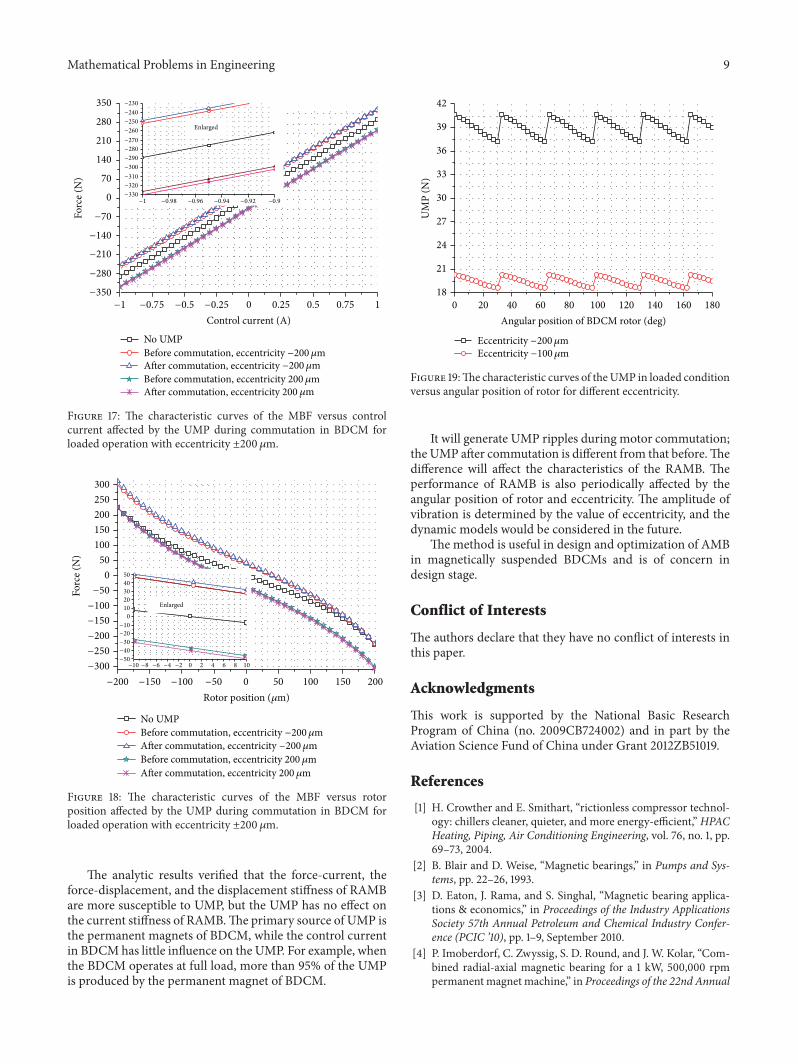