Embed Size (px)
Citation preview
Hindawi Publishing CorporationAdvances in Materials Science and EngineeringVolume 2013, Article ID 146896, 6 pageshttp://dx.doi.org/10.1155/2013/146896
Research ArticleThe Spot Weldability of Carbon Steel Sheet
A. M. Al-Mukhtar1,2 and Q. Doos3
1 Faculty of Geosciences and Geoengineering, Technische Universitat Bergakademie Freiberg, Gustav-Zeuner-Straße 12,09599 Freiberg, Germany
2 Baghdad University, Al-Khwarizmi College of Engineering, University of Baghdad, Baghdad, Iraq3 Baghdad University, College of Engineering, Baghdad, Iraq
Correspondence should be addressed to A. M. Al-Mukhtar; [email protected]
Received 12 May 2013; Revised 25 August 2013; Accepted 5 September 2013
Academic Editor: Daolun Chen
Copyright © 2013 A. M. Al-Mukhtar and Q. Doos. This is an open access article distributed under the Creative CommonsAttribution License, which permits unrestricted use, distribution, and reproduction in any medium, provided the original work isproperly cited.
The specimens of thickness 0.8mm carbon steel number 1.8902 in a strip form were welded. The strips of lap joints and curvedpeeljoints configurations have been welded. The welding parameters such as weld current and weld time have been investigated.The relation between the weld area and the joint strength properties has been presented. The obtained results were showing thatthe weld joint strength and the molten area (weld nugget volume) highly increase with the increasing of weld current. Therefore,the correlation between the maximum load (joint strength) and area has been given. The reliable weldability under the tensileand shearing loading was considered. Therefore, the new limits of weldability have been presented to consider these two types ofloading. Moreover, the experimental results were compared with the empirical relations that consider the sheet thickness only.
1. Introduction
Resistance spot welding (RSW) is the most widely commonmethod used for joining structures and plates of differentmaterials. This is because different joint configurations canbe made. The other advantage is the ability of machineautomatization. Therefore, the desired reliability of thesejoints can be made. Nevertheless, up to date, more works areneeded to investigate the materials, welding ability and thereliability of these joints under different loading.
However, carbon steel 1.8902 has been used in the auto-motive and industrial application; the weldability of carbonsteel; 1.8902 has been little investigated. The easy producingof sound spot welds by the convention tensile tests has beendetermined in different works [1–6]. The weld strength andweld nugget area that are related to the spot-welding variableswere investigated. In most cases, good spot-welding practicerequires three parameters that have to be controlled, namely,current, time, and electrode pressure [3].
Welding current passes through the joint interface toprovide the required heat for melting due to the gap resis-tance. The increase in current to critical limits would rapidly
increase in weld nugget strength, due to the increasing ofthe weld nugget area of mild steel [7]. The effect of theatmosphere which improves the tensile-shearing strengthwas investigated for the RSW of titanium sheets [5]. Theresponse of strength to increase in current is regular for thealuminum alloys spot welding [7]. Weld time is the secondvariable during which the current is allowed to flow. Weldtime for RSW is usually computed by the number of cycles asrecorded oscillographically.The convention electronic timerscan be used also by the second and converted to cycle (1 sec= 60 cycle). Reference [4] investigated only the optimumweld time for tensile peel and tensile shear joint of 1.2mmgalvanized chromate steel sheets. The variable resistance (𝑅)is influenced by the force applied (i.e., electrode pressure)through its effect on contact resistance [8, 9].The increases ofthe contact resistancewill increase the rate of heat generation.Therefore, the electrode pressure influences the heating ofthe joint primarily by affecting the contact resistance [7].In case the pressure automation was not available, theelectrode diameter could play the same rule. In this study, asystematic testing has been carried out to conduct the spot
2 Advances in Materials Science and Engineering
Table 1: Chemical composition of steel %.
Steel designation C Cr Ni Mn Si Fe16GS (1.8902) 0.15 0.3 0.3 2.2 0.2 Rem.
Table 2: Mechanical properties.
Tensile strength(MPa)
0.2% offset yieldstrengths Elongation Reduction of
area600 365MPa 19% 50%
weldability of carbon alloy steel (1.8902). This steel has beensuccessfully welded with a common spot-fusion process. Themicrostructural examination was not conducted since theaim of this work is to describe the weldability of the material.Therefore, a structural performance of the joint has beenpresented under tensile and shear loads.
2. Experimental Program
A tensile test was conducted for the lap and peel specimens.The specimens were welded using an electrode tip 4mmdiameter.The effect of welding variables on the joint strengthand weld area of the 1.8902 carbon steel has been categorizedfor both types of specimens [10].Theprogram includes tensiletest experiments to determine the spot weldability of carbonsteel under two differentmodes of stresses.The test procedureincludes the following.
(1) A set of peel and lap specimens were welded underdifferent welding condition (weld time and current).The electrode tip was 4mm.
(2) A static tensile test has been made to determine thejoint strength.Themaximum load is amajor propertyfrom the design point of view, and the weld nuggetarea has been measured. According to the thickness,the maximumweld current 7.2 kA was applied, wherethe expulsion can be observed. The samples joinedat a lower welding current of 3.7 kA will not have anenough weld size due to the smaller heat input.
2.1. Materials. The material employed in these testings con-sisted of a single sheet of carbon cold rolled steel (16GS,1.8902) with a nominal thickness (0.8mm). No surfacecoatingwas applied. Tables 1 and 2 show the chemical compo-sition and the mechanical properties, respectively.
2.2. Welding Equipment. The resistance spot welding equip-ment employed in this investigation was a standard footoperated rocker arm spotwelding (BayKay)with transformercapacity (15 kVA) and single phase (220 volt). Electrode waspure copper (RWMA class 1) which has a high thermaland electrical conductivity. Nevertheless, some mechanicalproperties are required. The dimensions were controlled bythe machining process for the electrode tips. Originally, theelectrodes were machined with a flat tip diameter of 4mmand body diameter of 16mm, and the tip angles were 30∘truncated cones.
Table 3: The welding process parameters.
Weld time(cycle)
Weld current(kA)
Electrodepressure (MPa)
Electrode force(N)
15, 30, 45, 60 3.7, 5.8, 6.7, 7.2 129 1617
The electrode tip diameter was selected according to theAmerican Welding Society (AWS) relationship [11]:
𝑑el = 0.1 + 2𝑡, (1)
where 𝑑el is the electrode tip diameter (in) and 𝑡 is thesheet thickness (in). This relationship may not be useful forthinner thickness ranges between 0.131 and 0.51mm and forthe thickness ranges between 3.18 and 12.7mm [11].
2.3. Welding Process. Thewelding process was carried out forthe specimen in specific dimensions; see Figure 1. The setsof welding specimens were made at different weld variables;see Table 3. At first, the weld time and electrode force werekept constant and varying the weld current subsequently.Moreover, the electrode tip diameter was fixed. Therefore,different welds joint properties were obtained. Four weldingtimes and currents were applied. Sixteen sets of specimensweremade. Each set consists of three specimens for each timeand current. Therefore, each point on the curves representsthe average of three reading values. Electrode force was setto be constant at 1617N. Hence, for the electrode diameterof 4mm, the electrode pressure was proposed to be equal to129MPa.
2.4. Tensile and Shearing Testing. Static strength was mea-sured using the conventional tensile shear lap specimens andpeel specimens. Specimen details and testing methods wereconfirmed by the AWS practice [12]. All welds were testedin tensile shear using a conventional hydraulic tensile testingmachine (Adamel Lhomrgy Dy. 25) model EG04. It wasequipped with a digital readout for both load and extension.The available function of the machine is to maintain both thepeak load and the weld strength [7, 13].
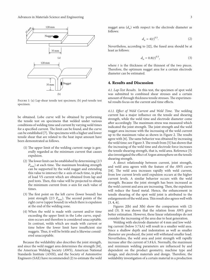
The lap shear specimen of two flat plates of 0.8mmthickness with an overlapping distance of 25mmwas welded,see Figure 1(a). The geometry was approximated as closely aspossible to pure shear made on the joint.
The peel mode specimen was subjected to a combinedstress created by joining the specimen distances away fromthe loading plane; see Figure 1(b). The stresses were a tensileload combined with moment around the weld point. Thebehavior was closely approximated to pure tension [7]. Theentire specimen dimensions were confirmed byAWSpractice[11].
3. Determination of Weldability
The spot weldability for 0.8mm carbon steel was determinedin the form of Lobe curves. This curve is plotted as weldtime versus weld current in one form of loading. It indicatesthe range of conditions in which satisfactory welds can
Advances in Materials Science and Engineering 3
Nugget
35mm
35mm 120mm
(a)
35mm
120mm
Nugget
(b)
Figure 1: (a) Lap-shear tensile test specimen; (b) peel-tensile testspecimen.
be obtained. Lobe curve will be obtained by performingthe tensile test on specimens that welded under variousconditions of welding time and current by varying weld timesfor a specified current. The limit can be found, and the curvecan be established [7].The specimens with a higher and lowertensile shear that are related to the heat input amount havebeen demonstrated as follows.
(1) The upper limit of the welding current range is gen-erally regarded as the minimum current that causesexpulsion.
(2) The lower limit can be established by determining (2/3𝑃max) at each time. The maximum breaking strengthcan be supported by the weld nugget and extendingthis value to intersect the 𝑥-axis of each time, in plotsof load VS current which are obtained from lap andpeel tests. Then, this value will be projected to obtainthe minimum current from 𝑥-axis for each value oftimes.
(3) The first point on the left curve (lower bound) hasjoint strength (2/3 𝑃max). The second points of theright curve (upper bound) in which there is expulsionat the end of the welding zone.
(4) When the weld is made with current and/or timeexceeding the upper limit in the Lobe curve, expul-sion occurs and therefore is considered unacceptable.In contrast, welds which are made with current ortime below the lower limit have insufficient sizenuggets. Thus, it will be brittle and is likewise consid-ered unacceptable.
Because the weldability also describes the joint strength,and since the weld nugget area determines the strength [14],the American Welding Society (AWS), American NationalStandards Institute (ANSI), and the Society of AutomotiveEngineers (SAE) have recommended (2) to estimate the weld
nugget area (𝑑𝑛) with respect to the electrode diameter as
follows:
𝑑𝑛= 4(𝑡)
0.5
. (2)
Nevertheless, according to [12], the fused area should be atleast as follows:
𝑑𝑛= 0.8(𝑡)
0.5
, (3)
where 𝑡 is the thickness of the thinnest of the two pieces.Therefore, the optimum nugget area for a certain electrodediameter can be estimated.
4. Results and Discussion
4.1. Lap-Test Results. In this test, the specimen of spot weldwas submitted to combined shear stresses and a certainamount of through thickness tensile stresses.The experimen-tal results focus on the current and time effects.
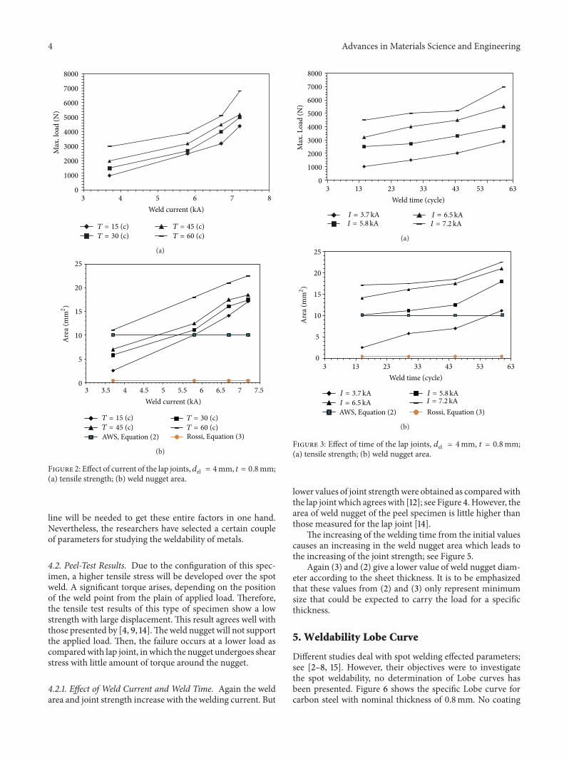
4.1.1. Effect of Weld Current and Weld Time. The weldingcurrent has a major influence on the tensile and shearingstrength, while the weld time and electrode diameter comeafter accordingly. The maximum stress was measured whichindicated the joint strength. The joint strength and the weldnugget area increase with the increasing of the weld currentup to the maximum value as shown in Figure 2. The resultsagree with [6].The same behavior was obtained by increasingthe weld time; see Figure 3.The result from [5] has shown thatthe increasing of the weld time and electrode force increasesthe tensile shearing strength, that is, weld area. Reference [5]also investigated the effect of Argon atmosphere on the tensileshearing strength.
A direct relationship between current, joint strength,and weld area agrees with the feature of the AWS curve[14]. The weld area increases rapidly with weld current,from low current levels until expulsion occurs at the highercurrent levels. A similar behavior occurs with the weldstrength. Because the joint strength has been increased asthe weld current and area are increasing.Then, the expulsionwill reduce the fused metal. Hence, the enhancement intensile shearing of the spot weld joint is attributed to theenlargements of theweld area.This result also agreeswell with[3, 4, 6].
Figures 2(b) and 3(b) show the comparison with (2)and (3). It was shown that the relation from AWS givesbetter estimation. However, these linear relationships do notconsider the increasing of the area due to heat generation.
Welding with electrode diameter of 4mm and low weld-ing current (below 3.7 kA) will result in a smaller weld area.Since a shallow depth and indentation as well as smallerdiameter are produced, the joint will withstand smaller load.Nevertheless, the weld area and joint strength will rapidlyincrease after the current of 5.8 kA. Normally, the maximumand minimum welding parameters are influenced by anddependent on the product geometry, machine type anddesign, and electrode materials and design. Therefore, theweldability investigation of a certain material in a production
4 Advances in Materials Science and Engineering
876543
8000
7000
6000
5000
4000
3000
2000
0
1000
Weld current (kA)
Max.
load
(N)
T = 15 (c)T = 30 (c)
T = 45 (c)T = 60 (c)
(a)
AWS, Equation (2)
Weld current (kA)
Are
a (m
m2)
3 3.5 4 4.5 5 5.5 6 6.5 7 7.5
25
20
15
10
5
0
T = 15 (c)T = 45 (c)
T = 30 (c)T = 60 (c)Rossi, Equation (3)
(b)
Figure 2: Effect of current of the lap joints, 𝑑el = 4mm, 𝑡 = 0.8mm;(a) tensile strength; (b) weld nugget area.
line will be needed to get these entire factors in one hand.Nevertheless, the researchers have selected a certain coupleof parameters for studying the weldability of metals.
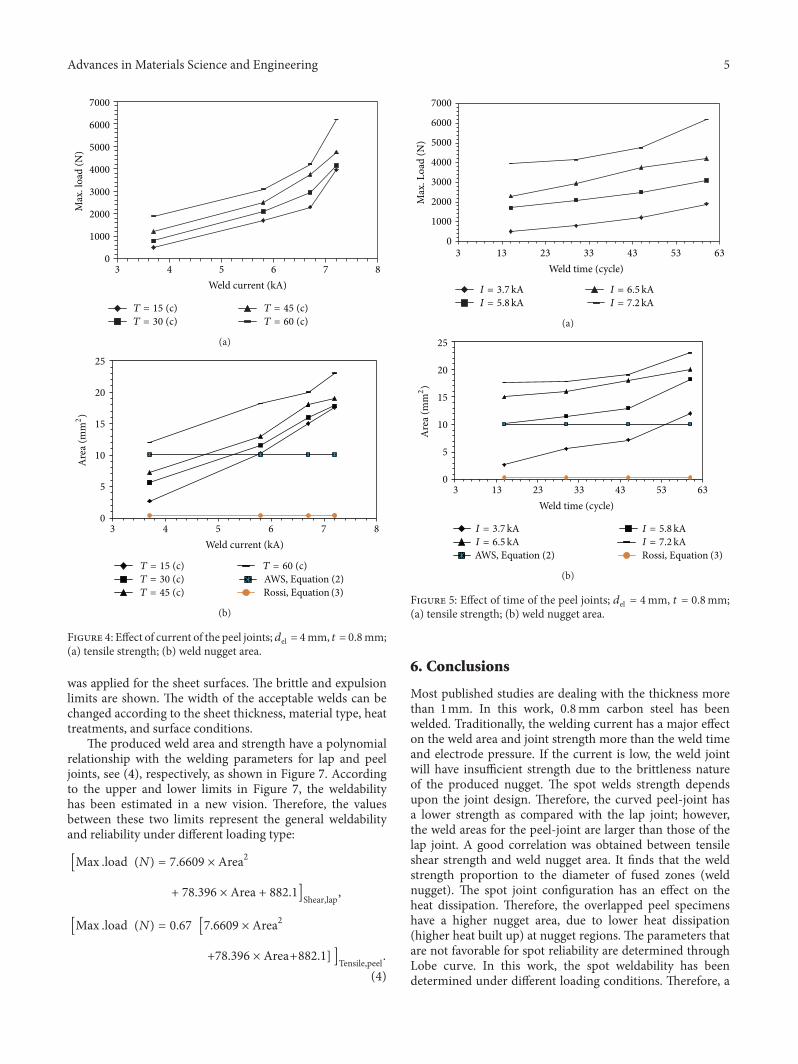
4.2. Peel-Test Results. Due to the configuration of this spec-imen, a higher tensile stress will be developed over the spotweld. A significant torque arises, depending on the positionof the weld point from the plain of applied load. Therefore,the tensile test results of this type of specimen show a lowstrength with large displacement. This result agrees well withthose presented by [4, 9, 14].Theweld nugget will not supportthe applied load. Then, the failure occurs at a lower load ascomparedwith lap joint, in which the nugget undergoes shearstress with little amount of torque around the nugget.
4.2.1. Effect of Weld Current and Weld Time. Again the weldarea and joint strength increase with the welding current. But
Weld time (cycle)
Max.
Load
(N)
6343233
8000
7000
6000
5000
4000
3000
2000
1000
0
I = 5.8kAI = 3.7kA I = 6.5 kA
I = 7.2kA
13 33 53
(a)
I = 7.2 kAI = 6.5kAI = 5.8kAI = 3.7kA
Weld time (cycle)
Are
a (m
m2)
6343233
5
10
15
20
25
AWS, Equation (2)
13 33 53
0
Rossi, Equation (3)
(b)
Figure 3: Effect of time of the lap joints, 𝑑el = 4mm, 𝑡 = 0.8mm;(a) tensile strength; (b) weld nugget area.
lower values of joint strengthwere obtained as comparedwiththe lap joint which agreeswith [12]; see Figure 4.However, thearea of weld nugget of the peel specimen is little higher thanthose measured for the lap joint [14].
The increasing of the welding time from the initial valuescauses an increasing in the weld nugget area which leads tothe increasing of the joint strength; see Figure 5.
Again (3) and (2) give a lower value of weld nugget diam-eter according to the sheet thickness. It is to be emphasizedthat these values from (2) and (3) only represent minimumsize that could be expected to carry the load for a specificthickness.
5. Weldability Lobe Curve
Different studies deal with spot welding effected parameters;see [2–8, 15]. However, their objectives were to investigatethe spot weldability, no determination of Lobe curves hasbeen presented. Figure 6 shows the specific Lobe curve forcarbon steel with nominal thickness of 0.8mm. No coating
Advances in Materials Science and Engineering 5
Weld current (kA)
Max.
load
(N)
876543
7000
6000
5000
4000
3000
2000
1000
0
T = 15 (c)T = 30 (c)
T = 45 (c)T = 60 (c)
(a)
Rossi, Equation (3)
AWS, Equation (2)
Weld current (kA)
Are
a (m
m2)
876543
25
20
15
10
5
0
T = 15 (c)T = 30 (c)T = 45 (c)
T = 60 (c)
(b)
Figure 4: Effect of current of the peel joints; 𝑑el = 4mm, 𝑡 = 0.8mm;(a) tensile strength; (b) weld nugget area.
was applied for the sheet surfaces. The brittle and expulsionlimits are shown. The width of the acceptable welds can bechanged according to the sheet thickness, material type, heattreatments, and surface conditions.
The produced weld area and strength have a polynomialrelationship with the welding parameters for lap and peeljoints, see (4), respectively, as shown in Figure 7. Accordingto the upper and lower limits in Figure 7, the weldabilityhas been estimated in a new vision. Therefore, the valuesbetween these two limits represent the general weldabilityand reliability under different loading type:
[Max .load (𝑁) = 7.6609 × Area2
+ 78.396 × Area + 882.1]Shear,lap,
[Max .load (𝑁) = 0.67 [7.6609 × Area2
+78.396 × Area+882.1] ]Tensile,peel.(4)
I = 7.2kAI = 6.5kA
I = 5.8kAI = 3.7kA
Weld time (cycle)
Max.
Load
(N)
6343233
7000
6000
5000
4000
3000
2000
1000
0
13 33 53
(a)
Rossi, Equation (3)AWS, Equation (2)I = 7.2kAI = 6.5kAI = 5.8kAI = 3.7kA
Weld time (cycle)
Are
a (m
m2)
6343233
25
20
15
10
5
013 33 53
(b)
Figure 5: Effect of time of the peel joints; 𝑑el = 4mm, 𝑡 = 0.8mm;(a) tensile strength; (b) weld nugget area.
6. Conclusions
Most published studies are dealing with the thickness morethan 1mm. In this work, 0.8mm carbon steel has beenwelded. Traditionally, the welding current has a major effecton the weld area and joint strength more than the weld timeand electrode pressure. If the current is low, the weld jointwill have insufficient strength due to the brittleness natureof the produced nugget. The spot welds strength dependsupon the joint design. Therefore, the curved peel-joint hasa lower strength as compared with the lap joint; however,the weld areas for the peel-joint are larger than those of thelap joint. A good correlation was obtained between tensileshear strength and weld nugget area. It finds that the weldstrength proportion to the diameter of fused zones (weldnugget). The spot joint configuration has an effect on theheat dissipation. Therefore, the overlapped peel specimenshave a higher nugget area, due to lower heat dissipation(higher heat built up) at nugget regions. The parameters thatare not favorable for spot reliability are determined throughLobe curve. In this work, the spot weldability has beendetermined under different loading conditions. Therefore, a

6 Advances in Materials Science and Engineering
Acceptableweld
Brittle side Expulsion side
Current (kA)
Tim
e (cy
cle)
87654
70
60
50
40
30
20
10
0
Figure 6: Lobe curve; 𝑑el = 4mm, 𝑡 = 0.8mm, lap joint.
Relation equation-peelRelation equation-lapI = 7.2 kA
I = 6.7kAI = 5.8kAI = 3.7kA
Weld area (mm2)
Max.
load
(N)
2520151050
7000
6000
5000
4000
3000
2000
1000
0
Figure 7: The relation between weld area and joint strength for lapand peel joints.
better reliability can be determined for specificmaterials.Theminimum weld area that is needed for specific thickness wascomparedwith the experiments results. Hence, theminimumweld area was determined as compared with AWS relationand experiments.
Acknowledgments
The first author would like to thankfully appreciate thesupport received from the Technische Universitaet Bergak-ademie Freiberg, Institute of Hydrology, Faculty of Geo-sciences and Geoengineering. The support from the Instituteof International Education (IIE), USA, is gratefully appreci-ated.
References
[1] S.W. Gibson,AdvancedWelding, Macmillan, London, UK, 1997.[2] J. M. Sawhill Jr. and J. C. Baker, “Spot weldability of high-
strength sheet steels,”Welding Journal, vol. 59, no. 1, 1980.[3] J. M. Sawhill Jr., H. Watanabe, and J. W. Mitchell, “Spot
weldability of Mn Mo Cb, V–N and SAE 1008 steels,” WeldingJournal, vol. 56, no. 7, 1977.
[4] S. Aslanlar, A. Ogur, U. Ozsarac, E. Ilhan, and Z. Demir, “Effectof welding current on mechanical properties of galvanizedchromided steel sheets in electrical resistance spot welding,”Materials and Design, vol. 28, no. 1, pp. 2–7, 2007.
[5] N.Kahraman, “The influence ofwelding parameters on the jointstrength of resistance spot-welded titanium sheets,” Materialsand Design, vol. 28, no. 2, pp. 420–427, 2007.
[6] D. Ozyurek, “An effect of weld current and weld atmosphere onthe resistance spot weldability of 304 L austenitic stainless steel,”Materials and Design, vol. 29, no. 3, pp. 597–603, 2008.
[7] D. K. Aidun and R. W. Bennett, “Effect of resistance weldingvariables on the strength of spot welded 6061-T6 Aluminumalloy,”Welding Journal, vol. 64, no. 12, pp. 15–25, 1985.
[8] D. R. Andrews, “The importance of monitoring resistancewelding parameters,”Welding andMetal Fabrication, vol. 54, no.3, pp. 121–122, 1986.
[9] P. K. Ray and B. B. Verma, “A study on spot heating inducedfatigue crack growth retardation,” Fatigue and Fracture ofEngineering Materials and Structures, vol. 28, no. 7, pp. 579–585,2005.
[10] S. Aslanlar, A. Ogur, U. Ozsarac, and E. Ilhan, “Weldingtime effect on mechanical properties of automotive sheets inelectrical resistance spot welding,”Materials andDesign, vol. 29,no. 7, pp. 1427–1431, 2008.
[11] A. W. Society,Welding, Welding Handbook, 4th Edition, Sec. (2),1958.
[12] B. E. Rossi,Welding Engineering, McGraw-Hill, New York, NY,USA, 1954.
[13] J. Dufourny and A. Bragard, “Resistance spot welding of highstrength low alloy steel (HSLA) sheet, a survey,”Welding in theWorld, Le Soudage Dans Le Monde, vol. 23, no. 5-6, pp. 100–123,1985.
[14] H. Moshayedi and I. Sattari-Far, “Numerical and experimen-tal study of nugget size growth in resistance spot weldingof austenitic stainless steels,” Journal of Materials ProcessingTechnology, vol. 212, no. 2, pp. 347–354, 2012.
[15] T. Uwaba, Y. Yano, and M. Ito, “Resistance spot weldabilityof 11Cr-ferritic/martensitic steel sheets,” Journal of NuclearMaterials, vol. 421, no. 1–3, pp. 132–139, 2012.

Submit your manuscripts athttp://www.hindawi.com
ScientificaHindawi Publishing Corporationhttp://www.hindawi.com Volume 2014
CorrosionInternational Journal of
Hindawi Publishing Corporationhttp://www.hindawi.com Volume 2014
Polymer ScienceInternational Journal of
Hindawi Publishing Corporationhttp://www.hindawi.com Volume 2014
Hindawi Publishing Corporationhttp://www.hindawi.com Volume 2014
CeramicsJournal of
Hindawi Publishing Corporationhttp://www.hindawi.com Volume 2014
CompositesJournal of
NanoparticlesJournal of
Hindawi Publishing Corporationhttp://www.hindawi.com Volume 2014
Hindawi Publishing Corporationhttp://www.hindawi.com Volume 2014
International Journal of
Biomaterials
Hindawi Publishing Corporationhttp://www.hindawi.com Volume 2014
NanoscienceJournal of
TextilesHindawi Publishing Corporation http://www.hindawi.com Volume 2014
Journal of
NanotechnologyHindawi Publishing Corporationhttp://www.hindawi.com Volume 2014
Journal of
CrystallographyJournal of
Hindawi Publishing Corporationhttp://www.hindawi.com Volume 2014
The Scientific World JournalHindawi Publishing Corporation http://www.hindawi.com Volume 2014
Hindawi Publishing Corporationhttp://www.hindawi.com Volume 2014
CoatingsJournal of
Advances in
Materials Science and EngineeringHindawi Publishing Corporationhttp://www.hindawi.com Volume 2014
Smart Materials Research
Hindawi Publishing Corporationhttp://www.hindawi.com Volume 2014
Hindawi Publishing Corporationhttp://www.hindawi.com Volume 2014
MetallurgyJournal of
Hindawi Publishing Corporationhttp://www.hindawi.com Volume 2014
BioMed Research International
MaterialsJournal of
Hindawi Publishing Corporationhttp://www.hindawi.com Volume 2014
Nano
materials
Hindawi Publishing Corporationhttp://www.hindawi.com Volume 2014
Journal ofNanomaterials