Embed Size (px)
Citation preview
Research ArticleStudy on the Behaviors of a Conceptual PassiveContainment Cooling System
Jianjun Wang, Xueqing Guo, Shengzhi Yu, Baowei Cai, Zhongning Sun, and Changqi Yan
National Defense Key Laboratory for Nuclear Safety and Simulation Technology, Harbin Engineering University, Harbin 150001, China
Correspondence should be addressed to Jianjun Wang; [email protected]
Received 19 November 2013; Revised 11 February 2014; Accepted 12 February 2014; Published 26 March 2014
Academic Editor: Li Shengqiang
Copyright © 2014 Jianjun Wang et al. This is an open access article distributed under the Creative Commons Attribution License,which permits unrestricted use, distribution, and reproduction in any medium, provided the original work is properly cited.
The containment is an ultimate and important barrier tomitigate the consequences after the release of mass and energy during suchscenarios as loss of coolant accident (LOCA) or main steam line break (MSLB). In this investigation, a passive containment coolingsystem (PCCS) concept is proposed for a large dry concrete containment. The system is composed of series of heat exchangers,long connecting pipes with relatively large diameter, valves, and a water tank, which is located at the top of the system and servesas the final heat sink. The performance of the system is numerically studied in detail under different conditions. In addition, theinfluences of condensation heat transfer conditions and containment environment temperature conditions are also studied onthe behaviors of the system. The results reveal that four distinct operating stages could be experienced as follows: startup stage,single phase quasisteady stage, flashing speed-up transient stage, and flashing dominated quasisteady operating stage. Furthermore,the mechanisms of system behaviors are thus analyzed. Moreover, the feasibility of the system is also discussed to meet thedesign purpose for the containment integrity requirement. Considering the passive feature and the compactness of the system,the proposed PCCS is promising for the advanced integral type reactor.
1. Introduction
In order to prevent the radioactive species escaping toatmosphere, high integrity containment has been one of themost active design focuses in recent years. Under the internaleffects of such design basis accidents scenarios as loss ofcoolant (LOCA) and main steam line break (MSLB), theexpansion and transport of high mass/energy releases intothe containment free volume will make the pressure and thetemperature increase (Tills et al. [1]). In conventional nuclearpower plant, the sprays and/or fan coolers are employed tocontrol the containment peak pressure and temperature forensuring the integrity of the containment. However, eithersprays or fan coolers are dependent on the power supply,which is unreliable if LOCA or MSLB scenarios are coupledwith the loss of power supply.Moreover, if there is no effectiveway to transfer the energy, the pressure and the temperaturein the containment may exceed the allowed value. Therefore,theremay be potential risks for the containment integrity. Tillnow, there have been worldwide efforts to develop promisingpassive containment cooling systems which are much safer,
more reliable, and possibly simpler than traditional designsas spray and/or fan cooler systems.
There are several conceptual candidate passive con-tainment cooling systems which have been proposed andstudied to date for either steel or dry double-wall concretecontainment configuration of interest. For example, passivecontainment cooling by natural circulation and air convec-tion and thermal radiation has been proposed for AP600(Tower et al. [2]) and AP1000 (Schulz [3]) reactors. Gavrilaset al. [4] proposed a containment design concept, in whichheat rejection through the steel shell was enhanced by usingan air-convection annulus on the upper portion and anexternal moat on the lower portion.
However, as compared to steel containment design forAP600 or AP1000, it may be more difficult to remove theenergy released in the accidents from a concrete containmentdue to the lower thermal conductivity of the concrete thansteel.
Thus, a passive containment cooling system may bepreferable and essential for the safety of containment in harshpostaccident conditions, which is completely independent of
Hindawi Publishing CorporationScience and Technology of Nuclear InstallationsVolume 2014, Article ID 358365, 8 pageshttp://dx.doi.org/10.1155/2014/358365
2 Science and Technology of Nuclear Installations
mechanical, electrical, instrumentation, and control system.There are several conceptual candidate passive containmentcooling systems which have been proposed and studiedto date for the large dry double-wall concrete contain-ment configuration of interest. Ahmad et al. [5] raised aheat pipe design concept for a passive containment heatremoval system. Forsberg and Conklin [6] presented a so-called temperature-initiated passive cooling system. A ther-mosyphon loop concept for double-shell concrete contain-ment was developed by ENEL. Similarly, Leiendecker et al.[7] had investigated another thermosyphon type conceptualcontainment cooling system. On the basis of thermosyphontype design schemes, Byun et al. [8] raised an internalevaporator-only (IEO) concept and the performance of thesystem was then investigated with the GOTHIC computercode. They concluded that four IEO loops could be utilizedto meet design criteria for severe accident scenarios. In 2000,Liu et al. [9] performed an experimental investigation fora passive IEO cooling unit, in which the condensation heattransfer coefficients are thoroughly studied.
Enlightened by IEO design concept, we present an open-loop passive containment cooling system (OLPCCS) concept,which is composed of heat exchangers located in the contain-ment, long connecting pipes with relatively large diameter,valves, and one water tank located outside the containment.The proposed system may operate by natural circulationmeans and free of pumps or other power supplies. TheOLPCCS is designed to serve as the accidental consequencemitigation for the large dry containments of conventionalPWRs. The OLPCCS is designed to control the pressure andthe temperature in the containment after some accidents. Assuch, the operating pressure of the proposed system mustbe lower than permitted pressure in the containment dueto heat transfer requirement, which means the OLPCCSis a system with very low pressure (near to atmospherepressure). At present, most investigations on the behaviors ofthe natural circulation under low-pressure conditions werecontributing to the studies of either start-up procedures tocross the instability region (Jiang et al. [10], van der Hagenand Stekelenburg [11],Manera et al. [12], andKuran et al. [13])or two-phase flow instabilities (Aguirre et al. [14], Aritomiet al. [15], Van Bragt and van der Hagen [16], Guanghuiet al. [17], etc.) for the boiling water reactors (BWRs). Amongthese studies, the authors were dealing with the performanceof closed loop natural circulation system which was ratherdifferent from OLPCCS. Furthermore, several codes weredeveloped to study the flow instabilities which may occurin those natural circulation systems in time domain orfrequency domain (Inada et al. [18] and Van Bragt et al. [19]).Even though thermal-hydraulic codes had been used forthe numerical simulations of natural circulation with lowerpressure (Tiselj and Cerne [20], Kozmenkov et al. [21], andMangal et al. [22]), it is still debatable for the validation ofthose codes in this field.
Thus, it is clear that there is not proper code for the sim-ulation of operating behaviors of such a natural circulationsystem asOLPCCS.Therefore, this paper addresses themodelon the basis of HEM formulation for two-phase flow. Themodel allows for the thermal properties change, which is
calculated with open code package named WASPCN, alongthe flow path both in single phase and two-phase zone. Theone-dimensional computational code is developed by incor-porating the above-mentionedmodel in order to numericallyinvestigate the operation characteristics of the OLPCCS.With the code, transient flow behaviors are simulated fromstartup to quasisteady state and from single phase flow totwo-phase flow. Besides, the heat removal capabilities of thesystem are also analyzed.
2. OLPCCS
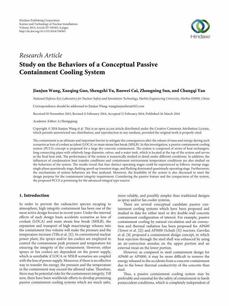
The schematic of OLPCCS design and the structure of theheat exchangers are shown in Figure 1. The heat exchangerinside the containment is supposed to be located along thecontainment perimeter. With the consideration of compo-nents arrangement inside the containment, the heat exchang-ers ofOLPCCS are designed to locate above the ring lifting. Inorder to eliminate the influence between the bundles duringcondensation, the heat exchanger can be designed as singlerow configuration. The heat exchanger is connected to thewater tank through pipes with valves.
Some of the design parameters of the OLPCCS are listedin Table 1.
As shown in Figure 1, in the event of a LOCA or MSLB,the coolant released from the reactor vessel or steam linewill be flashing into the containment because of the suddendecrease of the pressure. Afterwards, the mixture composedof steam and air may be cooled through the heat exchangerslocated inside the containment. Meanwhile, the fluid in thetubes of the heat exchangers will be heated up, which willsupply the original driving force for the natural circulationof OLPCCS.
3. Model Setup
In this paper, the following conditions are assumed.
(1) The heat can only be exchanged via the heat exchang-ers, which means the connecting pipes are adiabatic.
(2) The OLPCCS is isothermal when it is standing by.
(3) The heat transfer coefficient remains constant alongthe tubes except in phase change scenario.
(4) When the OLPCCS is activated, the temperature inthe containment steps to and remains some specificvalue.
(5) Both steam and the liquid in the system are incom-pressible.
The homogeneous two-phase flow model is used in thispaper. The main conservation equations are listed as follows.
Mass conservation equation:
𝜕𝑊𝑚
𝜕𝑧= 0. (1)
Science and Technology of Nuclear Installations 3
Figure 1: Schematic of OLPCCS (not to scale).
Table 1: Parameters of OLPCCS unit.
Parameter ValueHeight of heat exchanger/m 5.0Height difference between the in-containment heatexchanger and water tank/m 10
Area of one heat exchanger/m2 300Initial water temperature/∘C 30∼70Condensation heat transfer coefficient/(W/(m2K)) 500∼1000
Momentum conservation equation:
𝜕𝑊𝑚
𝜕𝑡+𝜕 (𝑊2
𝑚/ (𝐴𝜌𝑚))
𝜕𝑧
= −𝑑𝑝
𝑑𝑧+ (
𝑑𝑝
𝑑𝑧)
𝑓
+ (𝑑𝑝
𝑑𝑧)
𝑔
+ (𝑑𝑝
𝑑𝑧)
𝑙
.
(2)
Energy conservation equation:
𝐴𝜕 (ℎ𝑚𝜌𝑚)
𝜕𝑡+𝜕 (𝑊𝑚ℎ𝑚)
𝜕𝑧= 𝑞𝑙, (3)
where𝑊𝑚is themass flow rate, kg/s;𝐴 is flow area, m2; 𝜌
𝑚is
the average density of the mixture, kg/m3; ℎ𝑚is the enthalpy
of mixture, kJ/kg; 𝑞𝑙denotes the linear power, W/m.
The main constitutive relationships used in the paper areas follows, which include the pressure drop and heat transfercalculation expression:
Δ𝑝𝑓,sp = 𝑓
𝐿
𝑑𝑖
𝜌𝑢2
2, (4)
where
𝑓 =
{{{{{
{{{{{
{
64
ReRe ≤ 2000
0.3164Re−0.25 2000 < Re ≤ 3.0 × 10⁴
0.184Re−0.2 3.0 × 10⁴
< Re ≤ 2.1 × 10⁶
0.01 Re > 2.1 × 10⁶,
(5)
Δ𝑝𝑓,tp = 𝜙
2
𝑙0𝑓𝐿
𝑑𝑖
𝜌𝑢2
2. (6)
In (6), 𝜙2𝑙0denotes the two-phase friction multiplier, which
can be expressed as follows:
𝜙2
𝑙0= [1 + 𝑥(
𝜌𝑙
𝜌𝑔
− 1)] , (7)
or Baroczy method is used for the calculation of 𝜙2𝑙0.
If the convection heat transfer is in single liquid phase,then
Nu = {3.66 Re ≤ 20000.023Re0.8Pr0.4 Re > 2000,
(8)
where Nu = ℎsp𝑑𝑖/𝑘.The boiling heat transfer coefficient is calculated with the
correlations recommended by Shah [23]:
ℎtp = ℎsp (ℎBL + ℎCL) , (9)
where ℎtp is the boiling heat transfer coefficient, W/(m2K):
ℎBL = {230Bo0.5 Bo > 0.00031 + 46Bo0.5 Bo < 0.0003;
ℎCL =1.8
𝐶0.80
.
(10)
PCCSTS (passive containment cooling system transientsimulation) code is developed with the finite differencemethod (FDM) based on the models. The schematic ofthe control volumes of main parts of the system is shownin Figure 2. The numerical simulation of behaviors of theOLPCCS is performed with PCCSTS code. In the currentstudy, the time step for the transient analysis is set to 0.01 sand the converging criteria of the calculations are set to lessthan 1.0𝑒 − 6 in terms of relative error.
4. Results and Discussions
4.1. Overall Operating Behaviors of OLPCCS. From the con-servation point of view, it is supposed that the temperature
4 Science and Technology of Nuclear Installations
Riser
Downcomer
Heatexchanger
Watertank
Atmosphere
Connecting pipe
Figure 2: Schematic of the nodalization.
0 5000 10000 15000
0
10
20
30
40
11 12 13 14 158
1216202428
Mas
s flow
rate
Time (s)
Mass flow rate
AB C D
×103
(kg/
s)
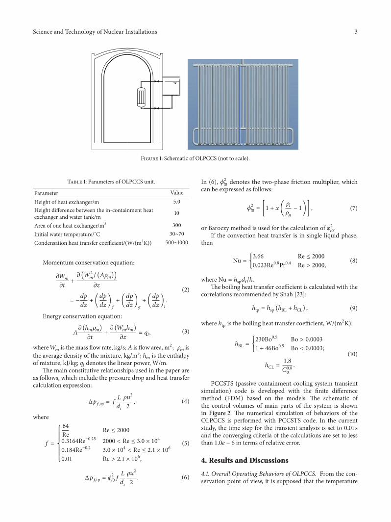
Figure 3: Mass flow rate evolution after OLPCCS being activated.
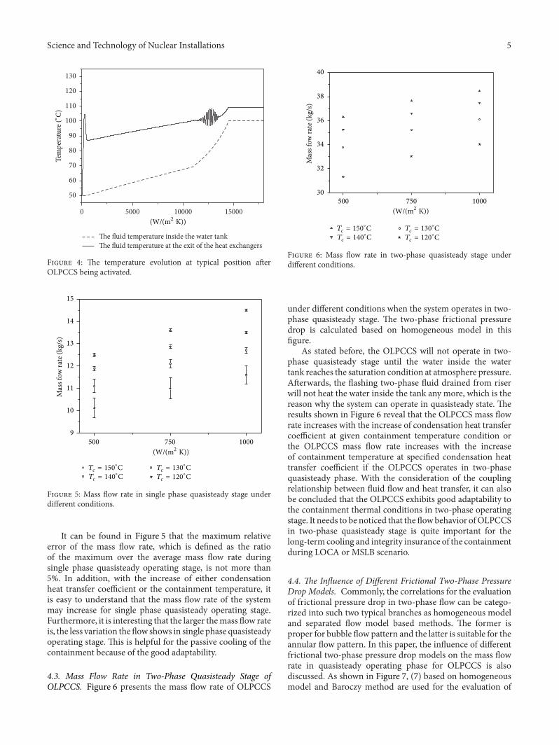
inside the containment steps from the same value as thatinside water tank to some value and remains afterward.Firstly, such case is studied that the OLPCCS remainsstanding by with the water tank temperature of 50∘C and isactivated and the temperature inside the containment steps to150∘C since then. According to the study of Liu et al. [9] thecondensation heat transfer coefficient of steam in the pres-ence of incondensable air changes from about 500W/(m2K)to almost 2500W/(m2K). From conservation point of view,the heat transfer coefficient is set to 500W/(m2K)in this case.Furthermore, the height difference between the water tankand the heat exchanger is 10. Figure 3 depicts the mass flowrate evolution of the OLPCCS in time after being activated.
It can be found that the mass flow rate will increasequickly after the system is activated. With the temperatureinside the containment suddenly increasing from 50∘C to150∘C, the fluid in the heat exchanger will be heated up simul-taneously and its temperature gradually increases, which will
make the density difference of the fluid between downwardpipe and the riser pipes. Therefore, the force generating fromthe density difference drives the fluid to move along theloop. During the early stage in startup process, denoted asA in Figure 3, the velocity grows faster and faster, which isbecause the flow enhances the heat transfer capacity of theheat exchanger and the driving force increases consequently.After the OLPCCS fully starts up, the system operates insingle phase mode and the mass flow rate remains barelyconstant for a relatively long time as shown in Figure 3 withB.Therefore, the period of operation is named as single phasequasisteady stage. During single phase quasisteady operatingstage, the fluid that flows through the heat exchangersmaintains single phase along all the pipes, even if the systemis heated up gradually. Moreover, the fluid temperaturedifference between inlet and outlet of the heat exchangerschanges very slowly. Therefore, the driving force and themass flow rate of the system are almost changeless. With theincrease of the fluid temperature inside the water tank, thetemperature increases at the exit of the heat exchangers andreaches saturation point at the outlet of the riser. This causesthe flashing of the fluid and then results in the sharp increaseof driving force for natural circulation of the system. Thus,the mass flow rate of the system begins to increase when theflashing occurs in the riser. Alongwith the development of theflashing downward, the system is being speeded upmore andmore. However, the speeding up process will not continue allthe time because the quick increasing velocity may have theeffects in two aspects: (1) it will help enhance the heat transfercapability of the heat exchanger; (2) it also may result in thedecrease of outlet temperature because of highmass flow rate.Furthermore, the coupling and the lag effect between heattransfer and fluid flow result in the oscillation occurrence.Under given conditions, the oscillation of the mass flow ratewill vanish when the temperature of the fluid inside the watertank reaches 90∘Cas shown in Figure 4. After that, the naturalcirculation capability will be enhanced continuously until thefluid reaches the saturate temperature inside the water tank.This transient process denoted as C in Figure 3 is named asflashing speed-up transient stage. Finally, the system operatesin two-phase quasisteady mode and is dominated by flashingwhich supplies the main driving head for the system. Thisstage is marked as D in Figure 3.
According to the description of the operating stages forOLPCCS, it can be concluded that there are two transientphases and two quasisteady phases fromA to D. From systemdesign point of view, quasisteady operating stages, markedwith B and D, make sense as far as the long-term cooling isconcerned in single phase and two-phase mode, respectively.Hence, the flow characteristics of both single phase andflashing dominated two-phase quasisteady stages are studiedin the following parts.
4.2. Mass Flow Rate in Single Phase Quasisteady Stage ofOLPCCS. Figure 5 shows the mass flow rate in single phasequasisteady stage of OLPCCS under different conditions,which include different condensation heat transfer coeffi-cients and different containment temperatures.
Science and Technology of Nuclear Installations 5
0 5000 10000 15000
50
60
70
80
90
100
110
120
130
The fluid temperature inside the water tankThe fluid temperature at the exit of the heat exchangers
Tem
pera
ture
(∘C)
(W/(m2 K))
Figure 4: The temperature evolution at typical position afterOLPCCS being activated.
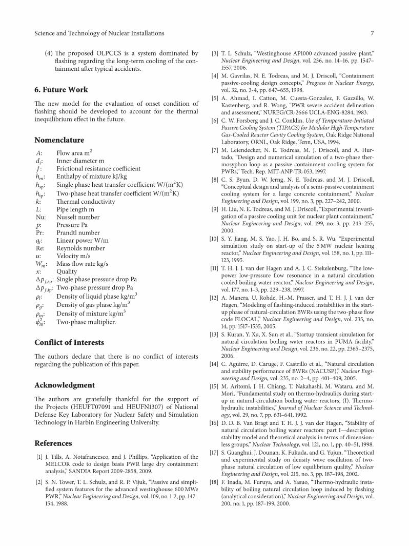
500 750 10009
10
11
12
13
14
15
Mas
s fow
rate
(kg/
s)
Tc = 150∘C
Tc = 140∘C
Tc = 130∘C
Tc = 120∘C
(W/(m2 K))
Figure 5: Mass flow rate in single phase quasisteady stage underdifferent conditions.
It can be found in Figure 5 that the maximum relativeerror of the mass flow rate, which is defined as the ratioof the maximum over the average mass flow rate duringsingle phase quasisteady operating stage, is not more than5%. In addition, with the increase of either condensationheat transfer coefficient or the containment temperature, itis easy to understand that the mass flow rate of the systemmay increase for single phase quasisteady operating stage.Furthermore, it is interesting that the larger themass flow rateis, the less variation the flow shows in single phase quasisteadyoperating stage. This is helpful for the passive cooling of thecontainment because of the good adaptability.
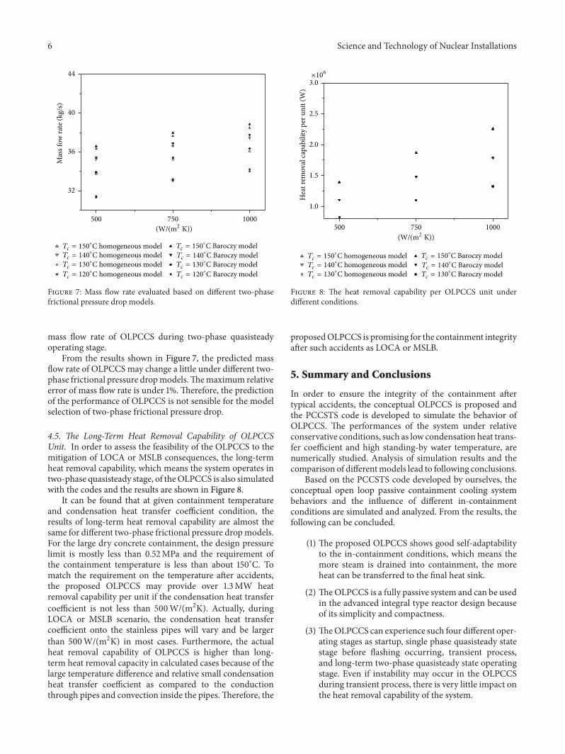
4.3. Mass Flow Rate in Two-Phase Quasisteady Stage ofOLPCCS. Figure 6 presents the mass flow rate of OLPCCS
500 750 100030
32
34
36
38
40
Mas
s fow
rate
(kg/
s)
Tc = 150∘C
Tc = 140∘C
Tc = 130∘C
Tc = 120∘C
(W/(m2 K))
Figure 6: Mass flow rate in two-phase quasisteady stage underdifferent conditions.
under different conditions when the system operates in two-phase quasisteady stage. The two-phase frictional pressuredrop is calculated based on homogeneous model in thisfigure.
As stated before, the OLPCCS will not operate in two-phase quasisteady stage until the water inside the watertank reaches the saturation condition at atmosphere pressure.Afterwards, the flashing two-phase fluid drained from riserwill not heat the water inside the tank any more, which is thereason why the system can operate in quasisteady state. Theresults shown in Figure 6 reveal that the OLPCCS mass flowrate increases with the increase of condensation heat transfercoefficient at given containment temperature condition orthe OLPCCS mass flow rate increases with the increaseof containment temperature at specified condensation heattransfer coefficient if the OLPCCS operates in two-phasequasisteady phase. With the consideration of the couplingrelationship between fluid flow and heat transfer, it can alsobe concluded that the OLPCCS exhibits good adaptability tothe containment thermal conditions in two-phase operatingstage. It needs to be noticed that the flowbehavior ofOLPCCSin two-phase quasisteady stage is quite important for thelong-term cooling and integrity insurance of the containmentduring LOCA or MSLB scenario.
4.4. The Influence of Different Frictional Two-Phase PressureDrop Models. Commonly, the correlations for the evaluationof frictional pressure drop in two-phase flow can be catego-rized into such two typical branches as homogeneous modeland separated flow model based methods. The former isproper for bubble flow pattern and the latter is suitable for theannular flow pattern. In this paper, the influence of differentfrictional two-phase pressure drop models on the mass flowrate in quasisteady operating phase for OLPCCS is alsodiscussed. As shown in Figure 7, (7) based on homogeneousmodel and Baroczy method are used for the evaluation of
6 Science and Technology of Nuclear Installations
500 750 1000
32
36
40
44
Mas
s fow
rate
(kg/
s)
Tc = 150∘C homogeneous model
Tc = 140∘C homogeneous model
Tc = 130∘C homogeneous model
Tc = 120∘C homogeneous model
Tc = 150∘C Baroczy model
Tc = 140∘C Baroczy model
Tc = 130∘C Baroczy model
Tc = 120∘C Baroczy model
(W/(m2 K))
Figure 7: Mass flow rate evaluated based on different two-phasefrictional pressure drop models.
mass flow rate of OLPCCS during two-phase quasisteadyoperating stage.
From the results shown in Figure 7, the predicted massflow rate of OLPCCSmay change a little under different two-phase frictional pressure dropmodels.Themaximum relativeerror of mass flow rate is under 1%. Therefore, the predictionof the performance of OLPCCS is not sensible for the modelselection of two-phase frictional pressure drop.
4.5. The Long-Term Heat Removal Capability of OLPCCSUnit. In order to assess the feasibility of the OLPCCS to themitigation of LOCA or MSLB consequences, the long-termheat removal capability, which means the system operates intwo-phase quasisteady stage, of theOLPCCS is also simulatedwith the codes and the results are shown in Figure 8.
It can be found that at given containment temperatureand condensation heat transfer coefficient condition, theresults of long-term heat removal capability are almost thesame for different two-phase frictional pressure dropmodels.For the large dry concrete containment, the design pressurelimit is mostly less than 0.52MPa and the requirement ofthe containment temperature is less than about 150∘C. Tomatch the requirement on the temperature after accidents,the proposed OLPCCS may provide over 1.3MW heatremoval capability per unit if the condensation heat transfercoefficient is not less than 500W/(m2K). Actually, duringLOCA or MSLB scenario, the condensation heat transfercoefficient onto the stainless pipes will vary and be largerthan 500W/(m2K) in most cases. Furthermore, the actualheat removal capability of OLPCCS is higher than long-term heat removal capacity in calculated cases because of thelarge temperature difference and relative small condensationheat transfer coefficient as compared to the conductionthrough pipes and convection inside the pipes.Therefore, the
500 750 1000
Hea
t rem
oval
capa
bilit
y pe
r uni
t (W
)
Tc = 150∘C homogeneous model
Tc = 140∘C homogeneous model
Tc = 130∘C homogeneous model
Tc = 150∘C Baroczy model
Tc = 140∘C Baroczy model
Tc = 130∘C Baroczy model
3.0
×106
2.5
2.0
1.5
1.0
(W/(m2 K))
Figure 8: The heat removal capability per OLPCCS unit underdifferent conditions.
proposedOLPCCS is promising for the containment integrityafter such accidents as LOCA or MSLB.
5. Summary and Conclusions
In order to ensure the integrity of the containment aftertypical accidents, the conceptual OLPCCS is proposed andthe PCCSTS code is developed to simulate the behavior ofOLPCCS. The performances of the system under relativeconservative conditions, such as low condensation heat trans-fer coefficient and high standing-by water temperature, arenumerically studied. Analysis of simulation results and thecomparison of differentmodels lead to following conclusions.
Based on the PCCSTS code developed by ourselves, theconceptual open loop passive containment cooling systembehaviors and the influence of different in-containmentconditions are simulated and analyzed. From the results, thefollowing can be concluded.
(1) The proposed OLPCCS shows good self-adaptabilityto the in-containment conditions, which means themore steam is drained into containment, the moreheat can be transferred to the final heat sink.
(2) TheOLPCCS is a fully passive system and can be usedin the advanced integral type reactor design becauseof its simplicity and compactness.
(3) TheOLPCCS can experience such four different oper-ating stages as startup, single phase quasisteady statestage before flashing occurring, transient process,and long-term two-phase quasisteady state operatingstage. Even if instability may occur in the OLPCCSduring transient process, there is very little impact onthe heat removal capability of the system.
Science and Technology of Nuclear Installations 7
(4) The proposed OLPCCS is a system dominated byflashing regarding the long-term cooling of the con-tainment after typical accidents.
6. Future Work
The new model for the evaluation of onset condition offlashing should be developed to account for the thermalinequilibrium effect in the future.
Nomenclature
𝐴: Flow area m2𝑑𝑖: Inner diameter m
𝑓: Frictional resistance coefficientℎ𝑚: Enthalpy of mixture kJ/kg
ℎsp: Single phase heat transfer coefficient W/(m2K)ℎtp: Two-phase heat transfer coefficient W/(m2K)𝑘: Thermal conductivity𝐿: Pipe length mNu: Nusselt number𝑝: Pressure PaPr: Prandtl number𝑞𝑙: Linear power W/m
Re: Reynolds number𝑢: Velocity m/s𝑊𝑚: Mass flow rate kg/s
𝑥: QualityΔ𝑝𝑓,sp: Single phase pressure drop Pa
Δ𝑝𝑓,tp: Two-phase pressure drop Pa
𝜌𝑙: Density of liquid phase kg/m3
𝜌𝑔: Density of gas phase kg/m3
𝜌𝑚: Density of mixture kg/m3
𝜙2
𝑙0: Two-phase multiplier.
Conflict of Interests
The authors declare that there is no conflict of interestsregarding the publication of this paper.
Acknowledgment
The authors are gratefully thankful for the support ofthe Projects (HEUFT07091 and HEUFN1307) of NationalDefense Key Laboratory for Nuclear Safety and SimulationTechnology in Harbin Engineering University.
References
[1] J. Tills, A. Notafrancesco, and J. Phillips, “Application of theMELCOR code to design basis PWR large dry containmentanalysis,” SANDIA Report 2009-2858, 2009.
[2] S. N. Tower, T. L. Schulz, and R. P. Vijuk, “Passive and simpli-fied system features for the advanced westinghouse 600MWePWR,”Nuclear Engineering andDesign, vol. 109, no. 1-2, pp. 147–154, 1988.
[3] T. L. Schulz, “Westinghouse AP1000 advanced passive plant,”Nuclear Engineering and Design, vol. 236, no. 14–16, pp. 1547–1557, 2006.
[4] M. Gavrilas, N. E. Todreas, and M. J. Driscoll, “Containmentpassive-cooling design concepts,” Progress in Nuclear Energy,vol. 32, no. 3-4, pp. 647–655, 1998.
[5] A. Ahmad, I. Catton, M. Cuesta-Gonzalez, F. Gazzillo, W.Kastenberg, and R. Wong, “PWR severe accident delineationand assessment,” NUREG/CR-2666 UCLA-ENG-8284, 1983.
[6] C. W. Forsberg and J. C. Conklin, Use of Temperature-InitiatedPassive Cooling System (TIPACS) forModular High-TemperatureGas-Cooled Reactor Cavity Cooling System, Oak Ridge NationalLaboratory, ORNL, Oak Ridge, Tenn, USA, 1994.
[7] M. Leiendecker, N. E. Todreas, M. J. Driscoll, and A. Hur-tado, “Design and numerical simulation of a two-phase ther-mosyphon loop as a passive containment cooling system forPWRs,” Tech. Rep. MIT-ANP-TR-053, 1997.
[8] C. S. Byun, D. W. Jerng, N. E. Todreas, and M. J. Driscoll,“Conceptual design and analysis of a semi-passive containmentcooling system for a large concrete containment,” NuclearEngineering and Design, vol. 199, no. 3, pp. 227–242, 2000.
[9] H. Liu, N. E. Todreas, andM. J. Driscoll, “Experimental investi-gation of a passive cooling unit for nuclear plant containment,”Nuclear Engineering and Design, vol. 199, no. 3, pp. 243–255,2000.
[10] S. Y. Jiang, M. S. Yao, J. H. Bo, and S. R. Wu, “Experimentalsimulation study on start-up of the 5MW nuclear heatingreactor,” Nuclear Engineering and Design, vol. 158, no. 1, pp. 111–123, 1995.
[11] T. H. J. J. van der Hagen and A. J. C. Stekelenburg, “The low-power low-pressure flow resonance in a natural circulationcooled boiling water reactor,” Nuclear Engineering and Design,vol. 177, no. 1–3, pp. 229–238, 1997.
[12] A. Manera, U. Rohde, H.-M. Prasser, and T. H. J. J. van derHagen, “Modeling of flashing-induced instabilities in the start-up phase of natural-circulation BWRs using the two-phase flowcode FLOCAL,” Nuclear Engineering and Design, vol. 235, no.14, pp. 1517–1535, 2005.
[13] S. Kuran, Y. Xu, X. Sun et al., “Startup transient simulation fornatural circulation boiling water reactors in PUMA facility,”Nuclear Engineering and Design, vol. 236, no. 22, pp. 2365–2375,2006.
[14] C. Aguirre, D. Caruge, F. Castrillo et al., “Natural circulationand stability performance of BWRs (NACUSP),” Nuclear Engi-neering and Design, vol. 235, no. 2–4, pp. 401–409, 2005.
[15] M. Aritomi, J. H. Chiang, T. Nakahashi, M. Wataru, and M.Mori, “Fundamental study on thermo-hydraulics during start-up in natural circulation boiling water reactors, (I). Thermo-hydraulic instabilities,” Journal of Nuclear Science and Technol-ogy, vol. 29, no. 7, pp. 631–641, 1992.
[16] D. D. B. Van Bragt and T. H. J. J. van der Hagen, “Stability ofnatural circulation boiling water reactors: part I—descriptionstability model and theoretical analysis in terms of dimension-less groups,” Nuclear Technology, vol. 121, no. 1, pp. 40–51, 1998.
[17] S. Guanghui, J. Dounan, K. Fukuda, and G. Yujun, “Theoreticaland experimental study on density wave oscillation of two-phase natural circulation of low equilibrium quality,” NuclearEngineering and Design, vol. 215, no. 3, pp. 187–198, 2002.
[18] F. Inada, M. Furuya, and A. Yasuo, “Thermo-hydraulic insta-bility of boiling natural circulation loop induced by flashing(analytical consideration),”Nuclear Engineering andDesign, vol.200, no. 1, pp. 187–199, 2000.
8 Science and Technology of Nuclear Installations
[19] D. D. B. Van Bragt, W. J. M. De Kruijf, A. Manera, T. H. J.J. van der Hagen, and H. Van Dam, “Analytical modeling offlashing-induced instabilities in a natural circulation cooledboiling water reactor,” Nuclear Engineering and Design, vol. 215,no. 1-2, pp. 87–98, 2002.
[20] I. Tiselj and G. Cerne, “Some comments on the behavior of theRELAP5 numerical scheme at very small time steps,” NuclearScience and Engineering, vol. 134, no. 3, pp. 306–311, 2000.
[21] Y. Kozmenkov, U. Rohde, and A. Manera, “Validation of theRELAP5 code for the modeling of flashing-induced instabilitiesunder natural-circulation conditions using experimental datafrom the CIRCUS test facility,”Nuclear Engineering and Design,vol. 243, pp. 168–175, 2012.
[22] A. Mangal, V. Jain, and A. K. Nayak, “Capability of theRELAP5 code to simulate natural circulation behavior in thetest facilities,” Progress in Nuclear Energy, vol. 61, pp. 1–16, 2012.
[23] M. M. Shah, “A new correlation for heat transfer during boilingflow through pipes,” ASHRAE Transactions, vol. 82, no. 2, pp.66–86, 1976.

TribologyAdvances in
Hindawi Publishing Corporationhttp://www.hindawi.com Volume 2014
International Journal of
AerospaceEngineeringHindawi Publishing Corporationhttp://www.hindawi.com Volume 2014
FuelsJournal of
Hindawi Publishing Corporationhttp://www.hindawi.com Volume 2014
Journal ofPetroleum Engineering
Hindawi Publishing Corporationhttp://www.hindawi.com Volume 2014
Industrial EngineeringJournal of
Hindawi Publishing Corporationhttp://www.hindawi.com Volume 2014
Power ElectronicsHindawi Publishing Corporationhttp://www.hindawi.com Volume 2014
Advances in
CombustionJournal of
Hindawi Publishing Corporationhttp://www.hindawi.com Volume 2014
Journal of
Hindawi Publishing Corporationhttp://www.hindawi.com Volume 2014
Renewable Energy
Submit your manuscripts athttp://www.hindawi.com
Hindawi Publishing Corporationhttp://www.hindawi.com Volume 2014
StructuresJournal of
International Journal of
RotatingMachinery
Hindawi Publishing Corporationhttp://www.hindawi.com Volume 2014
EnergyJournal of
Hindawi Publishing Corporationhttp://www.hindawi.com Volume 2014
Hindawi Publishing Corporation http://www.hindawi.com
Journal ofEngineeringVolume 2014
Hindawi Publishing Corporation http://www.hindawi.com Volume 2014
International Journal ofPhotoenergy
Hindawi Publishing Corporationhttp://www.hindawi.com Volume 2014
Nuclear InstallationsScience and Technology of
Hindawi Publishing Corporationhttp://www.hindawi.com Volume 2014
Solar EnergyJournal of
Hindawi Publishing Corporationhttp://www.hindawi.com Volume 2014
Wind EnergyJournal of
Hindawi Publishing Corporationhttp://www.hindawi.com Volume 2014
Nuclear EnergyInternational Journal of
Hindawi Publishing Corporationhttp://www.hindawi.com Volume 2014
High Energy PhysicsAdvances in
The Scientific World JournalHindawi Publishing Corporation http://www.hindawi.com Volume 2014