Embed Size (px)
Citation preview
Research ArticleStrengthening of Hollow Square Sections underCompression Using FRP Composites
M. C. Sundarraja,1 P. Sriram,1 and G. Ganesh Prabhu2
1 Departement of Civil Engineering, Thiagarajar College of Engineering, Tamil Nadu 625 015, India2Departement of Civil Engineering, Sethu Institute of Technology, Kariapatti, Virudhunagar, Tamilnadu 626115, India
Correspondence should be addressed to G. Ganesh Prabhu; [email protected]
Received 4 November 2013; Revised 3 January 2014; Accepted 5 January 2014; Published 23 February 2014
Academic Editor: Bin Li
Copyright © 2014 M. C. Sundarraja et al. This is an open access article distributed under the Creative Commons AttributionLicense, which permits unrestricted use, distribution, and reproduction in any medium, provided the original work is properlycited.
The feasibility study on carbon fibre reinforced polymer (CFRP) fabrics in axial strengthening of hollow square sections (HSS) wasinvestigated in this paper. CFRP was used as strips form with other parameters such as the number of layers and spacing of strips.Experimental results revealed that the external bonding of normal modulus CFRP strips significantly enhanced the load carryingcapacity and stiffness of the hollow sections and also reduced the axial shortening of columns by providing external confinementagainst the elastic deformation.The increase in theCFRP strips thickness effectively delayed the local buckling of the abovemembersand led to the inward buckling rather than outward one. Finally, three-dimensional nonlinear finite element modeling of CFRPstrengthened hollow square sectionswas created by using ANSYS 12.0 to validate the results and the numerical results such asfailure modes and load deformation behaviour fairly agreed with the experimental results.
1. Introduction
Over the past few decades, the structural applications ofhollow square sections (HSS) in offshore structures becamewidespread due to its numerous advantages such as lightweight, high strength, large energy absorption capacity, hightorsional rigidity, and adequate ductility to certain extents.And very recently, designers discovered its economicaladvantages as well. At the same time, aging and deteriorationcaused by exposure to themarine environment of tubular andmetallic structures were often reported. In addition to thatinfrastructure concerned withmetallic structures were foundto be structurally unsatisfactory due to overloading anddeficiency in the design phase. Hence, the engineers are con-strained to implement new materials and effective strength-ening technique to efficiently combat this problem. From thepast, the research initiatives observed that external strength-ening provides a practical and cost effective solution. Theearliest investigators utilized steel plates for external strength-ening. Though the technique was successful in practice, itposed some harms such as addition of self-weight, requiredheavy lifting equipment, difficulty in shaping and fitting in
complex profiles, and complication in bonding/welding andfurther added plates are susceptible to corrosion which leadsto an increase in future maintenance costs. In contrast, reha-bilitation using fibre reinforced polymer (FRP) compositesdoes not exhibit any of these drawbacks. The FRP compositematerials were introduced in the year 1909. But the compositeindustry began to bloom only after 1930s [1]. First, the glassfibre reinforced polymers (GFRP) were used in aircraft radarcovers at the end of 1930s [2] and FRP boat hulls and car bod-ies were developed with glass fibres as the major reinforce-ment. And also, glass fibre was used as an insulator to preventgalvanic corrosion of metals since it is a nonconductivematerial [3]. At the end of 1960s, Royal AircraftEstablishmenthad developed the carbon fibre reinforced polymer (CFRP)for special applications [4]. Unlike glass, carbon has very highstiffness of the same order as that of the steel and behavesvery well against creep deformation and relaxation [1]. Afterintroduction of advanced composite materials in construc-tion industry, a second generation utilized those materials inexternal strengthening of structures.The CFRP has proved tobe an excellent candidate for strengthening of reinforced con-crete structures because of its superior mechanical, fatigue,
Hindawi Publishing CorporationAdvances in Materials Science and EngineeringVolume 2014, Article ID 396597, 19 pageshttp://dx.doi.org/10.1155/2014/396597

2 Advances in Materials Science and Engineering
600.
00
91.50 91.50
50
mm
20
mm
(a)
91.50 91.50
CFRP strips
50
mm
30
mm
50.0
0(b)
Figure 1: Wrapping Scheme (a) HS-50-20 (b) HS-50-30.
Figure 2: Squeezing of resin by steel roller.
Data logger
LVDT
Test specimen
Load cell
Hydraulic jack
Pump
Figure 3: Experimental setup.
Advances in Materials Science and Engineering 3
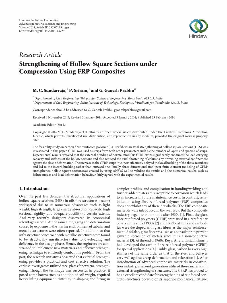
Figure 4: Failure mode of control column.
Figure 5: Failure mode of column HS-50-20-T1(1).
and in-service properties. However, research related to CFRPapplications to steel structures has started quite recently andthere are still few applications in practice due to uncertaintiesconcerning the long term behaviour of these applications andthe bonding between the composite materials and steel.
One of the first known studies on this topic that involvedthe use of CFRP laminates to repair steel structures wasconducted by Sen and Liby [5]. Six composite beams weretested under four-point bending setup. An epoxy adhesivewas used to wrap the CFRP laminates in the tension flange ofthe steel beam in different configurations. High strength steelbolts were also used in an attempt to increase the load transferto the CFRP laminates Test results indicated that moremodest improvement in the elastic response was required,even though significant ultimate strength was gained.
In another investigation, Jiao and Zhao [6] studied theperformance of butt-welded very high strength (VHS) steel
tubes strengthened with CFRP fabrics under axial tension.Three types of epoxy resins with different lap shear strengthswere used. Three kinds of failure modes such as adhesivefailure, fibre tear, and mixed failure were observed. Theabove investigation concluded that a significant strengthcan be achieved using CFRP-epoxy-strengthening techniqueand they also recommended a suitable epoxy adhesive forstrengthening of VHS steel tubes.
Photiou et al. [7] investigated the effectiveness of anultrahigh modulus and high modulus CFRP prepreg instrengthening the artificially degraded steel beam of rectan-gular cross-section under four-point loading by using twodifferent wrapping configurations. The beam containing theultrahigh modulus CFRP failed when the ultimate strain ofthe carbon fibre reached the pure moment region. In addi-tion, the failure load exceeded the plastic collapse load of theundamaged beam.The beams strengthened by using the high

4 Advances in Materials Science and Engineering
Figure 6: Failure mode of column HS-50-20-T2(2).
Figure 7: Failure mode of column HS-50-20-T3(2).
modulus CFRP exhibited ductile response leading to veryhigh deflections even after higher ultimate load was reached.
Seica and Packer [8] investigated the FRP materials forthe rehabilitation of tubular steel structures for underwaterapplications. Six tubes were wrapped with CFRP compos-ites. Two specimens were prepared under in-air conditionsand remaining four specimens were under seawater-curingconditions. The test results shown that the ultimate strengthof the tubes wrapped under in-air and seawater-curingconditions have 16–27% and 8–21% more than that of baresteel beam, respectively.
Tao et al. [9] presented the results of axial compressionand bending tests of fire-damaged concrete-filled steel tubes(CFST) repaired using unidirectional CFRP composites. Bothcircular and square specimens were tested to investigate the
repair effects of CFRP composites on them. The test resultsshowed that the load-carrying capacity and the longitudinalstiffness of CFRP-repaired CFST stub columns increasedwhile their ductility decreased with the increasing number ofCFRP layers. And also it was recommended that appropriaterepair measures should be taken in repairing severely fire-damaged CFST beams or those members subjected to com-paratively large bending moments.
In another study, Tao and Han [10] repaired the fire-exposed CFST beam columns by unidirectional CFRP com-posites. The test results revealed that the fibre jacketsenhanced the load-bearing capacity to some extent, while theinfluence of CFRP repair on stiffness was not apparent.
Elchalakani and Fernando [11] studied the plasticmechanism analysis of unstiffened steel I-section beams
Advances in Materials Science and Engineering 5
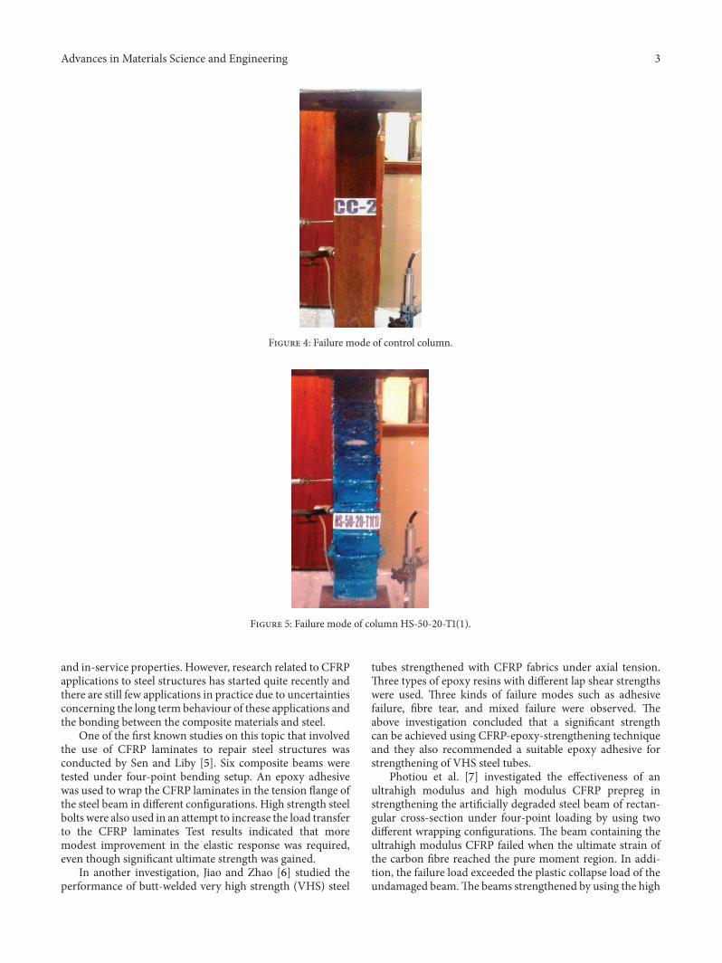
Figure 8: Failure mode of column HS-50-30-T1(1).
Figure 9: Failure mode of column HS-50-30-T2(1).
strengthened with CFRP composites. The CFRP plates wereadded with the specimens on the tension flange and withsome specimens on both compression and tension flangesand some were bonded onto the whole section including theweb. The results showed that the strength enhanced was by32% for the specimens strengthened on both compressionand tension flanges whereas it was by 15% in the case ofspecimens on tension flange only.
Recently, Narmashiri et al. [12] conducted both exper-imental and numerical investigations on the structuralbehaviour of steel I-beams flexurally strengthened by CFRPstrips. Twelve beams were strengthened by using differenttypes and dimensions of CFRP strips. Four types of failuremodes were observed and their occurrences and sequencesare varied on the strengthening schedule.
Kadhim [13] numerically investigated the behavior ofI-beam strengthened with CFRP plate and the effect of
strengthening length. The load-deflection response curveswere predicted using finite element analysis (FEA) and werecompared with experimental data. The analytical resultsshowed that the length of CFRP plate increased the ultimatestrength of beam when they reached 40% and 60% of spanlength in sagging and hogging regions, respectively.
Wu et al. [14] performed a series of experiments toevaluate the bond characteristics between ultrahigh modulus(UHM) CFRP laminate and steel by double strap joints.Different adhesives were used in order to compare their effec-tiveness when used for bonding UHM CFRP laminate withsteel. Theoretical models were employed for the predictionof bond strength and effective bond length. The simulationresults agreedwell with experimentation under ultimate load,load extension curves, and bond-slip relationships.
Al-Zubaidy et al. [15] examined the bond characteristicsbetween CFRP fabrics and steel plate joints under impact
6 Advances in Materials Science and Engineering
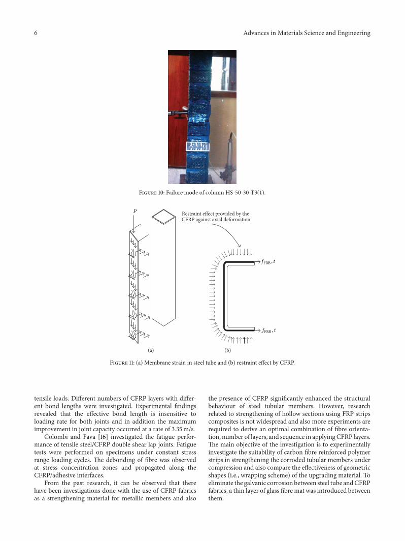
Figure 10: Failure mode of column HS-50-30-T3(1).
P
(a)
Restraint effect provided by theCFRP against axial deformation
fFRB , t
fFRB , t
(b)
Figure 11: (a) Membrane strain in steel tube and (b) restraint effect by CFRP.
tensile loads. Different numbers of CFRP layers with differ-ent bond lengths were investigated. Experimental findingsrevealed that the effective bond length is insensitive toloading rate for both joints and in addition the maximumimprovement in joint capacity occurred at a rate of 3.35m/s.
Colombi and Fava [16] investigated the fatigue perfor-mance of tensile steel/CFRP double shear lap joints. Fatiguetests were performed on specimens under constant stressrange loading cycles. The debonding of fibre was observedat stress concentration zones and propagated along theCFRP/adhesive interfaces.
From the past research, it can be observed that therehave been investigations done with the use of CFRP fabricsas a strengthening material for metallic members and also
the presence of CFRP significantly enhanced the structuralbehaviour of steel tubular members. However, researchrelated to strengthening of hollow sections using FRP stripscomposites is not widespread and also more experiments arerequired to derive an optimal combination of fibre orienta-tion, number of layers, and sequence in applyingCFRP layers.The main objective of the investigation is to experimentallyinvestigate the suitability of carbon fibre reinforced polymerstrips in strengthening the corroded tubular members undercompression and also compare the effectiveness of geometricshapes (i.e., wrapping scheme) of the upgrading material. Toeliminate the galvanic corrosion between steel tube andCFRPfabrics, a thin layer of glass fibre mat was introduced betweenthem.

Advances in Materials Science and Engineering 7
0
10
20
30
40
50
60
70
80
90
100
0 0.005 0.01 0.015 0.02 0.025Axial strain
CC2 HS-50-20-T2(1)HS-50-20-T1(1) HS-50-20-T3(1)
Axi
al st
ress
(N/m
m2)
Figure 12: Axial stress-strain behaviour of columns HS-50-20—comparison.
0
10
20
30
40
50
60
70
80
90
100
0 0.005 0.01 0.015 0.02 0.025Axial strain
CC2 HS-50-30-T1(1)HS-50-30-T2(1) HS-50-30-T3(1)
Axi
al st
ress
(N/m
m2)
Figure 13: Axial stress-strain behaviour of columns HS-50-30—comparison.
2. Materials
2.1. Carbon Fibre. The unidirectional carbon fibre calledMBrace 240 fabricated by BASF India Inc was used in thisstudy. It is a low modulus CFRP fibre having modulus ofelasticity of 240 kN/mm2 and the tensile strength of 3800N/mm2.The thickness andwidth of the fibrewere 0.234mmand
600mm, respectively. It is a fabric type and can be tailored toany desired shape.
2.2. Adhesive. The MBrace saturant supplied by BASF IndiaInc was used in this study to get sufficient bonding betweensteel tube and carbon fibre. It is a two-part system, a resin anda hardener, and the mixing ratio was 100 : 40 (B :H).

8 Advances in Materials Science and Engineering
CC2HS-50-30-T1(1)
HS-50-20-T2(1) HS-50-30-T2(1)HS-50-20-T1(1) HS-50-30-T3(1)HS-50-20-T3(1)
0
10
20
30
40
50
60
70
80
90
100
Axi
al st
ress
(N/m
m2)
0 0.005 0.01 0.015 0.02 0.025Axial strain
Figure 14: Axial stress-strain behaviours of all columns—comparison.
0
2
4
6
8
10
CC2 HS-50-20-T1(2) HS-50-20-T2(2) HS-50-20-T3(1)Designation of columns
Axi
al d
efor
mat
ion
(mm
)
Figure 15: Axial deformation for columns HS-50-20—comparison.
0
2
4
6
8
10
Axi
al d
efor
mat
ion
(mm
)
CC2 HS-50-30-T1(2) HS-50-30-T2(1) HS-50-30-T3(2)Designation of columns
Figure 16: Axial deformation for columns HS-50-30—comparison.
Advances in Materials Science and Engineering 9
0
2
4
6
8
10
Axi
al d
efor
mat
ion
(mm
)One layer Two layers Three layers
Number of FRP layers
20mm spacing30mm spacing
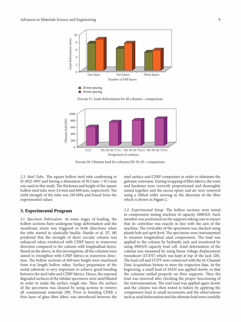
Figure 17: Axial deformation for all columns—comparison.
0
200
400
600
800
1000
Ulti
mat
e loa
d (k
N)
CC2 HS-50-20-T1(1) HS-50-20-T2(1) HS-50-20-T3(1)Designation of columns
Figure 18: Ultimate load for columns HS-50-20—comparison.
2.3. Steel Tube. The square hollow steel tube confirming toIS 4923-1997 and having a dimension of 91.5mm × 91.5mmwas used in this study.The thickness and height of the squarehollow steel tube were 3.6mm and 600mm, respectively.Theyield strength of the tube was 249MPa and found from theexperimental values.
3. Experimental Program
3.1. Specimen Fabrication. At some stages of loading, thehollow sections have undergone large deformation and themembrane strain was triggered in both directions whenthe tube started to elastically buckle. Haedir et al. [17, 18]predicted that the strength of short circular column wasenhanced when reinforced with CFRP layers in transversedirection compared to the column with longitudinal layers.Based on the above, in this investigation, all the columnswereaimed to strengthen with CFRP fabrics in transverse direc-tion. The hollow sections of 600mm height were machinedfrom 6m length hollow tubes. Surface preparation of themetal substrate is very important to achieve good bondingbetween the steel tube and CFRP fabrics. Hence, the exposeddegraded surfaces of the tubular specimens were sand blastedin order to make the surface rough one. Then the surfaceof the specimens was cleaned by using acetone to removeall contaminant materials [19]. Prior to bonding CFRP, athin layer of glass fibre fabric was introduced between the
steel surface and CFRP composites in order to eliminate thegalvanic corrosion. Duringwrapping of fibre fabrics, the resinand hardener were correctly proportioned and thoroughlymixed together and the excess epoxy and air were removedusing a ribbed roller moving in the direction of the fibrewhich is shown in Figure 2.
3.2. Experimental Setup. The hollow sections were testedin compression testing machine of capacity 2000 kN. Eachmember was positioned on the supports taking care to ensurethat its centreline was exactly in line with the axis of themachine. The verticality of the specimens was checked usingplumb bob and sprit level. The specimens were instrumentedto measure longitudinal axial compression. The load wasapplied to the column by hydraulic jack and monitored byusing 1000 kN capacity load cell. Axial deformation of thecolumn was measured by using linear voltage displacementtransducer (LVDT) which was kept at top of the jack [20].The load cell and LVDT were connected with the 16-ChannelData Acquisition System to store the respective data. At thebeginning, a small load of 20 kN was applied slowly, so thatthe columns settled properly on thier supports. Then theload was removed after checking the proper functioning ofthe instrumentation. The trial load was applied again slowlyand the column was then tested to failure by applying thecompressive load in small increments and the observationssuch as axial deformation and the ultimate loadwere carefully
10 Advances in Materials Science and Engineering
0
200
400
600
800
1000
Ulti
mat
e loa
d (k
N)
CC1 HS-50-30-T1(3) HS-50-30-T2(1) HS-50-30-T3(1)Designation of columns
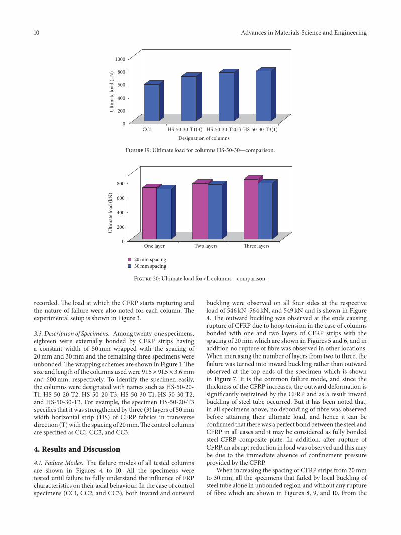
Figure 19: Ultimate load for columns HS-50-30—comparison.
0
200
400
600
800
Ulti
mat
e loa
d (k
N)
One layer Two layers Three layers
20mm spacing30mm spacing
Figure 20: Ultimate load for all columns—comparison.
recorded. The load at which the CFRP starts rupturing andthe nature of failure were also noted for each column. Theexperimental setup is shown in Figure 3.
3.3. Description of Specimens. Among twenty-one specimens,eighteen were externally bonded by CFRP strips havinga constant width of 50mm wrapped with the spacing of20mm and 30mm and the remaining three specimens wereunbonded.The wrapping schemes are shown in Figure 1.Thesize and length of the columns used were 91.5 × 91.5 × 3.6mmand 600mm, respectively. To identify the specimen easily,the columns were designated with names such as HS-50-20-T1, HS-50-20-T2, HS-50-20-T3, HS-50-30-T1, HS-50-30-T2,and HS-50-30-T3. For example, the specimen HS-50-20-T3specifies that it was strengthened by three (3) layers of 50mmwidth horizontal strip (HS) of CFRP fabrics in transversedirection (T)with the spacing of 20mm.The control columnsare specified as CC1, CC2, and CC3.
4. Results and Discussion
4.1. Failure Modes. The failure modes of all tested columnsare shown in Figures 4 to 10. All the specimens weretested until failure to fully understand the influence of FRPcharacteristics on their axial behaviour. In the case of controlspecimens (CC1, CC2, and CC3), both inward and outward
buckling were observed on all four sides at the respectiveload of 546 kN, 564 kN, and 549 kN and is shown in Figure4. The outward buckling was observed at the ends causingrupture of CFRP due to hoop tension in the case of columnsbonded with one and two layers of CFRP strips with thespacing of 20mmwhich are shown in Figures 5 and 6, and inaddition no rupture of fibre was observed in other locations.When increasing the number of layers from two to three, thefailure was turned into inward buckling rather than outwardobserved at the top ends of the specimen which is shownin Figure 7. It is the common failure mode, and since thethickness of the CFRP increases, the outward deformation issignificantly restrained by the CFRP and as a result inwardbuckling of steel tube occurred. But it has been noted that,in all specimens above, no debonding of fibre was observedbefore attaining their ultimate load, and hence it can beconfirmed that there was a perfect bond between the steel andCFRP in all cases and it may be considered as fully bondedsteel-CFRP composite plate. In addition, after rupture ofCFRP, an abrupt reduction in load was observed and thismaybe due to the immediate absence of confinement pressureprovided by the CFRP.
When increasing the spacing of CFRP strips from 20mmto 30mm, all the specimens that failed by local buckling ofsteel tube alone in unbonded region and without any ruptureof fibre which are shown in Figures 8, 9, and 10. From the

Advances in Materials Science and Engineering 11
Element coordinate system
Y
Z
X
K
N
L
J
I
M
P
4
5
6
3
Surface coordinate system
y
x
y
y
x
x
z
1
2(shown for KEYOPT (4) = 1)
O
Figure 21: Solid45 element 3D solid (ANSYS12.0).
8975778065845388
MNMX
419329971802606.351 10171 11366
ZY
X
Figure 22: Typical computed deformed shapes of CC.
above observations, it can be noted that when increasingthe spacing of CFRP strips, the unbonded area will becomemore and it was subjected to maximum strain during loadingand consequently buckling of steel tube occurred in theunwrapped zone due to the absence of confinement pressureprovided by the CFRP composites.
4.2. Axial Stress-Strain Behavior. The square hollow steeltube may be considered as stiffened plates and by assumingthat their both longitudinal edges are fixed, the slendernessratio of the plate calculated by the following equation (1) isproposed by Seica and Packer [8]:
𝜆 = √𝑓𝑦
𝑓𝑐𝑟
,
𝑓𝑐𝑟=𝑘𝜋2𝐸
12 (1 − 𝜐2)(𝑡
𝑏)2
,
(1)
where𝑓𝑦and𝑓𝑐𝑟(the stress at which amaterial failed by crip-
pling/buckling) are the yield stress and ultimate elastic buck-ling stress respectively. The yield stress (𝑓
𝑦) can be defined
as the stress at which a material begins to deform plasticallywhich was obtained from the steel coupon test. The elasticbuckling stress, can be defined as the stress at whichmaterialsfailed by crippling/buckling, which was obtained form theequation proposed by Seica and Packer [8]. 𝑡 and 𝑏 are thethickness and width of the plate and 𝜐 and 𝐸 are the poisonsratio and Young’s modulus of the plate. For stiffened element,the buckling coefficient of the plate was taken as 4.0 [8].
Table 1 shows the slenderness value, maximum axialdeformation, average experimental buckling stress, andpercentage of enhancement in axial deformation control ofthe strengthened columns compared to CC2. From Figures12 to 17, it was observed that external bonding of CFRPfabrics effectively delayed the local buckling of the steel tubeand also reduced the axial shortening by providing externalconfinement against the elastic deformation which is shownin Figure 11. At some stages in loading, the plates in themembers have undergone large deformation and the mem-brane strain was triggered in both directions, which is shownin Figure 11(a). In the meantime, CFRP that lies in the outerlimits started to resist lateral and axial strains by providing

12 Advances in Materials Science and Engineering
5.6214.8184.0153.212
MN
MX
2.4091.606.8030690 6.425 7.228
ZYX
Figure 23: Typical computed deformed shapes of HS-50-20-T1.
6.1335.2574.3813.505
MN
MX
2.6281.752.8761590 7.009 7.885
ZYX
Figure 24: Typical computed deformed shapes of HS-50-20-T2.
confinement pressure as they were subjected to tension in thehoop direction as shown in Figure 11(b).That confining pres-sure exerted by the CFRP strips composites against the axialdeformation can be called the restrained effect. Compared tocontrol specimens, the columns HS-50-20-T1(1), HS-50-20-T2(1), and HS-50-20-T3(1) enhanced their restraining effectby 68.68%, 116.88%, and 163.40% respectively, and significantfall in curve was observed at the peak stage due to suddenrupture of CFRP. The addition of number of layers thatprovides further enhancement in buckling stress is shownin Figures 12 and 15. From the above observations, it can beseen that bonding of CFRP fabrics increases the thicknessof the steel tube and decreases the slenderness value of thecomposite plate and as a result, the elastic buckling stress ofthe steel tube increased. In addition to that the enhancementin buckling stress due to addition of layers was notproportional.The above nonlinearity in buckling stress whenincreasing the number of fibre layers may be attributed tocrushing of resin lying in-between the fibres. When the resinstarted to crush, a sudden drop in substantial load transferoccurred and as a result, nonlinearity in axial deformationcontrol was observed. At the respective failure load ofspecimens such as HS-50-20-T1(1) and HS-50-20-T2(1), theaxial deformation of a specimen HS-50-20-T3(1) observedwas 4.57mm and 5.13mm, respectively, and furthermorethis deflection was 25% to 80% lesser than that of specimens
HS-50-20-T1(1) and HS-50-20-T2(1) which is shown inFigure 15. When increasing the spacing of FRP strips from20mm to 30mm, the above similar behaviour was observedin those columns; besides, the buckling stresses of thecolumns were reduced. The enhancements in restrainingeffect against axial deformation provided by the specimensHS-50-30-T1(1), HS-50-30-T2(1), and HS-50-30-T3(1)were 53.21%, 92.39%, and 125.67%, respectively, comparedto the column CC2 which is shown in Figures 13 and 16.The experimental stress-strain behaviour of all columns ispresented in Figure 14. The column HS-50-30-T1(2) that hashigher axial deformation of 9.12mm compared to columnHS-50-20-T1(2) which has an axial deformation of 7.45mmis shown in Figure 17. And also, the column HS-50-20-T2(2) tends to have more capability of controlling axialdeformation compared to column HS-50-30-T2(1). Figure17 also illustrates that the column HS-50-30-T3(1) has moreaxial deformation (7.02mm) than of columnHS-50-20-T3(1)(6.12mm) which is 14.7% less than HS-50-20-T3(1). This isa result of the fact that, when increasing the spacing of fibrestrips, the unbonded area will become more and as a result,reduction in restraint provided by the CFRP strips againstthe axial deformation was observed.
4.3. Load Carrying Capacity. The experimental ultimatestrength and the percentage of enhancement in it resulting

Advances in Materials Science and Engineering 13
4000300020001000
MN
MX
500200129.865 8000 10000
ZYX
Figure 25: Typical computed deformed shapes of HS-50-20-T3.
5450471139713231
MN
MX
249217521012272.574 6190 6930
Y X
Figure 26: Typical computed deformed shapes of HS-50-30-T1.
from the bonding of CFRP strips with various spacing arepresented in Table 1.The load carrying capacity of the columncan be defined as the column ability to resist the axial load.The graphical representation of enhancement in ultimatestrength against number of layers is given in Figures 18 to20. From that, it is confirmed that significant enhancementin ultimate strength can be achieved with the application ofCFRP strips, especially up to 44.32% more than that of baresteel tube.The load atwhich the column failedwas consideredas a maximum axial force or ultimate strength. Compared tocontrol column (CC1), the specimens HS-50-20-T1(1), HS-50-20-T2(1), and HS-50-20-T3(1) enhanced their axial loadcarrying capacity by 25.71%, 35.46%, and 44.32% as shownin Figure 18. In similar manner, the columns wrapped with30mm spacing of CFRP strips such as HS-50-30-T1(3), HS-50-30-T2(1), and HS-50-30-T3(1) have 22.51%, 32.8%, and36.52%, respectively, more load carrying capacity than thatof control column as shown in Figure 19. This informs thatexternal bonding of CFRP strips provided sufficient restrain-ing effect against deformation and also delayed the localbuckling of steel tube and as a result the ultimate strengthcapacity was increased. From Figures 18 and 19, it is clearedthat increase in number ofCFRP layers enhanced the ultimatestrength capacity of the steel tube; however, the enhancement
in ultimate strength due to addition of layers was notproportional. As said earlier, this is a result of the fact that byincreasing CFRP layers, the composite plate thickness is alsoincreased and as a result, the elastic buckling stress/ultimatestrength of the steel tube increased. The column HS-50-20-T3(1) enhanced its axial load carrying capacity by 17.63%and 8.9% more than the columns HS-50-20-T1(2) and HS-50-20-T2(2), respectively. Similarly, the column HS-50-30-T3(1) enhanced its load carrying capacity by 12.9% and4.19% compared to columns HS-50-30-T1(2) and HS-50-30-T2(3), respectively. From Figure 20, it is also confirmedthat the columns strengthened by CFRP strips with smallerspacing havemore ultimate strength, and increase in ultimatestrength mainly depends on the proper designed spacing ofCFRP strips.When compared to columnHS-50-30-T1(3), thecolumn HS-50-20-T1(2) has more load carrying capacity andalso the column HS-50-20-T2(1) enhanced its load carryingcapacity by 2% compared with the column HS-50-30-T2(1).Figure 20 also illustrates that the columnHS-50-20-T3(1) hasmore axial load carrying capacity (814 kN) than column HS-50-30-T3(1) (770 kN) and which is 5.71% more than HS-50-30-T3(1). From the above observations, it can be suggestedthat more benefit can be achieved by the bonding of CFRPstrips having a spacing of 20mm.
14 Advances in Materials Science and Engineering
2.1821.8181.4541.091
MX
MN
.72719.3635990 2.545 3.272
Y
Z
X
2.909
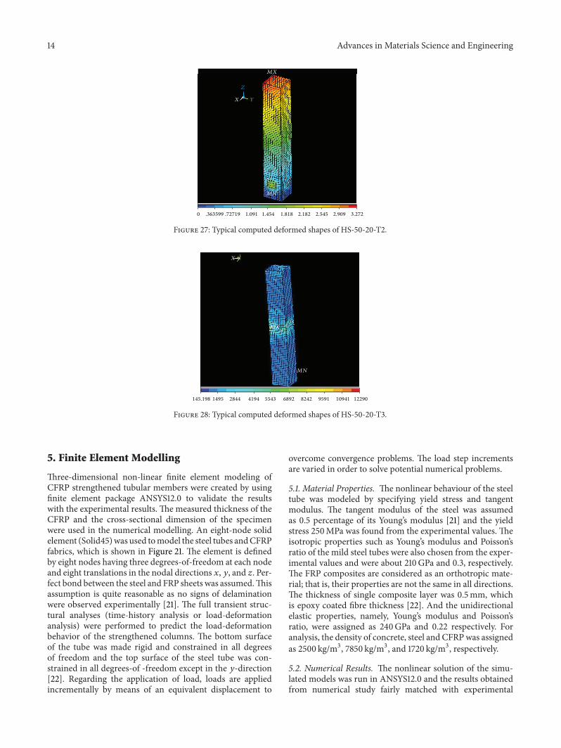
Figure 27: Typical computed deformed shapes of HS-50-20-T2.
8242689255434194
MX
MN
1495 2844145.198 9591 12290
YX
10941
Figure 28: Typical computed deformed shapes of HS-50-20-T3.
5. Finite Element Modelling
Three-dimensional non-linear finite element modeling ofCFRP strengthened tubular members were created by usingfinite element package ANSYS12.0 to validate the resultswith the experimental results. The measured thickness of theCFRP and the cross-sectional dimension of the specimenwere used in the numerical modelling. An eight-node solidelement (Solid45)was used tomodel the steel tubes andCFRPfabrics, which is shown in Figure 21. The element is definedby eight nodes having three degrees-of-freedom at each nodeand eight translations in the nodal directions 𝑥, 𝑦, and 𝑧. Per-fect bond between the steel and FRP sheets was assumed.Thisassumption is quite reasonable as no signs of delaminationwere observed experimentally [21]. The full transient struc-tural analyses (time-history analysis or load-deformationanalysis) were performed to predict the load-deformationbehavior of the strengthened columns. The bottom surfaceof the tube was made rigid and constrained in all degreesof freedom and the top surface of the steel tube was con-strained in all degrees-of -freedom except in the 𝑦-direction[22]. Regarding the application of load, loads are appliedincrementally by means of an equivalent displacement to
overcome convergence problems. The load step incrementsare varied in order to solve potential numerical problems.
5.1. Material Properties. The nonlinear behaviour of the steeltube was modeled by specifying yield stress and tangentmodulus. The tangent modulus of the steel was assumedas 0.5 percentage of its Young’s modulus [21] and the yieldstress 250MPa was found from the experimental values. Theisotropic properties such as Young’s modulus and Poisson’sratio of the mild steel tubes were also chosen from the exper-imental values and were about 210GPa and 0.3, respectively.The FRP composites are considered as an orthotropic mate-rial; that is, their properties are not the same in all directions.The thickness of single composite layer was 0.5mm, whichis epoxy coated fibre thickness [22]. And the unidirectionalelastic properties, namely, Young’s modulus and Poisson’sratio, were assigned as 240GPa and 0.22 respectively. Foranalysis, the density of concrete, steel and CFRPwas assignedas 2500 kg/m3, 7850 kg/m3, and 1720 kg/m3, respectively.
5.2. Numerical Results. The nonlinear solution of the simu-lated models was run in ANSYS12.0 and the results obtainedfrom numerical study fairly matched with experimental

Advances in Materials Science and Engineering 15
0
10
20
30
40
50
60
70
80
90
100
0 0.005 0.01 0.015 0.02 0.025Axial strain
Experimental-CC2FEM-(ANSYS)
Axi
al st
ress
(N/m
m2)
Figure 29: Comparison of experimental and computed axial stress-strain behaviours of control columns.
0
10
20
30
40
50
60
70
80
90
100
0 0.005 0.01 0.015 0.02 0.025Axial strain
FEM-HS-50-20-T1(1)HS-50-20-T1(1)
Axi
al st
ress
(N/m
m2)
Figure 30: Comparison of experimental and computed axial stress-strain behaviours of HS-50-20-T1(1) columns.
study. The deformed shapes of the columns obtained bynumerical simulation fairly agreed with the correspondingexperimental results. In the numerical modeling, the failuremode of column with the spacing of 20mm was ruptureof fibre followed by outward buckling of steel tube whereasthe column with the spacing of 30mm collapsed by localbuckling of steel tube, which is shown in Figures 22, 23, 24,
25, 26, 27, and 28. The above same type of failure modewas observed during experimentation. Computational load-deformation behavior of CFRP strengthened columns werealso compared with experimental results and are representedin Figures 29 to 35. The load deformation curve obtained bynumerical simulation for all strengthened columns exhibitedlinear elastic behavior until it reached the failure load of

16 Advances in Materials Science and Engineering
0
10
20
30
40
50
60
70
80
90
100
0 0.005 0.01 0.015 0.02 0.025Axial strain
FEM-HS-50-20-T2(1)HS-50-20-T2(1)
Axi
al st
ress
(N/m
m2)
Figure 31: Comparison of experimental and computed axial stress-strain behaviours of HS-50-20-T2(1) columns.
0
10
20
30
40
50
60
70
80
90
100
0 0.005 0.01 0.015 0.02 0.025Axial strain
HS-50-20-T3(1)FEM-HS-50-20-T3(1)
Axi
al st
ress
(N/m
m2)
Figure 32: Comparison of experimental and computed axial stress-strain behaviours of HS-50-20-T3(1) columns.
control column, followed by inelastic behavior when increas-ing the load. In addition to this, behavior of those had goodagreement with the experimental results. Until it reached theyield point, for all columns, it was found to be 2 to 4mmless in axial deformation in the case of computational graphscompared with the experimental results as shown in Figures29, 30, 31, 32, 33, 34, and 35.Theultimate values obtained fromnumerical simulation fairly agreed with the experimentalresults and in addition the obtained values are 10% to 15%more than that of experimental results.
6. Conclusions
Experimental andnumerical investigations on the behavioursof axially loaded tubular columns strengthened by CFRPstrips with two types of spacing were presented in this paper.The finite element model was created by considering thegeometric and material non linearities and the results weresuccessfully verified against the experimental value. Basedon the experimental and numerical results, the followingconclusions and recommendations are drawn.

Advances in Materials Science and Engineering 17
0
10
20
30
40
50
60
70
80
90
100
0 0.005 0.01 0.015 0.02 0.025Axial strain
HS-50-30-T1(1)FEM-HS-50-30-T1(1)
Axi
al st
ress
(N/m
m2)
Figure 33: Comparison of experimental and computed axial stress-strain behaviours of HS-50-30-T1(1) columns.
0
10
20
30
40
50
60
70
80
90
100
0 0.005 0.01 0.015 0.02 0.025Axial strain
HS-50-30-T2(1)FEM-HS-50-30-T2(1)
Axi
al st
ress
(N/m
m2)
Figure 34: Comparison of experimental and computed axial stress-strain behaviours of HS-50-30-T2(1) columns.
(i) The increase in number of layers turned into fail-ure mode of inward buckling rather than outwardbuckling. It is due to the external restraint effect byCFRP fabrics against outward buckling and as a resultinward buckling of steel tube occurred.
(ii) No debonding of fibre was observed due to perfectbond between steel and fibre.
(iii) The external bonding of CFRP fabrics effectivelydelayed the local buckling of the steel tube and alsoreduced the axial shortening by providing confine-ment against the elastic deformation.
(iv) The enhancements in restraining effect against axialdeformation provided by the specimens such as HS-50-30-T1(1), HS-50-30-T2(1), and HS-50-30-T3(1)were observed as 53.21%, 92.39%, and 125.67%,respectively, compared to control column.
(v) The test results revealed that significant enhancementin ultimate strength can be achieved with the appli-cation of CFRP strips, especially up to 44.32% morethan that of bare steel tube.
(vi) Compared to control column (CC1), the specimensHS-50-20-T1(1), HS-50-20-T2(1), andHS-50-20-T3(1)

18 Advances in Materials Science and Engineering
0
10
20
30
40
50
60
70
80
90
100
0 0.005 0.01 0.015 0.02 0.025Axial strain
HS-50-30-T3(1)FEM-HS-50-30-T3(1)
Axi
al st
ress
(N/m
m2)
Figure 35: Comparison of experimental and computed axial stress-strain behaviours of HS-50-30-T3(1) columns.
Table 1: Maximum deformation, percentage of reduction in deformation, and increase in load carrying capacity.
Designation ofcolumns
Failure load(kN)
Maximum axialdeformation
(mm)
% of reduction inaxial deformationcompared to CC2
(kN)
% of increase in axialload carrying capacity
(kN)
Slendernessvalue (𝜆)
CC1 546 8.29 — —0.46CC2 564 8.35 — —
CC3 549 8.5 — —HS-50-20-T1(1) 709 7.91 68.68 25.71
0.35HS-50-20-T1(2) 692 7.45 65.34 22.69HS-50-20-T1(3) 697 7.57 67 23.58HS-50-20-T2(1) 764 7.46 116.88 35.46
0.31HS-50-20-T2(2) 747 6.93 111.98 32.44HS-50-20-T2(3) 753 7.07 114.87 33.51HS-50-20-T3(1) 814 6.12 163.40 44.32
0.28HS-50-20-T3(2) 803 6.02 161.56 42.37HS-50-20-T3(3) 798 5.94 159.45 41.48HS-50-30-T1(1) 690 9.27 53.21 22.34
0.35HS-50-30-T1(2) 682 9.12 50.96 20.92HS-50-30-T1(3) 691 9.23 51.67 22.51HS-50-30-T2(1) 749 8.18 92.39 32.8
0.31HS-50-30-T2(2) 741 8.02 91.43 31.38HS-50-30-T2(3) 739 7.98 89.6 31.03HS-50-30-T3(1) 770 7.02 125.67 36.52
0.28HS-50-30-T3(2) 764 7.03 123.7 35.46HS-50-30-T3(3) 761 6.94 122.34 34.92

Advances in Materials Science and Engineering 19
enhanced their axial load carrying capacity by 25.71%,35.46%, and 44.32%.
(vii) The external bonding of CFRP fabrics increases thethickness of the steel tube and decreases the slender-ness value of the composite plate and as a result, theelastic buckling stress of the steel tube was increased.
(viii) The numerical results such as failure modes and loaddeformation behaviour fairly agreed with the experi-mental results. And also, the deformed shapes of thetubular columns obtained by numerical simulationfairly agreed with the corresponding experimentalresults.
(ix) It is suggested that external strengthening of tubularcolumns using normalmodulus CFRP strips is a quiteeffective technique in increasing the load carryingcapacity and stiffness of the tubular sections.
Conflict of Interests
The authors declare that there is no conflict of interestsregarding the publication of this paper.
References
[1] G. L. Balazs and A. Borosnyoi, “Long-term behavior of FRP,”in Proceedings of the International Workshop on Composites inConstruction: A Reality, pp. 84–91, American Society of CivilEngineers, Capri, Italy, 2001.
[2] L. Hollaway, Polymer Composites for Civil and Structural Engi-neering, Blackie Academic and Professional, London, UK, 1993.
[3] S. Peters, Handbook of Composites, Chapman & Hall, London,UK, 2nd edition, 1998.
[4] L. Hollaway, Handbook of Polymer Composites for Engineers,Woodhead Publishing, Cambridge, UK, 1st edition, 1994.
[5] R. Sen and L. Liby, “Repair of steel composite bridge sectionsusingCFRP laminates,” USDepartment of TransportationCon-tract B-7932, University of South Florida, Tampa, Fla, USA,1994.
[6] H. Jiao and X.-L. Zhao, “CFRP strengthened butt-welded veryhigh strength (VHS) circular steel tubes,” Thin-Walled Struc-tures, vol. 42, no. 7, pp. 963–978, 2004.
[7] N. K. Photiou, L. C. Hollaway, and M. K. Chryssanthopoulos,“Strengthening of an artificially degraded steel beam utilisinga carbon/glass composite system,” Construction and BuildingMaterials, vol. 20, no. 1-2, pp. 11–21, 2006.
[8] M. V. Seica and J. A. Packer, “FRP materials for the rehabili-tation of tubular steel structures, for underwater applications,”Composite Structures, vol. 80, no. 3, pp. 440–450, 2007.
[9] Z. Tao, L.-H. Han, and L.-L. Wang, “Compressive and flexuralbehaviour of CFRP-repaired concrete-filled steel tubes afterexposure to fire,” Journal of Constructional Steel Research, vol.63, no. 8, pp. 1116–1126, 2007.
[10] Z. Tao and L.-H. Han, “Behaviour of fire-exposed concrete-filled steel tubular beam columns repaired with CFRP wraps,”Thin-Walled Structures, vol. 45, no. 1, pp. 63–76, 2007.
[11] M. Elchalakani and D. Fernando, “Plastic mechanism analysisof unstiffened steel I-section beams strengthened with CFRPunder 3-point bending,”Thin-Walled Structures, vol. 53, pp. 58–71, 2012.
[12] K. Narmashiri, N. H. R. Sulong, and M. Z. Jumaat, “Failureanalysis and structural behaviour of CFRP strengthened steelI-beams,” Construction and Building Materials, vol. 30, pp. 1–9,2012.
[13] M. M. A. Kadhim, “Effect of CFRP plate length strengtheningcontinuous steel beam,” Construction and Building Materials,vol. 28, no. 1, pp. 648–652, 2012.
[14] C. Wu, X. Zhao, W. H. Duan, and R. Al-Mahaidi, “Bond cha-racteristics between ultra high modulus CFRP laminates andsteel,”Thin-Walled Structures, vol. 51, pp. 147–157, 2012.
[15] H. Al-Zubaidy, R. Al-Mahaidi, and X.-L. Zhao, “Experimentalinvestigation of bond characteristics between CFRP fabricsand steel plate joints under impact tensile loads,” CompositeStructures, vol. 94, no. 2, pp. 510–518, 2012.
[16] P. Colombi and G. Fava, “Fatigue behaviour of tensile steel/CFRP joints,”Composite Structures, vol. 94, no. 8, pp. 2407–2417,2012.
[17] J. Haedir, M. R. Bambach, X. L. Zhao, and R. Grzebieta, “Bend-ing strength of CFRP-strengthened circular hollow steel sec-tions,” in Proceedings of the 3rd International Conference on FRPComposites in Civil Engineering (CICE ’06), Miami, Fla, USA,2006.
[18] M. C. Sundarraja and G. G. Prabhu, “Behaviour of CFSTmembers under compression externally reinforced by CFRPcomposites,” Journal of Civil Engineering and Management, vol.19, no. 2, pp. 184–195, 2013.
[19] J. Haedir, M. R. Bambach, X.-L. Zhao, and R. H. Grzebieta,“Behaviour of thin-walled CHS beams reinforced by CFRPsheets,” in Proceedings of the 4th International Structural Engi-neering and Construction Conference (ISEC4 ’07), pp. 701–706,Melbourne, Australia, September 2007.
[20] X. Qu, Z. Chen, and G. Sun, “Experimental study of rectangularCFST columns subjected to eccentric loading,” Thin-WalledStructures, vol. 64, pp. 83–93, 2013.
[21] A. Shaat and A. Fam, “Finite element analysis of slender HSScolumns strengthened with high modulus composites,” Steeland Composite Structures, vol. 7, no. 1, pp. 19–34, 2007.
[22] Z. Tao, Z.-B. Wang, and Q. Yu, “Finite element modelling ofconcrete-filled steel stub columns under axial compression,”Journal of Constructional Steel Research, vol. 89, pp. 121–131, 2013.

Submit your manuscripts athttp://www.hindawi.com
ScientificaHindawi Publishing Corporationhttp://www.hindawi.com Volume 2014
CorrosionInternational Journal of
Hindawi Publishing Corporationhttp://www.hindawi.com Volume 2014
Polymer ScienceInternational Journal of
Hindawi Publishing Corporationhttp://www.hindawi.com Volume 2014
Hindawi Publishing Corporationhttp://www.hindawi.com Volume 2014
CeramicsJournal of
Hindawi Publishing Corporationhttp://www.hindawi.com Volume 2014
CompositesJournal of
NanoparticlesJournal of
Hindawi Publishing Corporationhttp://www.hindawi.com Volume 2014
Hindawi Publishing Corporationhttp://www.hindawi.com Volume 2014
International Journal of
Biomaterials
Hindawi Publishing Corporationhttp://www.hindawi.com Volume 2014
NanoscienceJournal of
TextilesHindawi Publishing Corporation http://www.hindawi.com Volume 2014
Journal of
NanotechnologyHindawi Publishing Corporationhttp://www.hindawi.com Volume 2014
Journal of
CrystallographyJournal of
Hindawi Publishing Corporationhttp://www.hindawi.com Volume 2014
The Scientific World JournalHindawi Publishing Corporation http://www.hindawi.com Volume 2014
Hindawi Publishing Corporationhttp://www.hindawi.com Volume 2014
CoatingsJournal of
Advances in
Materials Science and EngineeringHindawi Publishing Corporationhttp://www.hindawi.com Volume 2014
Smart Materials Research
Hindawi Publishing Corporationhttp://www.hindawi.com Volume 2014
Hindawi Publishing Corporationhttp://www.hindawi.com Volume 2014
MetallurgyJournal of
Hindawi Publishing Corporationhttp://www.hindawi.com Volume 2014
BioMed Research International
MaterialsJournal of
Hindawi Publishing Corporationhttp://www.hindawi.com Volume 2014
Nano
materials
Hindawi Publishing Corporationhttp://www.hindawi.com Volume 2014
Journal ofNanomaterials