Embed Size (px)
Citation preview

Lee et al. Visualization in Engineering 2014, 2:7http://www.viejournal.com/content/2/1/7
RESEARCH ARTICLE Open Access
Automatic design algorithms for securing theground contact stability of mobile cranesDonghoon Lee1, Jun Young Park1, Jongkwan Ho2 and Sunkuk Kim1*
Abstract
Background: Mobile cranes overturn due to excessive lifting, heavy wind, or when appropriate ground contactpressure is not secured. Such accidents can be prevented by reviewing the force conveyed from the outrigger tothe ground upon lifting, as well as the soil bearing force. The stability review of mobile crane overturn is classifiedinto the following stages: reviewing lifting conditions, mobile crane selection and reviewing ground contactstability. However, a precise review of ground contact stability requires expertise and is extremely time-consuming.Thus, this study develops automatic design algorithms for securing the ground stability of mobile cranes for easyand quick stability reviews.
Methods: The stability review method and the algorithm models are created in connection with the proposedconceptual process. The algorithms proposed in this study conduct simulations for all possible candidate cases,save the results in a database, review practical alternatives, and select the solution that minimizes cost. To verify theeffectiveness of the automatic design model, a case project was selected and the algorithm was applied assumingseveral conditions.
Results: Developed algorithms can select candidate cranes according to lifting conditions and design platesthrough simulations easily and quickly, and design components required for ground contact plate design arecollected to build the database that allows easier and quicker stability review.
Conclusion: The algorithms proposed in this study conduct simulations for all possible candidate cases, save theresults in a database, review practical alternatives, and select the solution that minimizes cost. Developed processesare useful for analyzing correlations of mobile crane performance, ground contact and soil bearing forcereinforcement designs and so forth, and for systematically selecting optimal mobile cranes.
Keywords: Mobile crane; Stability; Lifting plan; Ground contact pressure; Automatic design model
BackgroundMany crane accidents occur globally, including the over-turn of mobile cranes in Phuket, Thailand and England(The Vertikal Press 2014). As the use of cranes increasesin South Korea, the number of overturn accidents isgradually increasing, and accidents related to mobilecranes account for approximately 61.4% of all crane acci-dents (Kim and Lee 2007). Overturn of mobile cranesoccurs due to excessive lifting, heavy wind, or when ap-propriate ground contact pressure is not secured. Suchaccidents can be minimized by reviewing the force that isconveyed from the outrigger to the ground upon lifting
* Correspondence: [email protected] of Architectural Engineering, Kyung Hee University, 1732Deogyeong-dearo, Giheung-gu, Yongin-si, Gyeonggi-do, KoreaFull list of author information is available at the end of the article
© 2014 Lee et al.; licensee Springer. This is an OAttribution License (http://creativecommons.orin any medium, provided the original work is p
and the soil bearing force. The stability review of mobilecrane overturn is classified into the following stages:reviewing lifting conditions, mobile crane selection, andreviewing ground contact stability. For safe operation,stage-by-stage reviews are needed.Stability should be pre-reviewed, and it is reasonable
to select mobile cranes among the candidate cranes thathave completed reviews in consideration of cost or otherfactors. However, engineers or technicians do not set lift-ing plans that suit the construction conditions for stabil-ity analyses when implementing construction projects;instead, equipment is operated based on the informationprovided by an equipment supplier. Operation relying onsuch limited information and experience is the fundamen-tal cause of crane disasters (Ho, Han and Kim 2007). In
pen Access article distributed under the terms of the Creative Commonsg/licenses/by/4.0), which permits unrestricted use, distribution, and reproductionroperly credited.
Lee et al. Visualization in Engineering 2014, 2:7 Page 2 of 13http://www.viejournal.com/content/2/1/7
addition, since such an approach makes precise reviews ofmobile cranes and working conditions impossible, it is dif-ficult to select the optimal mobile crane.There are two factors that prevent engineers or techni-
cians from setting detailed mobile plans. First, it is difficultand extremely time-consuming to consider the groundcontact stability applied to mobile cranes. Second, there isnot enough of a systematic technique for analyzing a lotof data for stability review of candidates. There have beenprevious studies that investigated the selection of optimalcranes, taking into account the lifting capacity of mobilecranes and transporting routes (Reddy and Koshy 2002;Al-Hussein et al. 2001; Tantisevi and Burcu 2007). How-ever, those previous studies did not include detailed stabil-ity reviews such as the soil bearing force and groundreinforcement. Therefore, this study intends to move beyondthe limits of previous studies and develop automatic designalgorithms for securing the ground contact stability of mobilecranes. The algorithms proposed in this study focus on theground stability review process of mobile cranes.For stability review of cranes, this study limits scope to
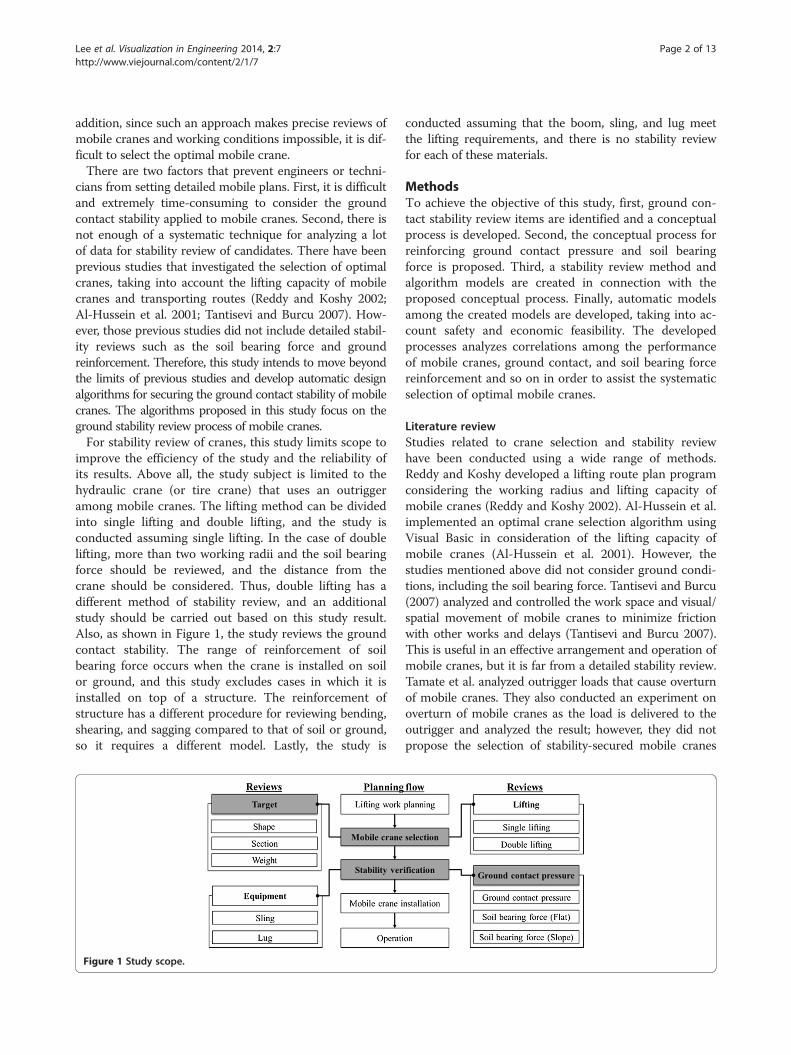
improve the efficiency of the study and the reliability ofits results. Above all, the study subject is limited to thehydraulic crane (or tire crane) that uses an outriggeramong mobile cranes. The lifting method can be dividedinto single lifting and double lifting, and the study isconducted assuming single lifting. In the case of doublelifting, more than two working radii and the soil bearingforce should be reviewed, and the distance from thecrane should be considered. Thus, double lifting has adifferent method of stability review, and an additionalstudy should be carried out based on this study result.Also, as shown in Figure 1, the study reviews the groundcontact stability. The range of reinforcement of soilbearing force occurs when the crane is installed on soilor ground, and this study excludes cases in which it isinstalled on top of a structure. The reinforcement ofstructure has a different procedure for reviewing bending,shearing, and sagging compared to that of soil or ground,so it requires a different model. Lastly, the study is
Figure 1 Study scope.
conducted assuming that the boom, sling, and lug meetthe lifting requirements, and there is no stability reviewfor each of these materials.
MethodsTo achieve the objective of this study, first, ground con-tact stability review items are identified and a conceptualprocess is developed. Second, the conceptual process forreinforcing ground contact pressure and soil bearingforce is proposed. Third, a stability review method andalgorithm models are created in connection with theproposed conceptual process. Finally, automatic modelsamong the created models are developed, taking into ac-count safety and economic feasibility. The developedprocesses analyzes correlations among the performanceof mobile cranes, ground contact, and soil bearing forcereinforcement and so on in order to assist the systematicselection of optimal mobile cranes.
Literature reviewStudies related to crane selection and stability reviewhave been conducted using a wide range of methods.Reddy and Koshy developed a lifting route plan programconsidering the working radius and lifting capacity ofmobile cranes (Reddy and Koshy 2002). Al-Hussein et al.implemented an optimal crane selection algorithm usingVisual Basic in consideration of the lifting capacity ofmobile cranes (Al-Hussein et al. 2001). However, thestudies mentioned above did not consider ground condi-tions, including the soil bearing force. Tantisevi and Burcu(2007) analyzed and controlled the work space and visual/spatial movement of mobile cranes to minimize frictionwith other works and delays (Tantisevi and Burcu 2007).This is useful in an effective arrangement and operation ofmobile cranes, but it is far from a detailed stability review.Tamate et al. analyzed outrigger loads that cause overturnof mobile cranes. They also conducted an experiment onoverturn of mobile cranes as the load is delivered to theoutrigger and analyzed the result; however, they did notpropose the selection of stability-secured mobile cranes

Lee et al. Visualization in Engineering 2014, 2:7 Page 3 of 13http://www.viejournal.com/content/2/1/7
and plate design algorithms like this study (Tamate et al.2005). Shapira et al. considered the characteristics ofbuilding projects and conducted a study in selecting whethera mobile crane or a tower crane is most suitable. Also, theitems to consider in choosing the detailed model (building,site, safety, air, weather, etc.) were analyzed to identify theimportance of each item (Shapira and Schexnayder 1999).However, there was no stability review or selection procedurein relation to the items considered. Alkass and Osamadeveloped a simulation program to select cranes byusing tools like database management, spreadsheet ap-plication programs, graphics, and simulation (Al-Husseinet al. 1997). Similarly, Struková and Ištvánik developed aprogram to select the optimal location of mobile cranesconsidering the lifting location, weight and building shape(Struková and Ištvánik 2011). However, there was notenough detailed review on stability of the soil bearing forceand the program was aimed at selecting cranes in consider-ation of lifting conditions such as the weight, height, andbuilding shape.Furusaka and Gray used the objective function that
minimizes rental, installation, and disconnection costs toselect an optimal crane, proposing a model that combinesvarious tower cranes (Furusaka and Gray 1984). However,their proposal was not a stability review of mobile cranes.Gray and Little suggested a process of selecting mobilecranes and tower cranes that suit designs at the initial de-sign phase (Gray and Little 1985). However, there was nomethod of reviewing the stability of the selected cranes orof using the available crane information in the market. Aliet al. studied collision avoidance upon the double lifting ofa mobile crane, and Perez et al. developed an algorithmfor planning collision-free paths among polyhedral ob-stacles (Lozano-Pérez and Wesley 1979). Other studiesinclude those conducted by Maczynski and Wojciech,who developed a 3D optimization algorithm of a rotat-ing part to secure rigidity of mobile cranes (Maczynskiand Wojciech 2003), and Lin and Haas (1996), who de-veloped a double lifting simulation program (Lin andHaas 1996). These studies did not consider the groundcontact stability of mobile cranes. Lastly, Ho et al. stud-ied a method of reviewing the ground contact stabilityof mobile cranes, but only main items were explainedand a formula was proposed (lacking detailed review itemsand procedure), and no automatic model was proposed(Ho, Seo and Kim 2007). Thus, this study proposes de-tailed review items and procedure regarding ground con-tact stability to secure the stability of mobile cranes, anddevelops an automatic model.
Review process of ground contact stabilityTable 1 shows review items of automatic design algorithmsfor securing the ground stability of mobile cranes. The re-view items are divided into review of objects to be lifted,
equipment information, review of ground contact pressureand reinforcement on soil bearing force of flat and slop-ping site. When examining the ground contact pressure,the maximum reaction of the outrigger is calculated tocheck stability and the available mobile cranes are identified.When the mobile cranes are selected, the reinforcement ofsoil bearing force is reviewed based on the ground shape. Atthe reinforcement planning of soil bearing force of flat siteas illustrated in Plate type (steel, timber), rigidity of plate, soilbearing force, and bending moment and shearing force act-ing on plate should be reviewed. At the reinforcement plan-ning of soil bearing force of slopping site, slope data such asslopping angle, slopping length, slopping height, and distrib-uted load on soil should be examined additionally to designa plate. Here the most optimal plate is designed dependingon the crane type and the ground state.Figure 2 shows the ground contact stability review
process. The crane operation plan is classified into review-ing lifting conditions, mobile crane selection, and review-ing ground contact stability. When reviewing liftingconditions, the shape, section, and weight of lifting objectsshould be checked.
Automatic review and design algorithmsReview of basic information in selecting cranesThe lifting plans and crane selection have complex, dy-namic correlations, so the influencing factors include notonly the duration and cost in terms of construction man-agement, but also the working radius, work efficiency,interference with nearby buildings and other works, quan-tity, location selection, site installation, and disconnection,all of which should be taken into consideration (Lin andHaas 1996). The optimal mobile crane is selected consid-ering these factors, and a respective plan should be set bystep in order.For the stability review of mobile cranes, the characteris-
tics, and heights of lifting objects and the distance from acrane should be reviewed as shown in Figure 3. The charac-teristics of objects to be lifted refer to the shape, weight,and materials, and the crane characteristics indicate the lift-ing capacity, available lifting height, and turning radius ofthe boom. These basic factors should be considered whenselecting a crane or cranes, and cranes that do not satisfythe given factors are excluded from analyses. In addition,the ground contact stability should be examined based onthese factors to prevent overturn of mobile cranes.
Review of ground contact pressureAs shown in Figure 4, the ground contact model of thisstudy calculates the maximum ground contact load ac-cording to the boom location (A, B, C). The maximumreaction is at the outrigger when the boom is at point B.However, this cannot be seen as the point where themaximum reaction is realized, because B is not the main

Table 1 Review items for ground contact stability
Step Items reviewed
Basic Items Review of the objects to be lifted Type, material and weight
Equipment Information Working radius, the maximum height of objects, crane weight and outrigger radius
Ground contactstability
Review of ground contact pressure Work direction, ratio of impact load and the maximum reaction of outrigger
Reinforcement of soil bearing force(flat site)
Plate type (steel, timber), rigidity of plate, soil bearing force, bending moment, andshearing force acting on plate
Reinforcement of soil bearing force(slopping site)
Additional data including slope data such as slopping angle, slopping length, sloppingheight, and distributed load on soil
Lee et al. Visualization in Engineering 2014, 2:7 Page 4 of 13http://www.viejournal.com/content/2/1/7
location of the work, and instead is where temporary rota-tion and passing are demonstrated. Thus, when the boomis located at A (the main location of work), it is regardedas the maximum reaction. Also, considering that theboom rotates at B, 50% of the maximum reaction forceshould be added for safe design (Ho, Seo and Kim 2007).The formula is as shown in Equations 1 and 2.When the impact load is not considered:
Pmax ¼ 0:85 � W þW 1ð Þ � 0:5� 1:5 ð1Þwhere Pmax is the maximum reaction, w is the crane
weight, and W1 is the lift weight.When the impact load is considered:
Pmax ¼ 0:85� W þW 1ð Þ � 1:3f g � 0:5� 1:5 ð2ÞFigure 5 shows the ground contact stability review
process. The crane operation plan is classified intoreviewing lifting conditions, mobile crane selection, andreviewing ground contact stability. When reviewing lift-ing conditions, the shape, section, and weight of liftingobjects should be checked. The ground contact pressure
Figure 2 Ground contact stability review process.
of the outrigger is then reviewed along with the liftingconditions when selecting mobile cranes. This is Simula-tion 1 proposed in the study. When reviewing groundcontact stability, soil bearing force is reviewed based onthe results of Simulation 1. Soil bearing force is reviewedseparately by flat and slopping site, and each process isdeveloped as in Simulations 2 and 3, respectively.The generation model for stability review of ground
contact stability uses the specifications provided by thecrane manufacturer and the project information. Engi-neers and technicians should set the project informationas shown in Figure 6, and the crane information isautomatically imported from data that has already beenimplemented. The ground contact pressure can be ex-amined based on the outrigger span, the turning radiusof boom, the body weight, and the lift weight.The simulation model for automatic stability review of
ground contact stability is designed to review all MCs.As illustrated in Figure 7, the simulation model sets theinstallation location for all MCs and examines the groundcontact pressure automatically by the simulation algo-rithms illustrated in Figure 7.
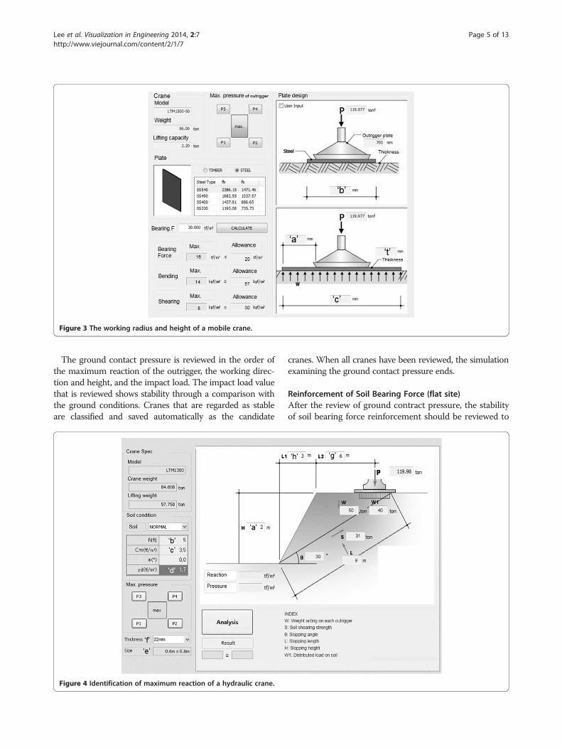
Figure 3 The working radius and height of a mobile crane.
Lee et al. Visualization in Engineering 2014, 2:7 Page 5 of 13http://www.viejournal.com/content/2/1/7
The ground contact pressure is reviewed in the order ofthe maximum reaction of the outrigger, the working direc-tion and height, and the impact load. The impact load valuethat is reviewed shows stability through a comparison withthe ground conditions. Cranes that are regarded as stableare classified and saved automatically as the candidate
Figure 4 Identification of maximum reaction of a hydraulic crane.
cranes. When all cranes have been reviewed, the simulationexamining the ground contact pressure ends.
Reinforcement of Soil Bearing Force (flat site)After the review of ground contract pressure, the stabilityof soil bearing force reinforcement should be reviewed to

Figure 5 Generation model for ground contact stability review.
Lee et al. Visualization in Engineering 2014, 2:7 Page 6 of 13http://www.viejournal.com/content/2/1/7
prevent overturn. The reinforcement of soil bearing forceis reviewed under 2 different ground conditions: a flat anda slopping site. For the flat site, the plate material, thick-ness, and area should be reviewed manually by the user asshown in Figure 8 or automatically by the simulation algo-rithm as shown in Figure 9. Since the plate transfers theground contact load of the outrigger to the ground, itshould be designed after checking the adhesive power andthe rigidity of the plate. The plate is usually made of tim-ber and steel, and data including bending and shearing ac-cording to the thickness and area should be gathered tobe automatically applied to the simulation.As shown in Figure 10 the generation model of soil
bearing force reinforcement as plate reinforcement im-ports the additional data on ground contact pressure ofthe outrigger stored in the system implemented by theproposed algorithms besides the basic information speci-fied in Table 1. Based on such data, the plate type, rigid-ity, bearing soil force, and bending and shearing factorsare automatically reviewed for reinforcement of soil bearing
Figure 6 Input page of crane information.
force. When the plate fails to transfer the ground contactload to the ground, the crane is likely to overturn. For aslope, the soil type, soil property value and slope informa-tion should also be examined. When stability reviews of allitems are completed, the crane and the suitable plate designare saved in pairs.The automatic plate design for reinforcement of the soil
bearing force on a flat site is applied with information likethe outrigger of the candidate cranes drawn from simula-tion 1 as shown in Figure 7 and the body weight. For theplate design in simulation 2, the outrigger of a crane asshown in Figure 9 is selected, and the plate materials andallowable soil bearing force are checked for the design ofthe materials. The designed plate and the crane are savedin pairs within the scope that stability is secured. Simula-tion 2 is completed when all the candidate cranes deducedfrom simulation 1 are reviewed.As demonstrated in Figure 11, the program automatic-
ally reviews the plate design for reinforcement of soil bear-ing force on a flat site. The rigidity of plates by type andsize is imported from the gathered data, and the max-imum ground contact load of the outrigger is insertedbased on the result of simulation 1. Also, the crane weightand lifting capacity imported from the crane data areinserted. The values are saved after the soil bearing forceand the plate’s bending and shearing are reviewed.The plate for reinforcement of soil bearing force on a
flat site is divided into timber and steel for the design de-pending on the material used, and the soil bearing force,
Figure 7 Automatic ground contact pressure review(simulation 1).

Figure 8 Design of a reinforcement plate (flat site).
Figure 9 Automatic plate design for flat site (simulation 2).
Lee et al. Visualization in Engineering 2014, 2:7 Page 7 of 13http://www.viejournal.com/content/2/1/7
bending, and shearing should be automatically reviewedby the equations (3) to (7). Steel plate review items can bedescribed as follows (Shapiro et al. 2000). Figure 11 showsthe variables related to plate design (a, b, c, and t), whichshould meet the three requirements regarding soil bearingforce, bending, and shearing in the automatic designalgorithm.
Soil bearing force review
q ¼ Pbc
≤qa−−−−−−−O:K ð3Þ
P: Maximum Reaction,qa: Allowable Soil Bearing Force
Bending review
M ¼ qba2
2
f1 ¼ 3qa12
t2≤fb−−−−−−−O:K ð4Þ
f2 ¼ 3qa22
t2≤fb−−−−−−O:K ð5Þ
M: bending Moment,f1: Transversal Bending Stress,f2: Longitudinal Bending Stress,fb: Allowable Bending Stress,a1: Transversal Direction a,a2: Longitudinal Direction a,t: Thickness of member
Shearing review
v1 ¼ 1:5qa1t
≤fs−−−−−−−−O:K ð6Þ
v2 ¼ 1:5qa2t
≤fs−−−−−−−O:K ð7Þ
v1: Transversal, horizontal shear stressv2: Longitudinal, horizontal shear stress,fs: Allowable shear stress of member
Reinforcement of Soil Bearing Force (slopping site)For the reinforcement of the soil bearing force of aslope, an additional review of the slope shape and thesoil property value is required. As shown in Figure 12,the reinforcement plate is designed after reviewing thevertical weight, shearing strength, sliding angle, slopelength, and height. The reinforcement plate installed ona slope should consider not only the transfer of load, butalso the landslide at the slope.The plate for reinforcement of the soil bearing force on
a slope requires reviews of soil bearing force, bending, andshearing. Steel plate review items are described as follows(Shapiro et al. 2000). Figure 11 shows the variables related

Lee et al. Visualization in Engineering 2014, 2:7 Page 8 of 13http://www.viejournal.com/content/2/1/7
to plate design and slope shape (a, b, c, d, e, f, g, h, and t),and the variables related to plate design (e, f) should meetthree requirements regarding soil bearing force, bending,and shearing in the automatic design algorithm.
Subgrade reaction (q)
q ¼ Pmax � n t=m2� � ð8Þ
Reaction area (A)
A ¼ Pq
m2� � ð9Þ
Therefore, the longitudinal reaction force L3 is as-sumed to have a square distribution.
L3 ¼ffiffiffiffiA
pmð Þ
Vertical sliding force
Figure 10 Generation model for plate stability review.
L2 ¼ gþ L3=2 mð Þ ð10Þ
Wa ¼ 1=2� d� a� L2 ð11Þ
W ¼ Waþ q� L3ð Þ tð Þ ð12Þ
Shearing strength S
L ¼ffiffiffiffiffiffiffiffiffiffiffiffiffiffiffiffiffiffiffiffiffiffiffiffiffiffiffiffiffiffiffiffiffiffia2 þ hþ L2ð Þ2� �q
ð13Þ
θ ¼ tan−1a
hþ L2
� �ð14Þ
S ¼ c� LþWcosθ� tanΦm ð15Þ
Φm: Friction angle
Safety angle

Figure 11 Plate design information (flat site).
Figure 12 Plate design information (slopping site).
Lee et al. Visualization in Engineering 2014, 2:7 Page 9 of 13http://www.viejournal.com/content/2/1/7

Figure 13 Automatic plate design for slopping site(simulation 3).
Figure 14 Automatic design model.
Lee et al. Visualization in Engineering 2014, 2:7 Page 10 of 13http://www.viejournal.com/content/2/1/7
Fa ¼ SW � sinθ
> 1:2−−−−−−−O:K ð16Þ
As illustrated in Figure 13, the plate design of a slopeanalyzes the candidate cranes deduced from simulation1 as illustrated in Figure 7. In simulation 3, the plate isdesigned by checking the soil properties such as the Nvalue, adhesive power, friction angle, and weight of unitvolume that are input manually by the user as shown inFigure 12. Also, the slope shape is automatically ana-lyzed by the equations (8) to (16) to review both the soilbearing force of the soil/ground and the landslide. Forthe plate design in simulation 3, the outrigger of a craneas shown in Figure 13 is selected, and the plate materialsand the allowable soil bearing force are checked for thedesign of the materials. The designed plate and the craneare saved in pairs within the scope that stability is se-cured. Simulation 3 is automatically completed when allthe candidate cranes deduced from simulation 1 arereviewed.The top level process for mobile crane plans is com-
prised of 3 simulations, as illustrated in Figure 14. When
selecting mobile cranes (Figure 7), the project data andcrane data are used to deduce the candidate craneswithin the required ground contact pressure. It shouldbe checked whether the mobile crane is available in themarket, and the selected cranes become the basis for theplate design in simulation 2 or 3.As previously described, only 1 type is simulated accord-
ing to the ground shape for both simulations (2 & 3), andthe plate suitable for the candidate crane is designed. Theplate design is paired with the candidate crane for a reviewof economic feasibility, and is then finally selected.This study proposes a model for selecting mobile cranes
with the lowest cost possible, and designing plates byidentifying multiple cases and calculating cost based onsecuring stability, which is the prerequisite. The objectivevariable of mobile crane and plate design is cost (Cmc).The objective function of this model is to minimize thesum of mobile crane rental cost (Crental) and plate cost(Cplate) as shown in Formula 17. The cost calculation ofthe model shown in Figure 14 is automatically carried outin 2 steps. First, a rental cost is calculated from the data ofn candidate cranes. Second, respective cost is calculatedfor ‘m’ plates designed in simulations 2 and 3. The modelaims to estimate the minimum cost, and the objective andconstraint functions are as shown below.
Minimize Cmcf g ð17ÞCmc ¼ Crental þ Cplate
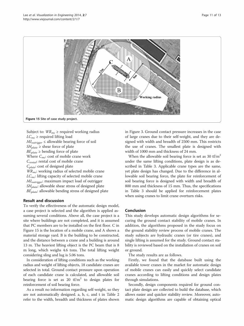
Figure 15 Site of case study project.
Lee et al. Visualization in Engineering 2014, 2:7 Page 11 of 13http://www.viejournal.com/content/2/1/7
Subject to: WRmc ≥ required working radiusLCmc ≥ required lifting loadMIoutrigger ≤ allowable bearing force of soilSHplate ≥ shear force of plateBEplate ≥ bending force of plateWhere Cmc: cost of mobile crane workCrental: rental cost of mobile craneCplate: cost of designed plateWRmc: working radius of selected mobile craneLCmc: lifting capacity of selected mobile craneMIoutrigger: maximum impact load of outriggerSHplate: allowable shear stress of designed plateBEplate: allowable bending stress of designed plate
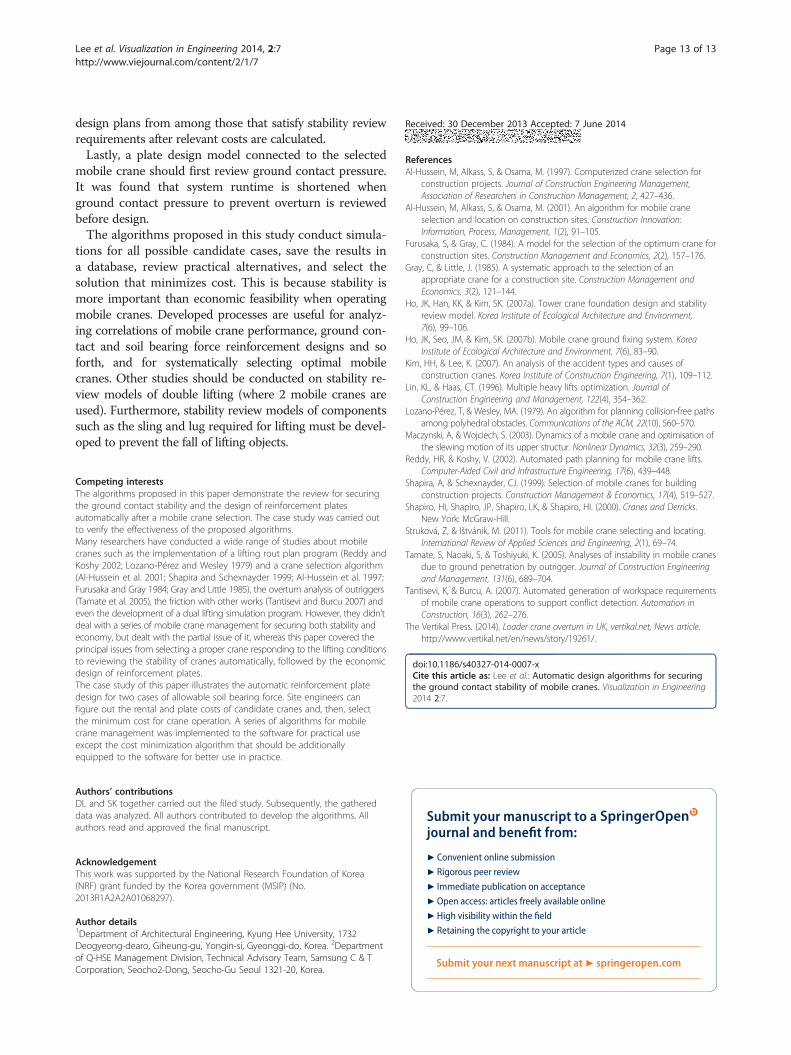
Result and discussionTo verify the effectiveness of the automatic design model,a case project is selected and the algorithm is applied as-suming several conditions. Above all, the case project is asite where buildings are not completed, and it is assumedthat PC members are to be installed on the first floor. C inFigure 15 is the location of a mobile crane, and A shows amaterial storage yard. B is the building to be constructed,and the distance between a crane and a building is around13 m. The heaviest lifting object is the PC beam that is 8m long, which weighs 4.6 tons. The total lifting weightconsidering sling and lug is 5.06 tons.In consideration of lifting conditions such as the working
radius and weight of lifting objects, 18 candidate cranes areselected in total. Ground contact pressure upon operationof each candidate crane is calculated, and allowable soilbearing force is set as 20 tf/m2 to design plates forreinforcement of soil bearing force.As a result no information regarding self-weight, so they
are not automatically designed. a, b, c, and t in Table 2refer to the width, breadth and thickness of plates shown
in Figure 3. Ground contact pressure increases in the caseof large cranes due to their self-weight, and they are de-signed with width and breadth of 2500 mm. This restrictsthe use of cranes. The smallest plate is designed withwidth of 1000 mm and thickness of 24 mm.When the allowable soil bearing force is set as 30 tf/m2
under the same lifting conditions, plate design is as de-scribed in Table 3. Applicable crane types are the same,yet plate design has changed. Due to the difference in al-lowable soil bearing force, the plate for reinforcement ofsoil bearing force is designed with width and breadth of800 mm and thickness of 15 mm. Thus, the specificationsin Table 3 should be applied for reinforcement plateswhen using cranes to limit crane overturn risks.
ConclusionThis study develops automatic design algorithms for se-curing the ground contact stability of mobile cranes. Inaddition, the algorithms proposed in the study focus onthe ground stability review process of mobile cranes. Thestudy subjects are hydraulic cranes (or tire cranes), andsingle lifting is assumed for the study. Ground contact sta-bility is reviewed based on the installation of cranes on soilor ground.The study results are as follows.Firstly, we found that the database built using the
available tower cranes in the market for automatic designof mobile cranes can easily and quickly select candidatecranes according to lifting conditions and design platesthrough simulations.Secondly, design components required for ground con-
tact plate design are collected to build the database, whichallows easier and quicker stability review. Moreover, auto-matic design algorithms are capable of obtaining optical

Table 2 Result of automatic design model (1)
Mobilecrane
Capacity(ton)
Groundcontactpressure(ton)
Steel plate
a (mm) b (mm) c (mm) t (mm)
TM1500 80 58.786 570 1750 1750 34
TG1500E 150 - - - - -
TG1000E 100 - - - - -
TG800E 80 33.316 420 1300 1300 26
TG8500EX 50 27.451 400 1200 1200 24
TG300E 30 - - - - -
SC50H 50.5 33.316 400 1200 1200 24
SC25H 25 27.451 300 1000 1000 18
LTM1500-84 500 121.801 900 2500 2500 54
LTM1500-50 500 121.801 900 2500 2500 54
LTM1400 400 124.988 900 2500 2500 54
LTM1300 300 114.151 900 2400 2400 54
LTM1200 200 87.376 750 2100 2100 45
LTM1160 160 73.351 670 1950 1950 40
LTM1120 120 43.516 450 1500 1500 27
LTM1090 100 46.576 520 1550 1550 31
LTM1070 70 40.647 470 1450 1450 28
LTM1060 70 39.245 470 1450 1450 28
Table 3 Result of automatic design model (2)
Mobilecrane
Capacity(ton)
Groundcontactpressure(ton)
Steel plate
a (mm) b (mm) c (mm) t (mm)
TM1500 80 58.786 390 1400 1400 29
TG1500E 150 - - - - -
TG1000E 100 - - - - -
TG800E 80 33.316 320 1100 1100 23
TG8500EX 50 27.451 300 1000 1000 21
TG300E 30 - - - - -
SC50H 50.5 33.316 300 1000 1000 22
SC25H 25 27.451 200 800 800 15
LTM1500-84 500 121.801 670 2050 2050 49
LTM1500-50 500 121.801 670 2050 2050 49
LTM1400 400 124.988 720 2050 2050 53
LTM1300 300 114.151 700 2000 2000 50
LTM1200 200 87.376 570 1750 1750 42
LTM1160 160 73.351 500 1600 1600 36
LTM1120 120 43.516 320 1250 1250 23
LTM1090 100 46.576 370 1250 1250 28
LTM1070 70 40.647 350 1200 1200 25
LTM1060 70 39.245 320 1150 1150 24
Lee et al. Visualization in Engineering 2014, 2:7 Page 12 of 13http://www.viejournal.com/content/2/1/7
Lee et al. Visualization in Engineering 2014, 2:7 Page 13 of 13http://www.viejournal.com/content/2/1/7
design plans from among those that satisfy stability reviewrequirements after relevant costs are calculated.Lastly, a plate design model connected to the selected
mobile crane should first review ground contact pressure.It was found that system runtime is shortened whenground contact pressure to prevent overturn is reviewedbefore design.The algorithms proposed in this study conduct simula-
tions for all possible candidate cases, save the results ina database, review practical alternatives, and select thesolution that minimizes cost. This is because stability ismore important than economic feasibility when operatingmobile cranes. Developed processes are useful for analyz-ing correlations of mobile crane performance, ground con-tact and soil bearing force reinforcement designs and soforth, and for systematically selecting optimal mobilecranes. Other studies should be conducted on stability re-view models of double lifting (where 2 mobile cranes areused). Furthermore, stability review models of componentssuch as the sling and lug required for lifting must be devel-oped to prevent the fall of lifting objects.
Competing interestsThe algorithms proposed in this paper demonstrate the review for securingthe ground contact stability and the design of reinforcement platesautomatically after a mobile crane selection. The case study was carried outto verify the effectiveness of the proposed algorithms.Many researchers have conducted a wide range of studies about mobilecranes such as the implementation of a lifting rout plan program (Reddy andKoshy 2002; Lozano-Pérez and Wesley 1979) and a crane selection algorithm(Al-Hussein et al. 2001; Shapira and Schexnayder 1999; Al-Hussein et al. 1997;Furusaka and Gray 1984; Gray and Little 1985), the overturn analysis of outriggers(Tamate et al. 2005), the friction with other works (Tantisevi and Burcu 2007) andeven the development of a dual lifting simulation program. However, they didn’tdeal with a series of mobile crane management for securing both stability andeconomy, but dealt with the partial issue of it, whereas this paper covered theprincipal issues from selecting a proper crane responding to the lifting conditionsto reviewing the stability of cranes automatically, followed by the economicdesign of reinforcement plates.The case study of this paper illustrates the automatic reinforcement platedesign for two cases of allowable soil bearing force. Site engineers canfigure out the rental and plate costs of candidate cranes and, then, selectthe minimum cost for crane operation. A series of algorithms for mobilecrane management was implemented to the software for practical useexcept the cost minimization algorithm that should be additionallyequipped to the software for better use in practice.
Authors’ contributionsDL and SK together carried out the filed study. Subsequently, the gathereddata was analyzed. All authors contributed to develop the algorithms. Allauthors read and approved the final manuscript.
AcknowledgementThis work was supported by the National Research Foundation of Korea(NRF) grant funded by the Korea government (MSIP) (No.2013R1A2A2A01068297).
Author details1Department of Architectural Engineering, Kyung Hee University, 1732Deogyeong-dearo, Giheung-gu, Yongin-si, Gyeonggi-do, Korea. 2Departmentof Q-HSE Management Division, Technical Advisory Team, Samsung C & TCorporation, Seocho2-Dong, Seocho-Gu Seoul 1321-20, Korea.
Received: 30 December 2013 Accepted: 7 June 2014
ReferencesAl-Hussein, M, Alkass, S, & Osama, M. (1997). Computerized crane selection for
construction projects. Journal of Construction Engineering Management,Association of Researchers in Construction Management, 2, 427–436.
Al-Hussein, M, Alkass, S, & Osama, M. (2001). An algorithm for mobile craneselection and location on construction sites. Construction Innovation:Information, Process, Management, 1(2), 91–105.
Furusaka, S, & Gray, C. (1984). A model for the selection of the optimum crane forconstruction sites. Construction Management and Economics, 2(2), 157–176.
Gray, C, & Little, J. (1985). A systematic approach to the selection of anappropriate crane for a construction site. Construction Management andEconomics, 3(2), 121–144.
Ho, JK, Han, KK, & Kim, SK. (2007a). Tower crane foundation design and stabilityreview model. Korea Institute of Ecological Architecture and Environment,7(6), 99–106.
Ho, JK, Seo, JM, & Kim, SK. (2007b). Mobile crane ground fixing system. KoreaInstitute of Ecological Architecture and Environment, 7(6), 83–90.
Kim, HH, & Lee, K. (2007). An analysis of the accident types and causes ofconstruction cranes. Korea Institute of Construction Engineering, 7(1), 109–112.
Lin, KL, & Haas, CT. (1996). Multiple heavy lifts optimization. Journal ofConstruction Engineering and Management, 122(4), 354–362.
Lozano-Pérez, T, & Wesley, MA. (1979). An algorithm for planning collision-free pathsamong polyhedral obstacles. Communications of the ACM, 22(10), 560–570.
Maczynski, A, & Wojciech, S. (2003). Dynamics of a mobile crane and optimisation ofthe slewing motion of its upper structur. Nonlinear Dynamics, 32(3), 259–290.
Reddy, HR, & Koshy, V. (2002). Automated path planning for mobile crane lifts.Computer-Aided Civil and Infrastructure Engineering, 17(6), 439–448.
Shapira, A, & Schexnayder, CJ. (1999). Selection of mobile cranes for buildingconstruction projects. Construction Management & Economics, 17(4), 519–527.
Shapiro, HI, Shapiro, JP, Shapiro, LK, & Shapiro, HI. (2000). Cranes and Derricks.New York: McGraw-Hill.
Struková, Z, & Ištvánik, M. (2011). Tools for mobile crane selecting and locating.International Review of Applied Sciences and Engineering, 2(1), 69–74.
Tamate, S, Naoaki, S, & Toshiyuki, K. (2005). Analyses of instability in mobile cranesdue to ground penetration by outrigger. Journal of Construction Engineeringand Management, 131(6), 689–704.
Tantisevi, K, & Burcu, A. (2007). Automated generation of workspace requirementsof mobile crane operations to support conflict detection. Automation inConstruction, 16(3), 262–276.
The Vertikal Press. (2014). Loader crane overturn in UK, vertikal.net, News article.http://www.vertikal.net/en/news/story/19261/.
doi:10.1186/s40327-014-0007-xCite this article as: Lee et al.: Automatic design algorithms for securingthe ground contact stability of mobile cranes. Visualization in Engineering2014 2:7.
Submit your manuscript to a journal and benefi t from:
7 Convenient online submission
7 Rigorous peer review
7 Immediate publication on acceptance
7 Open access: articles freely available online
7 High visibility within the fi eld
7 Retaining the copyright to your article
Submit your next manuscript at 7 springeropen.com