Embed Size (px)
Citation preview
Hindawi Publishing CorporationMathematical Problems in EngineeringVolume 2013 Article ID 601508 12 pageshttpdxdoiorg1011552013601508
Research ArticleNew Mathematical Modelling of Stabilizing Pile withPrestressed Tieback Anchors
Cheng Huang Wei-zhong Ren and Ling-wei Kong
State Key Laboratory of Geomechanics and Geotechnical Engineering Institute of Rock and Soil MechanicsChinese Academy of Sciences Wuhan 430071 China
Correspondence should be addressed to Cheng Huang tjhuangcheng163com
Received 12 April 2013 Accepted 11 August 2013
Academic Editor Shihua Li
Copyright copy 2013 Cheng Huang et al This is an open access article distributed under the Creative Commons Attribution Licensewhich permits unrestricted use distribution and reproduction in any medium provided the original work is properly cited
This paper presents a novel mathematical modelling for analyzing stabilizing piles with prestressed tieback anchors The newdifferential equations governing the mechanical response of the stabilizing pile are formulated and the boundary conditionsconsidering the tie-back anchors are mathematically specified Then the system of differential equations is numerically solved bythe high-accuracy Runge-Kutta finite differencemethod A simple computer programhas beenwritten on the platformofMATLABto run the procedure of the proposed algorithmThis approach is entirely different from the traditional finite element method usedto design the anchored piles The FEM is employed to verify the feasibility of the developed method The comparative case studyindicates that the proposed method has more higher modeling and computing efficiency than the FEM and can be an alternativemethod for designing the anchored pile used for slope stabilization
1 Introduction
For many years the stabilizing piles built in China to stabi-lize existing or potential landslides were mostly cantileverLater prestressed ground anchors were added to reducethe number and size of the piles It is shown that anchorprestressing plays an important role in limiting maximumbending moment on the piles and controlling deflection ofthe pile head So anchored stabilizing piles offer considerableeconomic advantages over the conventional cantilevered piles[1ndash4] Combined pile tieback anchor systems will find moreextensive use as slope stabilization systems in the future
Existing methods for the analysis of stabilizing piles withprestressed tie-back anchor can be generally classified intothe following two categories [5ndash9] (a) coupled methods(also called continuum analysis) that simultaneously solvepile response and slope stability [10ndash13] and (b) uncoupledmethods which deal with pile and slope separately In theuncoupled method the pile response is analyzed using thebeam on elastic foundation approach or FEM and pile-soil interaction is represented by equivalent Winkler or p-ysprings [14ndash20]
The finite element method is certainly the most com-prehensive coupled method to study pile-slope stabilityHowever its use generally requires high numerical costs andaccurate measurements of material properties This makesthe use of coupled approach rather unattractive for practicalapplications
To date in practical engineering applications the uncou-pled method is the most widely used approach to design thereinforcing piles to increase slope stability due to its simplicityof use First the lateral force acting on the pile segment abovethe slip surface due to soil movement is evaluated usuallyby the limit equilibrium method Second the response ofthe anchored pile subjected to lateral loading is analysed byFEM modeling it as a beam resting on linear or nonlinearsoilrock spring supports And we know the conventionalsubgrade reaction solution available in literature can not takeinto account the tie-back anchors [15 18 19]
In this paper a new uncoupled method to computethe response of anchored piles subjected to lateral earthpressure loading based on new boundary-value problemapproach is introduced This approach is entirely differentfrom the traditional finite element method using the beam
2 Mathematical Problems in Engineering
Pile
Deflectedcenterline
Q
Mw
z
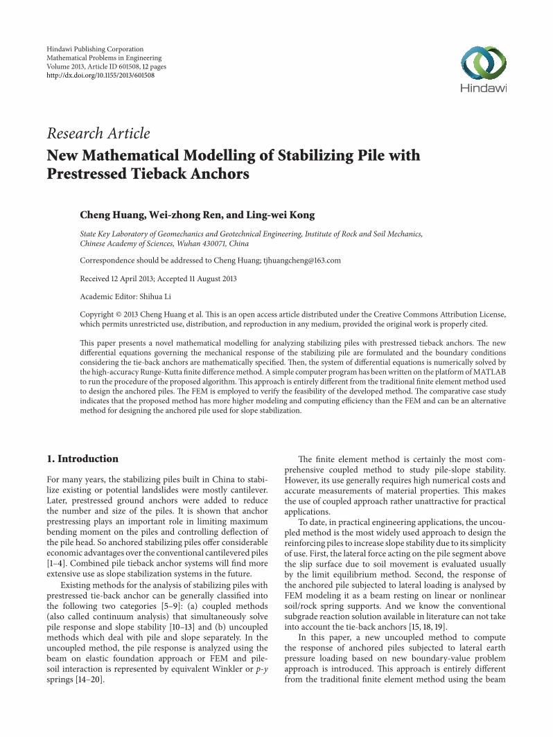
Figure 1 The coordinate system of laterally loaded pile model
elements and spring elements to model the anchored pilesIn the following first the new governing differential equa-tions including six variables (three internal forces and threedisplacements) are formulated and the boundary conditionconsidering the tie-back anchor is given Second the highaccuracy Runge-Kutta differential method is used to solve thecorresponding system of differential equations to obtain thepilersquos internal forces displacements and the anchorrsquos internalforce A program for anchored pile response analysis andgraphics edit is developed At last the program was verifiedagainst the FEM analysis results in terms of pile deflectionbendingmoment and shear force along the length of the pile
The aim of this work is to present an alternative approachbased on new governing differential equations to analyze theresponse of anchored piles used for slope stabilization orearth retainingThe efficiency and accuracy of this developedmethod are demonstrated through comparative case study
2 Differential Equations Governingthe Response of Stabilizing Pile
As known in order to solve the complicated engineeringproblem of the response of stabilizing pile with prestressedtie-back anchors by using an accurate mathematical methodit is often needed to define its boundary-value problemwhichinvolves the governing differential equations and correspond-ing boundary conditions Then closed form or numericalsolutions for the engineering problem can be obtained bymany appropriate mathematical methods
21 Conventional Governing Differential Equation for PileDeflection Before deducing the new differential equationsgoverning the arching mechanism of stabilizing piles weneed to review the conventional governing differential equa-tions for pile deflections which can be found in many of theavailable literature [1 15] It is reported here only for the sakeof completeness
We assume a planar cartesian coordinate system 119908-119911 asshown in Figure 1 with its origin at the center of the pile head
such that the 119911-axis coincides with the pile axis and the 119908-119911plane coincides with the plane of the paper A lateral force 119876and a moment119872 are assumed to be applied at the pile head
The pile-soil interaction response can be idealised as avertical beam placed in a Winkler spring medium The pilematerial is assumed to follow linear elastic behaviour
We know that vertical piles resist lateral loads ormomentsby deflecting until the necessary reaction in the surroundingsoil is mobilized
Neglecting the friction force along the pile-soil interfacethe deflection response of piles subjected to lateral load andconstrained by surrounding Winkler springs is governed bythe following differential equation
119864119868
1198894119908 (119911)
1198891199114
+ 119896 (119911)119908 (119911) 119887 = 0 (1)
where 119911 is the position coordinate 119908(119911) is the deflectionfunction of the pile (it has a unit of length) 119864 is the pilersquosYoungrsquos modulus 119868 is the second moment of inertia of thepilersquos cross-section (119864119868 is called the flexural rigidity of thepile) 119896 is the spring constant also called the modulus ofhorizontal subgrade reaction (it has a unit of forcelength3)which can be assumed to vary linearly with depth for soilor to remain unchanged for rock Much of the availableengineering experience and assumptions can be used todetermine its value and 119887 is the section width
Based on (1) the deflection function119908(119911) can be obtainedby power series solution finite difference method and FEMin terms of bar and beam The detailed solution schemecan be found in many of the available literature Once thedeflection function119908(119911) is established the bending momentshear force and soil reaction force at various depths along thepile can be deduced by differentiating the deflection functionas follows
120593 =
119889119908
119889119911
119872 = minus119864119868
1198892119908
1198891199112
119876 = minus119864119868
1198893119908
1198891199113
(2)
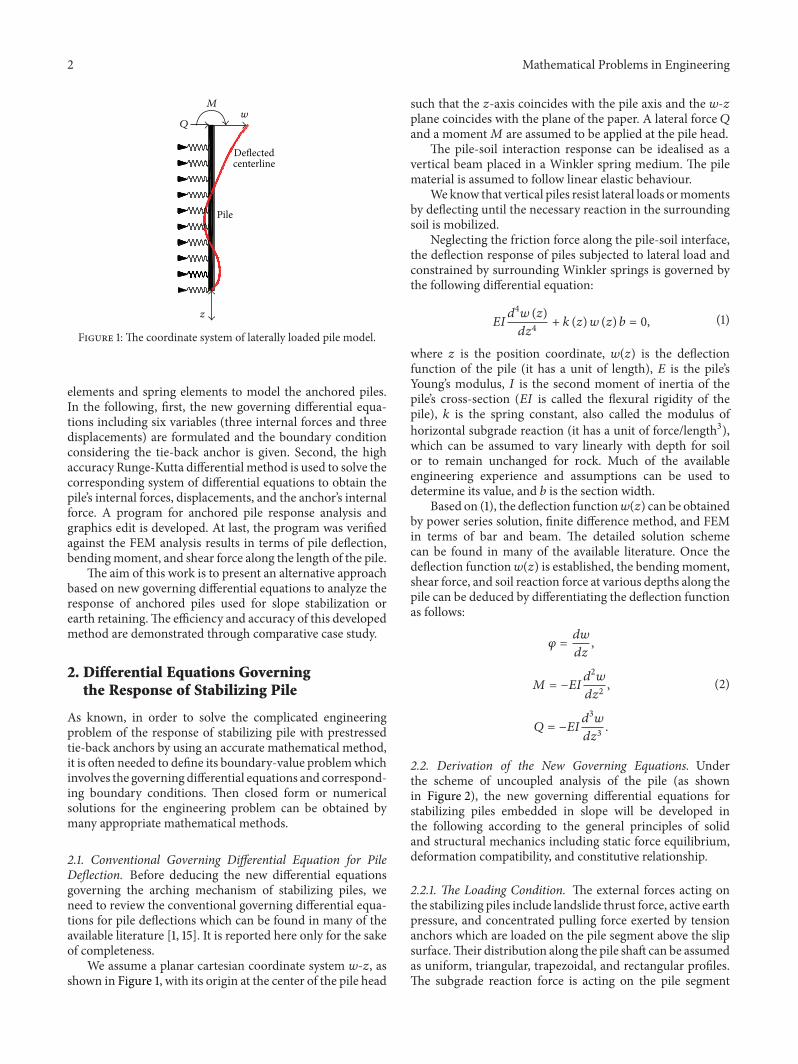
22 Derivation of the New Governing Equations Underthe scheme of uncoupled analysis of the pile (as shownin Figure 2) the new governing differential equations forstabilizing piles embedded in slope will be developed inthe following according to the general principles of solidand structural mechanics including static force equilibriumdeformation compatibility and constitutive relationship
221 The Loading Condition The external forces acting onthe stabilizing piles include landslide thrust force active earthpressure and concentrated pulling force exerted by tensionanchors which are loaded on the pile segment above the slipsurfaceTheir distribution along the pile shaft can be assumedas uniform triangular trapezoidal and rectangular profilesThe subgrade reaction force is acting on the pile segment
Mathematical Problems in Engineering 3
Sliding mass
Slope surface
Mobilized soil
pressure
Slip surface
Stable substratumBeamon
elasticfoundation
Prestressed anchor
Figure 2The uncoupled analysis model for the stabilizing pile withprestressed tieback anchor
below the slip surface These external forces considered arein equilibrium
222 The Pile-Soil Interaction Model Due to its simplicityand efficiency of use the Winkler soil model is also adoptedin the current analysis to describe the pile-soil interactionbehavior Winkler method assumed that the substratum iscomposed of independent horizontal springs Under theWinkler hypothesis the soil reaction pressures (119901) acting onthe pile can be modeled by discrete independent linear ornonlinear springs in form of the following equation
119901 = 119896 sdot 119908 (3)
where 119901 is the horizontal soil reaction pressure (it has a unitof forcelength2)
223 The New Equilibrium Differential Equations Consid-ering an isolated free portion of pile as shown in Figure 3having an infinitesimal length of 119889119904 and acted upon byexternal distributed normal load 119902
119899and tangential load 119902
120591
The free segment can be imagined to be cut out of the pileand the internal forces (119872119873 and119876) in the original pile maybecome external forces on the isolated free portion
We define sign conventions so that the six variables asshown in Figure 3 are positive The sign convention adoptedfor forces is that positive sign indicates tensile axial force119873 the positive shearing force 119876 should be directed so thatthey will tend to rotate the element counterclockwise andthe positive bending moment 119872 will tend to make theelement be concave leftward The sign convention adoptedfor displacements is that the positive normal displacement Vpoints outward normal the positive tangential displacement119906 points right when facing outward normal the positive 120593 iscounterclockwise
Thus considering the equilibrium of the above infinitesi-mal pile segment under the action of the applied loads (shownin Figure 3) we arrive at two force equilibrium equations
M+dM
dsds
Q +dQ
dsds N +
dN
dsds
kn
ks
Q
N
M
qn
uds
q120591
120593
Figure 3 The free body diagram of infinitesimal isolated segmentof pile
in the direction of 119906 and V and one moment equilibriumequation
(119873 +
119889119873
119889119904
119889119904) minus 119873 minus 119902120591119889119904 minus 119896
119904119906119863119889119904 = 0
(119876 +
119889119876
119889119904
119889119904) minus 119876 minus 119902119899119889119904 minus 119896
119899V119887119889119904 = 0
(119872 +
119889119872
119889119904
119889119904) minus119872 + (119876 +
119889119876
119889119904
119889119904)
119889119904
2
+ 119876
119889119904
2
= 0
(4)
Simplifying the above equations and neglecting thehigher order terms and the terms with the square of thedifferential the equilibrium equations now take the followingform
119889119873
119889119904
= 119896119904119863119906 + 119902
120591
119889119876
119889119904
= 119896119899119887V + 119902
119899
119889119872
119889119904
= minus119876
(5)
where 119878 is the position coordinate and 119863 is perimeter of thecross-section 119887 is the width of the cross-section 119896
119904is the
Winkler modulus of vertical subgrade reaction and 119896119899is the
Winkler modulus of horizontal subgrade reactionFor the sake of convenience of formula deducing let
119883 =[
[
119873
119876
119872
]
]
119885 =[
[
119906
V120593
]
]
119875 =[
[
119902120591
119902119899
0
]
]
(6)
4 Mathematical Problems in Engineering
The set of equations of equilibrium (5) can be rewritten asthe following matrix form
119889119883
119889119904
= 119861 sdot 119883 + 119871 sdot 119885 + 119875 (7)
where 119861 = [
0 0 0
0 0 0
0 minus1 0
] 119871 = [
119896119904119863 0 0
0 119896119899119887 0
0 0 0
]
224 The Geometric and Constitutive Equations When thedeformation (119889119906 119889V and 119889120593) of the differential element(shown in Figure 3) induced by the internal forces (119873 119876and119872) is considered given the corresponding strains can beexpressed as
119889119880
119889119904
= (
119889119906
119889119904
119889V
119889119904
119889120593
119889119904
) (8)
According to the related theory of elastic beam theinternal forces (119873 119876 and119872) can be related to strains as thefollowing linear constitutive equation
119889119880
119889119904
=
[
[
[
[
[
[
[
[
[
119889119906
119889119904
119889V
119889119904
119889120593
119889119904
]
]
]
]
]
]
]
]
]
=
[
[
[
[
[
[
1
119864119860
0 0
0
120572
119866119860
0
0 0
1
119864119868
]
]
]
]
]
]
sdot[
[
119873
119876
119872
]
]
(9)
where 120572 is the shearing constant related to the shape of pilecross section (120572 = 65 for rectangular cross section 120572 = 109
for circular cross section) 119860 is the cross-sectional area and119864119868 is the flexural rigidity of the pilersquos cross section
The deformation 119889119880 can be decomposed into two partsOne part is the 119889119885 induced by the displacement on its direc-tion and another part is the projection of other displacementson to this direction which takes the form 119861119885119889119904 Where 119861
is the undetermined third-order square matrix Then thedeformation 119889119880 can be expressed as
119889119880 = 119889119885 + 119861119885119889119904 (10)
Applying the principle of virtual work to the isolateddifferential element of pile (shown in Figure 3) 119861 can bedetermined We suppose that each point of the body isgiven an infinitesimal virtual displacement 120575119885 satisfyingdisplacement boundary conditions which were prescribedThe virtual deformation associated with the infinitesimalvirtual displacement is 120575119880 The virtual work of the externalsurface forces is minusint119875
119879
(120575119885)119889119904 where 119875 = 119875+119871119885The virtualwork of the internal forces is int119883
119879119889(120575119880) By equating the
external work to the internal work we have minusint119875
119879
(120575119885)119889119904 =
int119883119879119889(120575119880) Substituting (7) and (10) into the above equation
and simplifying yields int119883119879(119861119879
minus 119861)120575119885119889119904 = 0 Since
this equation is satisfied for arbitrary 120575119885 the terms in thebrackets in the integralmust vanish at every point thatmeans119861 = 119861
119879 At last we developed the following geometric andconstitutive equations
119889119906
119889119904
=
119873
119864119860
119889V
119889119904
=
120572119876
119866119860
+ 120593
119889120593
119889119904
=
119872
119864119868
(11)
225 Matrix Form of the Governing Equations For the sakeof convenience of problem solving combining the threeequilibriumdifferential equations (5) and the three geometricand constitutive equations (11) led to a system of six equationsas follows
119889119873
119889119904
= 119896119904119863119906 + 119902
120591
119889119876
119889119904
= 119896119899119887V + 119902
119899
119889119872
119889119904
= minus119876
119889119906
119889119904
=
119873
119864119860
119889V
119889119904
=
120572119876
119866119860
+ 120593
119889120593
119889119904
=
119872
119864119869
(12)
Letting
119870 =
[
[
[
[
[
[
[
[
[
[
[
[
0 0 0 119896119904119863 0 0
0 0 0 0 119896119899119887 0
0 minus1 0 0 0 0
1
119864119860
0 0 0 0 0
0
120572
119866119860
0 0 0 1
0 0
1
119864119868
0 0 0
]
]
]
]
]
]
]
]
]
]
]
]
119883 = 119873 119876 119872 119906 V 120593
119879
119901 = 119902120591119902119899
0 0 0 0
119879
(13)
Thematrix notation is used to present (12) in thefollowingform
119889119883
119889119904
= 119870119883 + 119901 = 119865 (119883 119904) (14)
where 119870 is the coefficients square matrix of six order and 119883
and 119901 represent two column matrixThis system of six independent differential equations can
be solved for six unknown functions (three independentforces functions and three independent displacements func-tions)
Mathematical Problems in Engineering 5
Anchorage
Pile
Freesegment
segment
u 998400
u 998400
120587 minus120579
u
Figure 4The scheme of pile with top end tied back by a prestressedanchor
3 Boundary Conditions
Asmentioned above there is a total of six unknown functionsto be determined (119873 119876 119872 119906 V and 120593) Therefore sixboundary conditions are needed for the problem solving
The boundary conditions for (14) are determined accord-ing to the way in which the pilersquos endpoints are supported orrestrained There are three conditions at the base point andthree conditions at the head point We use matrix notation topresent these boundary conditions in the following form
119862119883
10038161003816100381610038161003816119878=0
= 119900
119863119883
10038161003816100381610038161003816119878=119871
= 119900
(15)
where 119878 = 0 indicates the beginning point of calculation (thepilersquos base point) 119878 = 119871 indicates the end point of caculation(the pilersquos head point) 119862 is the matrix of boundary conditionon the beginning point and 119863 is the matrix of boundarycondition on the end point They are 3 times 6 matrix In thisstudy the following possible pile head or base conditionswereconsidered
31 Top End Condition (1) In case the anchor is lockedagainst the top end of the pile pile head is tied back byprestressed anchor (as shown in Figure 4)The correspondingmatrix of this type of boundary condition can be deduced asfollows
As shown in Figure 4 the local coordinate system (119906V) at the pile head rotates 120579 degree to become the (1199061015840 V1015840)coordinate system along the anchor line According to theprinciple of coordinate transformation the following rela-tionship exists
[
1199061015840
V1015840] = [
cos 120579 minus sin 120579
sin 120579 cos 120579 ] [
119906
V]
997904rArr 1199061015840= cos 120579 sdot 119906 minus sin 120579 sdot V
[
1198731015840
1198761015840] = [
cos 120579 minus sin 120579
sin 120579 cos 120579 ] [
119873
119876]
997904rArr
1198731015840= cos 120579 sdot 119873 minus sin 120579 sdot 119876 =
minus1199061015840
119871
119864119886119860119886+ 119879119875
1198761015840= sin 120579 sdot 119873 + cos 120579 sdot 119876 = 0
(16)
where 120579 is the rotating angle of anchor as shown in Figure 4119871 is the length of unbonded segment of the anchor 119864
119886119860119886is
the product of the cross-sectional area and the elastic youngrsquosmodulus of anchor material and 119879
119875is the prepull axial force
exerted in the anchorThen another condition 119872 = 0 is added So we have in
total three conditions Substituting the expression of 1199061015840 intothe above equation and simplifying yields
[
[
[
cos 120579 minus sin 120579 0 cos 120579119864119886119860119886
119871
minus sin 120579
119864119886119860119886
119871
0
sin 120579 cos 120579 0 0 0 0
0 0 1 0 0 0
]
]
]
times
119873
119876
119872
119906
V120593
=
119879119875
0
0
(17)
In case the anchors are not joined to the pile at the topend of the pile the pile head is free and the anchor pullingpoint needs to be processed using other special mathematicaltechniques
(2) Free head (allows both displacement and rotation)119873 = 119876 = 0 119872 = 0 The corresponding matrix of boundarycondition is
[
[
1 0 0 0 0 0
0 1 0 0 0 0
0 0 1 0 0 0
]
]
times
119873
119876
119872
119906
V120593
= 119900 (18)
32 Bottom End Condition (1) In case of the bottom endhinged (allows rotation without displacement) 119906 = V = 0119872 = 0 The corresponding matrix of boundary condition is
[
[
0 0 1 0 0 0
0 0 0 1 0 0
0 0 0 0 1 0
]
]
times
119873
119876
119872
119906
V120593
= 119900 (19)
6 Mathematical Problems in Engineering
(2) In case of the bottom end fixed (allows neitherdisplacement nor rotation) 119906 = V = 0 120593 = 0 Thecorresponding matrix of boundary condition is
[
[
0 0 0 1 0 0
0 0 0 0 1 0
0 0 0 0 0 1
]
]
times
119873
119876
119872
119906
V120593
= 119900 (20)
(3) In case of the bottom end partially hinged (allowsrotation without vertical displacement) 119906 = 0119876 = 0119872 = 0The corresponding matrix of boundary condition is
[
[
0 1 0 0 0 0
0 0 1 0 0 0
0 0 0 1 0 0
]
]
times
119873
119876
119872
119906
V120593
= 119900 (21)
(4) Elastic vertical support on the bottom end119873 = 119870V sdot119906sdot
area 119876 = 0 119872 = 0 The corresponding matrix of boundarycondition is
[
[
1 0 0 minus119870V sdot Area 0 0
0 1 0 0 0 0
0 0 1 0 0 0
]
]
times
119873
119876
119872
119906
V120593
= 119900 (22)
where 119870V is the modulus of vertical compressibility Area isthe cross-sectional area of the pile
Next we impose the boundary conditions (15) at thepile top and base point upon the derived new governingdifferential equation (14) to define a boundary-value problemof the following equations
119889119883
119889119904
= 119870119883 + 119901
119862119883|119878=0
= 119900
119863119883|119878=119871
= 119900
(23)
To this end the response of anchored stabilizing pile ismathematically idealised as the boundary-value problem of(23) Thus many numerical methods to solve the ordinarydifferential equations can be adopted to solve (23)
It should be pointed out that the existence and uniquenessof a solution for (23) should be mathematically proved Butthis matter is outside the scope of the authorsrsquo major We canonly imagine that the solution exists and is unique accordingto the physical character of the problem The solution can bevalidated through comparative studies
4 Numerical Solution Scheme
41 Uniformity Preprocessing for the Order of Magnitude of theElement in the Coefficient Matrix 119870 The magnitude orderof the section internal forces (119873 119876 and 119872) are so muchhigher than that of the displacements (119906 V and 120593) thatthe numerical solving of the equations may meet singularitydifficulty So for reasons of numerical stability it is needed toperform uniformity preprocessing for the magnitude orderof the element in the coefficient matrix 119870 We multiply thedisplacements (119906 V and 120593) by 119864 and substitute the originaldisplacement variables by the expressions (119864119906119864V119864120593)Thenwe can redefine two variables as follows
119883 =
119873
119876
119872
119906
V120593
=
119873
119876
119872
119864119906
119864V119864120593
=
[
[
[
[
[
[
[
[
[
[
[
[
[
[
[
0 0 0
119867119896119904119863
119864
0 0
0 0 0 0
119867119896119899119887
119864
0
0 minus1 0 0 0 0
1
119860
0 0 0 0 0
0
119864120572
119866119860
0 0 0 1
0 0
1
119868
0 0 0
]
]
]
]
]
]
]
]
]
]
]
]
]
]
]
(24)
Finally we arrive at the following system of ordinarydifferential equations
119889119883
119889119904
= 119883 + 119901
119862 sdot 119883
10038161003816100381610038161003816119878=0
= 119900
119863 sdot 119883
10038161003816100381610038161003816119878=119871
= 119900
(25)
This system of six independent differential equationssubjected to boundary conditions can be numerically solvedfor six unknown functions (three forces and three displace-ments)
42 The Finite Difference Method According to the theoryof numerical analysis the Runge-Kutta algorithm is a conve-nient powerful and high-accuracy procedure for solving theordinary differential equation of the form 119889119883119889119904 = 119865(119883 119904)So it is adopted to solve (25)
Mathematical Problems in Engineering 7
421 Derivation of the Recursion Formula The followingfinite difference formula (26) is one format of the Runge-Kutta methods
119883119899+1
= 119883119899+
1
6
(1198701+ 21198702+ 21198703+ 1198704)
1198701= 120575 sdot 119865 (119883
119899 119904119899)
1198702= 120575 sdot 119865 (119883
119899+
1
2
1198701 119904119899+
1
2
120575)
1198703= 120575 sdot 119865 (119883
119899+
1
2
1198702 119904119899+
1
2
120575)
1198704= 120575 sdot 119865 (119883
119899+ 1198703 119904119899+ 120575)
(26)
The Runge-Kutta algorithm of this type (26) is a numeri-cal method of fifth orderWhere 120575 is the step size of differenceand 119865(119883 119904) = 119870119883 + 119901 For convenience of computation thisformulation may be rewritten in the following form
119883119899+1
= 119866119899119883119899+ 119867119899120575 (27)
As we can see the value of function at point (119899 + 1) canbe determined from the value of function at point (119899) where119899 = 0 represent the beginning point of caculation and 119899 = 119898
represent the end point of caculationThe following recursion formula can be used to obtain the
value of 119866119899and119867
119899in (27)
119870
(119895)
119899= (119904
119899+ 120575119895) 119875
(119895)
119899= 119901 (119904
119899+ 120575119895)
1205751= 0 120575
2= 1205753=
1
2
120575 1205754= 120575
(28)
119866119899= 119868 +
4
sum
119895=1
120573119895119866(119895) 119867
119899=
4
sum
119895=1
120573119895119867(119895)
119866(119895)
= (120575119870(119895)) (119868 + 120572
119895119866(119895minus1)
) 119866(0)
= 0
119867(119895)
= (120575119870(119895)) 120572119895119867(119895minus1)
+ 119875(119895) 119867
(0)= 0
1205721= 1205722= 1205723=
1
2
1205724= 1
1205731= 1205734=
1
6
1205732= 1205733=
1
3
(29)
where 119868 is the identity matrix
422 Determination of the Initial Vector1198830 The initial value
is the start point of the recursion formula Now we discussin the following how to obtain the initial vector 119883
0by using
the recursion formula of (27) and imposing the boundaryconditions at piles head and base
Considering the recursion formula of (27) the119883119899can be
expressed in terms of1198830as follows
119883119899= 119863(119899)
1198830+ 119865(119899)
(30)
u 998400
u 998400
AnchoragePile
Freesegment
segment
120587 minus120579
Figure 5 Scheme of local coordinate system transformation
In the case of 119899 = 0 we have 119863(0)
= 119868 119865(0) = 0 andsubstituting it into the recursion formula of (27) We get
119883119899+1
= 119866119899(119863(119899)
1198830+ 119865(119899)
) + 119867119899120575 (31)
It can be rewritten as follows
119883119899+1
= (119866119899119863(119899)
)1198830+ (119866119899119865(119899)
+ 119867119899120575)
119883119899= 119863(119899)
1198830+ 119865(119899)
997904rArr 119883119899+1
= 119863(119899+1)
1198830+ 119865(119899+1)
119883119899+1
= (119866119899119863(119899)
)1198830+ (119866119899119865(119899)
+ 119867119899120575)
119883119899+1
= 119863(119899+1)
1198830+ 119865(119899+1)
(32)
Comparing the above two equations the recursion for-mula for119863(119899) and 119865
(119899) is obtained as follows
119863(0)
= 119868 119863(119899+1)
= 119866119899119863(119899)
119865(0)
= 119900 119865(119899+1)
= 119866119899119865(119899)
+ 119867119899120575
(33)
Now considering the case of boundary point119883119898
= 119863(119898)
1198830+ 119865(119898) we substitute the boundary
conditions at end point 1198621198830= 119900 119863119883
119898= 119900 into the above
equation This leads to the equation to solve for1198830
[
119862
119863119863(119898)]119883
0= [
119900
minus119863119865(119898)] (34)
The above system of linear algebraic equations can besolved for 119883
0by using the method of Gaussian elimination
with pivot selection Once 1198830is known 119883
119899can be obtained
in sequence using the recursion formula of (27)
423 Procedure to Deal with the Intersection Point of Pileand Anchors In some cases where the pile is tied back withmultiple level anchors the intersection point of pile andanchor is not located at the pile top (as shown in Figure 5) Sothe effect of anchorrsquos pull cannot be considered as boundarycondition The pilersquos internal force discontinuity induced byanchorrsquos oblique pull loads needs to be processed in the flowprocess of the finite difference method The procedure isdescribed as follows
8 Mathematical Problems in Engineering
Thediscontinuous
point
u
Xn+2
Xn+1
Xnminus1
Xnminus2
Xn
Xn
Figure 6 Scheme of local coordinate system transformation acrossthe points of discontinuity
We establish two local coordinate systems on the intersec-tion point (as shown in Figure 5) to help calculate the axialforce of the anchors
According to Figure 5 the coordinate system transforma-tion relationship can be expressed as
[
1199061015840
V1015840] = [
cos 120579 minus sin 120579
sin 120579 cos 120579 ] [
119906
V]
997904rArr 1199061015840= cos 120579 sdot 119906 minus sin 120579 sdot V
(35)
So the axial tension force of anchors can be expressed as
1198731015840=
minus1199061015840
119871
119864119860 + 119879119875
= (cos 120579 sdot 119906 minus sin 120579 sdot V)(minus119864119886119860119886)
119871
+ 119879119875
(36)
where 120579 is the rotating angle of anchor as shown in Figure 5and 119879
119875is the prepull force exerted in the anchor
In the node numbering system 119899 is assumed to be theintersection point of pile and anchors (as shown in Figure 6)The procedure to go across node 119899 is described as follows
Because node 119899 is subjected to oblique pull loads ofanchor (as shown in Figure 6) the discontinuity of shearforce axial force across node 119899 exists which can be expressedas follows
119873119899= 119873119899+ 1198731015840sdot cos (120587 minus 120579)
119876119899= 119876119899+ 1198731015840sdot sin (120587 minus 120579)
(37)
Because the anchor cannot resist the bending momentthe transfer ofmoment at node 119899 is not affected by the anchorThe deformation transfer across node 119899 is also continuousSubstituting the expression of1198731015840 into the above equation andsimplifying yields
[
[
[
[
[
[
[
[
119873119899
119876119899
119872119899
119906119899
V119899
120593119899
]
]
]
]
]
]
]
]
= 119862119899times
[
[
[
[
[
[
[
[
119873119899
119876119899
119872119899
119906119899
V119899
120593119899
]
]
]
]
]
]
]
]
+ 119875 (38)
where
119862119899
=
[
[
[
[
[
[
[
[
[
[
[
1 0 0 cos 120579minus119864119860119871
cos (120587 minus 120579) minus sin 120579
minus119864119860
119871
cos (120587 minus 120579) 0
0 1 0 cos 120579minus119864119860119871
sin (120587 minus 120579) minus sin 120579
minus119864119860
119871
sin (120587 minus 120579) 0
0 0 1 0 0 0
0 0 0 1 0 0
0 0 0 0 1 0
0 0 0 0 0 1
]
]
]
]
]
]
]
]
]
]
]
119875=
[
[
[
[
[
[
[
[
119879119875cos (120587 minus 120579)
119879119875sin (120587 minus 120579)
0
0
0
0
]
]
]
]
]
]
]
]
(39)
For convenience of formular expressing (38) may beabbreviated as
119883119899= 119862119899sdot 119883119899+ 119875 (40)
where 119862119899is termed as connecting matrix The recursion
process relating to node 119899 is described as followsWhen using the recursion formular to calculate 119863
(119898)119865(119898) and 119883
119894on node 119899 the connecting matrix 119862
119899must be
used as in the following steps(1) the step of recursion caculation of119883
119894
119883119894+1
= 119866119894119883119894+ 119867119894120575 (119894 = 1 2 119899 minus 1)
119883119899= 119862119899119883119899+
997888
119865119875= 119862119899(119866119899minus1
119883119899minus1
+ 119867119899minus1
120575)
119883119899+1
= 119866119899119883119899+ 119867119899120575
(41)
The following process is the same as other nodesrsquo
119883119894+1
= 119866119894119883119894+ 119867119894120575 (119894 = 119899 + 1 119899 + 2 119898) (42)
(2)The step of recursion caculation of119863(119898) and 119865(119898)
Because119883119899= 119863(119899)
1198830+ 119865(119899) then we get
119883119899+1
= 119866119899119883119899+ 119867119899120575
= 119866119899(119862119899119883119899+ 119875) + 119867
119899120575
= 119866119899[119862119899(119863(119899)
1198830+ 119865(119899)
) + 119875] + 119867119899120575
= 119866119899119862119899119863(119899)
1198830+ 119866119899119862119899119865(119899)
+ 119866119899
997888
119865119875+ 119867119899120575
= 119863(119899+1)
1198830+ 119865(119899+1)
997904rArr
119863(119899+1)
= 119866119899119862119899119863(119899)
119865(119899+1)
= 119866119899119862119899119865(119899)
+ 119866119899
997888
119865119875+ 119867119899120575
(43)
Mathematical Problems in Engineering 9
Road surface
Stabilizing pile
Ground anchor
Poten
tial s
lip su
rface
Weatheredresidual soils
Intenselyweatheredmudstone
= 550 kNNt
Figure 7 A pile retaining wall with prestressed tie-back anchors (design case I)
The recursion steps to calculate119863(119898) are as follows
119863(119894+1)
= 119866119894119863(119894)
(119894 = 1 2 119899 minus 1)
119863(119899+1)
= 119866119899119862119899119863(119899)
119863(119894+1)
= 119866119894119863(119894)
(119894 = 119899 + 1 119899 + 2 119898)
(44)
The recursion steps to calculate 119865(119898) is as follows
119865(119894+1)
= 119866119894119865(119894)
+ 119867119894120575 (119894 = 1 2 119899 minus 1)
119865(119899+1)
= 119866119899119862119899119865(119899)
+ 119866119899
997888
119865119875+ 119867119899120575
119865(119894+1)
= 119866119894119865(119894)
+ 119867119894120575 (119894 = 119899 + 1 119899 + 2 119898)
(45)
424 The Solution Flow Process In short the proposedsolution procedure involves the following four main steps
(1) calculating the value of 119866119899and 119867
119899using the given
(29)
(2) calculating 119863(119898) and 119865
(119898) using the given recursionformula of (33)
(3) calculating the vector 1198830by solving linear algebraic
equation (34)
(4) calculating 119883119899using the given recursion formula of
(27)
Because the equations and solution formula are all givenin form of matrix A simple computer program has beenwritten on the platform of MATLAB to run this procedureAt last we can get the shear bending moment and deflectiondiagram along the pile
5 Verification
The practical examples of a tied back retaining piles used inroadway cuts are considered herein to verify the developednumerical calculation techniques Manual digging discretereinforced concrete piles with prestressed tie-back anchorswere used to stabilize a cut slope beside a highway roadbedat mountainous area the city of ChongQing (shown inFigure 7) Soil strength parameters used in the stabilityanalysis are from laboratory shear testing on the undisturbedsoil samples The resisting (shear) force required to achievethe desired safety factor of slope stability is estimated to be800 kNm using the limit equilibrium method This forceis transferred by the pile to the stable layer below the slipsurfaceThe piles were designed to be installed along the sideof the road at a spacing of 5m to increase the factor of safetyof the whole slope to the required value of 13
The stabilizing pile has a length of 119871 = 300m sectionaldimension 20 times 30m The height of the portion embeddedinto the sliding surface is 200m The pile is constructedusing C30 concrete (assuming concrete does not crack) Alateral force 119865 = 800 times 5 kN is assumed to act upon thesegment above the sliding surface The pressure distributionis considered to have a rectangular shape as proposed byChinese design code
Two design schemes were presented for selection Fordesign case I (as shown in Figure 7) the stabilizing pile istied back at the top with one row of anchor The anchor isprestressed to have an axial force of 550 kN The unbondedlength of the anchor is 28m Anchor inclination is 15 degreesfrom the horizontal The anchors are prestressed at the timeof installation For design case II (as shown in Figure 8) inorder to reduce the long-term relaxation of anchor prestressthe pile is tied back with two rows of anchors and the anchorrsquosaxial preforce is designed to be 300 kN which is smaller than550 kN The unbonded length of the anchors is 28m for the
10 Mathematical Problems in Engineering
Road surface
Stabilizing pile
Ground anchor
Weatheredresidual soils
Intenselyweatheredmudstone
= 300 kN
Poten
tial s
lip su
rface
Nt
Figure 8 A pile retaining wall with prestressed tie-back anchors (design case II)
Prestressed anchorThrust
pressure
Winklerelasticsubsoilmodel
Figure 9The conceptual calculation model for stabilizing pile withone row of tie-back anchor (design case I)
upper one and 25m for the lower one The upper anchorinclination is 15 degrees from the horizontal and the loweronersquos inclination is 20 degrees from the horizontal
The conceptual calculation model used to simulate thelateral response of the pile is shown in Figures 9 and 10respectively The boundary condition at the pile base is con-sidered as free head which allows both lateral displacementand rotation
The modulus of horizontal subgrade reaction for thedeposit and bedrock below the slip surface is assumed tofollow the following distribution types respectively
(1) For the bedrock 119896 is assumed to be a constant of 1000times 106 Pam
Thrustpressure
Winklerelasticsubsoilmodel
Prestressed anchor
Figure 10The conceptual calculationmodel for stabilizing pile withtwo rows of tie-back anchors (design case II)
(2) For the deposit 119896 is assumed to vary linearly withdepth as the following formular 119896 = 119860 + 119898119911 Where119860 is 300 times 106 Pam and119898 is 70 times 106 Pam2
For simplicity the friction force along the pile-soil inter-face can be neglected
Then the developed method is applied to analyze thelateral response of the anchored pile In order to compare theresults with those from the FEM we built the correspondingfinite element model which considers the pile as a series ofconnected elastic beam elements with its node supported byhorizontal spring element representing the surrounding soilComparisons of shear force bendingmoment and deflectionof the pile between boundary value method (BVM) and
Mathematical Problems in Engineering 11
0
5
10
15
20
25
30
Dep
th b
elow
pile
hea
d (m
)
FEMBVM
0
5
10
15
20
25
30
Shear force (MN)
Dep
th b
elow
pile
hea
d (m
)
0
5
10
15
20
25
30
Deflection (mm)
Dep
th b
elow
pile
hea
d (m
)
minus10 0 10 20 30 minus4 minus2 0 2 4 minus10 0 10 20 30 40
Bending moment (MNmiddotm)
Figure 11 Comparison of internal forces and deflection of pile between BVM and FEM (design case I)
0
5
10
15
20
25
30
Dep
th b
elow
gro
und
leve
l (m
)
Dep
th b
elow
gro
und
leve
l (m
)
Dep
th b
elow
gro
und
leve
l (m
)
0
5
10
15
20
25
30
0
5
10
15
20
25
30
Shear force (MN) Deflection (mm)minus10 0 10 20 30 minus4 minus2 0 2 4 minus10 0 10 20 30 40
Bending moment (MNmiddotm)
FEMBVM
Figure 12 Comparison of internal forces and deflection of stabilizing pile between BVM and FEM (design case II)
FEM are presented in Figures 11 and 12 Complete agreementbetween them can be observed
Through the above comparative studies it has been foundthat the program we developed works very well and canreplace the existing numerical methods that have been usedto design the stabilizing pile with prestress tie-back anchors
6 Summary and Conclusions
In this work a new numerical uncoupled method for cal-culating the response of stabilizing piles with prestressedtie-back anchors is proposed The detailed derivation of thegoverning differential equations and the proposed numerical
12 Mathematical Problems in Engineering
solution scheme are presented The feasibility of the methoddeveloped was verified using the comparative case studyTheproposed method has more higher modeling and computingefficiency than the FEM and can be an alternative methodfor analyzing the behavior of anchored pile used for slopestabilization
Notation
119896 The spring constant also called themodulus of horizontal subgrade reaction
119908 The deflection function of the pile119864 The pilersquos Youngrsquos modulus119868 The second moment of inertia of the pilersquos
cross-section119901 The horizontal soil reaction pressure119902119899 External distributed normal load
119902120591 Tangential surface pressure
119873 Axial force119876 Shearing force119872 Bending moment119906 Tangential displacementV Normal displacement120593 Rotation angle119896119904 Winkler modulus of vertical subgrade
reaction119896119899 Winkler modulus of horizontal subgrade
reaction119863 Perimeter of the cross-section of the pile119887 Width of the cross-section119860 The cross-sectional area120572 The shearing constant related to the shape
of pile cross section120579 The rotating angle of anchor119871 The length of unbonded segment of the
anchor119864119886119860119886 The product of the cross-sectional areaand the elastic youngrsquos modulus of anchormaterial
119879119901 The prepull axial force exerted in the
anchor
Acknowledgments
This study was jointly financially supported by grants fromthe National Natural Science Foundation of China (Grant no51008298) and Key Research Program of Chinese Academyof Sciences (no KZZD-EW-05) The support is gratefullyacknowledged The authors also thank the anonymous ref-erees whose comments helped to improve the work and thepresentation of this paper
References
[1] Y K Chow ldquoAnalysis of piles used for slope stabilizationrdquoInternational Journal for Numerical and Analytical Methods inGeomechanics vol 20 no 9 pp 635ndash646 1996
[2] J-L Briaud and Y Lim ldquoTieback walls in sand numericalsimulation anddesign implicationsrdquo Journal of Geotechnical andGeoenvironmental Engineering vol 125 no 2 pp 101ndash110 1999
[3] DM Potts and A B Fourie ldquoThe behavior of a propped retain-ing wall results of a numerical experimentrdquo Geotechnique vol34 no 3 pp 383ndash404 1984
[4] J A Smethurst and W Powrie ldquoMonitoring and analysis of thebending behaviour of discrete piles used to stabilise a railwayembankmentrdquo Geotechnique vol 57 no 8 pp 663ndash677 2007
[5] C-C Fan and J H Long ldquoAssessment of existing methodsfor predicting soil response of laterally loaded piles in sandrdquoComputers and Geotechnics vol 32 no 4 pp 274ndash289 2005
[6] C M Martin and M F Randolph ldquoUpper-bound analysis oflateral pile capacity in cohesive soilrdquo Geotechnique vol 56 no2 pp 141ndash145 2006
[7] S Hassiotis J L Chameau andM Gunaratne ldquoDesignmethodfor stabilization of slopes with pilesrdquo Journal of Geotechnical andGeoenvironmental Engineering vol 123 no 4 pp 314ndash323 1997
[8] H G Poulos ldquoDesign of reinforcing piles to increase slopestabilityrdquo Canadian Geotechnical Journal vol 32 no 5 pp 808ndash818 1995
[9] T Ito TMatsui andW P Hong ldquoDesignmethod for stabilizingpiles against landslidemdashone row of pilesrdquo Soils and Foundationsvol 21 no 1 pp 21ndash37 1981
[10] JWon K You S Jeong and S Kim ldquoCoupled effects in stabilityanalysis of pile-slope systemsrdquo Computers and Geotechnics vol32 no 4 pp 304ndash315 2005
[11] L Chen and H G Poulos ldquoAnalysis of pile-soil interactionunder lateral loading using infinite and finite elementsrdquo Com-puters and Geotechnics vol 15 no 4 pp 189ndash220 1993
[12] J-R Peng M Rouainia and B G Clarke ldquoFinite elementanalysis of laterally loaded fin pilesrdquo Computers and Structuresvol 88 no 21-22 pp 1239ndash1247 2010
[13] G R Martin and C-Y Chen ldquoResponse of piles due to lateralslopemovementrdquoComputers and Structures vol 83 no 8-9 pp588ndash598 2005
[14] M Yamin and R Y Liang ldquoLimiting equilibrium method forslopedrilled shaft systemrdquo International Journal for Numericaland Analytical Methods in Geomechanics vol 34 no 10 pp1063ndash1075 2010
[15] H Cheng and R Wei-Zhong ldquoBoundary value method ofordinary differential equation system for analysing interactionbetween landslide and stabilizing pilerdquo Chinese Journal ofComputational Mechanics vol 29 no 3 pp 421ndash426 2012
[16] W D Guo and F H Lee ldquoLoad transfer approach for laterallyloaded pilesrdquo International Journal for Numerical and AnalyticalMethods in Geomechanics vol 25 no 11 pp 1101ndash1129 2001
[17] S Jeong B Kim J Won and J Lee ldquoUncoupled analysis of sta-bilizing piles in weathered slopesrdquo Computers and Geotechnicsvol 30 no 8 pp 671ndash682 2003
[18] F Cai and K Ugai ldquoResponse of flexible piles under laterallylinear movement of the sliding layer in landslidesrdquo CanadianGeotechnical Journal vol 40 no 1 pp 46ndash53 2003
[19] F Cai and K Ugai ldquoA subgrade reaction solution for piles tostabilise landslidesrdquo Geotechnique vol 61 no 2 pp 143ndash1512011
[20] T Ito and TMatsui ldquoMethods to estimate lateral force acting onstabilizing pilesrdquo Soils and Foundations vol 15 no 4 pp 43ndash591975
Submit your manuscripts athttpwwwhindawicom
Hindawi Publishing Corporationhttpwwwhindawicom Volume 2014
MathematicsJournal of
Hindawi Publishing Corporationhttpwwwhindawicom Volume 2014
Mathematical Problems in Engineering
Hindawi Publishing Corporationhttpwwwhindawicom
Differential EquationsInternational Journal of
Volume 2014
Applied MathematicsJournal of
Hindawi Publishing Corporationhttpwwwhindawicom Volume 2014
Probability and StatisticsHindawi Publishing Corporationhttpwwwhindawicom Volume 2014
Journal of
Hindawi Publishing Corporationhttpwwwhindawicom Volume 2014
Mathematical PhysicsAdvances in
Complex AnalysisJournal of
Hindawi Publishing Corporationhttpwwwhindawicom Volume 2014
OptimizationJournal of
Hindawi Publishing Corporationhttpwwwhindawicom Volume 2014
CombinatoricsHindawi Publishing Corporationhttpwwwhindawicom Volume 2014
International Journal of
Hindawi Publishing Corporationhttpwwwhindawicom Volume 2014
Operations ResearchAdvances in
Journal of
Hindawi Publishing Corporationhttpwwwhindawicom Volume 2014
Function Spaces
Abstract and Applied AnalysisHindawi Publishing Corporationhttpwwwhindawicom Volume 2014
International Journal of Mathematics and Mathematical Sciences
Hindawi Publishing Corporationhttpwwwhindawicom Volume 2014
The Scientific World JournalHindawi Publishing Corporation httpwwwhindawicom Volume 2014
Hindawi Publishing Corporationhttpwwwhindawicom Volume 2014
Algebra
Discrete Dynamics in Nature and Society
Hindawi Publishing Corporationhttpwwwhindawicom Volume 2014
Hindawi Publishing Corporationhttpwwwhindawicom Volume 2014
Decision SciencesAdvances in
Discrete MathematicsJournal of
Hindawi Publishing Corporationhttpwwwhindawicom
Volume 2014 Hindawi Publishing Corporationhttpwwwhindawicom Volume 2014
Stochastic AnalysisInternational Journal of
2 Mathematical Problems in Engineering
Pile
Deflectedcenterline
Q
Mw
z
Figure 1 The coordinate system of laterally loaded pile model
elements and spring elements to model the anchored pilesIn the following first the new governing differential equa-tions including six variables (three internal forces and threedisplacements) are formulated and the boundary conditionconsidering the tie-back anchor is given Second the highaccuracy Runge-Kutta differential method is used to solve thecorresponding system of differential equations to obtain thepilersquos internal forces displacements and the anchorrsquos internalforce A program for anchored pile response analysis andgraphics edit is developed At last the program was verifiedagainst the FEM analysis results in terms of pile deflectionbendingmoment and shear force along the length of the pile
The aim of this work is to present an alternative approachbased on new governing differential equations to analyze theresponse of anchored piles used for slope stabilization orearth retainingThe efficiency and accuracy of this developedmethod are demonstrated through comparative case study
2 Differential Equations Governingthe Response of Stabilizing Pile
As known in order to solve the complicated engineeringproblem of the response of stabilizing pile with prestressedtie-back anchors by using an accurate mathematical methodit is often needed to define its boundary-value problemwhichinvolves the governing differential equations and correspond-ing boundary conditions Then closed form or numericalsolutions for the engineering problem can be obtained bymany appropriate mathematical methods
21 Conventional Governing Differential Equation for PileDeflection Before deducing the new differential equationsgoverning the arching mechanism of stabilizing piles weneed to review the conventional governing differential equa-tions for pile deflections which can be found in many of theavailable literature [1 15] It is reported here only for the sakeof completeness
We assume a planar cartesian coordinate system 119908-119911 asshown in Figure 1 with its origin at the center of the pile head
such that the 119911-axis coincides with the pile axis and the 119908-119911plane coincides with the plane of the paper A lateral force 119876and a moment119872 are assumed to be applied at the pile head
The pile-soil interaction response can be idealised as avertical beam placed in a Winkler spring medium The pilematerial is assumed to follow linear elastic behaviour
We know that vertical piles resist lateral loads ormomentsby deflecting until the necessary reaction in the surroundingsoil is mobilized
Neglecting the friction force along the pile-soil interfacethe deflection response of piles subjected to lateral load andconstrained by surrounding Winkler springs is governed bythe following differential equation
119864119868
1198894119908 (119911)
1198891199114
+ 119896 (119911)119908 (119911) 119887 = 0 (1)
where 119911 is the position coordinate 119908(119911) is the deflectionfunction of the pile (it has a unit of length) 119864 is the pilersquosYoungrsquos modulus 119868 is the second moment of inertia of thepilersquos cross-section (119864119868 is called the flexural rigidity of thepile) 119896 is the spring constant also called the modulus ofhorizontal subgrade reaction (it has a unit of forcelength3)which can be assumed to vary linearly with depth for soilor to remain unchanged for rock Much of the availableengineering experience and assumptions can be used todetermine its value and 119887 is the section width
Based on (1) the deflection function119908(119911) can be obtainedby power series solution finite difference method and FEMin terms of bar and beam The detailed solution schemecan be found in many of the available literature Once thedeflection function119908(119911) is established the bending momentshear force and soil reaction force at various depths along thepile can be deduced by differentiating the deflection functionas follows
120593 =
119889119908
119889119911
119872 = minus119864119868
1198892119908
1198891199112
119876 = minus119864119868
1198893119908
1198891199113
(2)
22 Derivation of the New Governing Equations Underthe scheme of uncoupled analysis of the pile (as shownin Figure 2) the new governing differential equations forstabilizing piles embedded in slope will be developed inthe following according to the general principles of solidand structural mechanics including static force equilibriumdeformation compatibility and constitutive relationship
221 The Loading Condition The external forces acting onthe stabilizing piles include landslide thrust force active earthpressure and concentrated pulling force exerted by tensionanchors which are loaded on the pile segment above the slipsurfaceTheir distribution along the pile shaft can be assumedas uniform triangular trapezoidal and rectangular profilesThe subgrade reaction force is acting on the pile segment
Mathematical Problems in Engineering 3
Sliding mass
Slope surface
Mobilized soil
pressure
Slip surface
Stable substratumBeamon
elasticfoundation
Prestressed anchor
Figure 2The uncoupled analysis model for the stabilizing pile withprestressed tieback anchor
below the slip surface These external forces considered arein equilibrium
222 The Pile-Soil Interaction Model Due to its simplicityand efficiency of use the Winkler soil model is also adoptedin the current analysis to describe the pile-soil interactionbehavior Winkler method assumed that the substratum iscomposed of independent horizontal springs Under theWinkler hypothesis the soil reaction pressures (119901) acting onthe pile can be modeled by discrete independent linear ornonlinear springs in form of the following equation
119901 = 119896 sdot 119908 (3)
where 119901 is the horizontal soil reaction pressure (it has a unitof forcelength2)
223 The New Equilibrium Differential Equations Consid-ering an isolated free portion of pile as shown in Figure 3having an infinitesimal length of 119889119904 and acted upon byexternal distributed normal load 119902
119899and tangential load 119902
120591
The free segment can be imagined to be cut out of the pileand the internal forces (119872119873 and119876) in the original pile maybecome external forces on the isolated free portion
We define sign conventions so that the six variables asshown in Figure 3 are positive The sign convention adoptedfor forces is that positive sign indicates tensile axial force119873 the positive shearing force 119876 should be directed so thatthey will tend to rotate the element counterclockwise andthe positive bending moment 119872 will tend to make theelement be concave leftward The sign convention adoptedfor displacements is that the positive normal displacement Vpoints outward normal the positive tangential displacement119906 points right when facing outward normal the positive 120593 iscounterclockwise
Thus considering the equilibrium of the above infinitesi-mal pile segment under the action of the applied loads (shownin Figure 3) we arrive at two force equilibrium equations
M+dM
dsds
Q +dQ
dsds N +
dN
dsds
kn
ks
Q
N
M
qn
uds
q120591
120593
Figure 3 The free body diagram of infinitesimal isolated segmentof pile
in the direction of 119906 and V and one moment equilibriumequation
(119873 +
119889119873
119889119904
119889119904) minus 119873 minus 119902120591119889119904 minus 119896
119904119906119863119889119904 = 0
(119876 +
119889119876
119889119904
119889119904) minus 119876 minus 119902119899119889119904 minus 119896
119899V119887119889119904 = 0
(119872 +
119889119872
119889119904
119889119904) minus119872 + (119876 +
119889119876
119889119904
119889119904)
119889119904
2
+ 119876
119889119904
2
= 0
(4)
Simplifying the above equations and neglecting thehigher order terms and the terms with the square of thedifferential the equilibrium equations now take the followingform
119889119873
119889119904
= 119896119904119863119906 + 119902
120591
119889119876
119889119904
= 119896119899119887V + 119902
119899
119889119872
119889119904
= minus119876
(5)
where 119878 is the position coordinate and 119863 is perimeter of thecross-section 119887 is the width of the cross-section 119896
119904is the
Winkler modulus of vertical subgrade reaction and 119896119899is the
Winkler modulus of horizontal subgrade reactionFor the sake of convenience of formula deducing let
119883 =[
[
119873
119876
119872
]
]
119885 =[
[
119906
V120593
]
]
119875 =[
[
119902120591
119902119899
0
]
]
(6)
4 Mathematical Problems in Engineering
The set of equations of equilibrium (5) can be rewritten asthe following matrix form
119889119883
119889119904
= 119861 sdot 119883 + 119871 sdot 119885 + 119875 (7)
where 119861 = [
0 0 0
0 0 0
0 minus1 0
] 119871 = [
119896119904119863 0 0
0 119896119899119887 0
0 0 0
]
224 The Geometric and Constitutive Equations When thedeformation (119889119906 119889V and 119889120593) of the differential element(shown in Figure 3) induced by the internal forces (119873 119876and119872) is considered given the corresponding strains can beexpressed as
119889119880
119889119904
= (
119889119906
119889119904
119889V
119889119904
119889120593
119889119904
) (8)
According to the related theory of elastic beam theinternal forces (119873 119876 and119872) can be related to strains as thefollowing linear constitutive equation
119889119880
119889119904
=
[
[
[
[
[
[
[
[
[
119889119906
119889119904
119889V
119889119904
119889120593
119889119904
]
]
]
]
]
]
]
]
]
=
[
[
[
[
[
[
1
119864119860
0 0
0
120572
119866119860
0
0 0
1
119864119868
]
]
]
]
]
]
sdot[
[
119873
119876
119872
]
]
(9)
where 120572 is the shearing constant related to the shape of pilecross section (120572 = 65 for rectangular cross section 120572 = 109
for circular cross section) 119860 is the cross-sectional area and119864119868 is the flexural rigidity of the pilersquos cross section
The deformation 119889119880 can be decomposed into two partsOne part is the 119889119885 induced by the displacement on its direc-tion and another part is the projection of other displacementson to this direction which takes the form 119861119885119889119904 Where 119861
is the undetermined third-order square matrix Then thedeformation 119889119880 can be expressed as
119889119880 = 119889119885 + 119861119885119889119904 (10)
Applying the principle of virtual work to the isolateddifferential element of pile (shown in Figure 3) 119861 can bedetermined We suppose that each point of the body isgiven an infinitesimal virtual displacement 120575119885 satisfyingdisplacement boundary conditions which were prescribedThe virtual deformation associated with the infinitesimalvirtual displacement is 120575119880 The virtual work of the externalsurface forces is minusint119875
119879
(120575119885)119889119904 where 119875 = 119875+119871119885The virtualwork of the internal forces is int119883
119879119889(120575119880) By equating the
external work to the internal work we have minusint119875
119879
(120575119885)119889119904 =
int119883119879119889(120575119880) Substituting (7) and (10) into the above equation
and simplifying yields int119883119879(119861119879
minus 119861)120575119885119889119904 = 0 Since
this equation is satisfied for arbitrary 120575119885 the terms in thebrackets in the integralmust vanish at every point thatmeans119861 = 119861
119879 At last we developed the following geometric andconstitutive equations
119889119906
119889119904
=
119873
119864119860
119889V
119889119904
=
120572119876
119866119860
+ 120593
119889120593
119889119904
=
119872
119864119868
(11)
225 Matrix Form of the Governing Equations For the sakeof convenience of problem solving combining the threeequilibriumdifferential equations (5) and the three geometricand constitutive equations (11) led to a system of six equationsas follows
119889119873
119889119904
= 119896119904119863119906 + 119902
120591
119889119876
119889119904
= 119896119899119887V + 119902
119899
119889119872
119889119904
= minus119876
119889119906
119889119904
=
119873
119864119860
119889V
119889119904
=
120572119876
119866119860
+ 120593
119889120593
119889119904
=
119872
119864119869
(12)
Letting
119870 =
[
[
[
[
[
[
[
[
[
[
[
[
0 0 0 119896119904119863 0 0
0 0 0 0 119896119899119887 0
0 minus1 0 0 0 0
1
119864119860
0 0 0 0 0
0
120572
119866119860
0 0 0 1
0 0
1
119864119868
0 0 0
]
]
]
]
]
]
]
]
]
]
]
]
119883 = 119873 119876 119872 119906 V 120593
119879
119901 = 119902120591119902119899
0 0 0 0
119879
(13)
Thematrix notation is used to present (12) in thefollowingform
119889119883
119889119904
= 119870119883 + 119901 = 119865 (119883 119904) (14)
where 119870 is the coefficients square matrix of six order and 119883
and 119901 represent two column matrixThis system of six independent differential equations can
be solved for six unknown functions (three independentforces functions and three independent displacements func-tions)
Mathematical Problems in Engineering 5
Anchorage
Pile
Freesegment
segment
u 998400
u 998400
120587 minus120579
u
Figure 4The scheme of pile with top end tied back by a prestressedanchor
3 Boundary Conditions
Asmentioned above there is a total of six unknown functionsto be determined (119873 119876 119872 119906 V and 120593) Therefore sixboundary conditions are needed for the problem solving
The boundary conditions for (14) are determined accord-ing to the way in which the pilersquos endpoints are supported orrestrained There are three conditions at the base point andthree conditions at the head point We use matrix notation topresent these boundary conditions in the following form
119862119883
10038161003816100381610038161003816119878=0
= 119900
119863119883
10038161003816100381610038161003816119878=119871
= 119900
(15)
where 119878 = 0 indicates the beginning point of calculation (thepilersquos base point) 119878 = 119871 indicates the end point of caculation(the pilersquos head point) 119862 is the matrix of boundary conditionon the beginning point and 119863 is the matrix of boundarycondition on the end point They are 3 times 6 matrix In thisstudy the following possible pile head or base conditionswereconsidered
31 Top End Condition (1) In case the anchor is lockedagainst the top end of the pile pile head is tied back byprestressed anchor (as shown in Figure 4)The correspondingmatrix of this type of boundary condition can be deduced asfollows
As shown in Figure 4 the local coordinate system (119906V) at the pile head rotates 120579 degree to become the (1199061015840 V1015840)coordinate system along the anchor line According to theprinciple of coordinate transformation the following rela-tionship exists
[
1199061015840
V1015840] = [
cos 120579 minus sin 120579
sin 120579 cos 120579 ] [
119906
V]
997904rArr 1199061015840= cos 120579 sdot 119906 minus sin 120579 sdot V
[
1198731015840
1198761015840] = [
cos 120579 minus sin 120579
sin 120579 cos 120579 ] [
119873
119876]
997904rArr
1198731015840= cos 120579 sdot 119873 minus sin 120579 sdot 119876 =
minus1199061015840
119871
119864119886119860119886+ 119879119875
1198761015840= sin 120579 sdot 119873 + cos 120579 sdot 119876 = 0
(16)
where 120579 is the rotating angle of anchor as shown in Figure 4119871 is the length of unbonded segment of the anchor 119864
119886119860119886is
the product of the cross-sectional area and the elastic youngrsquosmodulus of anchor material and 119879
119875is the prepull axial force
exerted in the anchorThen another condition 119872 = 0 is added So we have in
total three conditions Substituting the expression of 1199061015840 intothe above equation and simplifying yields
[
[
[
cos 120579 minus sin 120579 0 cos 120579119864119886119860119886
119871
minus sin 120579
119864119886119860119886
119871
0
sin 120579 cos 120579 0 0 0 0
0 0 1 0 0 0
]
]
]
times
119873
119876
119872
119906
V120593
=
119879119875
0
0
(17)
In case the anchors are not joined to the pile at the topend of the pile the pile head is free and the anchor pullingpoint needs to be processed using other special mathematicaltechniques
(2) Free head (allows both displacement and rotation)119873 = 119876 = 0 119872 = 0 The corresponding matrix of boundarycondition is
[
[
1 0 0 0 0 0
0 1 0 0 0 0
0 0 1 0 0 0
]
]
times
119873
119876
119872
119906
V120593
= 119900 (18)
32 Bottom End Condition (1) In case of the bottom endhinged (allows rotation without displacement) 119906 = V = 0119872 = 0 The corresponding matrix of boundary condition is
[
[
0 0 1 0 0 0
0 0 0 1 0 0
0 0 0 0 1 0
]
]
times
119873
119876
119872
119906
V120593
= 119900 (19)
6 Mathematical Problems in Engineering
(2) In case of the bottom end fixed (allows neitherdisplacement nor rotation) 119906 = V = 0 120593 = 0 Thecorresponding matrix of boundary condition is
[
[
0 0 0 1 0 0
0 0 0 0 1 0
0 0 0 0 0 1
]
]
times
119873
119876
119872
119906
V120593
= 119900 (20)
(3) In case of the bottom end partially hinged (allowsrotation without vertical displacement) 119906 = 0119876 = 0119872 = 0The corresponding matrix of boundary condition is
[
[
0 1 0 0 0 0
0 0 1 0 0 0
0 0 0 1 0 0
]
]
times
119873
119876
119872
119906
V120593
= 119900 (21)
(4) Elastic vertical support on the bottom end119873 = 119870V sdot119906sdot
area 119876 = 0 119872 = 0 The corresponding matrix of boundarycondition is
[
[
1 0 0 minus119870V sdot Area 0 0
0 1 0 0 0 0
0 0 1 0 0 0
]
]
times
119873
119876
119872
119906
V120593
= 119900 (22)
where 119870V is the modulus of vertical compressibility Area isthe cross-sectional area of the pile
Next we impose the boundary conditions (15) at thepile top and base point upon the derived new governingdifferential equation (14) to define a boundary-value problemof the following equations
119889119883
119889119904
= 119870119883 + 119901
119862119883|119878=0
= 119900
119863119883|119878=119871
= 119900
(23)
To this end the response of anchored stabilizing pile ismathematically idealised as the boundary-value problem of(23) Thus many numerical methods to solve the ordinarydifferential equations can be adopted to solve (23)
It should be pointed out that the existence and uniquenessof a solution for (23) should be mathematically proved Butthis matter is outside the scope of the authorsrsquo major We canonly imagine that the solution exists and is unique accordingto the physical character of the problem The solution can bevalidated through comparative studies
4 Numerical Solution Scheme
41 Uniformity Preprocessing for the Order of Magnitude of theElement in the Coefficient Matrix 119870 The magnitude orderof the section internal forces (119873 119876 and 119872) are so muchhigher than that of the displacements (119906 V and 120593) thatthe numerical solving of the equations may meet singularitydifficulty So for reasons of numerical stability it is needed toperform uniformity preprocessing for the magnitude orderof the element in the coefficient matrix 119870 We multiply thedisplacements (119906 V and 120593) by 119864 and substitute the originaldisplacement variables by the expressions (119864119906119864V119864120593)Thenwe can redefine two variables as follows
119883 =
119873
119876
119872
119906
V120593
=
119873
119876
119872
119864119906
119864V119864120593
=
[
[
[
[
[
[
[
[
[
[
[
[
[
[
[
0 0 0
119867119896119904119863
119864
0 0
0 0 0 0
119867119896119899119887
119864
0
0 minus1 0 0 0 0
1
119860
0 0 0 0 0
0
119864120572
119866119860
0 0 0 1
0 0
1
119868
0 0 0
]
]
]
]
]
]
]
]
]
]
]
]
]
]
]
(24)
Finally we arrive at the following system of ordinarydifferential equations
119889119883
119889119904
= 119883 + 119901
119862 sdot 119883
10038161003816100381610038161003816119878=0
= 119900
119863 sdot 119883
10038161003816100381610038161003816119878=119871
= 119900
(25)
This system of six independent differential equationssubjected to boundary conditions can be numerically solvedfor six unknown functions (three forces and three displace-ments)
42 The Finite Difference Method According to the theoryof numerical analysis the Runge-Kutta algorithm is a conve-nient powerful and high-accuracy procedure for solving theordinary differential equation of the form 119889119883119889119904 = 119865(119883 119904)So it is adopted to solve (25)
Mathematical Problems in Engineering 7
421 Derivation of the Recursion Formula The followingfinite difference formula (26) is one format of the Runge-Kutta methods
119883119899+1
= 119883119899+
1
6
(1198701+ 21198702+ 21198703+ 1198704)
1198701= 120575 sdot 119865 (119883
119899 119904119899)
1198702= 120575 sdot 119865 (119883
119899+
1
2
1198701 119904119899+
1
2
120575)
1198703= 120575 sdot 119865 (119883
119899+
1
2
1198702 119904119899+
1
2
120575)
1198704= 120575 sdot 119865 (119883
119899+ 1198703 119904119899+ 120575)
(26)
The Runge-Kutta algorithm of this type (26) is a numeri-cal method of fifth orderWhere 120575 is the step size of differenceand 119865(119883 119904) = 119870119883 + 119901 For convenience of computation thisformulation may be rewritten in the following form
119883119899+1
= 119866119899119883119899+ 119867119899120575 (27)
As we can see the value of function at point (119899 + 1) canbe determined from the value of function at point (119899) where119899 = 0 represent the beginning point of caculation and 119899 = 119898
represent the end point of caculationThe following recursion formula can be used to obtain the
value of 119866119899and119867
119899in (27)
119870
(119895)
119899= (119904
119899+ 120575119895) 119875
(119895)
119899= 119901 (119904
119899+ 120575119895)
1205751= 0 120575
2= 1205753=
1
2
120575 1205754= 120575
(28)
119866119899= 119868 +
4
sum
119895=1
120573119895119866(119895) 119867
119899=
4
sum
119895=1
120573119895119867(119895)
119866(119895)
= (120575119870(119895)) (119868 + 120572
119895119866(119895minus1)
) 119866(0)
= 0
119867(119895)
= (120575119870(119895)) 120572119895119867(119895minus1)
+ 119875(119895) 119867
(0)= 0
1205721= 1205722= 1205723=
1
2
1205724= 1
1205731= 1205734=
1
6
1205732= 1205733=
1
3
(29)
where 119868 is the identity matrix
422 Determination of the Initial Vector1198830 The initial value
is the start point of the recursion formula Now we discussin the following how to obtain the initial vector 119883
0by using
the recursion formula of (27) and imposing the boundaryconditions at piles head and base
Considering the recursion formula of (27) the119883119899can be
expressed in terms of1198830as follows
119883119899= 119863(119899)
1198830+ 119865(119899)
(30)
u 998400
u 998400
AnchoragePile
Freesegment
segment
120587 minus120579
Figure 5 Scheme of local coordinate system transformation
In the case of 119899 = 0 we have 119863(0)
= 119868 119865(0) = 0 andsubstituting it into the recursion formula of (27) We get
119883119899+1
= 119866119899(119863(119899)
1198830+ 119865(119899)
) + 119867119899120575 (31)
It can be rewritten as follows
119883119899+1
= (119866119899119863(119899)
)1198830+ (119866119899119865(119899)
+ 119867119899120575)
119883119899= 119863(119899)
1198830+ 119865(119899)
997904rArr 119883119899+1
= 119863(119899+1)
1198830+ 119865(119899+1)
119883119899+1
= (119866119899119863(119899)
)1198830+ (119866119899119865(119899)
+ 119867119899120575)
119883119899+1
= 119863(119899+1)
1198830+ 119865(119899+1)
(32)
Comparing the above two equations the recursion for-mula for119863(119899) and 119865
(119899) is obtained as follows
119863(0)
= 119868 119863(119899+1)
= 119866119899119863(119899)
119865(0)
= 119900 119865(119899+1)
= 119866119899119865(119899)
+ 119867119899120575
(33)
Now considering the case of boundary point119883119898
= 119863(119898)
1198830+ 119865(119898) we substitute the boundary
conditions at end point 1198621198830= 119900 119863119883
119898= 119900 into the above
equation This leads to the equation to solve for1198830
[
119862
119863119863(119898)]119883
0= [
119900
minus119863119865(119898)] (34)
The above system of linear algebraic equations can besolved for 119883
0by using the method of Gaussian elimination
with pivot selection Once 1198830is known 119883
119899can be obtained
in sequence using the recursion formula of (27)
423 Procedure to Deal with the Intersection Point of Pileand Anchors In some cases where the pile is tied back withmultiple level anchors the intersection point of pile andanchor is not located at the pile top (as shown in Figure 5) Sothe effect of anchorrsquos pull cannot be considered as boundarycondition The pilersquos internal force discontinuity induced byanchorrsquos oblique pull loads needs to be processed in the flowprocess of the finite difference method The procedure isdescribed as follows
8 Mathematical Problems in Engineering
Thediscontinuous
point
u
Xn+2
Xn+1
Xnminus1
Xnminus2
Xn
Xn
Figure 6 Scheme of local coordinate system transformation acrossthe points of discontinuity
We establish two local coordinate systems on the intersec-tion point (as shown in Figure 5) to help calculate the axialforce of the anchors
According to Figure 5 the coordinate system transforma-tion relationship can be expressed as
[
1199061015840
V1015840] = [
cos 120579 minus sin 120579
sin 120579 cos 120579 ] [
119906
V]
997904rArr 1199061015840= cos 120579 sdot 119906 minus sin 120579 sdot V
(35)
So the axial tension force of anchors can be expressed as
1198731015840=
minus1199061015840
119871
119864119860 + 119879119875
= (cos 120579 sdot 119906 minus sin 120579 sdot V)(minus119864119886119860119886)
119871
+ 119879119875
(36)
where 120579 is the rotating angle of anchor as shown in Figure 5and 119879
119875is the prepull force exerted in the anchor
In the node numbering system 119899 is assumed to be theintersection point of pile and anchors (as shown in Figure 6)The procedure to go across node 119899 is described as follows
Because node 119899 is subjected to oblique pull loads ofanchor (as shown in Figure 6) the discontinuity of shearforce axial force across node 119899 exists which can be expressedas follows
119873119899= 119873119899+ 1198731015840sdot cos (120587 minus 120579)
119876119899= 119876119899+ 1198731015840sdot sin (120587 minus 120579)
(37)
Because the anchor cannot resist the bending momentthe transfer ofmoment at node 119899 is not affected by the anchorThe deformation transfer across node 119899 is also continuousSubstituting the expression of1198731015840 into the above equation andsimplifying yields
[
[
[
[
[
[
[
[
119873119899
119876119899
119872119899
119906119899
V119899
120593119899
]
]
]
]
]
]
]
]
= 119862119899times
[
[
[
[
[
[
[
[
119873119899
119876119899
119872119899
119906119899
V119899
120593119899
]
]
]
]
]
]
]
]
+ 119875 (38)
where
119862119899
=
[
[
[
[
[
[
[
[
[
[
[
1 0 0 cos 120579minus119864119860119871
cos (120587 minus 120579) minus sin 120579
minus119864119860
119871
cos (120587 minus 120579) 0
0 1 0 cos 120579minus119864119860119871
sin (120587 minus 120579) minus sin 120579
minus119864119860
119871
sin (120587 minus 120579) 0
0 0 1 0 0 0
0 0 0 1 0 0
0 0 0 0 1 0
0 0 0 0 0 1
]
]
]
]
]
]
]
]
]
]
]
119875=
[
[
[
[
[
[
[
[
119879119875cos (120587 minus 120579)
119879119875sin (120587 minus 120579)
0
0
0
0
]
]
]
]
]
]
]
]
(39)
For convenience of formular expressing (38) may beabbreviated as
119883119899= 119862119899sdot 119883119899+ 119875 (40)
where 119862119899is termed as connecting matrix The recursion
process relating to node 119899 is described as followsWhen using the recursion formular to calculate 119863
(119898)119865(119898) and 119883
119894on node 119899 the connecting matrix 119862
119899must be
used as in the following steps(1) the step of recursion caculation of119883
119894
119883119894+1
= 119866119894119883119894+ 119867119894120575 (119894 = 1 2 119899 minus 1)
119883119899= 119862119899119883119899+
997888
119865119875= 119862119899(119866119899minus1
119883119899minus1
+ 119867119899minus1
120575)
119883119899+1
= 119866119899119883119899+ 119867119899120575
(41)
The following process is the same as other nodesrsquo
119883119894+1
= 119866119894119883119894+ 119867119894120575 (119894 = 119899 + 1 119899 + 2 119898) (42)
(2)The step of recursion caculation of119863(119898) and 119865(119898)
Because119883119899= 119863(119899)
1198830+ 119865(119899) then we get
119883119899+1
= 119866119899119883119899+ 119867119899120575
= 119866119899(119862119899119883119899+ 119875) + 119867
119899120575
= 119866119899[119862119899(119863(119899)
1198830+ 119865(119899)
) + 119875] + 119867119899120575
= 119866119899119862119899119863(119899)
1198830+ 119866119899119862119899119865(119899)
+ 119866119899
997888
119865119875+ 119867119899120575
= 119863(119899+1)
1198830+ 119865(119899+1)
997904rArr
119863(119899+1)
= 119866119899119862119899119863(119899)
119865(119899+1)
= 119866119899119862119899119865(119899)
+ 119866119899
997888
119865119875+ 119867119899120575
(43)
Mathematical Problems in Engineering 9
Road surface
Stabilizing pile
Ground anchor
Poten
tial s
lip su
rface
Weatheredresidual soils
Intenselyweatheredmudstone
= 550 kNNt
Figure 7 A pile retaining wall with prestressed tie-back anchors (design case I)
The recursion steps to calculate119863(119898) are as follows
119863(119894+1)
= 119866119894119863(119894)
(119894 = 1 2 119899 minus 1)
119863(119899+1)
= 119866119899119862119899119863(119899)
119863(119894+1)
= 119866119894119863(119894)
(119894 = 119899 + 1 119899 + 2 119898)
(44)
The recursion steps to calculate 119865(119898) is as follows
119865(119894+1)
= 119866119894119865(119894)
+ 119867119894120575 (119894 = 1 2 119899 minus 1)
119865(119899+1)
= 119866119899119862119899119865(119899)
+ 119866119899
997888
119865119875+ 119867119899120575
119865(119894+1)
= 119866119894119865(119894)
+ 119867119894120575 (119894 = 119899 + 1 119899 + 2 119898)
(45)
424 The Solution Flow Process In short the proposedsolution procedure involves the following four main steps
(1) calculating the value of 119866119899and 119867
119899using the given
(29)
(2) calculating 119863(119898) and 119865
(119898) using the given recursionformula of (33)
(3) calculating the vector 1198830by solving linear algebraic
equation (34)
(4) calculating 119883119899using the given recursion formula of
(27)
Because the equations and solution formula are all givenin form of matrix A simple computer program has beenwritten on the platform of MATLAB to run this procedureAt last we can get the shear bending moment and deflectiondiagram along the pile
5 Verification
The practical examples of a tied back retaining piles used inroadway cuts are considered herein to verify the developednumerical calculation techniques Manual digging discretereinforced concrete piles with prestressed tie-back anchorswere used to stabilize a cut slope beside a highway roadbedat mountainous area the city of ChongQing (shown inFigure 7) Soil strength parameters used in the stabilityanalysis are from laboratory shear testing on the undisturbedsoil samples The resisting (shear) force required to achievethe desired safety factor of slope stability is estimated to be800 kNm using the limit equilibrium method This forceis transferred by the pile to the stable layer below the slipsurfaceThe piles were designed to be installed along the sideof the road at a spacing of 5m to increase the factor of safetyof the whole slope to the required value of 13
The stabilizing pile has a length of 119871 = 300m sectionaldimension 20 times 30m The height of the portion embeddedinto the sliding surface is 200m The pile is constructedusing C30 concrete (assuming concrete does not crack) Alateral force 119865 = 800 times 5 kN is assumed to act upon thesegment above the sliding surface The pressure distributionis considered to have a rectangular shape as proposed byChinese design code
Two design schemes were presented for selection Fordesign case I (as shown in Figure 7) the stabilizing pile istied back at the top with one row of anchor The anchor isprestressed to have an axial force of 550 kN The unbondedlength of the anchor is 28m Anchor inclination is 15 degreesfrom the horizontal The anchors are prestressed at the timeof installation For design case II (as shown in Figure 8) inorder to reduce the long-term relaxation of anchor prestressthe pile is tied back with two rows of anchors and the anchorrsquosaxial preforce is designed to be 300 kN which is smaller than550 kN The unbonded length of the anchors is 28m for the
10 Mathematical Problems in Engineering
Road surface
Stabilizing pile
Ground anchor
Weatheredresidual soils
Intenselyweatheredmudstone
= 300 kN
Poten
tial s
lip su
rface
Nt
Figure 8 A pile retaining wall with prestressed tie-back anchors (design case II)
Prestressed anchorThrust
pressure
Winklerelasticsubsoilmodel
Figure 9The conceptual calculation model for stabilizing pile withone row of tie-back anchor (design case I)
upper one and 25m for the lower one The upper anchorinclination is 15 degrees from the horizontal and the loweronersquos inclination is 20 degrees from the horizontal
The conceptual calculation model used to simulate thelateral response of the pile is shown in Figures 9 and 10respectively The boundary condition at the pile base is con-sidered as free head which allows both lateral displacementand rotation
The modulus of horizontal subgrade reaction for thedeposit and bedrock below the slip surface is assumed tofollow the following distribution types respectively
(1) For the bedrock 119896 is assumed to be a constant of 1000times 106 Pam
Thrustpressure
Winklerelasticsubsoilmodel
Prestressed anchor
Figure 10The conceptual calculationmodel for stabilizing pile withtwo rows of tie-back anchors (design case II)
(2) For the deposit 119896 is assumed to vary linearly withdepth as the following formular 119896 = 119860 + 119898119911 Where119860 is 300 times 106 Pam and119898 is 70 times 106 Pam2
For simplicity the friction force along the pile-soil inter-face can be neglected
Then the developed method is applied to analyze thelateral response of the anchored pile In order to compare theresults with those from the FEM we built the correspondingfinite element model which considers the pile as a series ofconnected elastic beam elements with its node supported byhorizontal spring element representing the surrounding soilComparisons of shear force bendingmoment and deflectionof the pile between boundary value method (BVM) and
Mathematical Problems in Engineering 11
0
5
10
15
20
25
30
Dep
th b
elow
pile
hea
d (m
)
FEMBVM
0
5
10
15
20
25
30
Shear force (MN)
Dep
th b
elow
pile
hea
d (m
)
0
5
10
15
20
25
30
Deflection (mm)
Dep
th b
elow
pile
hea
d (m
)
minus10 0 10 20 30 minus4 minus2 0 2 4 minus10 0 10 20 30 40
Bending moment (MNmiddotm)
Figure 11 Comparison of internal forces and deflection of pile between BVM and FEM (design case I)
0
5
10
15
20
25
30
Dep
th b
elow
gro
und
leve
l (m
)
Dep
th b
elow
gro
und
leve
l (m
)
Dep
th b
elow
gro
und
leve
l (m
)
0
5
10
15
20
25
30
0
5
10
15
20
25
30
Shear force (MN) Deflection (mm)minus10 0 10 20 30 minus4 minus2 0 2 4 minus10 0 10 20 30 40
Bending moment (MNmiddotm)
FEMBVM
Figure 12 Comparison of internal forces and deflection of stabilizing pile between BVM and FEM (design case II)
FEM are presented in Figures 11 and 12 Complete agreementbetween them can be observed
Through the above comparative studies it has been foundthat the program we developed works very well and canreplace the existing numerical methods that have been usedto design the stabilizing pile with prestress tie-back anchors
6 Summary and Conclusions
In this work a new numerical uncoupled method for cal-culating the response of stabilizing piles with prestressedtie-back anchors is proposed The detailed derivation of thegoverning differential equations and the proposed numerical
12 Mathematical Problems in Engineering
solution scheme are presented The feasibility of the methoddeveloped was verified using the comparative case studyTheproposed method has more higher modeling and computingefficiency than the FEM and can be an alternative methodfor analyzing the behavior of anchored pile used for slopestabilization
Notation
119896 The spring constant also called themodulus of horizontal subgrade reaction
119908 The deflection function of the pile119864 The pilersquos Youngrsquos modulus119868 The second moment of inertia of the pilersquos
cross-section119901 The horizontal soil reaction pressure119902119899 External distributed normal load
119902120591 Tangential surface pressure
119873 Axial force119876 Shearing force119872 Bending moment119906 Tangential displacementV Normal displacement120593 Rotation angle119896119904 Winkler modulus of vertical subgrade
reaction119896119899 Winkler modulus of horizontal subgrade
reaction119863 Perimeter of the cross-section of the pile119887 Width of the cross-section119860 The cross-sectional area120572 The shearing constant related to the shape
of pile cross section120579 The rotating angle of anchor119871 The length of unbonded segment of the
anchor119864119886119860119886 The product of the cross-sectional areaand the elastic youngrsquos modulus of anchormaterial
119879119901 The prepull axial force exerted in the
anchor
Acknowledgments
This study was jointly financially supported by grants fromthe National Natural Science Foundation of China (Grant no51008298) and Key Research Program of Chinese Academyof Sciences (no KZZD-EW-05) The support is gratefullyacknowledged The authors also thank the anonymous ref-erees whose comments helped to improve the work and thepresentation of this paper
References
[1] Y K Chow ldquoAnalysis of piles used for slope stabilizationrdquoInternational Journal for Numerical and Analytical Methods inGeomechanics vol 20 no 9 pp 635ndash646 1996
[2] J-L Briaud and Y Lim ldquoTieback walls in sand numericalsimulation anddesign implicationsrdquo Journal of Geotechnical andGeoenvironmental Engineering vol 125 no 2 pp 101ndash110 1999
[3] DM Potts and A B Fourie ldquoThe behavior of a propped retain-ing wall results of a numerical experimentrdquo Geotechnique vol34 no 3 pp 383ndash404 1984
[4] J A Smethurst and W Powrie ldquoMonitoring and analysis of thebending behaviour of discrete piles used to stabilise a railwayembankmentrdquo Geotechnique vol 57 no 8 pp 663ndash677 2007
[5] C-C Fan and J H Long ldquoAssessment of existing methodsfor predicting soil response of laterally loaded piles in sandrdquoComputers and Geotechnics vol 32 no 4 pp 274ndash289 2005
[6] C M Martin and M F Randolph ldquoUpper-bound analysis oflateral pile capacity in cohesive soilrdquo Geotechnique vol 56 no2 pp 141ndash145 2006
[7] S Hassiotis J L Chameau andM Gunaratne ldquoDesignmethodfor stabilization of slopes with pilesrdquo Journal of Geotechnical andGeoenvironmental Engineering vol 123 no 4 pp 314ndash323 1997
[8] H G Poulos ldquoDesign of reinforcing piles to increase slopestabilityrdquo Canadian Geotechnical Journal vol 32 no 5 pp 808ndash818 1995
[9] T Ito TMatsui andW P Hong ldquoDesignmethod for stabilizingpiles against landslidemdashone row of pilesrdquo Soils and Foundationsvol 21 no 1 pp 21ndash37 1981
[10] JWon K You S Jeong and S Kim ldquoCoupled effects in stabilityanalysis of pile-slope systemsrdquo Computers and Geotechnics vol32 no 4 pp 304ndash315 2005
[11] L Chen and H G Poulos ldquoAnalysis of pile-soil interactionunder lateral loading using infinite and finite elementsrdquo Com-puters and Geotechnics vol 15 no 4 pp 189ndash220 1993
[12] J-R Peng M Rouainia and B G Clarke ldquoFinite elementanalysis of laterally loaded fin pilesrdquo Computers and Structuresvol 88 no 21-22 pp 1239ndash1247 2010
[13] G R Martin and C-Y Chen ldquoResponse of piles due to lateralslopemovementrdquoComputers and Structures vol 83 no 8-9 pp588ndash598 2005
[14] M Yamin and R Y Liang ldquoLimiting equilibrium method forslopedrilled shaft systemrdquo International Journal for Numericaland Analytical Methods in Geomechanics vol 34 no 10 pp1063ndash1075 2010
[15] H Cheng and R Wei-Zhong ldquoBoundary value method ofordinary differential equation system for analysing interactionbetween landslide and stabilizing pilerdquo Chinese Journal ofComputational Mechanics vol 29 no 3 pp 421ndash426 2012
[16] W D Guo and F H Lee ldquoLoad transfer approach for laterallyloaded pilesrdquo International Journal for Numerical and AnalyticalMethods in Geomechanics vol 25 no 11 pp 1101ndash1129 2001
[17] S Jeong B Kim J Won and J Lee ldquoUncoupled analysis of sta-bilizing piles in weathered slopesrdquo Computers and Geotechnicsvol 30 no 8 pp 671ndash682 2003
[18] F Cai and K Ugai ldquoResponse of flexible piles under laterallylinear movement of the sliding layer in landslidesrdquo CanadianGeotechnical Journal vol 40 no 1 pp 46ndash53 2003
[19] F Cai and K Ugai ldquoA subgrade reaction solution for piles tostabilise landslidesrdquo Geotechnique vol 61 no 2 pp 143ndash1512011
[20] T Ito and TMatsui ldquoMethods to estimate lateral force acting onstabilizing pilesrdquo Soils and Foundations vol 15 no 4 pp 43ndash591975
Submit your manuscripts athttpwwwhindawicom
Hindawi Publishing Corporationhttpwwwhindawicom Volume 2014
MathematicsJournal of
Hindawi Publishing Corporationhttpwwwhindawicom Volume 2014
Mathematical Problems in Engineering
Hindawi Publishing Corporationhttpwwwhindawicom
Differential EquationsInternational Journal of
Volume 2014
Applied MathematicsJournal of
Hindawi Publishing Corporationhttpwwwhindawicom Volume 2014
Probability and StatisticsHindawi Publishing Corporationhttpwwwhindawicom Volume 2014
Journal of
Hindawi Publishing Corporationhttpwwwhindawicom Volume 2014
Mathematical PhysicsAdvances in
Complex AnalysisJournal of
Hindawi Publishing Corporationhttpwwwhindawicom Volume 2014
OptimizationJournal of
Hindawi Publishing Corporationhttpwwwhindawicom Volume 2014
CombinatoricsHindawi Publishing Corporationhttpwwwhindawicom Volume 2014
International Journal of
Hindawi Publishing Corporationhttpwwwhindawicom Volume 2014
Operations ResearchAdvances in
Journal of
Hindawi Publishing Corporationhttpwwwhindawicom Volume 2014
Function Spaces
Abstract and Applied AnalysisHindawi Publishing Corporationhttpwwwhindawicom Volume 2014
International Journal of Mathematics and Mathematical Sciences
Hindawi Publishing Corporationhttpwwwhindawicom Volume 2014
The Scientific World JournalHindawi Publishing Corporation httpwwwhindawicom Volume 2014
Hindawi Publishing Corporationhttpwwwhindawicom Volume 2014
Algebra
Discrete Dynamics in Nature and Society
Hindawi Publishing Corporationhttpwwwhindawicom Volume 2014
Hindawi Publishing Corporationhttpwwwhindawicom Volume 2014
Decision SciencesAdvances in
Discrete MathematicsJournal of
Hindawi Publishing Corporationhttpwwwhindawicom
Volume 2014 Hindawi Publishing Corporationhttpwwwhindawicom Volume 2014
Stochastic AnalysisInternational Journal of
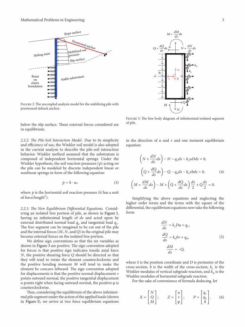
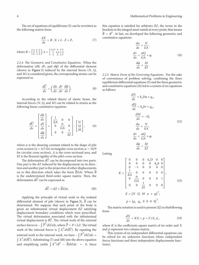
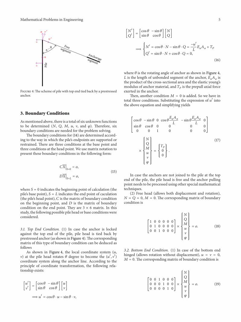
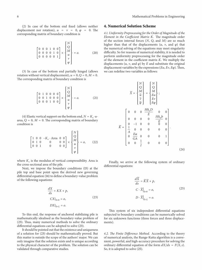
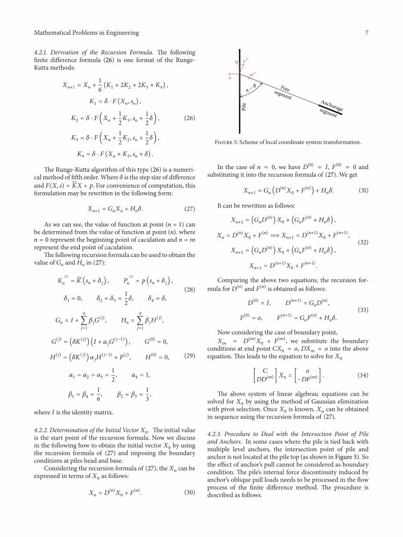
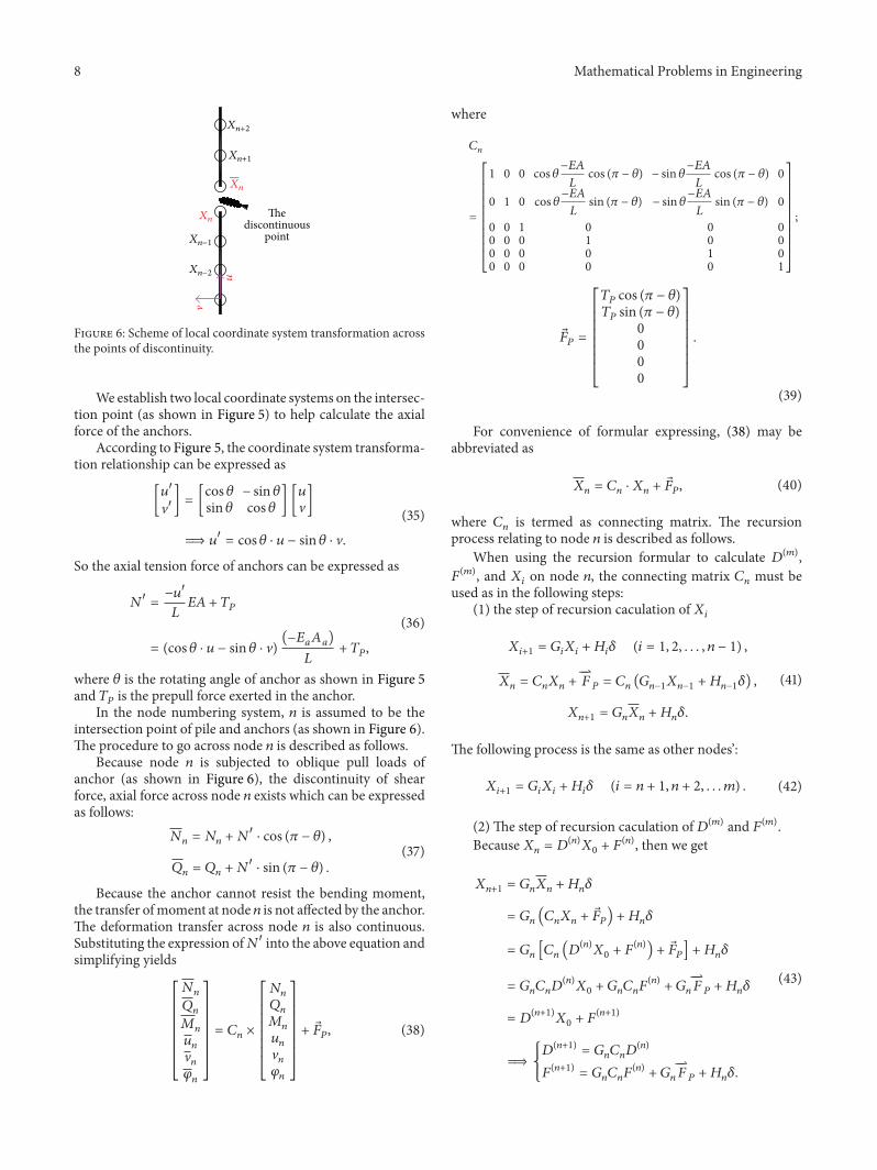
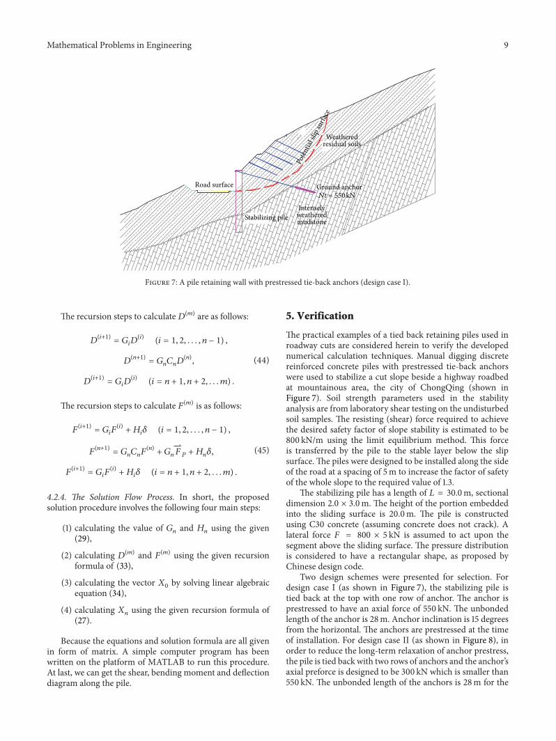
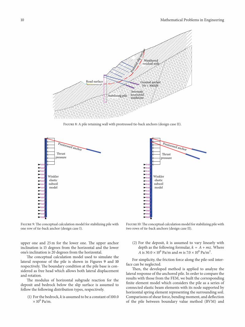
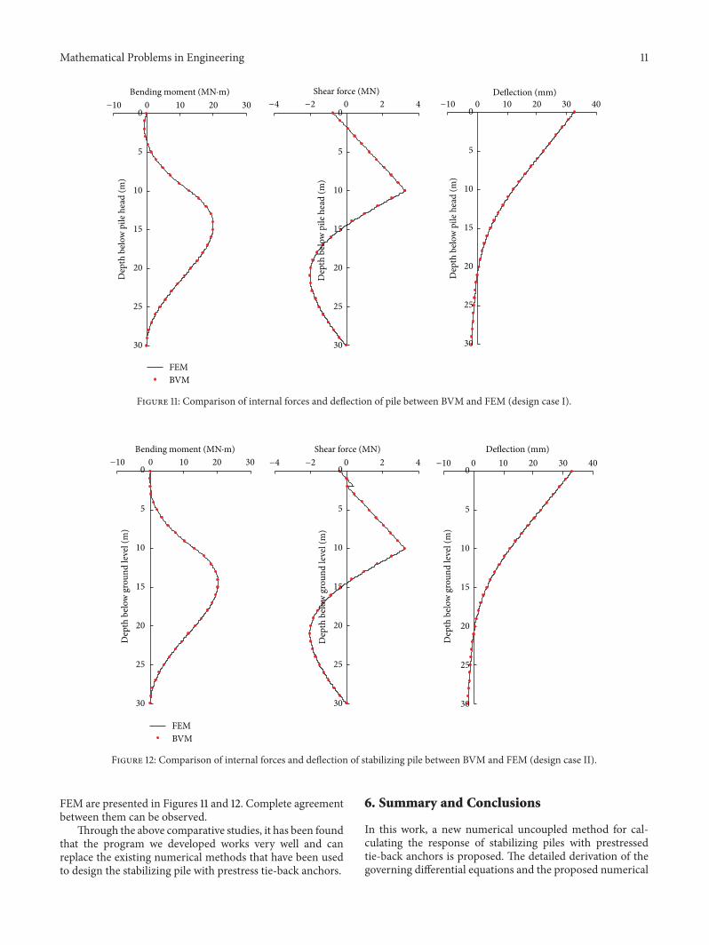
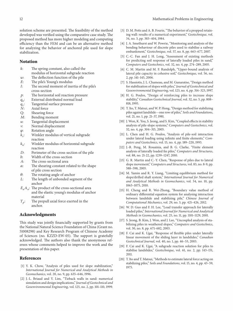