Embed Size (px)
Citation preview
Hindawi Publishing CorporationInternational Journal of Biomedical ImagingVolume 2013, Article ID 152920, 7 pageshttp://dx.doi.org/10.1155/2013/152920
Research ArticleMeasurement of Intervertebral CervicalMotion by Means of Dynamic X-Ray Image Processingand Data Interpolation
Paolo Bifulco, Mario Cesarelli, Maria Romano, Antonio Fratini, and Mario Sansone
Department of Electrical Engineering and Information Technologies (DIETI), University of Naples “Federico II,” Via Claudio 21,80125 Naples, Italy
Correspondence should be addressed to Mario Cesarelli; [email protected]
Received 7 August 2013; Accepted 26 September 2013
Academic Editor: J. C. Chen
Copyright © 2013 Paolo Bifulco et al. This is an open access article distributed under the Creative Commons Attribution License,which permits unrestricted use, distribution, and reproduction in any medium, provided the original work is properly cited.
Accurate measurement of intervertebral kinematics of the cervical spine can support the diagnosis of widespread diseases relatedto neck pain, such as chronic whiplash dysfunction, arthritis, and segmental degeneration. The natural inaccessibility of the spine,its complex anatomy, and the small range of motion only permit concise measurement in vivo. Low dose X-ray fluoroscopyallows time-continuous screening of cervical spine during patient’s spontaneousmotion. To obtain accuratemotionmeasurements,each vertebra was tracked by means of image processing along a sequence of radiographic images. To obtain a time-continuousrepresentation of motion and to reduce noise in the experimental data, smoothing spline interpolation was used. Estimation ofintervertebral motion for cervical segments was obtained by processing patient’s fluoroscopic sequence; intervertebral angle anddisplacement and the instantaneous centre of rotation were computed. The RMS value of fitting errors resulted in about 0.2 degreefor rotation and 0.2mm for displacements.
1. Introduction
Neck pain is a common musculoskeletal problem experi-enced by the vastmajority of the population [1, 2]. Alterationsof cervical spine mechanics that compromise the stabilizingmechanisms of the cervical spine (such those originated bychronic whiplash dysfunction [3], arthritis [4, 5], and seg-mental degeneration [6]) can be possible causes of neck pain.
Detection of spinal instability (degenerative or traumatic)is based on accuratemeasurement of intervertebral kinematic[7]. In particular, forward displacement of the vertebraegreater than 3.5mm and angle between adjacent endplatesgreater than 11 degree is regarded as a sign of instability [8]andindication for surgery.
Quantitative measurements of segmental kinematics alsofind use in the evaluation of cervical arthroplasty, assessmentof disc prosthesis, postsurgery followup, and so forth [9–11].
In spite of their paramount importance in clinical appli-cation, accurate measurement of the intervertebral kinematicare hindered by the natural inaccessibility of the spine, the
complexity of its anatomy, and physiology and the extremelysmall range of motion achieved at segmental level.
Although most of the injuries and degenerative patholo-gies of the cervical spine are associated with reducedmobilityand pain, there is no gold standard for the measurement ofthe kinematics of the cervical spine, not even for the meas-urement of its range of motion as a whole. Many tech-niques were proposed to measure spine kinematics [12–15]. These techniques include those radiological (functionalradiography, cine-radiography, stereo radiography, TC, MRI,etc.), those based on external markers motion tracking (elec-trogoniometers, inclinometers, electromagnetic markers, op-tical skin markers, etc.), those ultrasonic, and those invasive(e.g., insertion of rigid markers in the vertebra bones in thecontext of a surgical operation).
The simpler and less invasivemethods (e.g., external goni-ometers, optical markers, etc.) can only provide appropriateinformation about the entire cervical range of motion,but they are unable to accurately assess intervertebral
2 International Journal of Biomedical Imaging
motion (relatively large errors are associated with the slidingbetween skin markers and bones). Despite patient’s radiationexposure, the radiological methods are currently preferredfor many diagnoses. In particular, functional radiography isthe clinical standard to detect segmental instability anddecide whether to perform a surgery. Intervertebral kine-matics measurements are currently based on functionalflexion-extension radiography [16–18]. However, thismethodinvolves the use of few, end-of-range spinal positions, whilein-between intervertebral motion is disregarded.
It is worth mentioning that some authors suggested thatdisc degeneration may lead to abnormal location of inter-vertebral center of rotation while maintaining intervertebraltranslation and rotation within a normal range [16, 19, 20].Other studies [21, 22] supported that the center of rotationis the most sensitive and specific measurement for detectingdamage of intervertebral disc and facet joints.
Because of the indirect methodology and the physicianmanual selection on radiographies, intervertebral kinematicmeasurements suffer from large inaccuracy. This is particu-larly true for the estimation of center of rotation because smallerrors in vertebra location result in much larger errors on theestimation of the center of rotation.
This study proposes a methodology for measuring thecervical intervertebral kinematics based on the processing ofdynamic X-ray images able to provide objective measure-ments and a continuous description of spontaneous patientmotion.
X-ray fluoroscopy can allow time-continuous screeningof cervical vertebrae during spontaneous neck flexion exten-sion. Fluoroscopy is based on high-gain image intensifiers tostrongly reduce the X-ray radiation dose and allow prolongedrecording, but it produces images with a much poorer SNRthan conventional radiography. The position and orientationof each cervical vertebra were estimated frame by frame ofthe fluoroscopy sequence by means of an opportune time-varying image processing. The intervertebral kinematics wasthen estimated by combining the trajectories of two adjacentvertebrae. Clinically, relevant concise measurements werealso computed as well as the trajectories of the instantaneouscentre of rotation. Motion data were interpolated and filteredwith nonfitting splines to obtain a time-continuous descrip-tion of the joint kinematics. Approximation error analysiswasalso performed.
2. Materials and Methods
A 9-inche digital fluoroscopy device (Stenoscop, GE MedicalSystems) was used for in vivo measurement. The X-ray tubeparameters were adjusted for each subject; on average, theywere set to 1mAs and 50 kVp; the acquisition frame ratewas set to 4 frame/sec; the focus-plane length was about1m. Digital radiological frames were acquired directly fromthe fluoroscopy device. Each image is memorized as rawimage format (uncompressed), it is formed by 576 pixels, andluminance is encoded with 256 levels of gray, and the pixelsize is 0.45 by 0.45mm. The C-arm was set in horizontal
position and the subject was put in, with his neck as closeas possible to the image intensifier. Subjects were fastenedto an adjustable-height chair by apposite belts in orderto obtain shoulder stabilization. Subjects were instructedto spontaneously perform the maximum possible flexion-extension movement of their neck. Before recording, thesubject became familiar with the assigned task in order toperform it correctly and enough slowly. The entire flexion-extension movement was performed in about 30 seconds. Acalibration phantom was used to test for geometrical distor-tions and to measure image noise at different gray-levels.
Since vertebra registration is mainly based on matchingof bones edges (a derivation operation is required on theimages), noise reduction of the fluoroscopic images is ofparamount importance.
In fluoroscopy, the numbers of X-ray photons are stronglyreduced to keep patient’s radiation dose acceptably low. Thelimited availability of photons per pixel generates the so-called quantum noise. Quantum noise is by far the mostdominant noise in fluoroscopic images [23]. Quantum noiseis a signal-dependent Poisson-distributed noise source [24],and its strength varies over the image depending on the localgrey-level intensity. This noise cannot be considered spaceinvariant, additive, Gaussian, and white.
An accurate noise model [25], considering Poisson’s dis-tribution, was held to quantitativelymeasure the fluoroscopicimage noise. Preliminary, the relationship between noisevariance and mean pixel intensity relative to the fluoroscopydevice setup was estimated. Then, the fluoroscopy sequenceswere preprocessed by using an edge-preserving, adaptiveaverage filter that incorporate the information of noise vari-ance versus grey intensity [26]. By holding this information,noise suppression can be exclusively performed by averagingthe only local data that have high probability to be includedin the noise statistics. Filter operates both in space and time,preserving edges and motion [26].
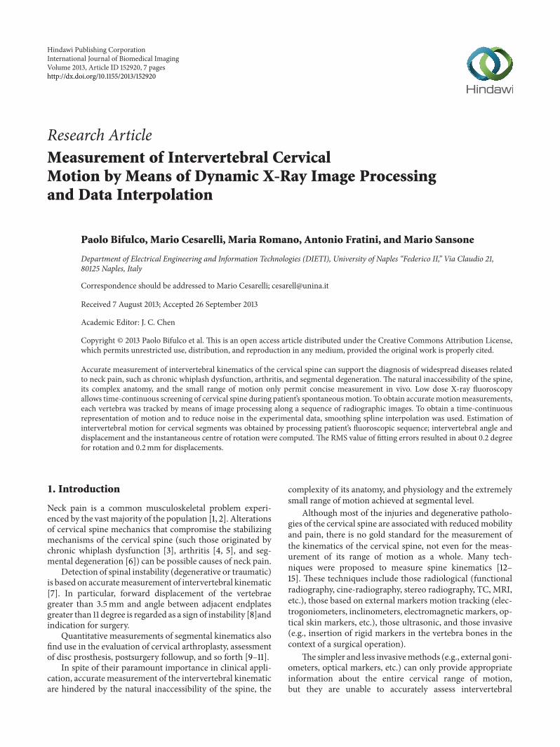
Vertebra tracking was achieved by image templatematch-ing [27, 28]. Cervical vertebrae were assumed to be rigid andthe analysis was limited to the sagittal plane [29, 30] (seeFigure 1).
A template of each cervical vertebra was chosen byselecting portion of the vertebra projection that does notsuperimpose with adjacent vertebra along with the whole thepatient’s motion. In particular, the cervical vertebra templateincluded the anterior vertebral body cortex and the spino-laminar junction particularly visible on the radiographicprojection of spinous process (the area of the facet jointswas excluded). The inclusion of the posterior process in thetemplate (in contrast with lumbar spine tracking [26], whereonly the vertebral body was considered) makes the error invertebra positioning lower.
Vertebra tracking was achieved by matching the prese-lected vertebra template opportunely displaced and rotatedon each of the image of the fluoroscopic sequence [31, 32].
The template matching was based on a particular imagesimilarity index (GNCC), which combines the normalizedcross-correlations of the horizontal and vertical gradients
International Journal of Biomedical Imaging 3
(a) (b)
Figure 1: A prefiltered image of a fluoroscopic sequence (a) and the correspondent gradient image (b).
of the fluoroscopic image. The GNCC index was obtainedaccording to the following formula:
GNCC (𝑖, 𝑗)
=1
2⋅∑(𝑥,𝑦)∈𝑇 𝑔𝑥 (𝑖 + 𝑥, 𝑗 + 𝑦) ⋅ 𝑡𝑥 (𝑥, 𝑦)
√∑(𝑥,𝑦)∈𝑇 𝑔2𝑥 (𝑖 + 𝑥, 𝑗 + 𝑦) ⋅ √∑(𝑥,𝑦)∈𝑇 𝑡
2𝑥 (𝑥, 𝑦)
+1
2⋅∑(𝑥,𝑦)∈𝑇 𝑔𝑦 (𝑖 + 𝑥, 𝑗 + 𝑦) ⋅ 𝑡𝑦 (𝑥, 𝑦)
√∑(𝑥,𝑦)∈𝑇 𝑔2𝑦 (𝑖 + 𝑥, 𝑗 + 𝑦) ⋅ √∑(𝑥,𝑦)∈𝑇 𝑡
2𝑦 (𝑥, 𝑦),
(1)
where 𝑔𝑥 and 𝑔𝑦 are the components of the gradient vectorin the horizontal and vertical directions of a generic fluoro-scopic image and 𝑡𝑥 and 𝑡𝑦 are the components of the gradientvector relative to the template; the summations are extendedto the only pixels, of coordinates (𝑥, 𝑦), belonging to thetemplate. It is worth noting that this expression for the cross-correlation index not only takes into account the product ofthe gradient magnitudes but also performs a scalar productbetween the gradient vectors. This improves accuracy ofvertebra locationwith respect to the simple normalized cross-correlation image matching.
Since each vertebra can be spatially translated and rotatedin between two fluoroscopic images, the maximum of theGNCC index was searched in the three parameter spaces:x-displacement, y-displacement, and rotation angle. Thiswas obtained by progressively rotating the template with0.1 degree increments and repeatedly computing the GNCCindex. The coordinates of the global maximum of the GNCCindex estimate the template displacement, while the anglecorresponding to that maximum is held as the templaterotation. Furthermore, 2D cubic interpolation of the GNCCfunction provided a subpixel accuracy for the vertebra dis-placement.
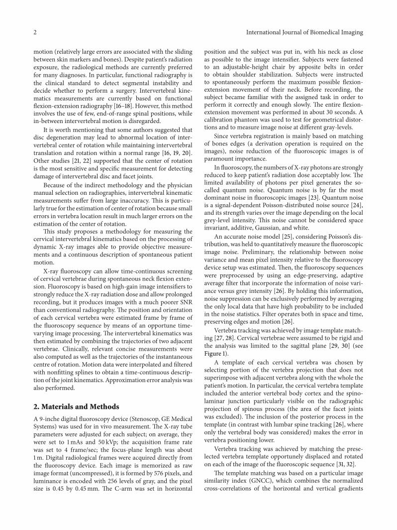
At the end of the vertebra tracking procedure, theestimated x- and y-displacements and angles of rotationof a selected vertebra are available for all the frames ofthe fluoroscopic sequence. These three parameters, over
Figure 2: Absolute trajectories of vertebrae during flexion-exten-sion.
time, completely describe the planar, rigid motion (i.e., thetrajectory) of each cervical vertebra (see Figure 2).
From these data, the intervertebral description of motionwas obtained, that is, the trajectory of the upper vertebra withrespect to the lower vertebra considered motionless.
In particular, the intervertebral angle of rotation 𝛼𝐼𝑉 wasgiven by
𝛼𝐼𝑉 = 𝛼𝑈𝑉 − 𝛼𝐿𝑉 (2)
and the intervertebral displacements (𝑥𝐼𝑉, 𝑦𝐼𝑉)were given by
(𝑥𝐼𝑉𝑦𝐼𝑉) = (
cos (−𝛼𝐿𝑉) − sin (−𝛼𝐿𝑉)sin (−𝛼𝐿𝑉) cos (−𝛼𝐿𝑉)
) ⋅ (𝑥𝑈𝑉 − 𝑥𝐿𝑉𝑦𝑈𝑉 − 𝑦𝐿𝑉
) ,
(3)
where 𝛼𝑈𝑉 is the angle of rotation of the upper vertebra, 𝛼𝐿𝑉is the rotation of the lower vertebra, (𝑥𝑈𝑉, 𝑦𝑈𝑉) are the x- andy-displacements of the upper vertebra, and (𝑥𝐿𝑉, 𝑦𝐿𝑉) are thex- and y-displacements of the lower vertebra.
The intervertebral discrete-time datawere interpolated byquintic nonfitting spline (similarly to [33]) providing both
4 International Journal of Biomedical Imaging
0 5 10 15 20 25 30
0
2
4
6
8
10
12
14
16
Time (s)
i.v.a.
(deg
)
−2
Intervertebral angle
(a)
0 5 10 15 20 25 3010
15
20
25
0 5 10 15 20 25 3040
45
50
55
Time (s)
x- and y-coord. intervertebral trajectory
x(m
m)
y(m
m)
(b)
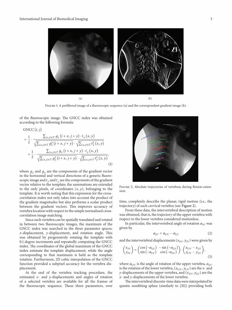
Figure 3: SegmentC5-C6. (a) Intervertebral anglemeasurements (dots) and spline interpolation (cont. line). (b) Intervertebral displacements.
0 5 10 15 20 25 30−5
−4
−3
−2
−1
0
1
2
3Angular velocity
Time (s)
Ang
ular
velo
city
(deg
/s)
(a)
0 5 10 15 20 25 30
2.5
−2.5
2
−2
1.5
−1.5
1
−1
0.5
−0.5
0
Ang
ular
acce
lera
tion
(deg
/s2)
Time (s)
Angular acceleration
(b)
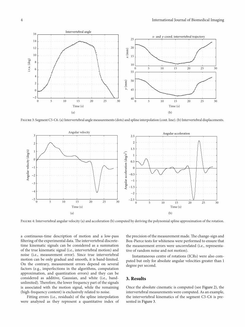
Figure 4: Intervertebral angular velocity (a) and acceleration (b) computed by deriving the polynomial spline approximation of the rotation.
a continuous-time description of motion and a low-passfiltering of the experimental data.The intervertebral discrete-time kinematic signals can be considered as a summationof the true kinematic signal (i.e., intervertebral motion) andnoise (i.e., measurement error). Since true intervertebralmotion can be only gradual and smooth, it is band-limited.On the contrary, measurement errors depend on severalfactors (e.g., imperfections in the algorithms, computationapproximation, and quantization errors) and they can beconsidered as additive, Gaussian, and white (i.e., band-unlimited).Therefore, the lower frequency part of the signalsis associated with the motion signal, while the remaining(high-frequency content) is exclusively related to noise.
Fitting errors (i.e., residuals) of the spline interpolationwere analyzed as they represent a quantitative index of
the precision of themeasurementmade.The change-sign andBox-Pierce tests for whiteness were performed to ensure thatthe measurement errors were uncorrelated (i.e., representa-tive of random noise and not motion).
Instantaneous centre of rotations (ICRs) were also com-puted but only for absolute angular velocities greater than 1degree per second.
3. Results
Once the absolute cinematic is computed (see Figure 2), theintervertebral measurements were computed. As an example,the intervertebral kinematics of the segment C5-C6 is pre-sented in Figure 3.
International Journal of Biomedical Imaging 5
0 5 10 15 20 25 30
0
1
Time (s)
−1
−0.8
−0.6
−0.4
−0.2
0.2
0.4
0.6
0.8
(deg
)
Spline fitting errors of intervertebral angles
RMS = 0.18 deg
(a)
0 5 10 15 20 25 30−0.8
−0.6
−0.4
−0.2
0
0.2
0.4
0.6
0.8Spline fitting errors of x-displacement
(mm
)
RMS =
Time (s)
0.15mm
(b)
0 5 10 15 20 25 30−0.8
−0.6
−0.4
−0.2
0
0.2
0.4
0.6
0.8
(mm
)
Time (s)
Spline fitting errors of y-displacement
RMS = 0.14mm
(c)
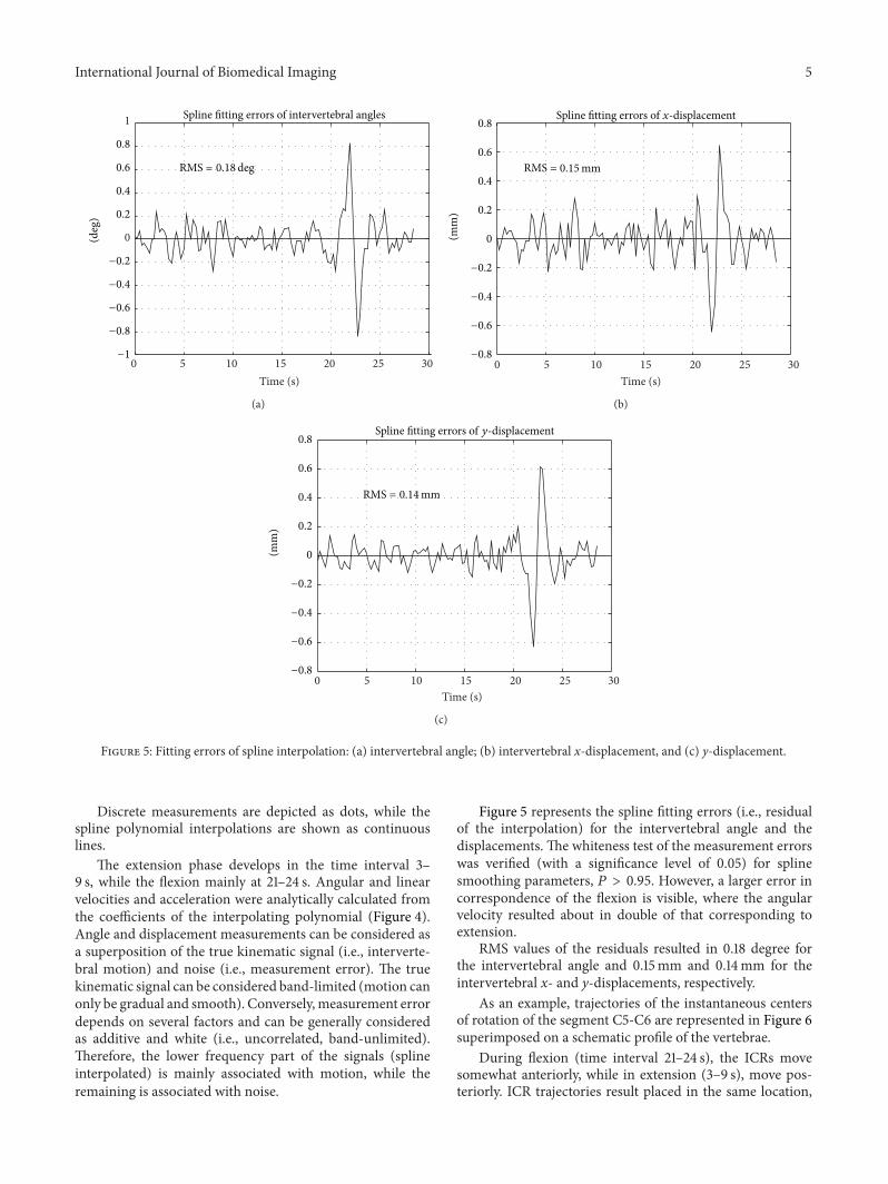
Figure 5: Fitting errors of spline interpolation: (a) intervertebral angle; (b) intervertebral x-displacement, and (c) y-displacement.
Discrete measurements are depicted as dots, while thespline polynomial interpolations are shown as continuouslines.
The extension phase develops in the time interval 3–9 s, while the flexion mainly at 21–24 s. Angular and linearvelocities and acceleration were analytically calculated fromthe coefficients of the interpolating polynomial (Figure 4).Angle and displacement measurements can be considered asa superposition of the true kinematic signal (i.e., interverte-bral motion) and noise (i.e., measurement error). The truekinematic signal can be considered band-limited (motion canonly be gradual and smooth). Conversely,measurement errordepends on several factors and can be generally consideredas additive and white (i.e., uncorrelated, band-unlimited).Therefore, the lower frequency part of the signals (splineinterpolated) is mainly associated with motion, while theremaining is associated with noise.
Figure 5 represents the spline fitting errors (i.e., residualof the interpolation) for the intervertebral angle and thedisplacements. The whiteness test of the measurement errorswas verified (with a significance level of 0.05) for splinesmoothing parameters, 𝑃 > 0.95. However, a larger error incorrespondence of the flexion is visible, where the angularvelocity resulted about in double of that corresponding toextension.
RMS values of the residuals resulted in 0.18 degree forthe intervertebral angle and 0.15mm and 0.14mm for theintervertebral x- and y-displacements, respectively.
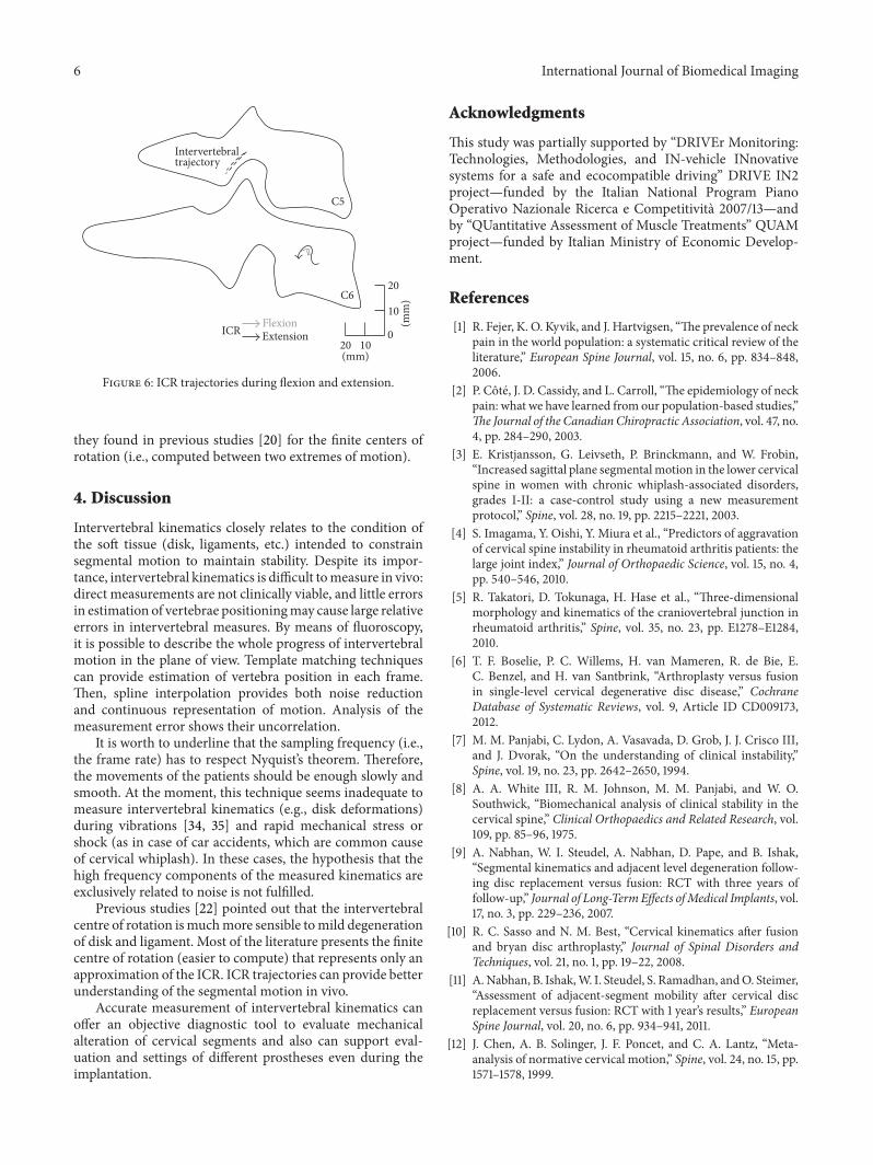
As an example, trajectories of the instantaneous centersof rotation of the segment C5-C6 are represented in Figure 6superimposed on a schematic profile of the vertebrae.
During flexion (time interval 21–24 s), the ICRs movesomewhat anteriorly, while in extension (3–9 s), move pos-teriorly. ICR trajectories result placed in the same location,
6 International Journal of Biomedical Imaging
10
20
01020
(mm)
(mm
)C6
C5
FlexionExtensionICR
Intervertebraltrajectory
Figure 6: ICR trajectories during flexion and extension.
they found in previous studies [20] for the finite centers ofrotation (i.e., computed between two extremes of motion).
4. Discussion
Intervertebral kinematics closely relates to the condition ofthe soft tissue (disk, ligaments, etc.) intended to constrainsegmental motion to maintain stability. Despite its impor-tance, intervertebral kinematics is difficult tomeasure in vivo:direct measurements are not clinically viable, and little errorsin estimation of vertebrae positioningmay cause large relativeerrors in intervertebral measures. By means of fluoroscopy,it is possible to describe the whole progress of intervertebralmotion in the plane of view. Template matching techniquescan provide estimation of vertebra position in each frame.Then, spline interpolation provides both noise reductionand continuous representation of motion. Analysis of themeasurement error shows their uncorrelation.
It is worth to underline that the sampling frequency (i.e.,the frame rate) has to respect Nyquist’s theorem. Therefore,the movements of the patients should be enough slowly andsmooth. At the moment, this technique seems inadequate tomeasure intervertebral kinematics (e.g., disk deformations)during vibrations [34, 35] and rapid mechanical stress orshock (as in case of car accidents, which are common causeof cervical whiplash). In these cases, the hypothesis that thehigh frequency components of the measured kinematics areexclusively related to noise is not fulfilled.
Previous studies [22] pointed out that the intervertebralcentre of rotation ismuchmore sensible tomild degenerationof disk and ligament. Most of the literature presents the finitecentre of rotation (easier to compute) that represents only anapproximation of the ICR. ICR trajectories can provide betterunderstanding of the segmental motion in vivo.
Accurate measurement of intervertebral kinematics canoffer an objective diagnostic tool to evaluate mechanicalalteration of cervical segments and also can support eval-uation and settings of different prostheses even during theimplantation.
Acknowledgments
This study was partially supported by “DRIVEr Monitoring:Technologies, Methodologies, and IN-vehicle INnovativesystems for a safe and ecocompatible driving” DRIVE IN2project—funded by the Italian National Program PianoOperativo Nazionale Ricerca e Competitivita 2007/13—andby “QUantitative Assessment of Muscle Treatments” QUAMproject—funded by Italian Ministry of Economic Develop-ment.
References
[1] R. Fejer, K. O. Kyvik, and J. Hartvigsen, “The prevalence of neckpain in the world population: a systematic critical review of theliterature,” European Spine Journal, vol. 15, no. 6, pp. 834–848,2006.
[2] P. Cote, J. D. Cassidy, and L. Carroll, “The epidemiology of neckpain: what we have learned from our population-based studies,”The Journal of the Canadian Chiropractic Association, vol. 47, no.4, pp. 284–290, 2003.
[3] E. Kristjansson, G. Leivseth, P. Brinckmann, and W. Frobin,“Increased sagittal plane segmentalmotion in the lower cervicalspine in women with chronic whiplash-associated disorders,grades I-II: a case-control study using a new measurementprotocol,” Spine, vol. 28, no. 19, pp. 2215–2221, 2003.
[4] S. Imagama, Y. Oishi, Y. Miura et al., “Predictors of aggravationof cervical spine instability in rheumatoid arthritis patients: thelarge joint index,” Journal of Orthopaedic Science, vol. 15, no. 4,pp. 540–546, 2010.
[5] R. Takatori, D. Tokunaga, H. Hase et al., “Three-dimensionalmorphology and kinematics of the craniovertebral junction inrheumatoid arthritis,” Spine, vol. 35, no. 23, pp. E1278–E1284,2010.
[6] T. F. Boselie, P. C. Willems, H. van Mameren, R. de Bie, E.C. Benzel, and H. van Santbrink, “Arthroplasty versus fusionin single-level cervical degenerative disc disease,” CochraneDatabase of Systematic Reviews, vol. 9, Article ID CD009173,2012.
[7] M. M. Panjabi, C. Lydon, A. Vasavada, D. Grob, J. J. Crisco III,and J. Dvorak, “On the understanding of clinical instability,”Spine, vol. 19, no. 23, pp. 2642–2650, 1994.
[8] A. A. White III, R. M. Johnson, M. M. Panjabi, and W. O.Southwick, “Biomechanical analysis of clinical stability in thecervical spine,” Clinical Orthopaedics and Related Research, vol.109, pp. 85–96, 1975.
[9] A. Nabhan, W. I. Steudel, A. Nabhan, D. Pape, and B. Ishak,“Segmental kinematics and adjacent level degeneration follow-ing disc replacement versus fusion: RCT with three years offollow-up,” Journal of Long-TermEffects ofMedical Implants, vol.17, no. 3, pp. 229–236, 2007.
[10] R. C. Sasso and N. M. Best, “Cervical kinematics after fusionand bryan disc arthroplasty,” Journal of Spinal Disorders andTechniques, vol. 21, no. 1, pp. 19–22, 2008.
[11] A.Nabhan, B. Ishak,W. I. Steudel, S. Ramadhan, andO. Steimer,“Assessment of adjacent-segment mobility after cervical discreplacement versus fusion: RCT with 1 year’s results,” EuropeanSpine Journal, vol. 20, no. 6, pp. 934–941, 2011.
[12] J. Chen, A. B. Solinger, J. F. Poncet, and C. A. Lantz, “Meta-analysis of normative cervical motion,” Spine, vol. 24, no. 15, pp.1571–1578, 1999.
International Journal of Biomedical Imaging 7
[13] K. Jordan, “Assessment of published reliability studies forcervical spine range-of-motion measurement tools,” Journal ofManipulative and Physiological Therapeutics, vol. 23, no. 3, pp.180–195, 2000.
[14] F. Antonaci, S. Ghirmai, G. Bono, andG. Nappi, “Currentmeth-ods for cervical spine movement evaluation: a review,” Clinicaland Experimental Rheumatology, vol. 18, no. 2, supplement 19,pp. S45–S52, 2000.
[15] T. Prushansky and Z. Dvir, “Cervical motion testing: method-ology and clinical implications,” Journal of Manipulative andPhysiological Therapeutics, vol. 31, no. 7, pp. 503–508, 2008.
[16] J. Dimnet, A. Pasquet,M. H. Krag, andM.M. Panjabi, “Cervicalspine motion in the sagittal plane: kinematic and geometricparameters,” Journal of Biomechanics, vol. 15, no. 12, pp. 959–969, 1982.
[17] A. Leone, G. Guglielmi, V. N. Cassar-Pullicino, and L. Bonomo,“Lumbar intervertebral instability: a review,”Radiology, vol. 245,no. 1, pp. 62–77, 2007.
[18] T. Maeda, T. Ueta, E. Mori et al., “Soft-tissue damage andsegmental instability in adult patients with cervical spinal cordinjury without major bone injury,” Spine, vol. 37, no. 25, pp.E1560–E1566, 2012.
[19] S.-W. Lee, E. R. C. Draper, and S. P. F. Hughes, “Instantaneouscenter of rotation and instability of the cervical spine: a clinicalstudy,” Spine, vol. 22, no. 6, pp. 641–648, 1997.
[20] H. van Mameren, H. Sanches, J. Beursgens, and J. Drukker,“Cervical spine motion in the sagittal plane II: position ofsegmental averaged instantaneous centers of rotation—a cin-eradiographic study,” Spine, vol. 17, no. 5, pp. 467–474, 1992.
[21] T. Brown, C. A. Reitman, L. Nguyen, and J. A. Hipp, “Inter-vertebral motion after incremental damage to the posteriorstructures of the cervical spine,” Spine, vol. 30, no. 17, pp. E503–508, 2005.
[22] H. Hwang, J. A. Hipp, P. Ben-Galim, and C. A. Reitman,“Threshold cervical range-of-motion necessary to detect abnor-mal intervertebral motion in cervical spine radiographs,” Spine,vol. 33, no. 8, pp. E261–E267, 2008.
[23] M. J. Tapiovaara, “SNR and noise measurements for medicalimaging: II. Application to fluoroscopic x-ray equipment,”Physics in Medicine and Biology, vol. 38, no. 12, pp. 1761–1788,1993.
[24] L. C. Chan, K. A. Katsaggelos, and V. A. Sahakian, “Imagesequence filtering in quantum limited noise with applications tolow-dose fluoroscopy,” IEEE Transactions on Medical Imaging,vol. 12, no. 3, pp. 610–621, 1993.
[25] M. Cesarelli, P. Bifulco, T. Cerciello, M. Romano, and L. Paura,“X-ray fluoroscopy noise modeling for filter design,” Interna-tional Journal of Computer Assisted Radiology and Surgery, vol.8, no. 2, pp. 269–278, 2013.
[26] T. Cerciello, P. Bifulco, M. Cesarelli, and A. Fratini, “A com-parison of denoising methods for X-ray fluoroscopic images,”Biomedical Signal Processing and Control, vol. 7, no. 6, pp. 550–559, 2012.
[27] G. P. Penney, J. Weese, J. A. Little, P. Desmedt, D. L. G. Hill, andD. J. Hawkes, “A comparison of similarity measures for usein 2-D-3-D medical image registration,” IEEE Transactions onMedical Imaging, vol. 17, no. 4, pp. 586–595, 1998.
[28] J.Wu,M.Kim, J. Peters,H.Chung, and S. S. Samant, “Evaluationof similarity measures for use in the intensity-based rigid 2D-3D registration for patient positioning in radiotherapy,”MedicalPhysics, vol. 36, no. 12, pp. 5391–5403, 2009.
[29] P. Bifulco, M. Sansone, M. Cesarelli, R. Allen, and M. Bracale,“Estimation of out-of-plane vertebra rotations on radiographicprojections using CT data: a simulation study,” Medical Engi-neering and Physics, vol. 24, no. 4, pp. 295–300, 2002.
[30] P. Bifulco, M. Cesarelli, R. Allen, M. Romano, A. Fratini, andG. Pasquariello, “2D-3D registration of CT vertebra volumeto fluoroscopy projection: a calibration model assessment,”EURASIP Journal on Advances in Signal Processing, vol. 2010,Article ID 806094, 2010.
[31] P. Bifulco, M. Cesarelli, R. Allen, M. Sansone, and M. Bracale,“Automatic recognition of vertebral landmarks in fluoroscopicsequences for analysis of intervertebral kinematics,” Medicaland Biological Engineering and Computing, vol. 39, no. 1, pp. 65–75, 2001.
[32] T. Cerciello, M. Romano, P. Bifulco, M. Cesarelli, and R. Allen,“Advanced template matching method for estimation of inter-vertebral kinematics of lumbar spine,”Medical Engineering andPhysics, vol. 33, no. 10, pp. 1293–1302, 2011.
[33] P. Bifulco, M. Cesarelli, T. Cerciello, and M. Romano, “A con-tinuous description of intervertebral motion by means of splineinterpolation of kinematic data extracted by videofluoroscopy,”Journal of Biomechanics, vol. 45, no. 4, pp. 634–641, 2012.
[34] A. Fratini, A. la Gatta, P. Bifulco, M. Romano, and M. Cesarelli,“Muscle motion and EMG activity in vibration treatment,”Medical Engineering and Physics, vol. 31, no. 9, pp. 1166–1172,2009.
[35] M. Cesarelli, A. Fratini, P. Bifulco, A. la Gatta, M. Romano,andG. Pasquariello, “Analysis andmodelling ofmusclesmotionduring whole body vibration,” EURASIP Journal on Advances inSignal Processing, vol. 2010, Article ID 972353, 2010.

International Journal of
AerospaceEngineeringHindawi Publishing Corporationhttp://www.hindawi.com Volume 2014
RoboticsJournal of
Hindawi Publishing Corporationhttp://www.hindawi.com Volume 2014
Hindawi Publishing Corporationhttp://www.hindawi.com Volume 2014
Active and Passive Electronic Components
Control Scienceand Engineering
Journal of
Hindawi Publishing Corporationhttp://www.hindawi.com Volume 2014
International Journal of
RotatingMachinery
Hindawi Publishing Corporationhttp://www.hindawi.com Volume 2014
Hindawi Publishing Corporation http://www.hindawi.com
Journal ofEngineeringVolume 2014
Submit your manuscripts athttp://www.hindawi.com
VLSI Design
Hindawi Publishing Corporationhttp://www.hindawi.com Volume 2014
Hindawi Publishing Corporationhttp://www.hindawi.com Volume 2014
Shock and Vibration
Hindawi Publishing Corporationhttp://www.hindawi.com Volume 2014
Civil EngineeringAdvances in
Acoustics and VibrationAdvances in
Hindawi Publishing Corporationhttp://www.hindawi.com Volume 2014
Hindawi Publishing Corporationhttp://www.hindawi.com Volume 2014
Electrical and Computer Engineering
Journal of
Advances inOptoElectronics
Hindawi Publishing Corporation http://www.hindawi.com
Volume 2014
The Scientific World JournalHindawi Publishing Corporation http://www.hindawi.com Volume 2014
SensorsJournal of
Hindawi Publishing Corporationhttp://www.hindawi.com Volume 2014
Modelling & Simulation in EngineeringHindawi Publishing Corporation http://www.hindawi.com Volume 2014
Hindawi Publishing Corporationhttp://www.hindawi.com Volume 2014
Chemical EngineeringInternational Journal of Antennas and
Propagation
International Journal of
Hindawi Publishing Corporationhttp://www.hindawi.com Volume 2014
Hindawi Publishing Corporationhttp://www.hindawi.com Volume 2014
Navigation and Observation
International Journal of
Hindawi Publishing Corporationhttp://www.hindawi.com Volume 2014
DistributedSensor Networks
International Journal of


![Radiographic anatomy of the intervertebral cervical and ... · plexus and fed by the radiculomedullary arteries described above [1,2]. Accordingly, we distinguish an anterior spinal](https://img.pdfslide.us/doc/110x75/6065e8466e3b423054551e49/radiographic-anatomy-of-the-intervertebral-cervical-and-plexus-and-fed-by-the.jpg)