Embed Size (px)
Citation preview

Research ArticleGrafting of Gold Nanoparticles onGlass Using Sputtered Gold Interlayers
Ondlej Kvítek,1 Robin Hendrych,1 Zde^ka Kolská,2 and Václav ŠvorIík1
1 Department of Solid State Engineering, Institute of Chemical Technology, 166 28 Prague, Czech Republic2 Faculty of Science, J. E. Purkyne University, 400 96 Usti nad Labem, Czech Republic
Correspondence should be addressed to Ondrej Kvıtek; [email protected]
Received 13 November 2013; Accepted 12 May 2014; Published 16 June 2014
Academic Editor: Concha Gimeno
Copyright © 2014 Ondrej Kvıtek et al. This is an open access article distributed under the Creative Commons Attribution License,which permits unrestricted use, distribution, and reproduction in any medium, provided the original work is properly cited.
Three-step preparation of nanostructured Au layer on glass substrate is described. The procedure starts with sputtered goldinterlayer, followed by grafting with dithiols and final coverage with gold nanoparticles (AuNPs). Successful binding of dithiolson the sputtered Au film was confirmed by X-ray photoelectron spectroscopy measurement. AuNPs bound to the surface wereobserved using atomic force microscopy. Both single nanoparticles and their aggregates were observed. UV-Vis spectra showbroadening of surface plasmon resonance peak after AuNPs binding caused by aggregation of AuNPs on the sample surface. Zetapotential measurements suggest that a large part of the dithiol molecules are preferentially bound to the gold interlayer via both–SH groups.
1. Introduction
Controlled formation of metal nanostructures on solid sur-faces is being very extensively studied. Isolated nanoparticlesbound to flat surfaces show properties that are very differentfrom bulk material. The specific properties make nanopar-ticles promising for applications in many different areassuch as microelectronics, optoelectronics [1], preparation ofbiosensor devices, or medicine [2–4]. In modern analyticalmethods, surface-enhanced Raman scattering and surfaceplasmon resonance (SPR) sensing (both using nanostruc-tured metal surfaces) draw great attention. Various methodswere employed to prepare suitable nanostructures. Treatmentof the substrate surface with different agents with the aimof improving its reactivity for subsequent modification byvarious organic compounds followed by coating with goldnanoparticles (AuNPs) has been investigated [5, 6]. Anotherapproach is to modify the surface of the particles themselvesto facilitate their interaction with substrates [7]. Sputtering,thermal, and e-beam evaporationmethods of thin filmprepa-ration combinedwith postdeposition thermal treatment havebeen used to fabricate nanoisland-like structure of Au on
substrates [8, 9]. Other methods comprise forming of self-assembled monolayers [10] or laser ablation/gas deposition[11].
This work focuses on binding of AuNPs on smoothAu layer rather than structuring the thin gold layer itself(Figure 1). For potential applications, uniformity of AuNPscoverage over the substrate surface is very important. Accord-ing to some previous studies smooth Au surfaces can becovered with highly organized structures of reactive organiccompounds like dithiols. The surface treated in this waymay facilitate subsequent grafting with AuNPs. In this studyoctane-1,8-dithiol with two –SH groups inmolecule is used tomediate binding of AuNPs to underlying gold layer depositedon glass substrate. The resulting surface structure and itsproperties were characterized by atomic force microscopy(AFM), X-ray photoelectron spectroscopy (XPS), electroki-netic analysis, and UV-Vis spectroscopy.
2. Materials and Methods
Borosilicate microscopic cover glass 15 × 15mm2 supplied byMenzel-Glaser was used as a substrate for deposition. Glass
Hindawi Publishing CorporationJournal of ChemistryVolume 2014, Article ID 450413, 6 pageshttp://dx.doi.org/10.1155/2014/450413
2 Journal of Chemistry
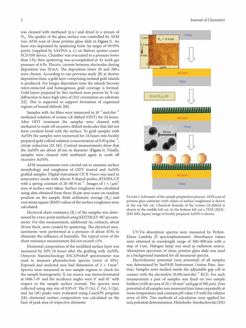
was cleaned with methanol (p.a.) and dried in a stream ofN2. The quality of the glass surface was controlled by AFM
(see AFM scan of clean pristine glass slide in Figure 1). Aulayer was deposited by sputtering from Au target of 99.95%purity (supplied by SAFINA a. s.) on Balzers sputter-coaterSCD 050 device. Chamber was evacuated to a pressure lowerthan 1 Pa; then sputtering was accomplished at Ar work gaspressure of 6 Pa. Electric current between electrodes duringdeposition was 20mA. The deposition times 20 and 200 swere chosen. According to our previous study [8] at shorterdeposition time, a gold layer comprising isolated gold islandsis produced. For longer deposition time the islands becomeinterconnected and homogenous gold coverage is formed.Gold layers prepared by this method were proven by X-raydiffraction to have high ratio of (111) orientation on substrate[12]. This is supposed to support formation of organizedregions of bound dithiols [10].
Samples with Au films were immersed in 10−3mol⋅dm−3methanol solution of octane-1,8-dithiol (ODT) for 24 hours.After ODT treatment the samples were cleaned withmethanol to wash off excessive dithiol molecules that did notform covalent bond with the surface. To graft samples withAuNPs the samples were immersed for 24 hours into freshlyprepared gold colloid solution (concentration of 0.05 g⋅dm−3,citrate reduction [13, 14]). Control measurements show thatthe AuNPs are about 20 nm in diameter (Figure 1). Finally,samples were cleaned with methanol again to wash offexcessive AuNPs.
AFM measurements were carried out to examine surfacemorphology and roughness of ODT treated and AuNPsgrafted samples. Digital instrument CP II Veeco was used innoncontact mode with silicon P-doped probes RTESPA-CPwith a spring constant of 20–80N⋅m−1. Images of 1 × 1 𝜇m2area of surface were taken. Surface roughness was calculatedusing data obtained from three 10 𝜇m area scans on randomposition on the sample. Both arithmetic average (Ra) androotmean square (RMS) values of the surface roughness werecalculated.
Electrical sheet resistance (Rs) of the samples was deter-mined by a two-pointmethod using KEITHLEY 487 picoam-meter. For this measurement, additional Au contacts, about50 nm thick, were created by sputtering. The electrical mea-surements were performed at a pressure of about 10 Pa toeliminate the influence of humidity. The typical error of thesheet resistance measurement did not exceed ±5%.
Elemental composition of the modified surface layer wasmeasured by XPS 24 hours after the grafting with AuNPs.Omicron Nanotechnology ESCAProbeP spectrometer wasused to measure photoelectron spectra (error of 10%).Exposed and analyzed area had dimension of 2 × 3mm2.Spectra were measured in two sample regions to check forthe sample homogeneity. X-ray source was monochromatedat 1486.7 eV and the incidence angles were 0∘ and 81∘ withrespect to the sample surface normal. The spectra werecollected using step size of 0.05 eV. The O (1s), C (1s), S (2p),and Au (4f) peaks were evaluated using CasaXPS program[14]; elemental surface composition was calculated on thebase of peak area of respective elements.
1𝜇m
1
2.5nm
0nm
00
Ra = 0.4nmGlass
Au layer
Glass
Au layer
Glass
Au layer
Glass
HS (CH2)8 SH
50nm
(𝜇m)
Figure 1: Schematic of the sample preparation process. AFM scan ofpristine glass substrate (with values of surface roughness) is shownin the top left cut. Chemical formula of the octane-1,8-dithiol isshown in the middle left cut. In the bottom left cut a TEM (JEOL-JEM 1010, Japan) image of freshly prepared AuNPs is shown.
UV-Vis absorption spectra were measured by Perkin-Elmer Lambda 25 spectrophotometer. Absorbance valueswere obtained in wavelength range of 300–800 nm with astep of 1 nm. Halogen lamp was used as radiation source.Absorption spectrum of clean, pristine glass slide was usedas a background standard for all measured spectra.
Electrokinetic potential (zeta potential) of all sampleswas determined by SurPASS Instrument (Anton Paar, Aus-tria). Samples were studied inside the adjustable gap cell incontact with the electrolyte (0.001mol⋅dm−3 KCl). For eachmeasurement a pair of samples was fixed on two sampleholders (with an area of 20× 10mm2 and gap of 100𝜇m). Zetapotential of all samples wasmeasured four times repeatedly atroom temperature and constant pH value 5.9 with the relativeerror of 10%. Two methods of calculation were applied forzeta potential determination.Helmholtz-Smoluchowski (HS)
Journal of Chemistry 3
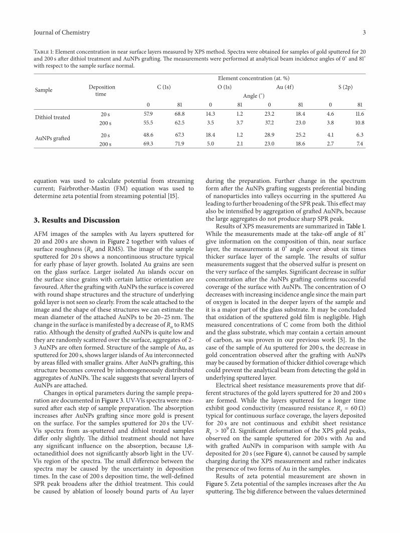
Table 1: Element concentration in near surface layers measured by XPS method. Spectra were obtained for samples of gold sputtered for 20and 200 s after dithiol treatment and AuNPs grafting. The measurements were performed at analytical beam incidence angles of 0∘ and 81∘with respect to the sample surface normal.
Sample Depositiontime
Element concentration (at. %)C (1s) O (1s) Au (4f) S (2p)
Angle (∘)0 81 0 81 0 81 0 81
Dithiol treated 20 s 57.9 68.8 14.3 1.2 23.2 18.4 4.6 11.6200 s 55.5 62.5 3.5 3.7 37.2 23.0 3.8 10.8
AuNPs grafted 20 s 48.6 67.3 18.4 1.2 28.9 25.2 4.1 6.3200 s 69.3 71.9 5.0 2.1 23.0 18.6 2.7 7.4
equation was used to calculate potential from streamingcurrent; Fairbrother-Mastin (FM) equation was used todetermine zeta potential from streaming potential [15].
3. Results and Discussion
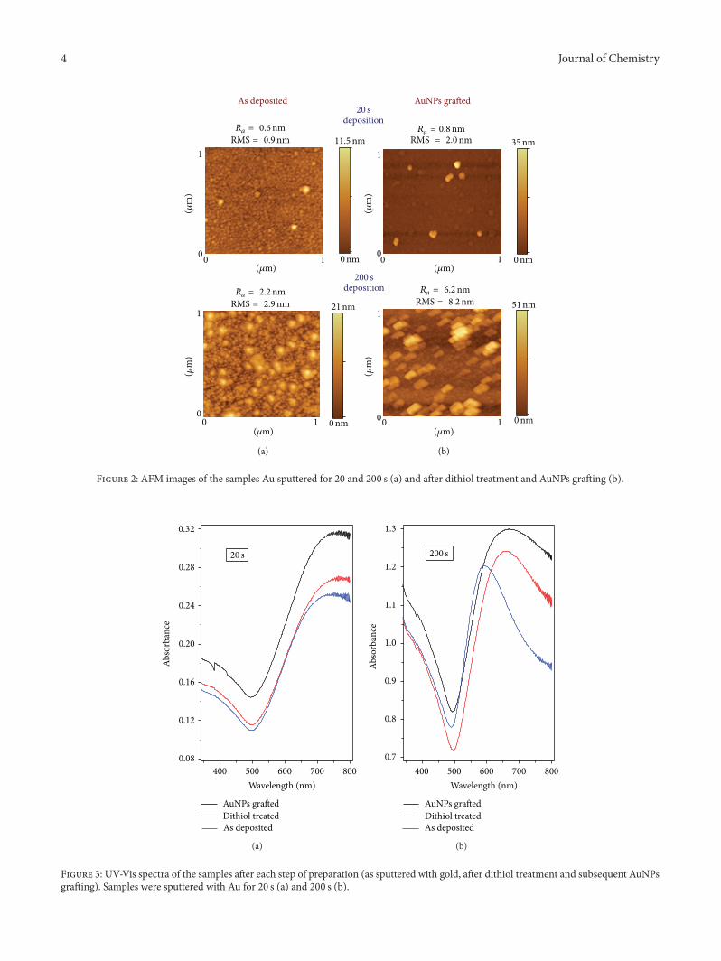
AFM images of the samples with Au layers sputtered for20 and 200 s are shown in Figure 2 together with values ofsurface roughness (Ra and RMS). The image of the samplesputtered for 20 s shows a noncontinuous structure typicalfor early phase of layer growth. Isolated Au grains are seenon the glass surface. Larger isolated Au islands occur onthe surface since grains with certain lattice orientation arefavoured. After the graftingwithAuNPs the surface is coveredwith round shape structures and the structure of underlyinggold layer is not seen so clearly. From the scale attached to theimage and the shape of these structures we can estimate themean diameter of the attached AuNPs to be 20–25 nm. Thechange in the surface ismanifested by a decrease ofRa to RMSratio. Although the density of grafted AuNPs is quite low andthey are randomly scattered over the surface, aggregates of 2-3 AuNPs are often formed. Structure of the sample of Au, assputtered for 200 s, shows larger islands of Au interconnectedby areas filled with smaller grains. After AuNPs grafting, thisstructure becomes covered by inhomogeneously distributedaggregates of AuNPs. The scale suggests that several layers ofAuNPs are attached.
Changes in optical parameters during the sample prepa-ration are documented in Figure 3. UV-Vis spectra weremea-sured after each step of sample preparation. The absorptionincreases after AuNPs grafting since more gold is presenton the surface. For the samples sputtered for 20 s the UV-Vis spectra from as-sputtered and dithiol treated samplesdiffer only slightly. The dithiol treatment should not haveany significant influence on the absorption, because 1,8-octanedithiol does not significantly absorb light in the UV-Vis region of the spectra. The small difference between thespectra may be caused by the uncertainty in depositiontimes. In the case of 200 s deposition time, the well-definedSPR peak broadens after the dithiol treatment. This couldbe caused by ablation of loosely bound parts of Au layer
during the preparation. Further change in the spectrumform after the AuNPs grafting suggests preferential bindingof nanoparticles into valleys occurring in the sputtered Auleading to further broadening of the SPRpeak.This effectmayalso be intensified by aggregation of grafted AuNPs, becausethe large aggregates do not produce sharp SPR peak.
Results of XPS measurements are summarized in Table 1.While the measurements made at the take-off angle of 81∘give information on the composition of thin, near surfacelayer, the measurements at 0∘ angle cover about six timesthicker surface layer of the sample. The results of sulfurmeasurements suggest that the observed sulfur is present onthe very surface of the samples. Significant decrease in sulfurconcentration after the AuNPs grafting confirms successfulcoverage of the surface with AuNPs. The concentration of Odecreases with increasing incidence angle since themain partof oxygen is located in the deeper layers of the sample andit is a major part of the glass substrate. It may be concludedthat oxidation of the sputtered gold film is negligible. Highmeasured concentrations of C come from both the dithioland the glass substrate, which may contain a certain amountof carbon, as was proven in our previous work [5]. In thecase of the sample of Au sputtered for 200 s, the decrease ingold concentration observed after the grafting with AuNPsmay be caused by formation of thicker dithiol coverage whichcould prevent the analytical beam from detecting the gold inunderlying sputtered layer.
Electrical sheet resistance measurements prove that dif-ferent structures of the gold layers sputtered for 20 and 200 sare formed. While the layers sputtered for a longer timeexhibit good conductivity (measured resistance Rs = 60Ω)typical for continuous surface coverage, the layers depositedfor 20 s are not continuous and exhibit sheet resistanceRs > 10
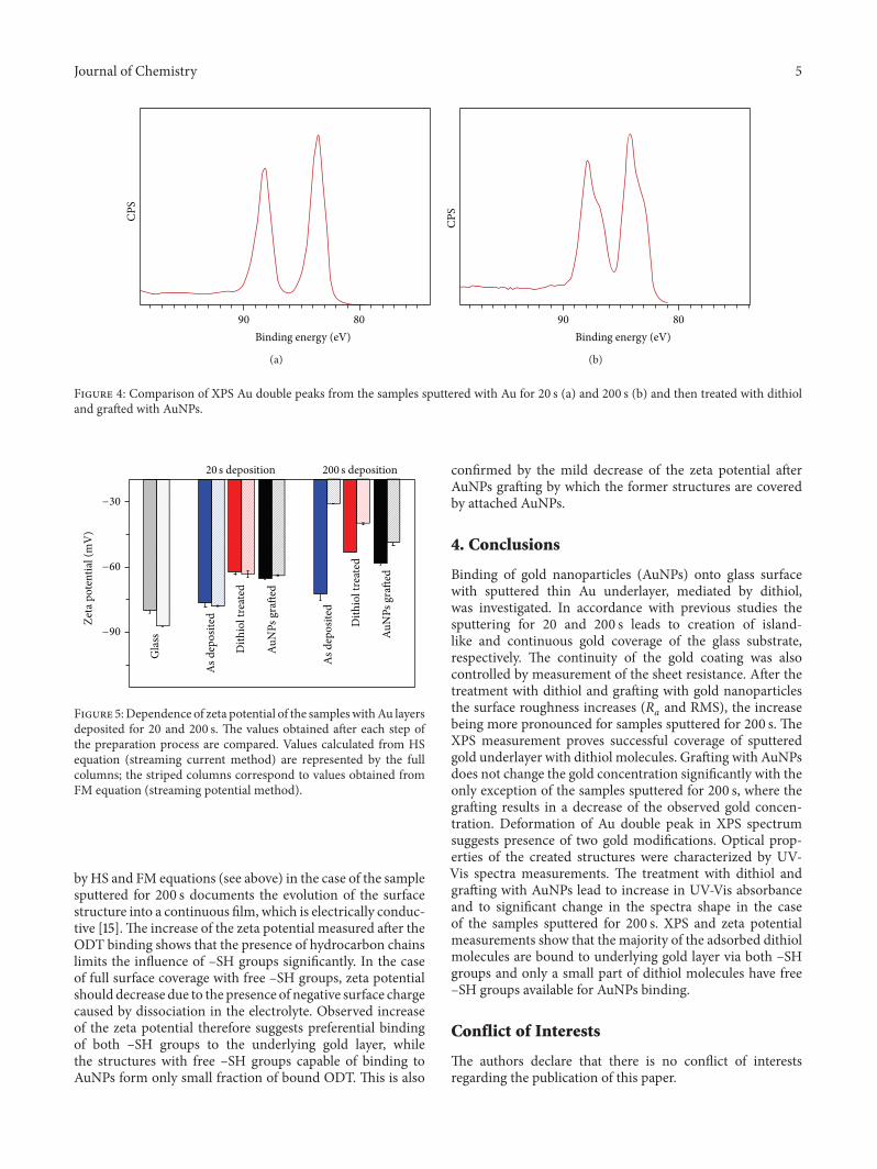
9Ω. Significant deformation of the XPS gold peaks,
observed on the sample sputtered for 200 s with Au andwith grafted AuNPs in comparison with sample with Audeposited for 20 s (see Figure 4), cannot be caused by samplecharging during the XPS measurement and rather indicatesthe presence of two forms of Au in the samples.
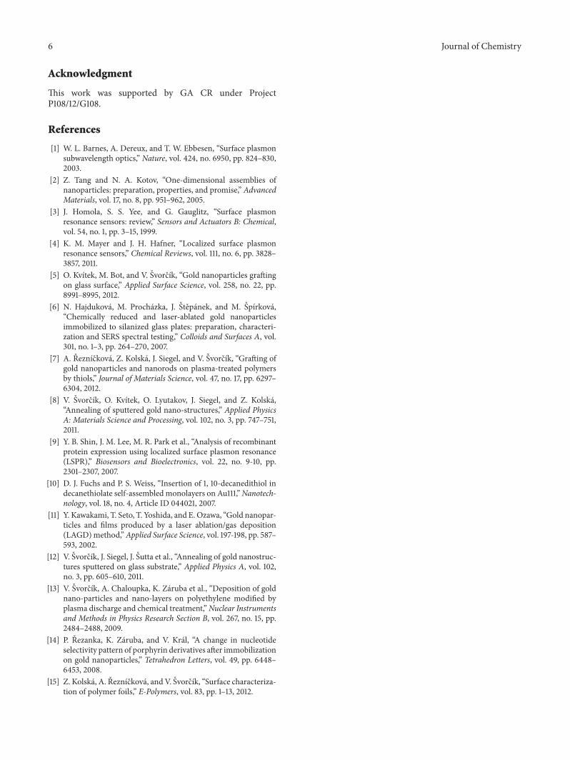
Results of zeta potential measurement are shown inFigure 5. Zeta potential of the samples increases after the Ausputtering.The big difference between the values determined
4 Journal of Chemistry
Ra = 0.6nmRMS = 0.9nm
Ra = 2.2nmRMS = 2.9nm
Ra = 6.2nmRMS = 8.2nm
Ra = 0.8nmRMS = 2.0nm
20 sdeposition
200 sdeposition
As deposited AuNPs grafted
1
11
1
00
1 1
1 100
00
00
11.5nm
0nm 0nm
0nm 0nm
35nm
21nm 51nm
(𝜇m)
(𝜇m)
(𝜇m) (𝜇m)
(𝜇m)
(𝜇m)
(𝜇m)
(𝜇m)
(a) (b)
Figure 2: AFM images of the samples Au sputtered for 20 and 200 s (a) and after dithiol treatment and AuNPs grafting (b).
0.08
0.12
0.16
0.20
0.24
0.28
0.32
Abso
rban
ce
400 500 600 700 800
Wavelength (nm)
AuNPs graftedDithiol treatedAs deposited
20 s
(a)
400 500 600 700 800
Wavelength (nm)
AuNPs graftedDithiol treatedAs deposited
0.7
0.8
0.9
1.0
1.1
1.2
1.3
200 s
Abso
rban
ce
(b)
Figure 3: UV-Vis spectra of the samples after each step of preparation (as sputtered with gold, after dithiol treatment and subsequent AuNPsgrafting). Samples were sputtered with Au for 20 s (a) and 200 s (b).
Journal of Chemistry 5
CPS
90 80
Binding energy (eV)
(a)
CPS
90 80
Binding energy (eV)
(b)
Figure 4: Comparison of XPS Au double peaks from the samples sputtered with Au for 20 s (a) and 200 s (b) and then treated with dithioland grafted with AuNPs.
200 s deposition20 s deposition
−30
−60
−90
Zeta
pot
entia
l (m
V)
Gla
ss
As d
epos
ited
As d
epos
ited
Dith
iol t
reat
ed
Dith
iol t
reat
ed
AuN
Ps g
rafte
d
AuN
Ps g
rafte
d
Figure 5:Dependence of zeta potential of the sampleswithAu layersdeposited for 20 and 200 s. The values obtained after each step ofthe preparation process are compared. Values calculated from HSequation (streaming current method) are represented by the fullcolumns; the striped columns correspond to values obtained fromFM equation (streaming potential method).
by HS and FM equations (see above) in the case of the samplesputtered for 200 s documents the evolution of the surfacestructure into a continuous film, which is electrically conduc-tive [15].The increase of the zeta potential measured after theODT binding shows that the presence of hydrocarbon chainslimits the influence of –SH groups significantly. In the caseof full surface coverage with free –SH groups, zeta potentialshould decrease due to the presence of negative surface chargecaused by dissociation in the electrolyte. Observed increaseof the zeta potential therefore suggests preferential bindingof both –SH groups to the underlying gold layer, whilethe structures with free –SH groups capable of binding toAuNPs form only small fraction of bound ODT. This is also
confirmed by the mild decrease of the zeta potential afterAuNPs grafting by which the former structures are coveredby attached AuNPs.
4. Conclusions
Binding of gold nanoparticles (AuNPs) onto glass surfacewith sputtered thin Au underlayer, mediated by dithiol,was investigated. In accordance with previous studies thesputtering for 20 and 200 s leads to creation of island-like and continuous gold coverage of the glass substrate,respectively. The continuity of the gold coating was alsocontrolled by measurement of the sheet resistance. After thetreatment with dithiol and grafting with gold nanoparticlesthe surface roughness increases (Ra and RMS), the increasebeing more pronounced for samples sputtered for 200 s. TheXPS measurement proves successful coverage of sputteredgold underlayer with dithiol molecules. Grafting with AuNPsdoes not change the gold concentration significantly with theonly exception of the samples sputtered for 200 s, where thegrafting results in a decrease of the observed gold concen-tration. Deformation of Au double peak in XPS spectrumsuggests presence of two gold modifications. Optical prop-erties of the created structures were characterized by UV-Vis spectra measurements. The treatment with dithiol andgrafting with AuNPs lead to increase in UV-Vis absorbanceand to significant change in the spectra shape in the caseof the samples sputtered for 200 s. XPS and zeta potentialmeasurements show that the majority of the adsorbed dithiolmolecules are bound to underlying gold layer via both –SHgroups and only a small part of dithiol molecules have free–SH groups available for AuNPs binding.
Conflict of Interests
The authors declare that there is no conflict of interestsregarding the publication of this paper.
6 Journal of Chemistry
Acknowledgment
This work was supported by GA CR under ProjectP108/12/G108.
References
[1] W. L. Barnes, A. Dereux, and T. W. Ebbesen, “Surface plasmonsubwavelength optics,” Nature, vol. 424, no. 6950, pp. 824–830,2003.
[2] Z. Tang and N. A. Kotov, “One-dimensional assemblies ofnanoparticles: preparation, properties, and promise,” AdvancedMaterials, vol. 17, no. 8, pp. 951–962, 2005.
[3] J. Homola, S. S. Yee, and G. Gauglitz, “Surface plasmonresonance sensors: review,” Sensors and Actuators B: Chemical,vol. 54, no. 1, pp. 3–15, 1999.
[4] K. M. Mayer and J. H. Hafner, “Localized surface plasmonresonance sensors,” Chemical Reviews, vol. 111, no. 6, pp. 3828–3857, 2011.
[5] O. Kvıtek, M. Bot, and V. Svorcık, “Gold nanoparticles graftingon glass surface,” Applied Surface Science, vol. 258, no. 22, pp.8991–8995, 2012.
[6] N. Hajdukova, M. Prochazka, J. Stepanek, and M. Spırkova,“Chemically reduced and laser-ablated gold nanoparticlesimmobilized to silanized glass plates: preparation, characteri-zation and SERS spectral testing,” Colloids and Surfaces A, vol.301, no. 1–3, pp. 264–270, 2007.
[7] A. Reznıckova, Z. Kolska, J. Siegel, and V. Svorcık, “Grafting ofgold nanoparticles and nanorods on plasma-treated polymersby thiols,” Journal of Materials Science, vol. 47, no. 17, pp. 6297–6304, 2012.
[8] V. Svorcık, O. Kvıtek, O. Lyutakov, J. Siegel, and Z. Kolska,“Annealing of sputtered gold nano-structures,” Applied PhysicsA: Materials Science and Processing, vol. 102, no. 3, pp. 747–751,2011.
[9] Y. B. Shin, J. M. Lee, M. R. Park et al., “Analysis of recombinantprotein expression using localized surface plasmon resonance(LSPR),” Biosensors and Bioelectronics, vol. 22, no. 9-10, pp.2301–2307, 2007.
[10] D. J. Fuchs and P. S. Weiss, “Insertion of 1, 10-decanedithiol indecanethiolate self-assembled monolayers on Au111,”Nanotech-nology, vol. 18, no. 4, Article ID 044021, 2007.
[11] Y. Kawakami, T. Seto, T. Yoshida, and E. Ozawa, “Gold nanopar-ticles and films produced by a laser ablation/gas deposition(LAGD)method,”Applied Surface Science, vol. 197-198, pp. 587–593, 2002.
[12] V. Svorcık, J. Siegel, J. Sutta et al., “Annealing of gold nanostruc-tures sputtered on glass substrate,” Applied Physics A, vol. 102,no. 3, pp. 605–610, 2011.
[13] V. Svorcık, A. Chaloupka, K. Zaruba et al., “Deposition of goldnano-particles and nano-layers on polyethylene modified byplasma discharge and chemical treatment,”Nuclear Instrumentsand Methods in Physics Research Section B, vol. 267, no. 15, pp.2484–2488, 2009.
[14] P. Rezanka, K. Zaruba, and V. Kral, “A change in nucleotideselectivity pattern of porphyrin derivatives after immobilizationon gold nanoparticles,” Tetrahedron Letters, vol. 49, pp. 6448–6453, 2008.
[15] Z. Kolska, A. Reznıckova, and V. Svorcık, “Surface characteriza-tion of polymer foils,” E-Polymers, vol. 83, pp. 1–13, 2012.

Submit your manuscripts athttp://www.hindawi.com
Hindawi Publishing Corporationhttp://www.hindawi.com Volume 2014
Inorganic ChemistryInternational Journal of
Hindawi Publishing Corporation http://www.hindawi.com Volume 2014
International Journal ofPhotoenergy
Hindawi Publishing Corporationhttp://www.hindawi.com Volume 2014
Carbohydrate Chemistry
International Journal of
Hindawi Publishing Corporationhttp://www.hindawi.com Volume 2014
Journal of
Chemistry
Hindawi Publishing Corporationhttp://www.hindawi.com Volume 2014
Advances in
Physical Chemistry
Hindawi Publishing Corporationhttp://www.hindawi.com
Analytical Methods in Chemistry
Journal of
Volume 2014
Bioinorganic Chemistry and ApplicationsHindawi Publishing Corporationhttp://www.hindawi.com Volume 2014
SpectroscopyInternational Journal of
Hindawi Publishing Corporationhttp://www.hindawi.com Volume 2014
The Scientific World JournalHindawi Publishing Corporation http://www.hindawi.com Volume 2014
Medicinal ChemistryInternational Journal of
Hindawi Publishing Corporationhttp://www.hindawi.com Volume 2014
Chromatography Research International
Hindawi Publishing Corporationhttp://www.hindawi.com Volume 2014
Applied ChemistryJournal of
Hindawi Publishing Corporationhttp://www.hindawi.com Volume 2014
Hindawi Publishing Corporationhttp://www.hindawi.com Volume 2014
Theoretical ChemistryJournal of
Hindawi Publishing Corporationhttp://www.hindawi.com Volume 2014
Journal of
Spectroscopy
Analytical ChemistryInternational Journal of
Hindawi Publishing Corporationhttp://www.hindawi.com Volume 2014
Journal of
Hindawi Publishing Corporationhttp://www.hindawi.com Volume 2014
Quantum Chemistry
Hindawi Publishing Corporationhttp://www.hindawi.com Volume 2014
Organic Chemistry International
ElectrochemistryInternational Journal of
Hindawi Publishing Corporation http://www.hindawi.com Volume 2014
Hindawi Publishing Corporationhttp://www.hindawi.com Volume 2014
CatalystsJournal of