Embed Size (px)
Citation preview
RESEARCH ARTICLE
Gaze-Informed Location Based Services
V. Anagnostopoulosa, M. Havlenab, P. Kiefera∗, I. Giannopoulosa, K. Schindlerc,M. Raubala
aInstitute of Cartography and Geoinformation, ETH Zurich; bComputer Vision Laboratory, ETH Zurich; cInstitute of Geodesy and Photogrammetry, ETH Zurich
Location-Based Services (LBS) provide more useful, intelligent assistance tousers by adapting to their geographic context. For some services that con-text goes beyond a location and includes further spatial parameters, such asthe user’s orientation or field of view. Here, we introduce Gaze-Informed LBS(GAIN-LBS), a novel type of LBS that takes into account the user’s viewingdirection. Such a system could, for instance, provide audio information aboutthe specific building a tourist is looking at from a vantage point. To determinethe viewing direction relative to the environment, we record the gaze directionrelative to the user’s head with a mobile eye tracker. Image data from thetracker’s forward-looking camera serve as input to determine the orientationof the head w.r.t. the surrounding scene, using computer vision methods thatallow one to estimate the relative transformation between the camera and aknown view of the scene in real-time and without the need for artificial markersor additional sensors. We focus on how to map the Point of Regard of a userto a reference system, for which the objects of interest are known in advance.In an experimental validation on three real city panoramas, we confirm thatthe approach can cope with head movements of varying speed, including fastrotations up to 63 deg/s. We further demonstrate the feasibility of GAIN-LBSfor tourist assistance with a proof-of-concept experiment in which a touristexplores a city panorama, where the approach achieved a recall that reachesover 99%. Finally, a GAIN-LBS can provide objective and qualitative ways ofexamining the gaze of a user based on what the user is currently looking at.
Keywords: Location Based Services; Eye Tracking; Point of Regard Estimation;Gaze-Based Interaction; Geographic Human-Computer Interaction
∗Corresponding author. Email: [email protected]
The Version of Record of this manuscript will be published and will be available in the "International Journal of Geographical Information Science" with DOI 10.1080/13658816.2017.1334896
http://dx.doi.org/10.1080/13658816.2017.1334896
2
1. Introduction
Over the last decades, Geographic Information Systems (GIS) have evolved from simplesystems that store and analyze geospatial data to complex systems that can identifyand satisfy their users’ needs. An example of such a system is the current generation ofLocation-Based Services (LBS). GIS and LBS are two terms that are closely related, sinceLBS can be regarded as a special kind of geographic information services that providegeospatial data to their users, based on their location (Jiang and Yao 2007).
LBS have transformed from simple services that take into account only the currentlocation of the user to highly personalized and adaptive services, based on many sensorreadings, location data analyses (e.g., Zook et al. 2015, Sia-Nowicka et al. 2016), detailedcontext models, and sophisticated inference of higher-level context. For instance, LBSmay infer the user’s needs from the trajectory (Kiefer et al. 2010, Huang and Gartner2014), or from her the user’s activities (Bao et al. 2012, Ying et al. 2011). Such inference ofhigher-level context often remains ambiguous: a particular spatio-temporal behavior, e.g.slowing down abruptly, may be caused by different user intentions that require differentadaptations of the service.
Visual search behavior arguably provides a more direct cue about a person’s perceptualand cognitive processes than the trajectory (c.f. the eye-mind hypothesis in Just andCarpenter 1976).
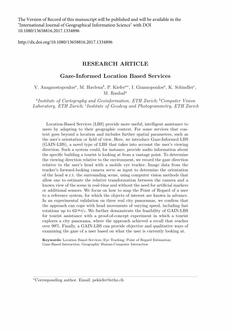
For instance, a wayfinder who is reading signs while slowing down abruptly is probablywondering which direction to take. Visual attention is measured with eye trackers (Justand Carpenter 1976), which can also be mounted to a person’s head and allow for freemovement in space (see Figure 1 top left). The gaze data can be accessed in real-time,which makes it possible to use gaze as an input modality for mobile geographic human-computer interaction (GeoHCI) (Giannopoulos et al. 2013).
Eye tracking is a common way to evaluate desktop (Coltekin et al. 2010) and mobileinterfaces (Paletta et al. 2014, Ludwig et al. 2014) for GeoHCI. As a mode of interactionits use has so far been largely limited to map interfaces on desktops (Duchowski andColtekin 2007, Kiefer and Giannopoulos 2012, Kiefer et al. 2013) or mobile devices (Gi-annopoulos et al. 2012). Attempts exist to interact with small objects in indoor spacesvia the user’s gaze (Toyama et al. 2012), but we are not aware of any work that exploitsgaze for spatial interaction in large-scale environments (e.g., cities).
Here, we propose to use gaze-based interaction in large outdoor environments for anovel type of LBS, which we call Gaze-Informed LBS (GAIN-LBS). While such servicesmay in principle use both, gaze on the assistance system and on objects in the envi-ronment, we focus on the latter. Our exemplary use case is that of a tourist viewing acity panorama from a vantage point (refer to Figure 1). A future gaze-informed touristguide could provide information on the building looked at, guide the user through thepanorama interactively, or provide recommendations that match the user’s interests. Asystem like that will be important not only for the LBS community but also in a largerGIScience context since it will allow to store and analyze the users’ visual attention inoutdoor environments.
The contributions of this article are:
• We introduce the concept of Gaze-Informed LBS (GAIN-LBS), a novel type of LBSthat takes into account the user’s Point of Regard (POR), based on the user’s gaze,and propose an architecture for this novel type of LBS.
• We propose a computer vision approach for mapping the gazes from a mobile eyetracking system to a georeferenced view, in order to detect the object of regard (OOR)

3
Figure 1. A user standing at a vantage point with an eye tracker (top left). The head-mountedeye tracker records the gaze in the field video (bottom left). The gaze is being mapped to areference image, with the blue point representing his current gaze and green points indicating hisgaze history. Potential touristic Areas of Interest are marked as yellow polygons (right).
in real-time.
• In an experimental validation, we compare several state-of-the-art algorithms for im-age feature extraction, using experimental data from three different vantage points,recorded with different velocities of head movement. The main focus of the study isto find suitable visual feature extractors from the computer vision literature, that willhelp us calculate the POR of a user and implement a GAIN-LBS (see sections 3 and4 for more details).
• We demonstrate the feasibility of GAIN-LBS for tourist assistance with a proof-of-concept experiment in which a tourist explores a city panorama.
We structure the paper as follows: Section 2 gives an overview of the relevant work,Section 3 introduces the GAIN-LBS architecture and describes how we solve the PORestimation and in Section 4 our system is evaluated. Finally, a discussion on the resultsis given (see Section 5) and the paper concludes with an outlook section (see Section 6).
2. Related work
2.1. From LBS to context-aware services
The original idea of LBS as services that adapt to location (Raubal 2011) has been ex-tended to a discussion on context-aware services. A number of papers has focused ondefinitions and taxonomies (Raubal and Panov 2009) for context, as well as on architec-tures for context-aware systems (see Poslad 2009 for an overview). In essence, context canbe classified into at least three types – user, environmental, and system context – and istypically seen as a multilevel concept, with sensor readings considered as more low-level(‘primary’) context, and other context inferred from these as higher-level (‘secondary’)context (Abowd et al. 1999).
The term ‘LBS’ is nowadays used in the literature for referring to services that uselocation as the main, but not the only type of context (Raper et al. 2007). One exampleof such service is a pedestrian wayfinding system that not only calculates the shortestpath but takes into considerations also other factors, such as the ease of using the system(Mackaness et al. 2014) or the users’ preferences (Huang et al. 2014) before calculating theoptimal route. Furthermore, current LBS architectures are being extended and new onesare being developed to include new technologies and to answer new research questions(see Tiwari et al. 2011 for a review of the LBS architectures and the recent trends inLBS community).
4
Our GAIN-LBS are based on two types of primary user context: user location and gazeposition (i.e., two types of spatial information). Extensions of GAIN-LBS will combinethese with other types of context (e.g., ‘temporal aspect of tourist exploration’, ‘contenton cultural objects’) and infer higher-level context from them (e.g., ‘touristic interest’).
For example, one challenge in the current research in LBS consists in how the temporalaspect of tourist exploration influences the tourist exploration behavior. Kremer andSchlieder 2014 have proposed four general design criteria for geo-recommendation servicesthat counterbalance the temporal restrictions. By including gaze as a primary context,a location based recommender can improve the visiting experience in touristic places,by taking into account not only the available time allocated for the visit, but also theinterest on specific objects the user has shown in previous locations.
Furthermore, a second challenge is how to access information on cultural objects andtheir content. Chianese et al. 2015 investigate the interactions with cultural objects andlocations, by adopting the Internet of Things (IoT) paradigm. They proposed a systemthat would simplify the access to the cultural objects and their content to the endusers. Our GAIN-LBS could further simplify the interactions between the visitors andcultural environments, since the user will only have to look at the object of interest foran interaction to begin.
Finally, a further challenge consists in creating a better user context for recommenda-tions (e.g., Aoidh et al. (2009)). Gaze can be a helpful mean for resolving this challenge,since it can provide an insight to the users interest. However, since none of the previouslysuggested LBS have taken the user’s gaze into account, it is yet unclear how the interac-tion with these touristic places can be improved by providing information on what theusers are currently looking at.
2.2. Eye tracking in GIScience and cartography
A person consciously or unconsciously focuses only on a fraction of the surroundingworld. This is done by shifting the visual attention through eye and head movementsfrom one place of the visual field to another. In other words, we move our eyes to bringa particular portion of the visible field of view into high resolution so that we may seein the fine detail whatever is at the central direction of gaze (Duchowski 2007).
However, there are situations when the gaze direction and the visual attention aredisassociated. As Duchowski (2007, p. 12) points out: “we assume that attention is linkedto gaze direction, but we acknowledge that it may not always be so”. This assumption (i.e.,that the gaze direction is linked to the visual attention) is called the eye-mind hypothesis(Just and Carpenter 1980, 1976). Thus, if we can track someone’s eye movements, wecan also follow the user’s attention (Duchowski 2007, Goldberg and Kotval 1999).
Eye tracking, a.k.a. gaze tracking or point of regard (POR) estimation, is the recordingof the orientation of the eyes in space (where a person is looking at) (Duchowski 2007).Based on the eye-mind hypothesis, it provides objective and quantitative evidence to-wards the examination of visual attention and a way to examine processes related tovisual search, visual perception, and cognition which occurs during the observation of astimulus or natural behavior (Richardson and Spivey 2004).
Although early work using eye tracking in cartography goes back to the 1970s (e.g.,Jenks 1973, Steinke 1987), there has been a strong rise in interest for investigating re-search questions related to GIScience and Cartography recently (refer to Kiefer et al. 2017for an overview). Eye tracking allows for the investigation of cognitive processes duringmap reading, and as a result design guidelines for maps or other spatial representations
5
can be derived (e.g., Fabrikant et al. 2010).The eye movements are recorded by devices known as eye trackers. In general, there
are two types of eye movements monitoring techniques. The first type measures the eyemovements remotely and is usually used in desktop computing. In this case, the eyetracker outputs the 2D coordinates of the user’s gaze on the screen. They are usuallyanalyzed by extracting information about the density of the users’ gazes in specific areas(Salvucci and Goldberg 2000). This step is required because visual perception only takesplace when the eye remains relatively still for a certain duration (which is then calleda fixation, where saccades denote the transition between fixations). The duration of afixation and the number of times a user is fixating at specific position is an indication ofthe visual attention of the user.
Ooms et al. (2012), for example, used remote eye tracking to measure the reaction timeof expert and novice map users while performing visual tasks to investigate the influenceof expertise on map viewing. Similarly, Coltekin et al. (2010) identified patterns of visualexploration and strategies during the use of highly interactive geographic interfaces.
While this technique works quite well on static stimuli, the evaluation of eye trackingdata collected on dynamic stimuli, such as animated maps, can be more challenging (e.g.,Andrienko et al. 2010).
The second technique for recording the eye movements is using head-mounted video-based (mobile) eye trackers. In contrast to the remote eye trackers, mobile eye trackershave a field-of-view (FOV) camera that records and outputs the scene and the user’sgaze as 2D coordinates. With a mobile eye tracker, the user is free to look and movearound in the environment. This allows for the analysis of the visual attention in mobilesituations, such as wayfinding or tourism.
For example, Kiefer et al. 2014a investigated the visual matching processes between theenvironment and a map during self-localization. Schwarzkopf et al. 2017 investigated theeye movements during collaborative wayfinding tasks. In a different approach, Ohm et al.2017 evaluated different designs for pedestrian navigation system. Finally, Kiefer et al.2014b investigated factors affecting the duration of visual exploration in city panoramas.
Using mobile eye trackers introduces new challenges, in particular the estimation ofthe Point of Regard (POR), as will be described in depth in Section 2.4.
2.3. Gazed-based interaction
One motivation for utilizing gaze as an input method for LBS is the possibility of derivinghigher-level information about a person’s cognitive processes from the visual attention(see also Section 2.2 – the eye-mind hypothesis in Just and Carpenter 1976). Froma human-computer interaction (HCI) point-of-view, this idea would relate to implicitinteraction, i.e., adapting the interface based on a user behavior that is not primarilyintended to trigger an interaction (Schmidt 2000). Explicit gaze-based interaction, onthe other hand, implies that the user is intentionally focusing on an interactive element(Majaranta et al. 2009), or performing a gaze gesture (Kangas et al. 2014a), with thegoal of triggering an interaction.
In principle, GAIN-LBS could use both, explicit and implicit interaction. In this paper,we introduce and evaluate the enabling technology for GAIN-LBS and do not focus onthe interaction paradigm per se. Our proof-of-concept evaluation (Section 4.3) thereforeassumes a simple explicit interaction paradigm.
Implicit gaze-based interaction with maps has been explored recently: while Kiefer andGiannopoulos (2012) describe how to match eye tracking data with the vector features
6
on a map, Kiefer et al. (2013) have applied machine learning to gaze data in order torecognize map activities, such as searching or route planning. Further approaches includegaze-contingent displays for level-of-detail management based on gaze (Duchowski andColtekin 2007), and the recording and display of gaze history to facilitate orientationon small-display maps (Giannopoulos et al. 2012). These ideas could be integrated intoa GAIN-LBS by considering both, gazes on buildings and gazes on a map shown on amobile device.
An explicit gaze-based interaction approach for wayfinding in outdoor scenarios hasalso been proposed, but was so far only evaluated in a virtual environment (Giannopouloset al. 2015). No running system for outdoor environments has been put forward yet.
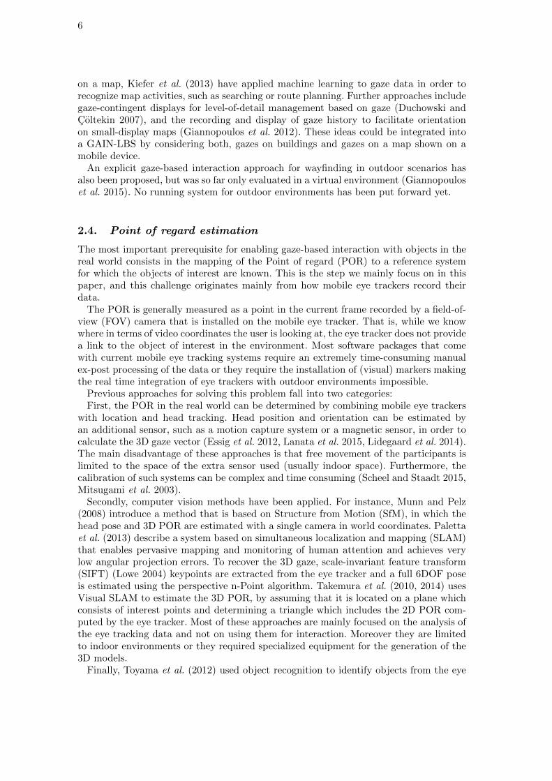
2.4. Point of regard estimation
The most important prerequisite for enabling gaze-based interaction with objects in thereal world consists in the mapping of the Point of regard (POR) to a reference systemfor which the objects of interest are known. This is the step we mainly focus on in thispaper, and this challenge originates mainly from how mobile eye trackers record theirdata.
The POR is generally measured as a point in the current frame recorded by a field-of-view (FOV) camera that is installed on the mobile eye tracker. That is, while we knowwhere in terms of video coordinates the user is looking at, the eye tracker does not providea link to the object of interest in the environment. Most software packages that comewith current mobile eye tracking systems require an extremely time-consuming manualex-post processing of the data or they require the installation of (visual) markers makingthe real time integration of eye trackers with outdoor environments impossible.
Previous approaches for solving this problem fall into two categories:First, the POR in the real world can be determined by combining mobile eye trackers
with location and head tracking. Head position and orientation can be estimated byan additional sensor, such as a motion capture system or a magnetic sensor, in order tocalculate the 3D gaze vector (Essig et al. 2012, Lanata et al. 2015, Lidegaard et al. 2014).The main disadvantage of these approaches is that free movement of the participants islimited to the space of the extra sensor used (usually indoor space). Furthermore, thecalibration of such systems can be complex and time consuming (Scheel and Staadt 2015,Mitsugami et al. 2003).
Secondly, computer vision methods have been applied. For instance, Munn and Pelz(2008) introduce a method that is based on Structure from Motion (SfM), in which thehead pose and 3D POR are estimated with a single camera in world coordinates. Palettaet al. (2013) describe a system based on simultaneous localization and mapping (SLAM)that enables pervasive mapping and monitoring of human attention and achieves verylow angular projection errors. To recover the 3D gaze, scale-invariant feature transform(SIFT) (Lowe 2004) keypoints are extracted from the eye tracker and a full 6DOF poseis estimated using the perspective n-Point algorithm. Takemura et al. (2010, 2014) usesVisual SLAM to estimate the 3D POR, by assuming that it is located on a plane whichconsists of interest points and determining a triangle which includes the 2D POR com-puted by the eye tracker. Most of these approaches are mainly focused on the analysis ofthe eye tracking data and not on using them for interaction. Moreover they are limitedto indoor environments or they required specialized equipment for the generation of the3D models.
Finally, Toyama et al. (2012) used object recognition to identify objects from the eye
7
tracking data, instead of mapping the gaze to the environment. The system worked inreal-time when image processing was reduced to less than 25 frames per second on asmall set of objects meaning that in more complex scenarios such as the ones in out-door environments, it might not be efficient. Similar approaches were investigated byHarmening and Pfeiffer (2013), as well as by (Brone et al. 2011).
3. Gaze-Informed LBS
In this section, we introduce the concept and architecture of Gaze-Informed LBS (GAIN-LBS), explain our method for Point of Regard (POR) estimation, and describe our im-plementation.
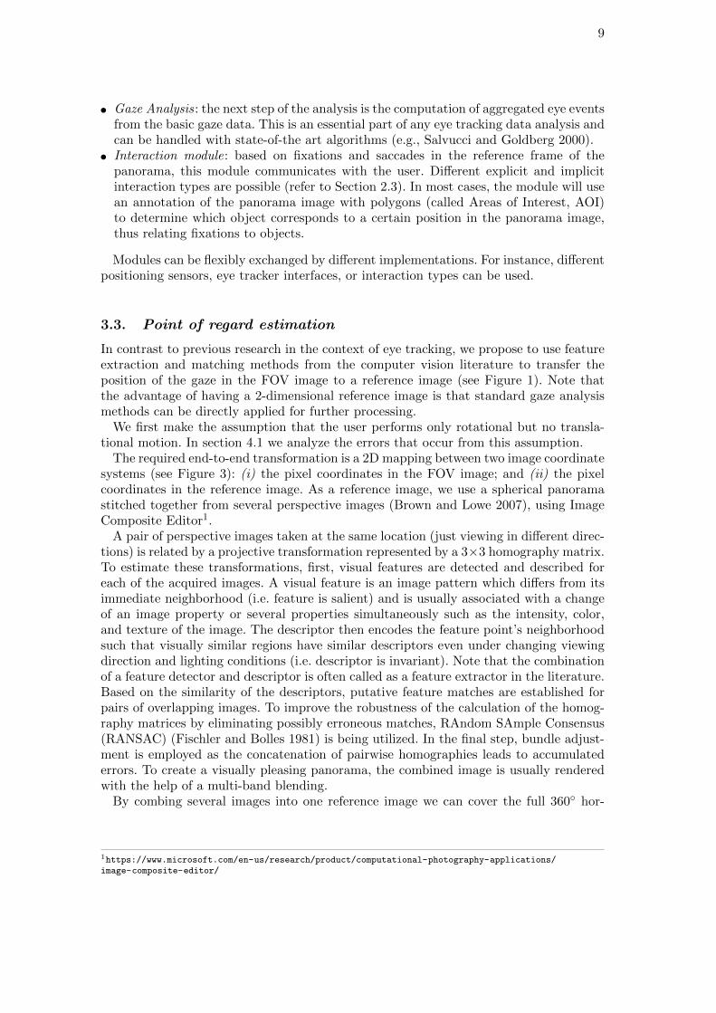
3.1. Motivating example and requirements
We illustrate the motivation for GAIN-LBS with a small tourist guide example:Bob is a tourist in “X-city”. He has taken the elevator up the famous “V-tower” from
where he has a beautiful view of the city. He takes out his phone and starts a classicLBS tourist guide. The app replays the audio information connected to his current lo-cation: “From here you have a beautiful view of the city center where the old town hallis located.” Bob does not find the building described by the application, so he pauses theaudio information and switches to a map service. He types in the name of the building,and the map marks his position and that of the old town hall. After several attentionswitches between the map on his device screen and the surrounding environment, he isfinally convinced of having identified the correct building and continues with the audioguide.
The scenario demonstrates the limitations of current LBS: the user needs to align thedescription provided by the guide with the real world. Visual search in the environment,as well as frequent attention switches between the environment and a visual display,become necessary. Further, the information provided by the audio guide is not temporallyaligned to what the user is looking at in that moment; the user’s preferred speed of visualexploration may be faster or slower than that assumed by the system. Imagine now thesame scenario with a GAIN-LBS:
Alice has just arrived at the same vantage point as Bob. Her GAIN-LBS informs herthat gaze-based touristic information is available for her current location. She mountsthe eye tracker and starts exploring the panorama. After a while her interest is attractedby one particular building. She is looking at the facade of that building when the servicestarts providing audio information: “It seems you are interested in medieval architecture,right? Let me give you some information on the building you are looking at. This is theold town hall which was constructed in the 15th century. It had been planned by the samemayor as the building you have looked at 20 seconds ago. . . . ”
The example provides an idea of how gaze-based interaction enhances the way LBScommunicate with their users: the system can adapt based on the current and previousfixations of the user, thus avoiding a mismatch of the information provided and theuser’s speed of visual exploration. No screen is required: the attention of the user remainson the panorama. Instructions of the service can unambiguously be matched with theenvironment and user interests can potentially be detected.
Implementing novel interactions such as those sketched in the example, requires asystem that is able to recognize efficiently and accurately which object in the panorama
8
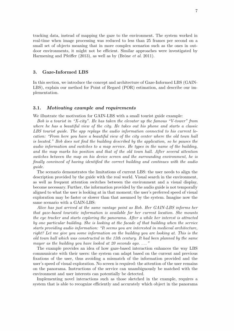
Figure 2. The system architecture of a Gaze-Informed LBS.
the user is looking at. Regarding efficiency, the system must be able to process the datafast enough to allow for real-time interaction. According to related work (Kangas et al.2014b), 200 milliseconds is the maximum delay between gaze on a trigger and feedbackby the system for which humans are still able to identify those two events with each other.We therefore use this as the maximum acceptable delay. In the eye tracking community,the accuracy is usually measured as the average angular distance from the actual gazepoint to the one measured by the eye tracker. The accuracy of the system must be highenough to allow distinguishing the buildings gazed at in the environment. Finally, anideal system should also be able to cope with varying light and/or weather conditions.
3.2. Architecture
Figure 2 illustrates our architecture for GAIN-LBS. It consists of the following modules:
• Positioning and geo-fencing : as with classic LBS, the user’s position is determined andintersected with a set of geo-fences. Once the user enters a geo-fence (a vantage pointin the tourist example), the GAIN-LBS is started. The GAIN-LBS is stopped whenthe user leaves the geo-fence.
• Eye tracking : this module receives the data from the mobile eye tracker and forwardsthem to the POR estimation module. It provides an interface to the eye tracker,making the rest of the system agnostic of the internal data structures of the concreteeye tracker model.
• POR estimation: here the correspondence of the gazes to a reference panorama imagetakes place. In Section 3.3 we describe our approach for this step.
9
• Gaze Analysis: the next step of the analysis is the computation of aggregated eye eventsfrom the basic gaze data. This is an essential part of any eye tracking data analysis andcan be handled with state-of-the art algorithms (e.g., Salvucci and Goldberg 2000).
• Interaction module: based on fixations and saccades in the reference frame of thepanorama, this module communicates with the user. Different explicit and implicitinteraction types are possible (refer to Section 2.3). In most cases, the module will usean annotation of the panorama image with polygons (called Areas of Interest, AOI)to determine which object corresponds to a certain position in the panorama image,thus relating fixations to objects.
Modules can be flexibly exchanged by different implementations. For instance, differentpositioning sensors, eye tracker interfaces, or interaction types can be used.
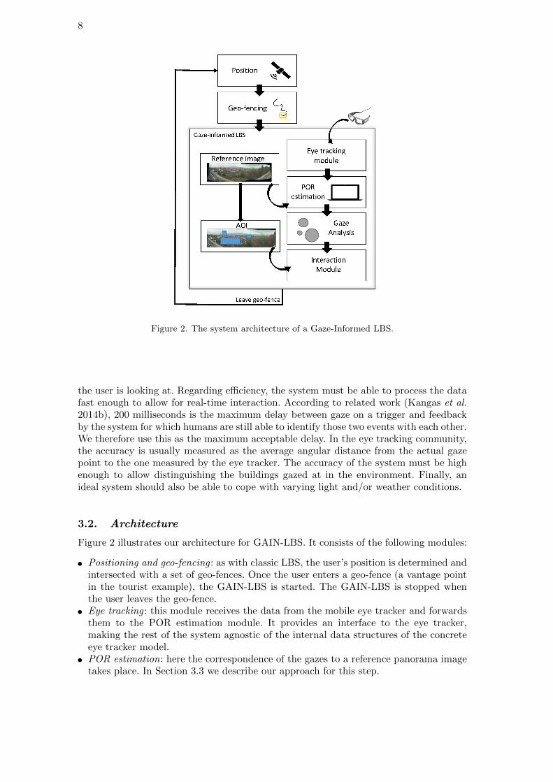
3.3. Point of regard estimation
In contrast to previous research in the context of eye tracking, we propose to use featureextraction and matching methods from the computer vision literature to transfer theposition of the gaze in the FOV image to a reference image (see Figure 1). Note thatthe advantage of having a 2-dimensional reference image is that standard gaze analysismethods can be directly applied for further processing.
We first make the assumption that the user performs only rotational but no transla-tional motion. In section 4.1 we analyze the errors that occur from this assumption.
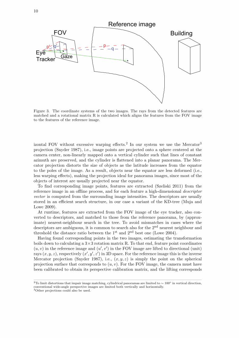
The required end-to-end transformation is a 2D mapping between two image coordinatesystems (see Figure 3): (i) the pixel coordinates in the FOV image; and (ii) the pixelcoordinates in the reference image. As a reference image, we use a spherical panoramastitched together from several perspective images (Brown and Lowe 2007), using ImageComposite Editor1.
A pair of perspective images taken at the same location (just viewing in different direc-tions) is related by a projective transformation represented by a 3×3 homography matrix.To estimate these transformations, first, visual features are detected and described foreach of the acquired images. A visual feature is an image pattern which differs from itsimmediate neighborhood (i.e. feature is salient) and is usually associated with a changeof an image property or several properties simultaneously such as the intensity, color,and texture of the image. The descriptor then encodes the feature point’s neighborhoodsuch that visually similar regions have similar descriptors even under changing viewingdirection and lighting conditions (i.e. descriptor is invariant). Note that the combinationof a feature detector and descriptor is often called as a feature extractor in the literature.Based on the similarity of the descriptors, putative feature matches are established forpairs of overlapping images. To improve the robustness of the calculation of the homog-raphy matrices by eliminating possibly erroneous matches, RAndom SAmple Consensus(RANSAC) (Fischler and Bolles 1981) is being utilized. In the final step, bundle adjust-ment is employed as the concatenation of pairwise homographies leads to accumulatederrors. To create a visually pleasing panorama, the combined image is usually renderedwith the help of a multi-band blending.
By combing several images into one reference image we can cover the full 360◦ hor-
1https://www.microsoft.com/en-us/research/product/computational-photography-applications/image-composite-editor/
10
Building
Reference image
FOV
Eye
TrackerGaze
p' q' pq
Figure 3. The coordinate systems of the two images. The rays from the detected features arematched and a rotational matrix R is calculated which aligns the features from the FOV imageto the features of the reference image.
izontal FOV without excessive warping effects.2 In our system we use the Mercator3
projection (Snyder 1987), i.e., image points are projected onto a sphere centered at thecamera center, non-linearly mapped onto a vertical cylinder such that lines of constantazimuth are preserved, and the cylinder is flattened into a planar panorama. The Mer-cator projection distorts the size of objects as the latitude increases from the equatorto the poles of the image. As a result, objects near the equator are less deformed (i.e.,less warping effects), making the projection ideal for panorama images, since most of theobjects of interest are usually projected near the equator.
To find corresponding image points, features are extracted (Szeliski 2011) from thereference image in an offline process, and for each feature a high-dimensional descriptorvector is computed from the surrounding image intensities. The descriptors are usuallystored in an efficient search structure, in our case a variant of the KD-tree (Muja andLowe 2009).
At runtime, features are extracted from the FOV image of the eye tracker, also con-verted to descriptors, and matched to those from the reference panorama, by (approx-imate) nearest-neighbour search in the tree. To avoid mismatches in cases where thedescriptors are ambiguous, it is common to search also for the 2nd nearest neighbour andthreshold the distance ratio between the 1st and 2nd best one (Lowe 2004).
Having found corresponding points in the two images, estimating the transformationboils down to calculating a 3×3 rotation matrix R. To that end, feature point coordinates(u, v) in the reference image and (u′, v′) in the FOV image are lifted to directional (unit)rays (x, y, z), respectively (x′, y′, z′) in 3D space. For the reference image this is the inverseMercator projection (Snyder 1987), i.e., (x, y, z) is simply the point on the sphericalprojection surface that corresponds to (u, v). For the FOV image, the camera must havebeen calibrated to obtain its perspective calibration matrix, and the lifting corresponds
2To limit distortions that impair image matching, cylindrical panoramas are limited to ∼ 100◦ in vertical direction,conventional wide-angle perspective images are limited both vertically and horizontally.3Other projections could also be used.
11
to applying the inverse calibration matrix to the image point in homogeneous coordinates(Hartley and Zisserman 2003).
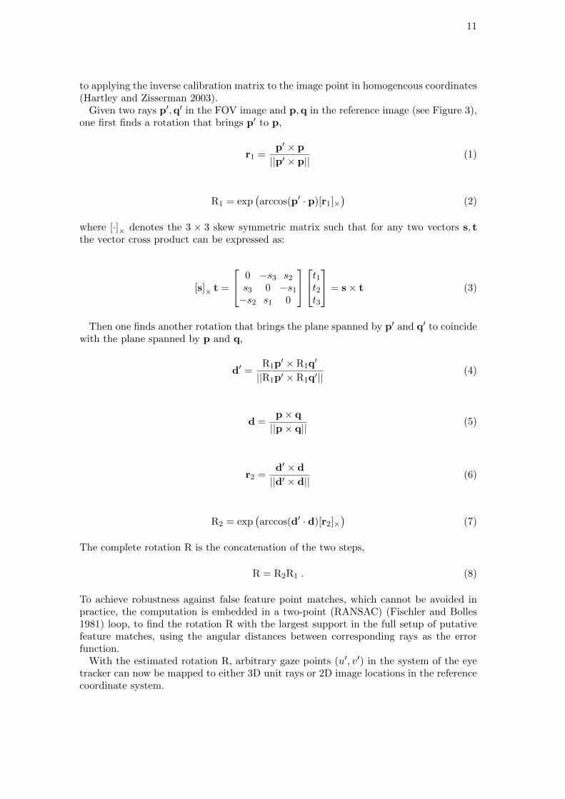
Given two rays p′,q′ in the FOV image and p,q in the reference image (see Figure 3),one first finds a rotation that brings p′ to p,
r1 =p′ × p
||p′ × p||(1)
R1 = exp(arccos(p′ · p)[r1]×
)(2)
where [·]× denotes the 3 × 3 skew symmetric matrix such that for any two vectors s, tthe vector cross product can be expressed as:
[s]× t =
0 −s3 s2
s3 0 −s1
−s2 s1 0
t1t2t3
= s× t (3)
Then one finds another rotation that brings the plane spanned by p′ and q′ to coincidewith the plane spanned by p and q,
d′ =R1p
′ × R1q′
||R1p′ × R1q′||(4)
d =p× q
||p× q||(5)
r2 =d′ × d
||d′ × d||(6)
R2 = exp(arccos(d′ · d)[r2]×
)(7)
The complete rotation R is the concatenation of the two steps,
R = R2R1 . (8)
To achieve robustness against false feature point matches, which cannot be avoided inpractice, the computation is embedded in a two-point (RANSAC) (Fischler and Bolles1981) loop, to find the rotation R with the largest support in the full setup of putativefeature matches, using the angular distances between corresponding rays as the errorfunction.
With the estimated rotation R, arbitrary gaze points (u′, v′) in the system of the eyetracker can now be mapped to either 3D unit rays or 2D image locations in the referencecoordinate system.
12
3.4. Implementation
For the implementation of the system, the SMI Eye Tracking Glasses v.1.81 with afrequency of 30Hz were employed. The software modules provided by the SMI Eye Tracker(i.e., iViewETG) were used for calibration, as well as the recording of the raw gaze data.The SMI API (i.e., iViewNG SDK) was utilized to access the gaze data from the eyetracker in real-time, returning the FOV image and the gaze data in the coordinate systemof this FOV image.
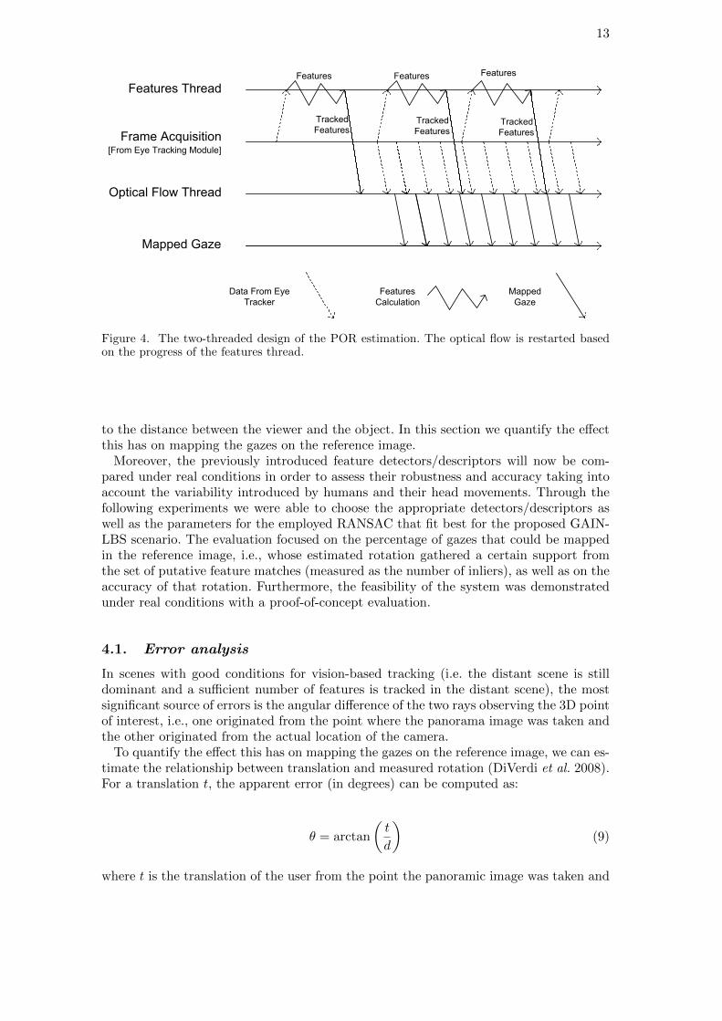
The image frames from the eye tracker were processed using the OpenCV library1 andthe given default values were used for the feature detectors/descriptors. As extractingfeatures requires a considerable amount of time and it is therefore not possible to extractfeatures from all frames of the 30Hz video stream, a two-threaded approach (see Figure 4)was chosen to achieve real-time performance. One thread (Features thread) was used toextract the features from a subset of frames of the eye tracker and match them to thereference image as described in Section 3.3. The second thread (Optical Flow thread)was used to track these features from one FOV frame to the next one by iterativelycomputing fast optical flow (Lucas and Kanade 1981) using image pyramids, withoutextracting new features in these frames.
For every incoming frame the rotation matrix ∆R w.r.t. the previous frame is calcu-lated using the tracked locations of the features as computed by the Optical Flow thread(similarly to Section 3.3). By knowing the rotation matrices between consecutive framesand between the original frame (i.e., the frame in which the features were extracted andthe reference image, we can compute a composed rotation matrix that maps the gazefrom the current frame to the reference image.
During the computation of the Optical Flow thread, drifts in the locations of the trackedfeatures might occur. This drifting error continues to grow until the Features thread hasfinished with the extraction of new features, allowing to restart the optical flow again,thus, accounting for this error. Furthermore, restarting the optical flow also allows us toaccount for the problem that occurs when the features tracked by the optical flow arelost due to excessive head rotation.
The current implementation allows the use of arbitrary feature detectors and descrip-tors. During our testing, we used feature detectors and descriptors that are knownto be robust and fast according to the computer vision literature (Heinly et al. 2012,Tuytelaars and Mikolajczyk 2008, Miksik and Mikolajczyk 2012). These are (see Sec-tion 4): ORB (Rublee et al. 2011), SURF (Bay et al. 2008), SIFT (Lowe 2004), Cen-SurE (Agrawal et al. 2008)–SURF (Bay et al. 2008), BRISK (Leutenegger et al. 2011),FAST (Rosten and Drummond 2006)–FREAK (Alahi et al. 2012), FAST (Rosten andDrummond 2006)–BRISK (Leutenegger et al. 2011), and CenSurE (Agrawal et al. 2008)–BRIEF (Calonder et al. 2010) (see also Krig 2016, Chapter 6 for a comprehensive tax-onomy of feature detectors/descriptors).
4. Evaluation
In the previous section we made the assumption that the user performs only rotationmotions. The approximation is justified in many outdoor scenarios, including sightseeingfrom panoramic lookouts, because the translational motion is typically small compared
1http://www.eyetracking-glasses.com1http://opencv.org
13
Frame Acquisition[From Eye Tracking Module]
Features Thread
Optical Flow Thread
Mapped Gaze
Features Features
Data From Eye
Tracker
Features
Calculation
Mapped
Gaze
Tracked
FeaturesTracked
FeaturesTracked
Features
Features
Figure 4. The two-threaded design of the POR estimation. The optical flow is restarted basedon the progress of the features thread.
to the distance between the viewer and the object. In this section we quantify the effectthis has on mapping the gazes on the reference image.
Moreover, the previously introduced feature detectors/descriptors will now be com-pared under real conditions in order to assess their robustness and accuracy taking intoaccount the variability introduced by humans and their head movements. Through thefollowing experiments we were able to choose the appropriate detectors/descriptors aswell as the parameters for the employed RANSAC that fit best for the proposed GAIN-LBS scenario. The evaluation focused on the percentage of gazes that could be mappedin the reference image, i.e., whose estimated rotation gathered a certain support fromthe set of putative feature matches (measured as the number of inliers), as well as on theaccuracy of that rotation. Furthermore, the feasibility of the system was demonstratedunder real conditions with a proof-of-concept evaluation.
4.1. Error analysis
In scenes with good conditions for vision-based tracking (i.e. the distant scene is stilldominant and a sufficient number of features is tracked in the distant scene), the mostsignificant source of errors is the angular difference of the two rays observing the 3D pointof interest, i.e., one originated from the point where the panorama image was taken andthe other originated from the actual location of the camera.
To quantify the effect this has on mapping the gazes on the reference image, we can es-timate the relationship between translation and measured rotation (DiVerdi et al. 2008).For a translation t, the apparent error (in degrees) can be computed as:
θ = arctan
(t
d
)(9)
where t is the translation of the user from the point the panoramic image was taken and
14
�
�
�
�
�
�
��� ���� �����
���������� �������������������������������
���������������� ��������
�
�
��
��
���� �������� ����
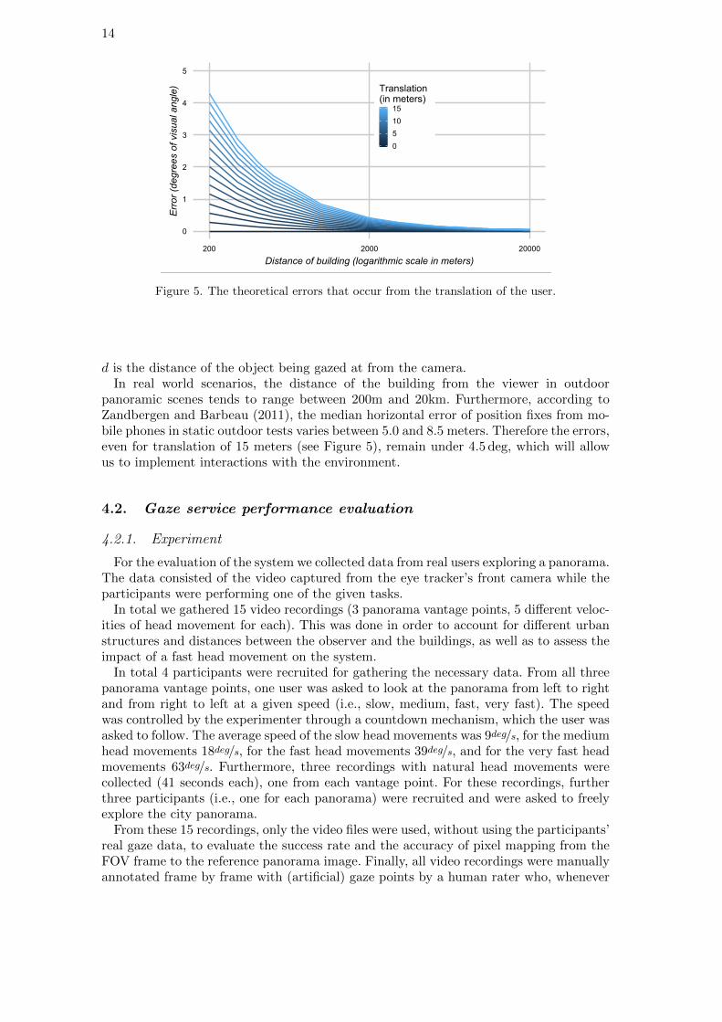
Figure 5. The theoretical errors that occur from the translation of the user.
d is the distance of the object being gazed at from the camera.In real world scenarios, the distance of the building from the viewer in outdoor
panoramic scenes tends to range between 200m and 20km. Furthermore, according toZandbergen and Barbeau (2011), the median horizontal error of position fixes from mo-bile phones in static outdoor tests varies between 5.0 and 8.5 meters. Therefore the errors,even for translation of 15 meters (see Figure 5), remain under 4.5 deg, which will allowus to implement interactions with the environment.
4.2. Gaze service performance evaluation
4.2.1. Experiment
For the evaluation of the system we collected data from real users exploring a panorama.The data consisted of the video captured from the eye tracker’s front camera while theparticipants were performing one of the given tasks.
In total we gathered 15 video recordings (3 panorama vantage points, 5 different veloc-ities of head movement for each). This was done in order to account for different urbanstructures and distances between the observer and the buildings, as well as to assess theimpact of a fast head movement on the system.
In total 4 participants were recruited for gathering the necessary data. From all threepanorama vantage points, one user was asked to look at the panorama from left to rightand from right to left at a given speed (i.e., slow, medium, fast, very fast). The speedwas controlled by the experimenter through a countdown mechanism, which the user wasasked to follow. The average speed of the slow head movements was 9deg/s, for the mediumhead movements 18deg/s, for the fast head movements 39deg/s, and for the very fast headmovements 63deg/s. Furthermore, three recordings with natural head movements werecollected (41 seconds each), one from each vantage point. For these recordings, furtherthree participants (i.e., one for each panorama) were recruited and were asked to freelyexplore the city panorama.
From these 15 recordings, only the video files were used, without using the participants’real gaze data, to evaluate the success rate and the accuracy of pixel mapping from theFOV frame to the reference panorama image. Finally, all video recordings were manuallyannotated frame by frame with (artificial) gaze points by a human rater who, whenever
15
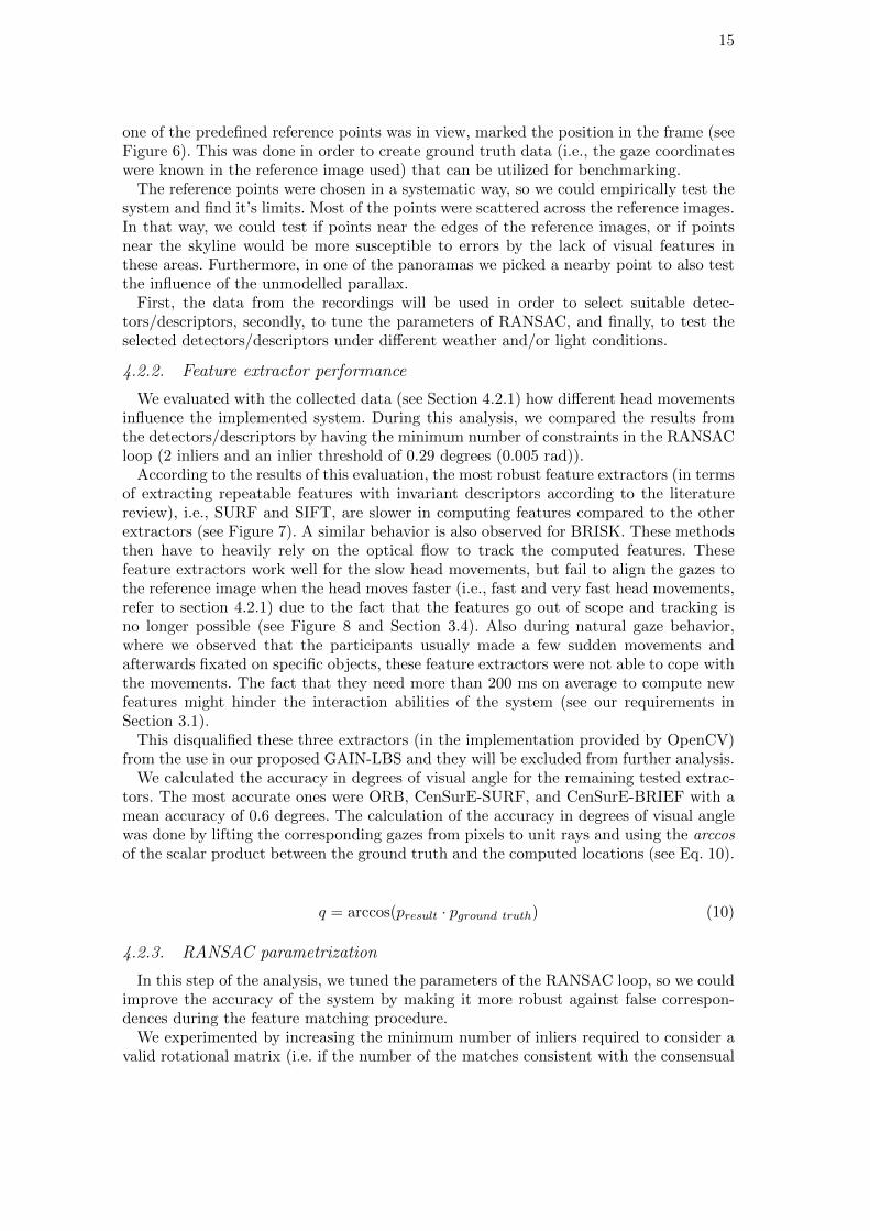
one of the predefined reference points was in view, marked the position in the frame (seeFigure 6). This was done in order to create ground truth data (i.e., the gaze coordinateswere known in the reference image used) that can be utilized for benchmarking.
The reference points were chosen in a systematic way, so we could empirically test thesystem and find it’s limits. Most of the points were scattered across the reference images.In that way, we could test if points near the edges of the reference images, or if pointsnear the skyline would be more susceptible to errors by the lack of visual features inthese areas. Furthermore, in one of the panoramas we picked a nearby point to also testthe influence of the unmodelled parallax.
First, the data from the recordings will be used in order to select suitable detec-tors/descriptors, secondly, to tune the parameters of RANSAC, and finally, to test theselected detectors/descriptors under different weather and/or light conditions.
4.2.2. Feature extractor performance
We evaluated with the collected data (see Section 4.2.1) how different head movementsinfluence the implemented system. During this analysis, we compared the results fromthe detectors/descriptors by having the minimum number of constraints in the RANSACloop (2 inliers and an inlier threshold of 0.29 degrees (0.005 rad)).
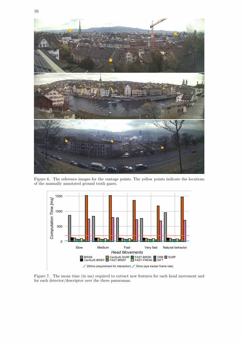
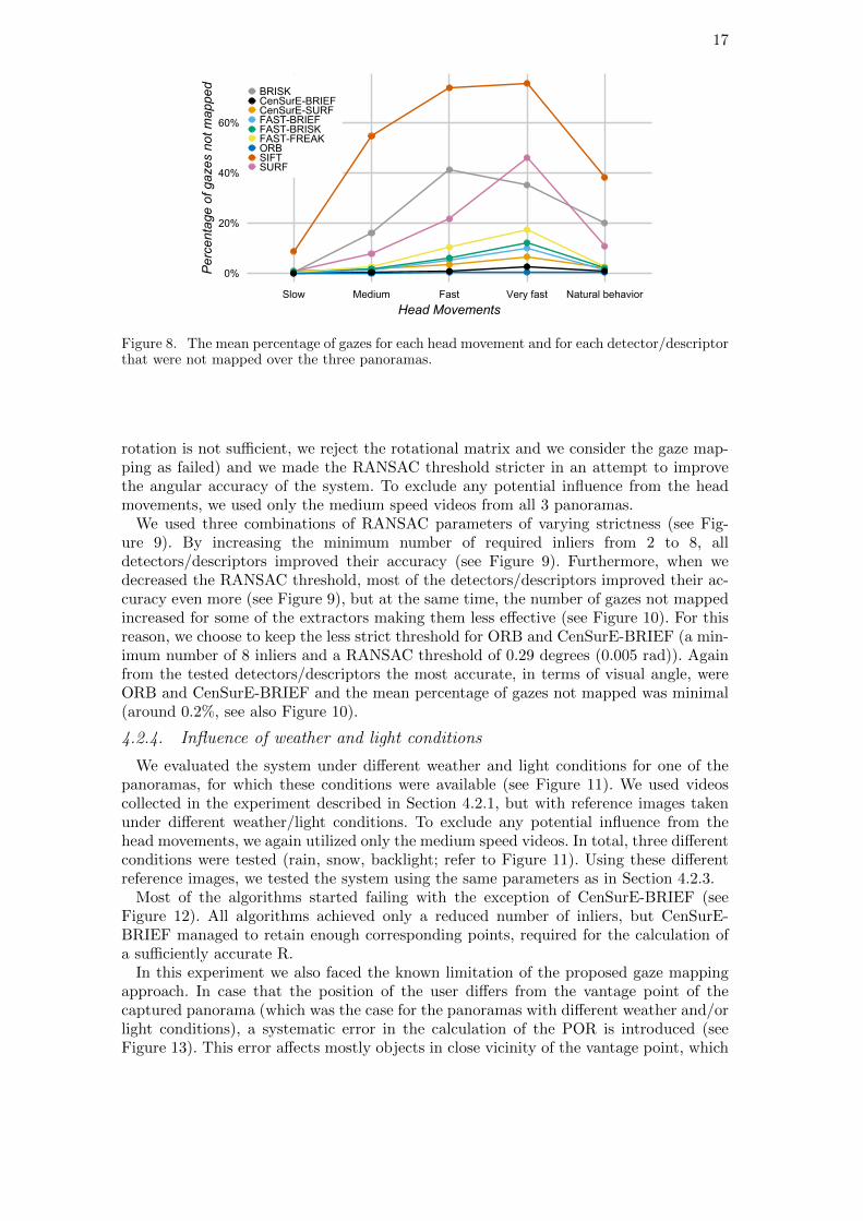
According to the results of this evaluation, the most robust feature extractors (in termsof extracting repeatable features with invariant descriptors according to the literaturereview), i.e., SURF and SIFT, are slower in computing features compared to the otherextractors (see Figure 7). A similar behavior is also observed for BRISK. These methodsthen have to heavily rely on the optical flow to track the computed features. Thesefeature extractors work well for the slow head movements, but fail to align the gazes tothe reference image when the head moves faster (i.e., fast and very fast head movements,refer to section 4.2.1) due to the fact that the features go out of scope and tracking isno longer possible (see Figure 8 and Section 3.4). Also during natural gaze behavior,where we observed that the participants usually made a few sudden movements andafterwards fixated on specific objects, these feature extractors were not able to cope withthe movements. The fact that they need more than 200 ms on average to compute newfeatures might hinder the interaction abilities of the system (see our requirements inSection 3.1).
This disqualified these three extractors (in the implementation provided by OpenCV)from the use in our proposed GAIN-LBS and they will be excluded from further analysis.
We calculated the accuracy in degrees of visual angle for the remaining tested extrac-tors. The most accurate ones were ORB, CenSurE-SURF, and CenSurE-BRIEF with amean accuracy of 0.6 degrees. The calculation of the accuracy in degrees of visual anglewas done by lifting the corresponding gazes from pixels to unit rays and using the arccosof the scalar product between the ground truth and the computed locations (see Eq. 10).
q = arccos(presult · pground truth) (10)
4.2.3. RANSAC parametrization
In this step of the analysis, we tuned the parameters of the RANSAC loop, so we couldimprove the accuracy of the system by making it more robust against false correspon-dences during the feature matching procedure.
We experimented by increasing the minimum number of inliers required to consider avalid rotational matrix (i.e. if the number of the matches consistent with the consensual
16
Figure 6. The reference images for the vantage points. The yellow points indicate the locationsof the manually annotated ground truth gazes.
�
���
����
����
���� ��� ���� �������� ���������������
������������
����������������
������ ���!"���!�
� ���!"�#���$�%"���!�
�$�%"������$�%"��!$�
&�����%
�#��
'�� ��(�)��� ������� ���*��� + ,, ��(�����*-����� ����+
Figure 7. The mean time (in ms) required to extract new features for each head movement andfor each detector/descriptor over the three panoramas.
17
��
���
���
���
��� �� �� ���� ��������� ������������� ��
������������
��������������������������
���� !�"���#$���#�!�"���#$�%���&�'$���#��&�'$���� �&�'$��#& (�����'�%��
Figure 8. The mean percentage of gazes for each head movement and for each detector/descriptorthat were not mapped over the three panoramas.
rotation is not sufficient, we reject the rotational matrix and we consider the gaze map-ping as failed) and we made the RANSAC threshold stricter in an attempt to improvethe angular accuracy of the system. To exclude any potential influence from the headmovements, we used only the medium speed videos from all 3 panoramas.
We used three combinations of RANSAC parameters of varying strictness (see Fig-ure 9). By increasing the minimum number of required inliers from 2 to 8, alldetectors/descriptors improved their accuracy (see Figure 9). Furthermore, when wedecreased the RANSAC threshold, most of the detectors/descriptors improved their ac-curacy even more (see Figure 9), but at the same time, the number of gazes not mappedincreased for some of the extractors making them less effective (see Figure 10). For thisreason, we choose to keep the less strict threshold for ORB and CenSurE-BRIEF (a min-imum number of 8 inliers and a RANSAC threshold of 0.29 degrees (0.005 rad)). Againfrom the tested detectors/descriptors the most accurate, in terms of visual angle, wereORB and CenSurE-BRIEF and the mean percentage of gazes not mapped was minimal(around 0.2%, see also Figure 10).
4.2.4. Influence of weather and light conditions
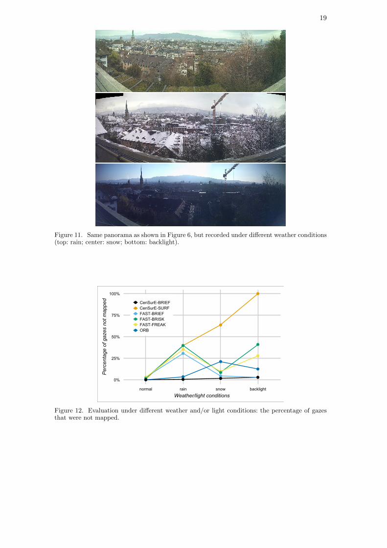
We evaluated the system under different weather and light conditions for one of thepanoramas, for which these conditions were available (see Figure 11). We used videoscollected in the experiment described in Section 4.2.1, but with reference images takenunder different weather/light conditions. To exclude any potential influence from thehead movements, we again utilized only the medium speed videos. In total, three differentconditions were tested (rain, snow, backlight; refer to Figure 11). Using these differentreference images, we tested the system using the same parameters as in Section 4.2.3.
Most of the algorithms started failing with the exception of CenSurE-BRIEF (seeFigure 12). All algorithms achieved only a reduced number of inliers, but CenSurE-BRIEF managed to retain enough corresponding points, required for the calculation ofa sufficiently accurate R.
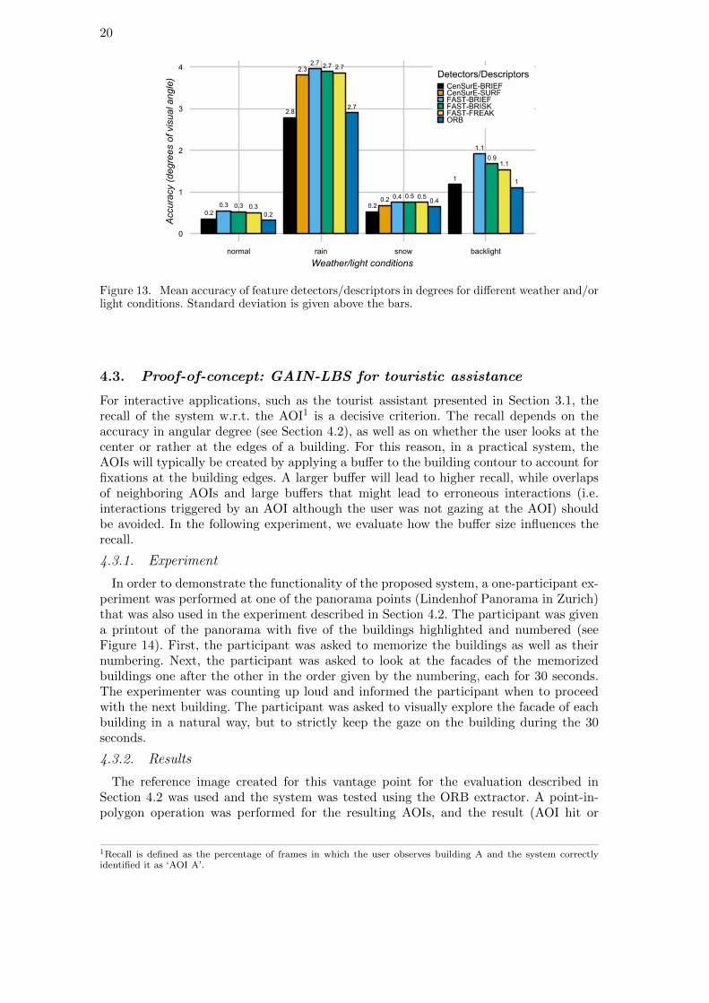
In this experiment we also faced the known limitation of the proposed gaze mappingapproach. In case that the position of the user differs from the vantage point of thecaptured panorama (which was the case for the panoramas with different weather and/orlight conditions), a systematic error in the calculation of the POR is introduced (seeFigure 13). This error affects mostly objects in close vicinity of the vantage point, which
18
���
����
���
����
���
��� ���
����
���
���
��� ���
��
���
������
���
�
�
�
�
�� ���� �� ���� �� �����
�������������
�������������� ������ ����������
������������������������������ !�"���������# ""$�%�� !�""$�%�� !�&"$�%�" �$&' �
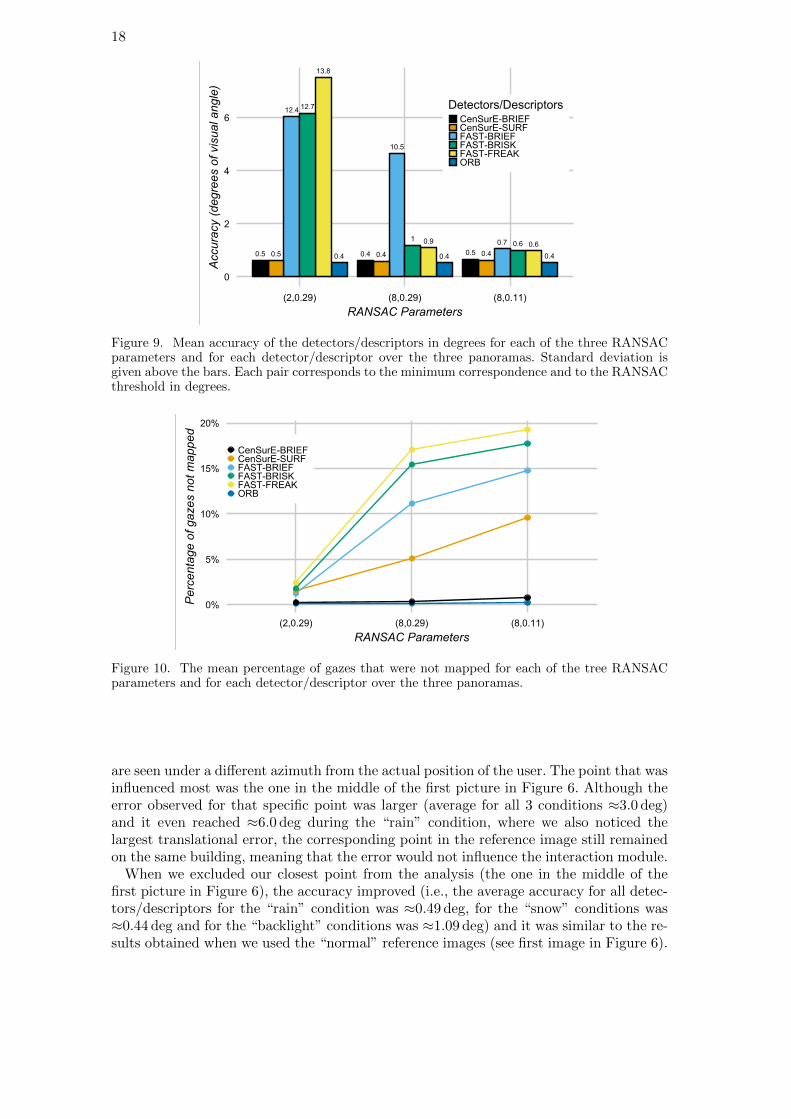
Figure 9. Mean accuracy of the detectors/descriptors in degrees for each of the three RANSACparameters and for each detector/descriptor over the three panoramas. Standard deviation isgiven above the bars. Each pair corresponds to the minimum correspondence and to the RANSACthreshold in degrees.
��
��
���
���
���
������ ������ �������
�������������
����������������� ����������
� ������������ �������������������������������������������
Figure 10. The mean percentage of gazes that were not mapped for each of the tree RANSACparameters and for each detector/descriptor over the three panoramas.
are seen under a different azimuth from the actual position of the user. The point that wasinfluenced most was the one in the middle of the first picture in Figure 6. Although theerror observed for that specific point was larger (average for all 3 conditions ≈3.0 deg)and it even reached ≈6.0 deg during the “rain” condition, where we also noticed thelargest translational error, the corresponding point in the reference image still remainedon the same building, meaning that the error would not influence the interaction module.
When we excluded our closest point from the analysis (the one in the middle of thefirst picture in Figure 6), the accuracy improved (i.e., the average accuracy for all detec-tors/descriptors for the “rain” condition was ≈0.49 deg, for the “snow” conditions was≈0.44 deg and for the “backlight” conditions was ≈1.09 deg) and it was similar to the re-sults obtained when we used the “normal” reference images (see first image in Figure 6).
19
Figure 11. Same panorama as shown in Figure 6, but recorded under different weather conditions(top: rain; center: snow; bottom: backlight).
��
���
���
���
����
���� � � ���� ����� ���
������������� ��� ��
���������� �������� ��������
������������
�������� ��
�!�"������
�!�"�����#
�!�"����!#
$��
Figure 12. Evaluation under different weather and/or light conditions: the percentage of gazesthat were not mapped.
20
���
��� ���������
���
������ ������
���
��������� ������
���
�
���
�
�
�
�
�� ��� ��� ���� ���������
������������� ��� ��
����������������� ������������� ������� ������ ���� �
���� !"#$%!&���� !"�'$&&(�)"#$%!&&(�)"#$%�*&(�)"&$!(*+$#
Figure 13. Mean accuracy of feature detectors/descriptors in degrees for different weather and/orlight conditions. Standard deviation is given above the bars.
4.3. Proof-of-concept: GAIN-LBS for touristic assistance
For interactive applications, such as the tourist assistant presented in Section 3.1, therecall of the system w.r.t. the AOI1 is a decisive criterion. The recall depends on theaccuracy in angular degree (see Section 4.2), as well as on whether the user looks at thecenter or rather at the edges of a building. For this reason, in a practical system, theAOIs will typically be created by applying a buffer to the building contour to account forfixations at the building edges. A larger buffer will lead to higher recall, while overlapsof neighboring AOIs and large buffers that might lead to erroneous interactions (i.e.interactions triggered by an AOI although the user was not gazing at the AOI) shouldbe avoided. In the following experiment, we evaluate how the buffer size influences therecall.
4.3.1. Experiment
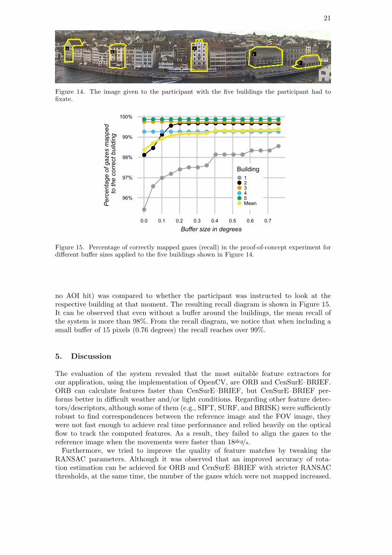
In order to demonstrate the functionality of the proposed system, a one-participant ex-periment was performed at one of the panorama points (Lindenhof Panorama in Zurich)that was also used in the experiment described in Section 4.2. The participant was givena printout of the panorama with five of the buildings highlighted and numbered (seeFigure 14). First, the participant was asked to memorize the buildings as well as theirnumbering. Next, the participant was asked to look at the facades of the memorizedbuildings one after the other in the order given by the numbering, each for 30 seconds.The experimenter was counting up loud and informed the participant when to proceedwith the next building. The participant was asked to visually explore the facade of eachbuilding in a natural way, but to strictly keep the gaze on the building during the 30seconds.
4.3.2. Results
The reference image created for this vantage point for the evaluation described inSection 4.2 was used and the system was tested using the ORB extractor. A point-in-polygon operation was performed for the resulting AOIs, and the result (AOI hit or
1Recall is defined as the percentage of frames in which the user observes building A and the system correctlyidentified it as ‘AOI A’.
21
Figure 14. The image given to the participant with the five buildings the participant had tofixate.
���
���
���
���
����
��� ��� �� �� ��� ��� ��� ���
��������������������
������������������������
�����������������������
�������
�������
Figure 15. Percentage of correctly mapped gazes (recall) in the proof-of-concept experiment fordifferent buffer sizes applied to the five buildings shown in Figure 14.
no AOI hit) was compared to whether the participant was instructed to look at therespective building at that moment. The resulting recall diagram is shown in Figure 15.It can be observed that even without a buffer around the buildings, the mean recall ofthe system is more than 98%. From the recall diagram, we notice that when including asmall buffer of 15 pixels (0.76 degrees) the recall reaches over 99%.
5. Discussion
The evaluation of the system revealed that the most suitable feature extractors forour application, using the implementation of OpenCV, are ORB and CenSurE–BRIEF.ORB can calculate features faster than CenSurE–BRIEF, but CenSurE–BRIEF per-forms better in difficult weather and/or light conditions. Regarding other feature detec-tors/descriptors, although some of them (e.g., SIFT, SURF, and BRISK) were sufficientlyrobust to find correspondences between the reference image and the FOV image, theywere not fast enough to achieve real time performance and relied heavily on the opticalflow to track the computed features. As a result, they failed to align the gazes to thereference image when the movements were faster than 18deg/s.
Furthermore, we tried to improve the quality of feature matches by tweaking theRANSAC parameters. Although it was observed that an improved accuracy of rota-tion estimation can be achieved for ORB and CenSurE–BRIEF with stricter RANSACthresholds, at the same time, the number of the gazes which were not mapped increased.
22
For this reason, it was chosen to keep the less strict thresholds for the RANSAC param-eters for these extractors. The robustness of different feature extractors was then testedunder various weather and light conditions. The number of matches which were consistentwith the consensual rotation decreased for all the tested extractors, but CenSurE–BRIEFmanaged to retain more than the minimum required number of corresponding points forthe calculation of the mapped gaze. Finally, although CenSurE-BRIEF is the most ro-bust of the detectors/descriptors that were tested, the mean accuracy of the estimatedrotation is worse than that of ORB and it is also almost two times slower than ORB (seeFigure 7) in calculating new features. We therefore recommend to use ORB as long asthe weather and light conditions allow for it, i.e., the number of putative feature matches(measured as the number of inliers) are sufficient.
A central objective of the presented experiments was to examine the suitability of theproposed platform for interactive applications. For that reason, a final experiment wasconducted that examined the recall of the system, i.e., how often the building the userwas gazing at was also correctly identified by the system. Adding a small buffer of 15pixels around building edges, the recall reached over 99%.
The novel system we proposed will remove the restriction of working only with usertrajectories in an LBS. It will provide an objective and qualitative way of examining thegaze of a user while overlooking a city panorama and it can form the basis for a systemgiving recommendations based on what the user is currently looking at. Although thereare still some limitations in the current implementation of the POR estimation, mainlythat the user is allowed to perform only a dominantly rotational motion, the obviousadvantages of this system are twofold: (i) it facilitates novel interaction ways with theenvironment and (ii) it can automate the analysis of the eye tracking data.
6. Conclusions and outlook
The ability to determine an observer’s POR in the real world can be very beneficial forLBS. This article presented a novel system for real-time gaze tracking in outdoor envi-ronments and introduced a novel kind of LBS, GAIN-LBS. We contributed an approachfor mapping the gazes from a mobile eye tracking system to a georeferenced view, inorder to detect the OOR in real-time, thus demonstrating the feasibility of GAIN-LBS.
In our current approach, the participant is requested to stand at the same location fromwhere the reference image was taken to achieve the ideal performance, which should bekept in mind when designing the sizes of the respective LBS geo-fences (i.e., the sizeof the zones that will trigger the interactions with the environment). Nevertheless, thesystematic error originating from inaccurate user locations is very small for a distantscene, where most of the observations are expected to take place. Problems caused byinaccurate user location are well-known also for other (“classic”) LBS, but are alleviatedby progresses in positioning technology (Clausen et al. 2015, Mok and Retscher 2007).
This technology will allow the seamless integration of gaze data into existing GIS. As aresult, it will be possible not only to store information about the location of the user, butalso where the user was gazing at. This in turn will lead to new challenges for analyzingthe gaze data, as well as to a deeper understanding of the users’ needs and interests. Asa result the LBS will adapt better to the ever changing needs of the users.
In the future, our system could be combined with further improvements introduced bythe computer vision literature, such as the approaches proposed by Kroepfl et al. (2010)and Langlotz et al. (2011) and create a gaze-aware LBS that will also work while the user

REFERENCES 23
is in locomotion. Kroepfl et al. (2010) describes an efficient and reliable method for geo-positioning images based on 360 degrees panoramas, which are similar to our referenceimages. On the other hand, Langlotz et al. (2011) describes an annotation server thatcould store and retrieve annotations for panoramic images. Instead of having only onereference image, one could extract the features from all the locations of interest into adatabase and then search the database.
7. Acknowledgments
This work has been supported by ETH Zurich Research Grant ETH-38 14-2 (to PeterKiefer) and by the EU’s Horizon 2020 program under grant agreement No. 687757 -REPLICATE.
References
Abowd, G.D., et al., 1999. Towards a better understanding of context and context-awareness. In: Handheld and ubiquitous computing, 304–307.
Agrawal, M., Konolige, K., and Blas, M.R., 2008. CenSurE: Center Surround Extremasfor Realtime Feature Detection and Matching. In: D. Forsyth, P. Torr and A. Zisser-man, eds. Computer Vision. ECCV 2008: 10th European Conf. on Computer Vision,France, Proceedings, Part IV Springer, 102–115.
Alahi, A., Ortiz, R., and Vandergheynst, P., 2012. FREAK: Fast Retina Keypoint. In:Computer Vision and Pattern Recognition (CVPR), 510–517.
Andrienko, G., et al., 2010. Space, time and visual analytics. International Journal ofGeographical Information Science, 24 (10), 1577–1600.
Aoidh, E.M., et al., 2009. Personalization in adaptive and interactive GIS. Annals ofGIS, 15 (1), 23–33.
Bao, J., Zheng, Y., and Mokbel, M.F., 2012. Location-based and Preference-aware Rec-ommendation Using Sparse Geo-social Networking Data. In: Proceedings of the 20thInternational Conference on Advances in Geographic Information Systems, SIGSPA-TIAL ’12, Redondo Beach, California ACM, 199–208.
Bay, H., et al., 2008. Speeded-Up Robust Features (SURF). Comput. Vis. Image Un-derst., 110 (3), 346–359.
Brone, G., Oben, B., and Goedeme, T., 2011. Towards a more effective method for ana-lyzing mobile eye-tracking data. Proc. of the 1st international workshop on Pervasiveeye tracking & mobile eye-based interaction - PETMEI ’11, p. 53.
Brown, M. and Lowe, D.G., 2007. Automatic Panoramic Image Stitching using InvariantFeatures. International Journal of Computer Vision, 74 (1), 59–73.
Calonder, M., et al., 2010. BRIEF: Binary Robust Independent Elementary Features.In: K. Daniilidis, P. Maragos and N. Paragios, eds. Computer Vision – ECCV 2010:11th European Conference on Computer Vision, Heraklion, Greece, Proceedings, PartIV Springer, 778–792.
Chianese, A., Piccialli, F., and Valente, I., 2015. Smart environments and Cultural Her-itage: a novel approach to create intelligent cultural spaces. Journal of Location BasedServices, 9 (3), 209–234.
Clausen, P., et al., 2015. Position Accuracy with Redundant MEMS IMU for Road Ap-plications. In: Proceedings of the ENC-GNSS 2015, EPFL-CONF-207585.

24 REFERENCES
Coltekin, A., Fabrikant, S.I., and Lacayo, M., 2010. Exploring the Efficiency of Users’Visual Analytics Strategies Based on Sequence Analysis of Eye Movement Recordings.International Journal of Geographical Information Science, 24 (10), 1559–1575.
DiVerdi, S., Wither, J., and Hollerer, T., 2008. Envisor: Online Environment Map Con-struction for Mixed Reality. In: IEEE Virtual Reality Conference IEEE, 19–26.
Duchowski, A., 2007. Eye tracking methodology: Theory and practice. Springer London.Duchowski, A.T. and Coltekin, A., 2007. Foveated Gaze-contingent Displays for Periph-
eral LOD Management, 3D Visualization, and Stereo Imaging. ACM Trans. MultimediaComput. Commun. Appl., 3 (4), 6:1–6:18.
Essig, K., et al., 2012. Automatic Analysis of 3D Gaze Coordinates on Scene ObjectsUsing Data from Eye-tracking and Motion-capture Systems. In: Proceedings of theSymposium on Eye Tracking Research and Applications, ETRA ’12, Santa Barbara,California ACM, 37–44.
Fabrikant, S.I., Hespanha, S.R., and Hegarty, M., 2010. Cognitively inspired and per-ceptually salient graphic displays for efficient spatial inference making. Annals of theAssociation of American Geographers, 100 (1), 13–29.
Fischler, M.A. and Bolles, R.C., 1981. Random Sample Consensus: A Paradigm for ModelFitting with Applications to Image Analysis and Automated Cartography. Commun.ACM, 24 (6), 381–395.
Giannopoulos, I., Kiefer, P., and Raubal, M., 2012. GeoGazemarks: Providing Gaze His-tory for the Orientation on Small Display Maps. In: Proceedings of the 14th ACMInternational Conference on Multimodal Interaction, ICMI ’12, Santa Monica, Califor-nia, USA ACM, 165–172.
Giannopoulos, I., Kiefer, P., and Raubal, M., 2013. Mobile Outdoor Gaze-Based GeoHCI.Geographic Human-Computer Interaction, Workshop at CHI 2013, 12–13.
Giannopoulos, I., Kiefer, P., and Raubal, M., 2015. GazeNav: Gaze-Based PedestrianNavigation. In: 17th International Conference on Human-Computer Interaction withMobile Devices and Services (MobileHCI) ACM, 337–346.
Goldberg, J.H. and Kotval, X.P., 1999. Computer interface evaluation using eye move-ments: methods and constructs. International Journal of Industrial Ergonomics, 24(6), 631 – 645.
Harmening, K. and Pfeiffer, T., 2013. Location-based online identification of objects inthe centre of visual attention using eye tracking. Proceedings of the First InternationalWorkshop on Solutions for Automatic Gaze-Data Analysis 2013 (SAGA 2013), 2013,38–40.
Hartley, R. and Zisserman, A., 2003. Multiple View Geometry in Computer Vision. Cam-bridge University.
Heinly, J., Dunn, E., and Frahm, J.M., 2012. Comparative Evaluation of Binary Features.In: A. Fitzgibbon, S. Lazebnik, P. Perona, Y. Sato and C. Schmid, eds. Computer Vi-sion – ECCV 2012: 12th European Conference on Computer Vision, Florence, Italy,October 7-13, 2012, Proceedings, Part II Berlin, Heidelberg: Springer Berlin Heidel-berg, 759–773.
Huang, H. and Gartner, G., 2014. Using trajectories for collaborative filtering-based POIrecommendation. International Journal of Data Mining, Modelling and Management,6 (4), 333–346.
Huang, H., et al., 2014. AffectRoute considering people’s affective responses to envi-ronments for enhancing route-planning services. International Journal of GeographicalInformation Science, 28 (12), 2456–2473.
Jenks, G.F., 1973. Visual Integration in Thematic Mapping : Fact or Fiction?. Interna-
REFERENCES 25
tional Yearbook of Cartography, 13.Jiang, B. and Yao, X., 2007. Location Based Services and GIS in Perspective. In: G. Gart-
ner, W. Cartwright and M.P. Peterson, eds. Location Based Services and TeleCartog-raphy. Berlin, Heidelberg: Springer, 27–45.
Just, M.A. and Carpenter, P.A., 1980. A theory of reading: From eye fixations to com-prehension.. Psychological review, 87 (4), 329.
Just, M.A. and Carpenter, P.A., 1976. Eye fixations and cognitive processes. Cognitivepsychology, 8 (4), 441–480.
Kangas, J., et al., 2014a. Gaze Gestures and Haptic Feedback in Mobile Devices. In:Proc. of the SIGCHI Conference on Human Factors in Computing Systems, CHI ’14,Toronto, Ontario, Canada ACM, 435–438.
Kangas, J., et al., 2014b. Delayed Haptic Feedback to Gaze Gestures. In: M. Auvrayand C. Duriez, eds. Haptics: Neuroscience, Devices, Modeling, and Applications: 9thInternational Conference, EuroHaptics 2014, France, Proceedings, Part I Springer, 25–31.
Kiefer, P. and Giannopoulos, I., 2012. Gaze Map Matching: Mapping Eye Tracking Datato Geographic Vector Features. In: Proc. of the 20th International Conference on Ad-vances in Geographic Information Systems, SIGSPATIAL ’12, Redondo Beach, Cali-fornia ACM, 359–368.
Kiefer, P., et al., 2014a. Starting to Get Bored: An Outdoor Eye Tracking Study ofTourists Exploring a City Panorama. In: Proceedings of the Symposium on Eye Track-ing Research and Applications, ETRA ’14, Safety Harbor, Florida New York, NY,USA: ACM, 315–318.
Kiefer, P., Giannopoulos, I., and Raubal, M., 2013. Using Eye Movements to Recog-nize Activities on Cartographic Maps. In: Proceedings of the 21st ACM SIGSPATIALInternational Conference on Advances in Geographic Information Systems, SIGSPA-TIAL’13, Orlando, Florida ACM, 488–491.
Kiefer, P., Giannopoulos, I., and Raubal, M., 2014b. Where am I? Investigating mapmatching during self-localization with mobile eye tracking in an urban environment.Transactions in GIS, 18 (5), 660–686.
Kiefer, P., et al., 2017. Eye Tracking for Spatial Research: Cognition, Computation,Challenges. Spatial Cognition & Computation, 17 (1-2).
Kiefer, P., Raubal, M., and Schlieder, C., 2010. Time geography inverted: recognizing in-tentions in space and time. In: Proceedings of the 18th SIGSPATIAL InternationalConference on Advances in Geographic Information Systems, San Jose, CaliforniaACM, 510–513.
Kremer, D. and Schlieder, C., 2014. Less is more: empirical design criteria for a touristplace recommendation service which decelerates the visiting experience. Journal ofLocation Based Services, 8 (4), 268–284.
Krig, S., 2016. Interest Point Detector and Feature Descriptor Survey. In: ComputerVision Metrics: Textbook Edition Springer International Publishing, 187–246.
Kroepfl, M., Wexler, Y., and Ofek, E., 2010. Efficiently Locating Photographs in ManyPanoramas. In: Proceedings of the 18th SIGSPATIAL International Conference onAdvances in Geographic Information Systems, GIS ’10, San Jose, California ACM,119–128.
Lanata, A., et al., 2015. Robust Head Mounted Wearable Eye Tracking System for Dy-namical Calibration. Journal of Eye Movement Research, 8 (5).
Langlotz, T., et al., 2011. Robust detection and tracking of annotations for outdooraugmented reality browsing. Comp. & graphics, 35 (4), 831–840.

26 REFERENCES
Leutenegger, S., Chli, M., and Siegwart, R.Y., 2011. BRISK: Binary Robust invari-ant scalable keypoints. In: 2011 International Conference on Computer Vision IEEE,2548–2555.
Lidegaard, M., Hansen, D.W., and Kruger, N., 2014. Head Mounted Device for Point-of-gaze Estimation in Three Dimensions. In: Proceedings of the Symposium on EyeTracking Research and Applications, ETRA ’14, Safety Harbor, Florida ACM, 83–86.
Lowe, D.G., 2004. Distinctive Image Features from Scale-Invariant Keypoints. Interna-tional Journal of Computer Vision, 60 (2), 91–110.
Lucas, B.D. and Kanade, T., 1981. An Iterative Image Registration Technique with anApplication to Stereo Vision. In: Proceedings of the 7th International Joint Confer-ence on Artificial Intelligence - Volume 2, IJCAI’81, Vancouver, BC, Canada MorganKaufmann Publishers Inc., 674–679.
Ludwig, B., Muller, M., and Ohm, C., 2014. Empirical Evidence for Context-aware Inter-faces to Pedestrian Navigation Systems. KI - Kunstliche Intelligenz, 28 (4), 271–281.
Mackaness, W., Bartie, P., and Espeso, C.S.R., 2014. Understanding InformationRequirements in “Text Only” Pedestrian Wayfinding Systems. In: M. Duckham,E. Pebesma, K. Stewart and A.U. Frank, eds. Geographic Information Science: 8thInternational Conference, GIScience . Proceedings Springer, 235–252.
Majaranta, P., Ahola, U.K., and Spakov, O., 2009. Fast Gaze Typing with an AdjustableDwell Time. In: Proc. of the SIGCHI Conference on Human Factors in ComputingSystems, CHI ’09, Boston, MA, USA ACM, 357–360.
Miksik, O. and Mikolajczyk, K., 2012. Evaluation of local detectors and descriptors forfast feature matching. In: Proceedings of the 21st International Conference on PatternRecognition (ICPR2012), Nov., 2681–2684.
Mitsugami, I., Ukita, N., and Kidode, M., 2003. Estimation of 3D gazed position usingview lines. In: Proceedings of the 12th International Conference on Image Analysis andProcessing. IEEE, 466–471.
Mok, E. and Retscher, G., 2007. Location determination using WiFi fingerprinting versusWiFi trilateration. Journal of Location Based Services, 1 (2), 145–159.
Muja, M. and Lowe, D.G., 2009. Fast Approximate Nearest Neighbors with AutomaticAlgorithm Configuration.. International Conference on Computer Vision Theory andApplications (VISAPP), 2, 331–340.
Munn, S.M. and Pelz, J.B., 2008. 3D Point-of-regard, Position and Head Orientation froma Portable Monocular Video-based Eye Tracker. In: Proceedings of the 2008 Symposiumon Eye Tracking Research & Applications, ETRA ’08, Savannah, Georgia ACM, 181–188.
Ohm, C., Muller, M., and Ludwig, B., 2017. Evaluating indoor pedestrian navigationinterfaces using mobile eye tracking. Spatial Cognition & Computation, 1, 1–32.
Ooms, K., et al., 2012. Interpreting maps through the eyes of expert and novice users.International Journal of Geographical Information Science, 26 (10), 1773–1788.
Paletta, L., et al., 2014. Smartphone Eye Tracking Toolbox: Accurate Gaze Recoveryon Mobile Displays. In: Proceedings of the Symposium on Eye Tracking Research andApplications, ETRA ’14, Safety Harbor, Florida ACM, 367–68.
Paletta, L., et al., 2013. FACTS - A Computer Vision System for 3D Recovery andSemantic Mapping of Human Factors. In: M. Chen, B. Leibe and B. Neumann, eds.Computer Vision Systems: 9th International Conference, ICVS 2013, Russia, 2013.Proceedings Springer, 62–72.
Poslad, S., 2009. Context-Aware Systems. In: Ubiquitous Computing: Smart Devices,Environments and Interactions. John Wiley & Sons.

REFERENCES 27
Raper, J., et al., 2007. Applications of Location-based Services: A Selected Review. J.Locat. Based Serv., 1 (2), 89–111.
Raubal, M., 2011. Cogito ergo mobilis sum: the impact of location-based services onour mobile lives. In: T.L. Nyerges, H. Couclelis and R. McMaster, eds. The SAGEhandbook of GIS and society SAGE Publications Ltd, 159–173.
Raubal, M. and Panov, I., 2009. A Formal Model for Mobile Map Adaptation. In: G. Gart-ner and K. Rehrl, eds. Location Based Services and TeleCartography II: From SensorFusion to Context Models. Selected Papers from the 5th International Symposium onLBS & TeleCartography Springer, 11–34.
Richardson, D.C. and Spivey, M.J., 2004. Eye tracking: Characteristics and methods.Encyclopedia of biomaterials and biomedical engineering, 568–572.
Rosten, E. and Drummond, T., 2006. In: Machine Learning for High-Speed Corner De-tection., 430–443 Springer.
Rublee, E., et al., 2011. ORB: An efficient alternative to SIFT or SURF. In: 2011 Inter-national Conference on Computer Vision IEEE, 2564–2571.
Salvucci, D.D. and Goldberg, J.H., 2000. Identifying Fixations and Saccades in Eye-tracking Protocols. In: Proceedings of the 2000 Symposium on Eye Tracking Research& Applications, ETRA ’00, Palm Beach Gardens, Florida, USA ACM, 71–78.
Scheel, C. and Staadt, O., 2015. Mobile 3D Gaze Tracking Calibration. In: Computerand Robot Vision (CRV), 2015 12th Conference on IEEE Computer Society, 176–183.
Schmidt, A., 2000. Implicit human computer interaction through context. Personal tech-nologies, 4 (2-3), 191–199.
Schwarzkopf, S., et al., 2017. Perspective tracking in the real world: Gaze angle analysisin a collaborative wayfinding task. Spatial Cognition & Computation, 1, 1–20.
Sia-Nowicka, K., et al., 2016. Analysis of human mobility patterns from GPS trajec-tories and contextual information. International Journal of Geographical InformationScience, 30 (5), 881–906.
Snyder, J.P., 1987. Map Projections: A Working Manual. U.S. Geological Survey Profes-sional Paper 1395, 154–163.
Steinke, T.R., 1987. Eye movement studies in cartography and related fields. Cartograph-ica: The International Journal for Geographic Information and Geovisualization, 24(2), 40–73.
Szeliski, R., 2011. Computer Vision : Algorithms and Applications. Springer London.Takemura, K., et al., 2010. Estimating 3D Point-of-regard and Visualizing Gaze Tra-
jectories Under Natural Head Movements. In: Proceedings of the 2010 Symposium onEye-Tracking Research & Applications, ETRA ’10, Austin, Texas ACM, 157–160.
Takemura, K., et al., 2014. Estimating 3-D Point-of-Regard in a Real Environment Us-ing a Head-Mounted Eye-Tracking System. IEEE Transactions on Human-MachineSystems, 44 (4), 531–536.
Tiwari, S., et al., 2011. A Survey on LBS: System Architecture, Trends and Broad Re-search Areas. In: S. Kikuchi, A. Madaan, S. Sachdeva and S. Bhalla, eds. Databasesin Networked Information Systems: 7th International Workshop, DNIS 2011, Aizu-Wakamatsu, Japan, December 12-14, 2011. Proceedings Springer Berlin Heidelberg,223–241.
Toyama, T., et al., 2012. Gaze Guided Object Recognition Using a Head-mounted EyeTracker. In: Proceedings of the Symposium on Eye Tracking Research and Applications,ETRA ’12, Santa Barbara, California ACM, 91–98.
Tuytelaars, T. and Mikolajczyk, K., 2008. Local Invariant Feature Detectors: A Survey.Foundations and Trends in Computer Graphics and Vision, 3 (3), 177–280.

28 REFERENCES
Ying, J.J.C., et al., 2011. Semantic Trajectory Mining for Location Prediction. In: Pro-ceedings of the 19th ACM SIGSPATIAL International Conference on Advances inGeographic Information Systems, GIS ’11, Chicago, Illinois ACM, 34–43.
Zandbergen, P.A. and Barbeau, S.J., 2011. Positional Accuracy of Assisted GPS Datafrom High-Sensitivity GPS-enabled Mobile Phones. Journal of Navigation, 64 (3), 381–399.
Zook, M., Kraak, M.J., and Ahas, R., 2015. Geographies of mobility: applications oflocation-based data. International Journal of Geographical Information Science, 29(11), 1935–1940.