Embed Size (px)
Citation preview

Hindawi Publishing CorporationJournal of NanomaterialsVolume 2013 Article ID 504631 8 pageshttpdxdoiorg1011552013504631
Research ArticleFormation Behavior of Continuous GradedComposition in Ti-ZrO2 Functionally Graded MaterialsFabricated by Mixed-Powder Pouring Method
Murali Jayachandran Hideaki Tsukamoto Hisashi Sato and Yoshimi Watanabe
Graduate School of Engineering Nagoya Institute of Technology Gokiso-cho Showa-ku Nagoya 466-8555 Japan
Correspondence should be addressed to Yoshimi Watanabe yoshiminitechacjp
Received 21 February 2013 Accepted 23 April 2013
Academic Editor Lianjun Wang
Copyright copy 2013 Murali Jayachandran et al This is an open access article distributed under the Creative Commons AttributionLicense which permits unrestricted use distribution and reproduction in any medium provided the original work is properlycited
A mixed-powder pouring method has been proposed to fabricate functionally graded materials (FGMs) with the desiredcompositional gradient The experimental procedure involves preparation of mixed powders consisting of more than two typesof particles with different size andor density which exhibit different velocities in suspension and sedimentation to form the greenbody under gravity conditionsThe green body was sintered by a spark plasma sintering (SPS) methodThe initiation of the particlesettlement was precisely controlled by using crushed ice as the suspension medium Ti-ZrO
2FGMs were fabricated in this study
using different sizes of ZrO2and Ti particles Vickers hardness confirmed the compositional gradient in the fabricated FGMs A
numerical simulation was also carried out to analyze the particle movement inside the suspension medium during the formationprocess and predict compositional gradient in the FGMs
1 Introduction
Functionally gradedmaterials (FGMs) are the advanced com-positematerials characterized by spatial variations in compo-sition and microstructure that change over the volume [1ndash5]Due to this compositional gradient in materials and compo-nents the functional properties of FGMs can be achieved[1ndash5] The interface between materials is substantially elimi-nated that is the stress singularity is removed leading tomin-imizing thermal fatigue failure
There are several effective techniques recently proposedto fabricate Ti-ZrO
2FGMs [6ndash8] Kinoshita et al proposed
a method developing compositional gradient using a slurry-pouringmethod [7 8]Thismethod allowed particles to settledown under the gravitational force and the FGMs were suc-cessfully fabricated with large and continuous compositionalgradients However it is difficult to control the initiation ofparticle settlement In case of a centrifugal slurry-pouringmethod the initiation of particle settlement cannot be con-trolled to completely nullify the effect of gravitational force
In this study to overcome this problem we proposemixed-powder method in which crushed ice is used as the
particle suspension medium to control the particle sedimentfrom the initiation to the end In order to clearly understandbehavior of particles in the suspension medium also termedas a ldquobuffer zonerdquo the simulation was carried out in cases ofdifferent buffer zone lengths We show that the desiredgradient pattern from 100 Ti at one surface to 100 ZrO
2
at another can be obtained with the buffer zone of length250mm based on the simulation Ti-ZrO
2FGMs were
experimentally fabricated using this new technique ofmixed-powder pouring method The simulation and experimentalresults are compared to verify the validity of the model andunderstand the effectiveness and usefulness ofmixed-powderpouring method in the FGM fabrication
2 Basic Theory and Simulation
The velocity of a spherical solid particle migrating in viscousliquid under the gravitational force can be described based onStokesrsquo law In the simulation the crushed ice was assumedto possess the characteristics of water and the movementof solid particles is not affected by any other external forces
2 Journal of Nanomaterials
except for the resistance force by the suspension liquid andthe gravitational force The velocity of Ti and ZrO
2particles
migrating under the gravitational force in liquid can beexpressed by the following equations
VTi =(120588Ti minus 120588119891)
18120578
119889Ti2119892
VZrO2
=
(120588ZrO2
minus 120588119891)
18120578
119889ZrO2
2119892
(1)
where 120588Ti 120588ZrO2
and 120588119891are the densities of Ti and ZrO
2
particles and the density of suspension liquid 119889Ti and 119889ZrO2
are diameter of Ti and ZrO2particles and 120578 and 119892 are
viscosity of suspension liquid and acceleration due to gravityrespectively
Figure 1 shows migration velocities of Ti and ZrO2
particles under the gravitational force where the densities ofTi and ZrO
2particles are 45Mgm3 and 605Mgm3 respec-
tively [8] The velocities of the particles are calculated as afunction of sizes and densities using (1)
As seen in Figure 1 it is obvious that the velocity of ZrO2
particles is higher than that of Ti particles when the particlesize is the same due to larger density of ZrO
2particles On the
other hand if the mixed powder contains the ZrO2particles
of smaller size and Ti particles of larger size then Ti particlescan have higher velocity than that of ZrO
2particles in some
specific conditions [8 9]The velocity of the particles is also greatly influenced by
the resistance by the suspension liquid Using Brinkmanrsquos vis-cosity equation [10] the resistance force by the viscous liquidto the migrating particles is calculated in the simulation Theviscosity of suspension liquid containing solid particles withspherical shape can be written as follows
120578 =
1205780
(1 minus 119881119881max)52 (2)
where 120578 1205780 119881 and 119881max are the apparent viscosity of the
liquid containing solid particles the viscosity of the suspen-sion liquid without particles the volume fraction of solidparticles and the maximum containable volume fraction ofsolid particles respectivelyThe119881max depends on the packingfraction of solid particles in liquid The maximum volumefraction of spherical solid particles is between 52 for simplecubic packing and 74 for close packing
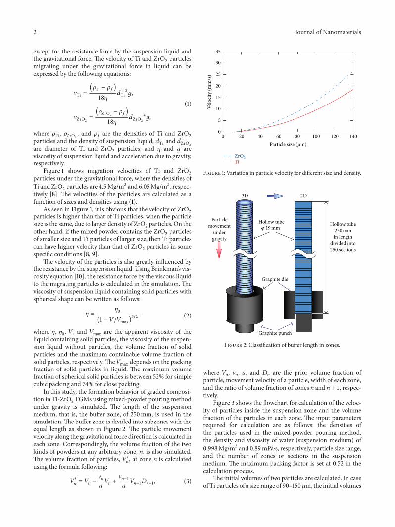
In this study the formation behavior of graded composi-tion in Ti-ZrO
2FGMs using mixed-powder pouring method
under gravity is simulated The length of the suspensionmedium that is the buffer zone of 250mm is used in thesimulationThe buffer zone is divided into subzones with theequal length as shown in Figure 2 The particle movementvelocity along the gravitational force direction is calculated ineach zone Correspondingly the volume fraction of the twokinds of powders at any arbitrary zone 119899 is also simulatedThe volume fraction of particles 1198811015840
119899 at zone 119899 is calculated
using the formula following
119881
1015840
119899= 119881119899minus
V119899
119886
119881119899+
V119899minus1
119886
119881119899minus1119863119899minus1 (3)
0 20 40 60 80 100 120 140
35
30
25
20
15
10
5
0
Velo
city
(mm
s)
Ti
Particle size (120583m)
ZrO2
Figure 1 Variation in particle velocity for different size and density
Graphite die
Graphite punch
Hollow tube
in lengthdivided into250 sections
Hollow tubeParticlemovement
undergravity
3D 2D
250mm120601 19mm
Figure 2 Classification of buffer length in zones
where 119881119899 V119899 119886 and 119863
119899are the prior volume fraction of
particle movement velocity of a particle width of each zoneand the ratio of volume fraction of zones 119899 and 119899 + 1 respec-tively
Figure 3 shows the flowchart for calculation of the veloc-ity of particles inside the suspension zone and the volumefraction of the particles in each zone The input parametersrequired for calculation are as follows the densities ofthe particles used in the mixed-powder pouring methodthe density and viscosity of water (suspension medium) of0998Mgm3 and 089mPasdots respectively particle size rangeand the number of zones or sections in the suspensionmedium The maximum packing factor is set at 052 in thecalculation process
The initial volumes of two particles are calculated In caseof Ti particles of a size range of 90ndash150120583m the initial volumes
Journal of Nanomaterials 3
End
Start
Input parameters
Velocity of particles in the suspension at each zone
at each zone
Time within limits
Output particle distribution
Yes
No
Initial volume fraction of Ti and ZrO2 particles
Calculation total volume fraction of Ti and ZrO2 mixed powder
Calculation volume fraction of Ti and ZrO2 particles
Figure 3 Calculation process of particle distribution in FGMs
of 90120583m and 150 120583m sized Ti powder are taken as 25 eachand the rest 50of initial volume is assumed to be the averageof 90120583m and 150 120583m that is 120120583mThe velocity of particlesat each zone is calculated based on Stokersquos law From thevelocity of the particles the volume fraction of particles iscalculated using (3) This process is repeated in the specifiedlimited time and the final particle distribution is obtained
3 Materials and Methods
For the mixed-powder pouring process homogeneouslymixed powders of Ti and ZrO
2with a volume ratio 1 1
were prepared Ti particles have an angular shape andZrO2particles have a spherical shape The details of pre-
pared homogeneous mixture with different particle sizes aredescribed in Table 1 In all the samples shown in Table 1 theaverage size of ZrO
2particles is larger than that of Ti particles
31 Preparation of SPS Specimen Agraphite diewith an innerdiameter of 20mm and a height of 40mm was used carbonsheet was placed along the inner wall of the graphite die Abottom punch was fitted tightly to one end of the graphitedie as shown in Figure 4 A hollow tube with a length of220mm made of plastic was fitted and sealed to another endof the graphite die The height of the total suspension that isthe length of the hollow tube along with the graphite die is250mmThe crushed ice with a volume of 785 times 10minus6m3 wasprepared using the ice crusher
The hollow tube was filled with the crushed ice as shownin Figure 4(a) Then prepared homogeneously mixed pow-ders were poured from the top of the crushed ice as shownin Figure 4(b)The crushed ice was allowed to melt graduallyunder isothermal conditions at 40∘C Sedimentation of Tiand ZrO
2particles proceeded along the hollow tube at the
uniform temperature The homogeneously-mixed powderspoured on the top of crushed ice will move down along thehollow tube and settle down at the bottom of the graphite dieSedimentation of the mixed powders depend on the densities
andor sizes of the particles After settlement a green bodywas obtained as shown in Figure 4(c) which was sinteredusing SPS afterwards
32 Fabrication of FGMs The SPS was carried out under thepressure of 30MPa at the sintering temperature of 1200∘CAfter sintering disc-shaped Ti-ZrO
2sample of FGMs with
20mm in diameter and 10mm in height was obtained Tocarry outmicrostructural investigation the specimenwas cutinto a cuboid shapewith dimensions of 10times 8times 5mm3 using amicrocutter Scanning electron microscope (SEM) and energy dispersive X-ray spectroscopy (EDX) were used to observethemicrostructure and evaluate the composition distributionof the fabricated FGMs respectively Further Vickers hard-ness test was conducted on the FGM samples to study themechanical property and confirm the gradient in the com-position of the fabricated FGMs
4 Results and Discussion
41 Compositional GradientsObtained by Simulation Figures5(a) 5(b) and 5(c) show the calculated volume fraction dis-tributions of Ti and ZrO
2in samples A B andC respectively
The abscissa in Figure 5 is the position in the direction ofgravity normalized by the length of composite that is 0 and 1represent the top and bottom surfaces of the FGMs respec-tively It can be seen from Figure 5 that Ti and ZrO
2dis-
tributions across the normalized position have yielded largecompositional gradient within the FGMs According to thesimulation with increase in normalized position 0 to 1 thevolume fraction of Ti decreases and ZrO
2increases which
results in a largely graded microstructure It can be also seenin the figures that the particle distribution becomes homoge-neous between normalized positions 06 and 065
42 Microstructure and Compositional Gradient of Ti-ZrO2
FGMs Photographs of Ti-ZrO2FGMs samples A B and
C are shown in Figures 6(a) 6(b) and 6(c) respectively Asshown in these figures continuous compositional gradientsmay form within these samples
Figures 7(a) 7(b) and 7(c) are the SEM images the FGMssamples A B and C respectivelyThe four SEM images ineach column show the graded structure of Ti and ZrO
2across
the normalized position that is from top to bottom of thefabricated FGMs From the four figures it can be seen that theconcentration of spherical particles increases gradually fromtop to bottom
The concentrations of Ti and ZrO2at each region were
analyzed by EDX and the volume fraction distributions of Tiand ZrO
2in Ti-ZrO
2FGMs were obtained as shown in
Figures 8(a) 8(b) and 8(c) It can be seen from these figuresthat the volume fraction of Ti is close to 100 between thenormalized positions of 0 and 02 in all the samples Thecomposition of Ti decreases and that of ZrO
2increases
continuously and gradually to become nearly homogeneousbetween normalized positions of 06 and 065 The volumefraction of ZrO
2reaches close to 100 between the nor-
malized positions 08 and 1 as shown in Figures 8(a) and8(b) Therefore it is found that the mixed-powder pouring
4 Journal of Nanomaterials
Graphite die
Graphite punch
Hollow tube
Crushed ice
Sealant to avoidwater leakage
(a)
Hollow tubecontainingcrushed ice
Homogeneousmixed powder
(Ti + ZrO2 particles)
(b)
Drying the mixed powder in drying
Graphitedie
Graphite punch
Hollow tubecontaining
crushedice
Homogeneousmixed powder
particles)
Sealantto avoid
water leakage
Hollowtube
containingwater
SPS
(Ti + ZrO2
machine at 40∘C
(c)
Figure 4 Experimental setup (a) pouring crushed ice into hollow tube (b) pouring homogeneous Ti-ZrO2mixed powder into hollow tube
containing crushed ice and (c) process involved in preparation of green body
Table 1 Samples prepared in this study
Particle Density Mass Sample A Sample B Sample CZrO2 6050 kgm3 951 g 75ndash106 120583m 38ndash75 120583m 106ndash150 120583mTi 4500 kgm3 707 g 63ndash90 120583m 45120583m pass 90ndash150 120583m
method is an effective fabrication technique for FGMs withlarge and continuous compositional gradient However fromthe results shown in Figure 8(c) it can be observed that thevolume fraction of ZrO
2fails to reach 100 near the normal-
ized position 1 where the large compositional gradient is notobserved because of small migration speed difference be-tween Ti and ZrO
2particles The larger buffer zone is neces-
sary for obtaining the larger compositional gradient insample C
Figure 9 shows the X-ray diffraction (XRD) pattern fromthe ZrO
2surface in sample A At the ZrO
2surface peaks
for ZrO2(tetragonal) and no peak for Ti can be seen
which means that 100 ZrO2layer formed at one side It is
considered that FGMs with 100 ZrO2at one side and 100
Journal of Nanomaterials 5
0
20
40
60
80
100
Volu
me f
ract
ion
(vol
)
0 02 04 06 08 1Normalized position (top to bottom)
TiZrO2
(a)
0
20
40
60
80
0 02 04 06 08 1Normalized position (top to bottom)
TiZrO2
Volu
me f
ract
ion
(vol
)
100
(b)
0
20
40
60
80
0 02 04 06 08 1Normalized position (top to bottom)
Ti
Volu
me f
ract
ion
(vol
)
ZrO2
100
(c)
Figure 5 Calculated volume fractions of Ti and ZrO2in Ti-ZrO
2FGMs (a) sample A (b) sample B and (c) sample C
(a)
Top to bottom
(b) (c)
Figure 6 Photographs of Ti-ZrO2FGMs samples (a) sample A (b) sample B and (c) sample C
6 Journal of Nanomaterials
(C)
200120583m
(A)
120583m200
(B)
200120583m
(a)
(C)
200120583m
(A)
200120583m
(B)
200120583m
(b)
(C)
200120583m
(A)
200120583m
(B)
200120583m
(c)
(C)
200120583m
(A)
200120583m
(B)
200120583m
(d)
Figure 7 SEM photographs of microstructure of Ti-ZrO2FGMs for (A) sample A (B) sample B and (C) sample C Photographs of (X-a)
(X-b) (X-c) and (X-d) are taken at normalized position of 00 to 025 025 to 05 05 to 075 and 075 to 10 respectively
Ti at another side can be obtained with a suitable selection ofpowder sizes and buffer zone length
43 Hardness The hardness values in Ti-ZrO2FGMs sam-
ples A B and C are also shown in Figures 8(a) 8(b)and 8(c) respectively The Vickers hardness (Hv) of Ti and
ZrO2ranges between 200ndash300 and 1200ndash1300 respectively It
was concluded in [11] that SPS has the potential of enhanceddensification and suppressed grain growth due to a fastheating rate and apparent low firing temperature Thereforethe actual hardness measured in the fabricated FGMs is onthe slightly higher side The hardness inside the fabricated
Journal of Nanomaterials 7
0
20
40
60
80
100
0 02 04 06 08 1Normalized position (top to bottom)
Ti (simulation)
0
280
560
840
1120
1400
Ti (experiment)Vickers hardness
Vick
ers h
ardn
ess (
HV
)
Volu
me f
ract
ion
(vol
)
ZrO2 (experiment)ZrO2 (simulation)
(a)
0
20
40
60
80
100
0 02 04 06 08 1Normalized position (top to bottom)
0
280
560
840
1120
Vick
ers h
ardn
ess (
HV
)
Volu
me f
ract
ion
(vol
)
Ti (simulation)
Ti (experiment)Vickers hardnessZrO2 (experiment)ZrO2 (simulation)
1400
(b)
0
20
40
60
80
0 02 04 06 08 1Normalized position (top to bottom)
0
280
560
840
1120
Vick
ers h
ardn
ess (
HV
)
Volu
me f
ract
ion
(vol
)
Ti (simulation)
Ti (experiment)Vickers hardnessZrO2 (experiment)ZrO2 (simulation)
100 1400
(c)
Figure 8 Comparison of experimental volume fraction results with simulation results and effects of hardness number in Ti-ZrO2FGMs (a)
sample A (b) sample B and (c) sample C
0 50
ZrO
100 150
Inte
nsity
(au
)
ZrO2 (tetragonal)ZrO2 (monoclinic)
2120579 (∘)
Figure 9 XRD pattern from the ZrO2surface in sample A
8 Journal of Nanomaterials
FGMs increases with the increase in normalized position 0to 1 thereby confirming the increasing ZrO
2content across
the normalized position
5 Conclusions
In this study FGMs were fabricated using a mixed-powderpouring method followed by SPS The desired continuouscompositional gradient with 100 Ti at one side and 100ZrO2at another side in the Ti-ZrO
2FGMs was obtained
Numerical simulation considerably represented experimen-tal results which can be used to select suitable sizes ofpowders and experimental conditions to obtain predesignedcompositional gradients in the FGMs
Acknowledgments
This work is supported by Regional Innovation ClusterProgram (Gifu Technical Innovation Program Japan) ofthe Ministry of Education Culture Sports Science andTechnology of Japan H Sato and Y Watanabe gratefullyacknowledge the financial support from The Light MetalEducational Foundation Inc of Japan The authors are alsograteful to Ms Motoko Yamada for her helpful work incarrying out the experiments
References
[1] T Hirai ldquoMaterials science and technologyrdquo in Processing ofCeramics R J Brook Ed vol 17 p 293 VCHWeinheim FRG
[2] S Suresh and A Mortensen Fundamentals of FunctionallyGraded Materials Processing and Thermomechanical BehaviourofGradedMetals andMetal-CeramicComposites IOMCommu-nications London UK 1998
[3] Y Miyamoto W A Kaysser B H Rabin A Kawasaki and RG Ford Eds Functionally GradedMaterials Design Processingand Applications Kluwer Academic New York NY USA 1999
[4] S Uemura Y Noda Y Shinohara and Y Watanabe EdsDevelopment and Application of Functionally Graded MaterialsCMC Publishing Tokyo Japan 2003
[5] Y Watanabe N Yamanaka and Y Fukui ldquoControl of compo-sition gradient in a metal-ceramic functionally graded materialmanufactured by the centrifugalmethodrdquoComposites A vol 29no 5-6 pp 595ndash601 1998
[6] S Li H Izui M OkanoW Zhang and TWatanabe ldquoMechan-ical properties of ZrO
2(Y2O3)-Al2O3nanocomposites with
addition of hydroxyapatite prepared by spark plasma sinteringrdquoMaterials Science Forum vol 631-632 pp 413ndash423 2010
[7] K Kinoshita H Sato and Y Watanabe ldquoDevelopment of com-positional gradient simulation for centrifugal slurry-pouringmethodsrdquo Materials Science Forum vol 631-632 pp 455ndash4602010
[8] Y Watanabe E Miura-Fujiwara and H Sato ldquoFabricationof functionally graded materials by centrifugal slurry-pouringmethod and centrifugal mixed-powder methodrdquo Journal of theJapan Society of Powder and Powder Metallurgy vol 57 no 5pp 321ndash326 2010
[9] Y Watanabe and H Sato ldquoReview fabrication of functionallygraded materials under a centrifugal forcerdquo in Nanocompositeswith Unique Properties and Applications in MedicIne and Indus-try J Cuppolitti Ed p 142 InTech Rijeka Croatia 2011
[10] H C Brinkmann ldquoThe viscosity of concentrated suspensionsand solutionsrdquoThe Journal of Chemical Physics vol 20 no 4 p571 1952
[11] T Takeuchi ldquoPreparation of electric-functional ceramics byspark-plasma-sintering methodrdquo Journal of High TemperatureSociety vol 31 no 4 p 186 2005
Submit your manuscripts athttpwwwhindawicom
ScientificaHindawi Publishing Corporationhttpwwwhindawicom Volume 2014
CorrosionInternational Journal of
Hindawi Publishing Corporationhttpwwwhindawicom Volume 2014
Polymer ScienceInternational Journal of
Hindawi Publishing Corporationhttpwwwhindawicom Volume 2014
Hindawi Publishing Corporationhttpwwwhindawicom Volume 2014
CeramicsJournal of
Hindawi Publishing Corporationhttpwwwhindawicom Volume 2014
CompositesJournal of
NanoparticlesJournal of
Hindawi Publishing Corporationhttpwwwhindawicom Volume 2014
Hindawi Publishing Corporationhttpwwwhindawicom Volume 2014
International Journal of
Biomaterials
Hindawi Publishing Corporationhttpwwwhindawicom Volume 2014
NanoscienceJournal of
TextilesHindawi Publishing Corporation httpwwwhindawicom Volume 2014
Journal of
NanotechnologyHindawi Publishing Corporationhttpwwwhindawicom Volume 2014
Journal of
CrystallographyJournal of
Hindawi Publishing Corporationhttpwwwhindawicom Volume 2014
The Scientific World JournalHindawi Publishing Corporation httpwwwhindawicom Volume 2014
Hindawi Publishing Corporationhttpwwwhindawicom Volume 2014
CoatingsJournal of
Advances in
Materials Science and EngineeringHindawi Publishing Corporationhttpwwwhindawicom Volume 2014
Smart Materials Research
Hindawi Publishing Corporationhttpwwwhindawicom Volume 2014
Hindawi Publishing Corporationhttpwwwhindawicom Volume 2014
MetallurgyJournal of
Hindawi Publishing Corporationhttpwwwhindawicom Volume 2014
BioMed Research International
MaterialsJournal of
Hindawi Publishing Corporationhttpwwwhindawicom Volume 2014
Nano
materials
Hindawi Publishing Corporationhttpwwwhindawicom Volume 2014
Journal ofNanomaterials
2 Journal of Nanomaterials
except for the resistance force by the suspension liquid andthe gravitational force The velocity of Ti and ZrO
2particles
migrating under the gravitational force in liquid can beexpressed by the following equations
VTi =(120588Ti minus 120588119891)
18120578
119889Ti2119892
VZrO2
=
(120588ZrO2
minus 120588119891)
18120578
119889ZrO2
2119892
(1)
where 120588Ti 120588ZrO2
and 120588119891are the densities of Ti and ZrO
2
particles and the density of suspension liquid 119889Ti and 119889ZrO2
are diameter of Ti and ZrO2particles and 120578 and 119892 are
viscosity of suspension liquid and acceleration due to gravityrespectively
Figure 1 shows migration velocities of Ti and ZrO2
particles under the gravitational force where the densities ofTi and ZrO
2particles are 45Mgm3 and 605Mgm3 respec-
tively [8] The velocities of the particles are calculated as afunction of sizes and densities using (1)
As seen in Figure 1 it is obvious that the velocity of ZrO2
particles is higher than that of Ti particles when the particlesize is the same due to larger density of ZrO
2particles On the
other hand if the mixed powder contains the ZrO2particles
of smaller size and Ti particles of larger size then Ti particlescan have higher velocity than that of ZrO
2particles in some
specific conditions [8 9]The velocity of the particles is also greatly influenced by
the resistance by the suspension liquid Using Brinkmanrsquos vis-cosity equation [10] the resistance force by the viscous liquidto the migrating particles is calculated in the simulation Theviscosity of suspension liquid containing solid particles withspherical shape can be written as follows
120578 =
1205780
(1 minus 119881119881max)52 (2)
where 120578 1205780 119881 and 119881max are the apparent viscosity of the
liquid containing solid particles the viscosity of the suspen-sion liquid without particles the volume fraction of solidparticles and the maximum containable volume fraction ofsolid particles respectivelyThe119881max depends on the packingfraction of solid particles in liquid The maximum volumefraction of spherical solid particles is between 52 for simplecubic packing and 74 for close packing
In this study the formation behavior of graded composi-tion in Ti-ZrO
2FGMs using mixed-powder pouring method
under gravity is simulated The length of the suspensionmedium that is the buffer zone of 250mm is used in thesimulationThe buffer zone is divided into subzones with theequal length as shown in Figure 2 The particle movementvelocity along the gravitational force direction is calculated ineach zone Correspondingly the volume fraction of the twokinds of powders at any arbitrary zone 119899 is also simulatedThe volume fraction of particles 1198811015840
119899 at zone 119899 is calculated
using the formula following
119881
1015840
119899= 119881119899minus
V119899
119886
119881119899+
V119899minus1
119886
119881119899minus1119863119899minus1 (3)
0 20 40 60 80 100 120 140
35
30
25
20
15
10
5
0
Velo
city
(mm
s)
Ti
Particle size (120583m)
ZrO2
Figure 1 Variation in particle velocity for different size and density
Graphite die
Graphite punch
Hollow tube
in lengthdivided into250 sections
Hollow tubeParticlemovement
undergravity
3D 2D
250mm120601 19mm
Figure 2 Classification of buffer length in zones
where 119881119899 V119899 119886 and 119863
119899are the prior volume fraction of
particle movement velocity of a particle width of each zoneand the ratio of volume fraction of zones 119899 and 119899 + 1 respec-tively
Figure 3 shows the flowchart for calculation of the veloc-ity of particles inside the suspension zone and the volumefraction of the particles in each zone The input parametersrequired for calculation are as follows the densities ofthe particles used in the mixed-powder pouring methodthe density and viscosity of water (suspension medium) of0998Mgm3 and 089mPasdots respectively particle size rangeand the number of zones or sections in the suspensionmedium The maximum packing factor is set at 052 in thecalculation process
The initial volumes of two particles are calculated In caseof Ti particles of a size range of 90ndash150120583m the initial volumes
Journal of Nanomaterials 3
End
Start
Input parameters
Velocity of particles in the suspension at each zone
at each zone
Time within limits
Output particle distribution
Yes
No
Initial volume fraction of Ti and ZrO2 particles
Calculation total volume fraction of Ti and ZrO2 mixed powder
Calculation volume fraction of Ti and ZrO2 particles
Figure 3 Calculation process of particle distribution in FGMs
of 90120583m and 150 120583m sized Ti powder are taken as 25 eachand the rest 50of initial volume is assumed to be the averageof 90120583m and 150 120583m that is 120120583mThe velocity of particlesat each zone is calculated based on Stokersquos law From thevelocity of the particles the volume fraction of particles iscalculated using (3) This process is repeated in the specifiedlimited time and the final particle distribution is obtained
3 Materials and Methods
For the mixed-powder pouring process homogeneouslymixed powders of Ti and ZrO
2with a volume ratio 1 1
were prepared Ti particles have an angular shape andZrO2particles have a spherical shape The details of pre-
pared homogeneous mixture with different particle sizes aredescribed in Table 1 In all the samples shown in Table 1 theaverage size of ZrO
2particles is larger than that of Ti particles
31 Preparation of SPS Specimen Agraphite diewith an innerdiameter of 20mm and a height of 40mm was used carbonsheet was placed along the inner wall of the graphite die Abottom punch was fitted tightly to one end of the graphitedie as shown in Figure 4 A hollow tube with a length of220mm made of plastic was fitted and sealed to another endof the graphite die The height of the total suspension that isthe length of the hollow tube along with the graphite die is250mmThe crushed ice with a volume of 785 times 10minus6m3 wasprepared using the ice crusher
The hollow tube was filled with the crushed ice as shownin Figure 4(a) Then prepared homogeneously mixed pow-ders were poured from the top of the crushed ice as shownin Figure 4(b)The crushed ice was allowed to melt graduallyunder isothermal conditions at 40∘C Sedimentation of Tiand ZrO
2particles proceeded along the hollow tube at the
uniform temperature The homogeneously-mixed powderspoured on the top of crushed ice will move down along thehollow tube and settle down at the bottom of the graphite dieSedimentation of the mixed powders depend on the densities
andor sizes of the particles After settlement a green bodywas obtained as shown in Figure 4(c) which was sinteredusing SPS afterwards
32 Fabrication of FGMs The SPS was carried out under thepressure of 30MPa at the sintering temperature of 1200∘CAfter sintering disc-shaped Ti-ZrO
2sample of FGMs with
20mm in diameter and 10mm in height was obtained Tocarry outmicrostructural investigation the specimenwas cutinto a cuboid shapewith dimensions of 10times 8times 5mm3 using amicrocutter Scanning electron microscope (SEM) and energy dispersive X-ray spectroscopy (EDX) were used to observethemicrostructure and evaluate the composition distributionof the fabricated FGMs respectively Further Vickers hard-ness test was conducted on the FGM samples to study themechanical property and confirm the gradient in the com-position of the fabricated FGMs
4 Results and Discussion
41 Compositional GradientsObtained by Simulation Figures5(a) 5(b) and 5(c) show the calculated volume fraction dis-tributions of Ti and ZrO
2in samples A B andC respectively
The abscissa in Figure 5 is the position in the direction ofgravity normalized by the length of composite that is 0 and 1represent the top and bottom surfaces of the FGMs respec-tively It can be seen from Figure 5 that Ti and ZrO
2dis-
tributions across the normalized position have yielded largecompositional gradient within the FGMs According to thesimulation with increase in normalized position 0 to 1 thevolume fraction of Ti decreases and ZrO
2increases which
results in a largely graded microstructure It can be also seenin the figures that the particle distribution becomes homoge-neous between normalized positions 06 and 065
42 Microstructure and Compositional Gradient of Ti-ZrO2
FGMs Photographs of Ti-ZrO2FGMs samples A B and
C are shown in Figures 6(a) 6(b) and 6(c) respectively Asshown in these figures continuous compositional gradientsmay form within these samples
Figures 7(a) 7(b) and 7(c) are the SEM images the FGMssamples A B and C respectivelyThe four SEM images ineach column show the graded structure of Ti and ZrO
2across
the normalized position that is from top to bottom of thefabricated FGMs From the four figures it can be seen that theconcentration of spherical particles increases gradually fromtop to bottom
The concentrations of Ti and ZrO2at each region were
analyzed by EDX and the volume fraction distributions of Tiand ZrO
2in Ti-ZrO
2FGMs were obtained as shown in
Figures 8(a) 8(b) and 8(c) It can be seen from these figuresthat the volume fraction of Ti is close to 100 between thenormalized positions of 0 and 02 in all the samples Thecomposition of Ti decreases and that of ZrO
2increases
continuously and gradually to become nearly homogeneousbetween normalized positions of 06 and 065 The volumefraction of ZrO
2reaches close to 100 between the nor-
malized positions 08 and 1 as shown in Figures 8(a) and8(b) Therefore it is found that the mixed-powder pouring
4 Journal of Nanomaterials
Graphite die
Graphite punch
Hollow tube
Crushed ice
Sealant to avoidwater leakage
(a)
Hollow tubecontainingcrushed ice
Homogeneousmixed powder
(Ti + ZrO2 particles)
(b)
Drying the mixed powder in drying
Graphitedie
Graphite punch
Hollow tubecontaining
crushedice
Homogeneousmixed powder
particles)
Sealantto avoid
water leakage
Hollowtube
containingwater
SPS
(Ti + ZrO2
machine at 40∘C
(c)
Figure 4 Experimental setup (a) pouring crushed ice into hollow tube (b) pouring homogeneous Ti-ZrO2mixed powder into hollow tube
containing crushed ice and (c) process involved in preparation of green body
Table 1 Samples prepared in this study
Particle Density Mass Sample A Sample B Sample CZrO2 6050 kgm3 951 g 75ndash106 120583m 38ndash75 120583m 106ndash150 120583mTi 4500 kgm3 707 g 63ndash90 120583m 45120583m pass 90ndash150 120583m
method is an effective fabrication technique for FGMs withlarge and continuous compositional gradient However fromthe results shown in Figure 8(c) it can be observed that thevolume fraction of ZrO
2fails to reach 100 near the normal-
ized position 1 where the large compositional gradient is notobserved because of small migration speed difference be-tween Ti and ZrO
2particles The larger buffer zone is neces-
sary for obtaining the larger compositional gradient insample C
Figure 9 shows the X-ray diffraction (XRD) pattern fromthe ZrO
2surface in sample A At the ZrO
2surface peaks
for ZrO2(tetragonal) and no peak for Ti can be seen
which means that 100 ZrO2layer formed at one side It is
considered that FGMs with 100 ZrO2at one side and 100
Journal of Nanomaterials 5
0
20
40
60
80
100
Volu
me f
ract
ion
(vol
)
0 02 04 06 08 1Normalized position (top to bottom)
TiZrO2
(a)
0
20
40
60
80
0 02 04 06 08 1Normalized position (top to bottom)
TiZrO2
Volu
me f
ract
ion
(vol
)
100
(b)
0
20
40
60
80
0 02 04 06 08 1Normalized position (top to bottom)
Ti
Volu
me f
ract
ion
(vol
)
ZrO2
100
(c)
Figure 5 Calculated volume fractions of Ti and ZrO2in Ti-ZrO
2FGMs (a) sample A (b) sample B and (c) sample C
(a)
Top to bottom
(b) (c)
Figure 6 Photographs of Ti-ZrO2FGMs samples (a) sample A (b) sample B and (c) sample C
6 Journal of Nanomaterials
(C)
200120583m
(A)
120583m200
(B)
200120583m
(a)
(C)
200120583m
(A)
200120583m
(B)
200120583m
(b)
(C)
200120583m
(A)
200120583m
(B)
200120583m
(c)
(C)
200120583m
(A)
200120583m
(B)
200120583m
(d)
Figure 7 SEM photographs of microstructure of Ti-ZrO2FGMs for (A) sample A (B) sample B and (C) sample C Photographs of (X-a)
(X-b) (X-c) and (X-d) are taken at normalized position of 00 to 025 025 to 05 05 to 075 and 075 to 10 respectively
Ti at another side can be obtained with a suitable selection ofpowder sizes and buffer zone length
43 Hardness The hardness values in Ti-ZrO2FGMs sam-
ples A B and C are also shown in Figures 8(a) 8(b)and 8(c) respectively The Vickers hardness (Hv) of Ti and
ZrO2ranges between 200ndash300 and 1200ndash1300 respectively It
was concluded in [11] that SPS has the potential of enhanceddensification and suppressed grain growth due to a fastheating rate and apparent low firing temperature Thereforethe actual hardness measured in the fabricated FGMs is onthe slightly higher side The hardness inside the fabricated
Journal of Nanomaterials 7
0
20
40
60
80
100
0 02 04 06 08 1Normalized position (top to bottom)
Ti (simulation)
0
280
560
840
1120
1400
Ti (experiment)Vickers hardness
Vick
ers h
ardn
ess (
HV
)
Volu
me f
ract
ion
(vol
)
ZrO2 (experiment)ZrO2 (simulation)
(a)
0
20
40
60
80
100
0 02 04 06 08 1Normalized position (top to bottom)
0
280
560
840
1120
Vick
ers h
ardn
ess (
HV
)
Volu
me f
ract
ion
(vol
)
Ti (simulation)
Ti (experiment)Vickers hardnessZrO2 (experiment)ZrO2 (simulation)
1400
(b)
0
20
40
60
80
0 02 04 06 08 1Normalized position (top to bottom)
0
280
560
840
1120
Vick
ers h
ardn
ess (
HV
)
Volu
me f
ract
ion
(vol
)
Ti (simulation)
Ti (experiment)Vickers hardnessZrO2 (experiment)ZrO2 (simulation)
100 1400
(c)
Figure 8 Comparison of experimental volume fraction results with simulation results and effects of hardness number in Ti-ZrO2FGMs (a)
sample A (b) sample B and (c) sample C
0 50
ZrO
100 150
Inte
nsity
(au
)
ZrO2 (tetragonal)ZrO2 (monoclinic)
2120579 (∘)
Figure 9 XRD pattern from the ZrO2surface in sample A
8 Journal of Nanomaterials
FGMs increases with the increase in normalized position 0to 1 thereby confirming the increasing ZrO
2content across
the normalized position
5 Conclusions
In this study FGMs were fabricated using a mixed-powderpouring method followed by SPS The desired continuouscompositional gradient with 100 Ti at one side and 100ZrO2at another side in the Ti-ZrO
2FGMs was obtained
Numerical simulation considerably represented experimen-tal results which can be used to select suitable sizes ofpowders and experimental conditions to obtain predesignedcompositional gradients in the FGMs
Acknowledgments
This work is supported by Regional Innovation ClusterProgram (Gifu Technical Innovation Program Japan) ofthe Ministry of Education Culture Sports Science andTechnology of Japan H Sato and Y Watanabe gratefullyacknowledge the financial support from The Light MetalEducational Foundation Inc of Japan The authors are alsograteful to Ms Motoko Yamada for her helpful work incarrying out the experiments
References
[1] T Hirai ldquoMaterials science and technologyrdquo in Processing ofCeramics R J Brook Ed vol 17 p 293 VCHWeinheim FRG
[2] S Suresh and A Mortensen Fundamentals of FunctionallyGraded Materials Processing and Thermomechanical BehaviourofGradedMetals andMetal-CeramicComposites IOMCommu-nications London UK 1998
[3] Y Miyamoto W A Kaysser B H Rabin A Kawasaki and RG Ford Eds Functionally GradedMaterials Design Processingand Applications Kluwer Academic New York NY USA 1999
[4] S Uemura Y Noda Y Shinohara and Y Watanabe EdsDevelopment and Application of Functionally Graded MaterialsCMC Publishing Tokyo Japan 2003
[5] Y Watanabe N Yamanaka and Y Fukui ldquoControl of compo-sition gradient in a metal-ceramic functionally graded materialmanufactured by the centrifugalmethodrdquoComposites A vol 29no 5-6 pp 595ndash601 1998
[6] S Li H Izui M OkanoW Zhang and TWatanabe ldquoMechan-ical properties of ZrO
2(Y2O3)-Al2O3nanocomposites with
addition of hydroxyapatite prepared by spark plasma sinteringrdquoMaterials Science Forum vol 631-632 pp 413ndash423 2010
[7] K Kinoshita H Sato and Y Watanabe ldquoDevelopment of com-positional gradient simulation for centrifugal slurry-pouringmethodsrdquo Materials Science Forum vol 631-632 pp 455ndash4602010
[8] Y Watanabe E Miura-Fujiwara and H Sato ldquoFabricationof functionally graded materials by centrifugal slurry-pouringmethod and centrifugal mixed-powder methodrdquo Journal of theJapan Society of Powder and Powder Metallurgy vol 57 no 5pp 321ndash326 2010
[9] Y Watanabe and H Sato ldquoReview fabrication of functionallygraded materials under a centrifugal forcerdquo in Nanocompositeswith Unique Properties and Applications in MedicIne and Indus-try J Cuppolitti Ed p 142 InTech Rijeka Croatia 2011
[10] H C Brinkmann ldquoThe viscosity of concentrated suspensionsand solutionsrdquoThe Journal of Chemical Physics vol 20 no 4 p571 1952
[11] T Takeuchi ldquoPreparation of electric-functional ceramics byspark-plasma-sintering methodrdquo Journal of High TemperatureSociety vol 31 no 4 p 186 2005
Submit your manuscripts athttpwwwhindawicom
ScientificaHindawi Publishing Corporationhttpwwwhindawicom Volume 2014
CorrosionInternational Journal of
Hindawi Publishing Corporationhttpwwwhindawicom Volume 2014
Polymer ScienceInternational Journal of
Hindawi Publishing Corporationhttpwwwhindawicom Volume 2014
Hindawi Publishing Corporationhttpwwwhindawicom Volume 2014
CeramicsJournal of
Hindawi Publishing Corporationhttpwwwhindawicom Volume 2014
CompositesJournal of
NanoparticlesJournal of
Hindawi Publishing Corporationhttpwwwhindawicom Volume 2014
Hindawi Publishing Corporationhttpwwwhindawicom Volume 2014
International Journal of
Biomaterials
Hindawi Publishing Corporationhttpwwwhindawicom Volume 2014
NanoscienceJournal of
TextilesHindawi Publishing Corporation httpwwwhindawicom Volume 2014
Journal of
NanotechnologyHindawi Publishing Corporationhttpwwwhindawicom Volume 2014
Journal of
CrystallographyJournal of
Hindawi Publishing Corporationhttpwwwhindawicom Volume 2014
The Scientific World JournalHindawi Publishing Corporation httpwwwhindawicom Volume 2014
Hindawi Publishing Corporationhttpwwwhindawicom Volume 2014
CoatingsJournal of
Advances in
Materials Science and EngineeringHindawi Publishing Corporationhttpwwwhindawicom Volume 2014
Smart Materials Research
Hindawi Publishing Corporationhttpwwwhindawicom Volume 2014
Hindawi Publishing Corporationhttpwwwhindawicom Volume 2014
MetallurgyJournal of
Hindawi Publishing Corporationhttpwwwhindawicom Volume 2014
BioMed Research International
MaterialsJournal of
Hindawi Publishing Corporationhttpwwwhindawicom Volume 2014
Nano
materials
Hindawi Publishing Corporationhttpwwwhindawicom Volume 2014
Journal ofNanomaterials

![ars.els-cdn.com · Web view[89] HDPE 125000 350 3.55 60 0.5%Pt/SO 4 /ZrO 2 2:1 64.7s [89] HDPE 125000 350 3.55 60 0.5%Pt/SO 4 /ZrO 2 5:1 55.1s [89] HDPE 125000 375 8.38 25 2.0%Ni/ZrO](https://img.pdfslide.us/doc/110x75/5f57a2ddb78beb754767c28c/arsels-cdncom-web-view-89-hdpe-125000-350-355-60-05ptso-4-zro-2-21-647s.jpg)