Embed Size (px)
Citation preview
Research ArticleExperimental Characterization of the Twin-EyeLaser Mouse Sensor
Javier Moreno,1 Eduard Clotet,1 Dani Martínez,1 Marcel Tresanchez,1
Tomàs Pallejà,2 and Jordi Palacín1
1Department of Computer Science and Industrial Engineering, University of Lleida, Jaume II 69, 25001 Lleida, Spain2Barton Laboratory, Cornell University, Geneva, NY 14456, USA
Correspondence should be addressed to Jordi Palacın; [email protected]
Received 14 July 2016; Accepted 20 September 2016
Academic Editor: Vincenzo Spagnolo
Copyright © 2016 Javier Moreno et al. This is an open access article distributed under the Creative Commons Attribution License,which permits unrestricted use, distribution, and reproduction in any medium, provided the original work is properly cited.
This paper proposes the experimental characterization of a laser mouse sensor used in some optical mouse devices. The sensorcharacterized is called twin-eye laser mouse sensor and uses the Doppler effect to measure displacement as an alternative tooptical flow-based mouse sensors. The experimental characterization showed similar measurement performances to optical flowsensors except in the sensitivity to height changes and whenmeasuring nonlinear displacements, where the twin-eye sensor offeredbetter performance.The measurement principle of this optical sensor can be applied to the development of alternative inexpensiveapplications that require planar displacement measurement and poor sensitivity to 𝑧-axis changes such as mobile robotics.
1. Introduction
The computer mouse, introduced in the 1960s, is currentlythe main human computer interface device. It is an elec-tronic device held with one hand that is displaced over asupporting surface and translates these displacements intocursor displacements on a computer screen. In the first deviceimplementations, the displacement of the surface under themouse was measured by using mechanical wheels and therotation of a ball whereas current versions measure surfacedisplacement by using integrated optical sensors, such asoptical flow sensors and Doppler sensors.
The optical flow sensors [1, 2] measure displacement byusing an imaging device pointed at the supporting surfaceand a digital signal processing (DSP) unit that computesthe optical flow of the images acquired. These sensors alsoincorporate an external or internal LED (or laser LED)device to provide custom and controlled illumination to thesupporting surface under the sensor.
There are a huge number of research works related tothe analysis and application of optical flow sensors. In [3–5], some specific optical flow sensors were evaluated as a
two-dimensional displacement sensor, in [6] as a trajectorytracking, and in [5, 7–11] as odometry sensors for robotics.In [3], an optical flow sensor was tested as a displacementsensor with good linearity over opaque objects. In [5], alinear displacement was measured with a coefficient ofdetermination, 𝑅2, of 0.99 but obtaining an error of 1% inthe measurement in the case of an offset of 0.1mm in therelative height of the sensor and also inaccuracies in circulardisplacements which prone its direct application as trajectorysensor in mobile robotics [12]. In [9], the effect of lateralillumination was analyzed as an error source in odometryapplications. In [10], differential optical navigation by usingtwo optical flow sensors was proposed to improve the errorin the variation of the height, obtaining a maximum errorof 1.38% for a height offset of 20mm. In [11], multipleoptical flow sensors were proposed to improve odometryaccuracy when measuring circular displacements. Similarly,a localization system for microaerial vehicles is proposed in[13] combining an optical flow sensor with an inertialnavigation system and a magnetometer. Additionally, theimage acquired by the optical flow sensor was used in [14–19] to develop specific low-cost image-based applications.
Hindawi Publishing CorporationJournal of SensorsVolume 2016, Article ID 4281397, 8 pageshttp://dx.doi.org/10.1155/2016/4281397

2 Journal of Sensors
Figure 1: The twin-eye laser sensor, with and without lens packaging (courtesy of Philips [28]).
Surface
Laser and detector
LensHeight
𝜑
�
Figure 2: Working principle of the twin-eye laser sensor.
For example, in [20], an optical mouse sensor was used toperform Optical Coherence Tomography for manual imagescanning.
Doppler sensors [21–25] measure displacement based onthe Doppler effect by comparing the shifted phase modula-tion of the reflected light relative to the original laser light[25–27]. The velocity of the motion is proportional to theDoppler shift and the displacement is obtained by integratingthe velocity into a planemovement over time. In the twin-eyeoptical sensor, two independent self-mixing lasers are used tomeasure displacement in both 𝑥-axis and 𝑦-axis [23].
The new contribution of this work is the experimentalcharacterization of the optical twin-eye laser sensor as a two-axis displacement sensor. The results obtained are comparedwith the performances of optical flow-based sensors.
2. The Twin-Eye Laser Sensor
The twin-eye laser sensor provided by Philips (Figure 1) [28]is a compact motion sensor (6.86mm square and 3.86mmhigh) based on two independent self-mixing Vertical-Cavity-Surface-Emitting Lasers [27] (VCSELs) for surface tracking[24, 25] on two axes; each laser is used to emit and receive thereflected light. The sensor device includes a DSP, two solid-state lasers, and plastic lenses integrated into the same chip[24].
The working principle of the twin-eye sensor is based onsensing the small portion of scattered infrared light emittedby the laser that is reflected back (into the same emittingcavity) by the surface (Figure 2). When the device is movedalong the surface, a shift in the frequency of the returning
laser light compared with the original light is generatedfor each independent laser [25–27]. This effect, called theDoppler effect, produces a periodic variation at a constantemitted frequency, defined as the Doppler frequency:
𝑓Doppler =2 ⋅ V ⋅ cos (𝜑)𝜆, (1)
where 𝑓Doppler is the Doppler frequency, 𝜑 is the relativeangular orientation of the laser (fixed by the package), V isthe velocity component along the direction of the laser beam,and 𝜆 is the wavelength of the laser. An internal DSP convertsthe Doppler frequency into instantaneous velocity and thenthe displacement is obtained by integrating this velocity overtime.
The Doppler shift frequency does not yield informationabout the motion direction. To this end, the emitted lightis modulated with a low-frequency triangular waveformand then the direction of the displacement is obtained bycomparing the Doppler shift in the rising and falling slopesof the triangular modulation [22].
The sensor analyzed in this work is the PLN3032 modelthat, according to themanufacturer, is a high precision sensorwith an independent resolution programming for the 𝑥-axis and 𝑦-axis. The main characteristics are a configuredresolution from 125 up to 4,000 counts per inch (CPI) insteps of 125 CPI, maximum supported speed of 1.5m/s,maximumacceleration of 50 g, and recommended distance tothe surface of 2.3mm (Figure 2) (the height range is from 2.1to 2.5mm).The sensor can be accessed by reading andwritingthe internal registers through the Serial Peripheral Interface(SPI) bus.
The main internal registers are the Status, Delta 𝑋, andDelta 𝑌, all with 16 bits. The Delta registers have 16 bits butonly 10 bits are used to represent the displacement in both𝑋 and 𝑌 axes since the last reading using a two’s complementrepresentation. The Status register has several bits indicatingif an internal error has occurred during operation, if an over-flow in the Delta registers has occurred, if a movement hasbeen detected, and if the sensor has been lifted. Finally, thereis a register to configure the resolution of the displacementfor each independent axis.
Journal of Sensors 3
Y
X
r
d
Sensor bottom view
XY
T1
T2
T3
𝛼45∘
X
Y
Y
X
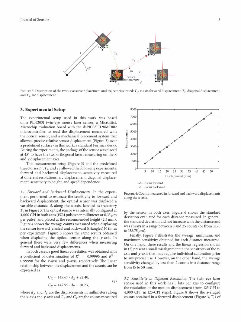
Figure 3: Description of the twin-eye sensor placement and trajectories tested: 𝑇1, 𝑥-axis forward displacement, 𝑇
2, diagonal displacement,
and 𝑇3, arc displacement.
3. Experimental Setup
The experimental setup used in this work was basedon a PLN2031 twin-eye mouse laser sensor, a MicrostickMicrochip evaluation board with the dsPIC33FJ128MC802microcontroller to read the displacement measured withthe optical sensor, and a mechanical placement system thatallowed precise relative sensor displacement (Figure 3) overa predefined surface (in this work, a standard Formica desk).During the experiments, the package of the sensor was placedat 45∘ to have the two orthogonal lasers measuring on the 𝑥and 𝑦 displacement axes.
This measurement setup (Figure 3) and the predefinedtrajectories 𝑇
1, 𝑇2, and 𝑇
3allowed the following experiments:
forward and backward displacement, sensitivity measuredat different resolutions, arc displacement, diagonal displace-ment, sensitivity to height, and speed dependence.
3.1. Forward and Backward Displacements. In the experi-ment performed to estimate the sensitivity to forward andbackward displacement, the optical sensor was displaced avariable distance, 𝑑, along the 𝑥-axis, labelled as trajectory𝑇1in Figure 3.The optical sensor was internally configured at
4,000 CPI in both axes (157.4 pulses permillimeter or 6.35 𝜇mper pulse) and placed at the recommended height (2.3mm).Figure 4 shows the average counts measured when displacingthe sensor forward (circles) and backward (triangles) 10 timesper experiment. Figure 5 shows the same results obtainedwhen displacing the optical sensor along the 𝑦-axis. Ingeneral there were very few differences when measuringforward and backward displacements.
In both cases, a good linear correlation was obtained witha coefficient of determination of 𝑅2 = 0.99996 and 𝑅2 =0.99998 for the 𝑥-axis and 𝑦-axis, respectively. The linearrelationship between the displacement and the counts can beexpressed as
𝐶𝑋= 149.67 ⋅ 𝑑
𝑋+ 22.40,
𝐶𝑌= 147.95 ⋅ 𝑑
𝑌+ 10.23,
(2)
where 𝑑𝑋and 𝑑
𝑌are the displacements in millimeters along
the 𝑥-axis and 𝑦-axis and𝐶𝑋and𝐶
𝑌are the countsmeasured
5 10 15 20 25 30 35 40 45 500
1000
2000
3000
4000
5000
6000
7000
8000
Displacement (mm)
Sens
or co
unts
x-axis forwardx-axis backward
Figure 4: Countsmeasured in forward and backward displacementsalong the 𝑥-axis.
by the sensor in both axes. Figure 6 shows the standarddeviation evaluated for each distance measured. In general,the standard deviation did not increase with the distance andwas always in a range between 5 and 25 counts (or from 31.75to 158.75𝜇m).
Finally, Figure 7 illustrates the average, minimum, andmaximum sensitivity obtained for each distance measured.On one hand, these results and the linear regression shownin (2) present a small misalignment in the sensitivity of the 𝑥-axis and 𝑦-axis that may require individual calibration priorto any precise use. However, on the other hand, the averagesensitivity changed by less than 2 counts in a distance rangefrom 15 to 50mm.
3.2. Sensitivity at Different Resolution. The twin-eye lasersensor used in this work has 5 bits per axis to configurethe resolution of the motion displacement (from 125 CPI to4,000 CPI, in 125-CPI steps). Figure 8 shows the averagedcounts obtained in a forward displacement (Figure 3, 𝑇
1) of

4 Journal of Sensors
5 10 15 20 25 30 35 40 45 500
1000
2000
3000
4000
5000
6000
7000
8000
Displacement (mm)
Sens
or co
unts
y-axis forwardy-axis backward
Figure 5: Countsmeasured in forward and backward displacementsalong the 𝑦-axis.
15 20 25 30 35 40 45 500
5
10
15
20
25
30
35
40
45
50
Displacement (mm)
Sens
or co
unts
x-axisy-axis
Figure 6: Evolution of the standard deviation for each distancemeasured along the 𝑥-axis and 𝑦-axis.
the optical sensor along the 𝑥-axis when using four differentresolutions: 1,000, 2,000, 3,000, and 4,000 CPI.
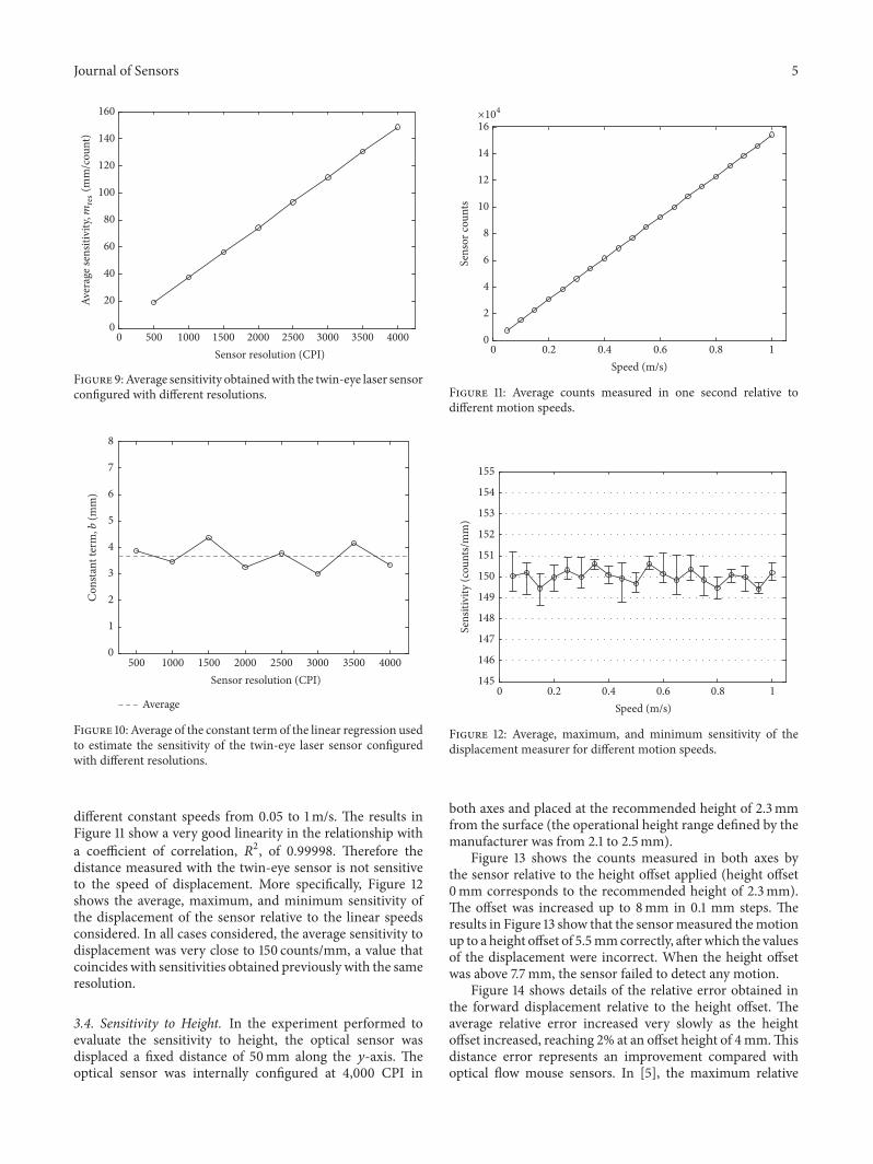
Figure 9 summarizes the sensitivity measured for a widerange of sensor resolutions. The relationship between thesensitivity and the resolution is very lineal with a coefficientof determination of 𝑅2 = 0.99998 and can be expressed as
𝑚res = 0.037108 ⋅ res + 0.2644, (3)
where res is the resolution of the optical sensor in CPI and𝑚res is the sensitivity of the sensor at that resolution. Then,the displacement in millimeters, 𝑑, generated in a forwardmovement can be estimated by using
𝑑 = 𝑚res ⋅ 𝐶 + 𝑏, (4)
15 20 25 30 35 40 45 50136138140142144146148150152154156158
Displacement (mm)
Sens
itivi
ty (c
ount
s/m
m)
x-axisy-axis
Figure 7: Average, minimum, and maximum sensitivity valuesobtained for each distance measured along the 𝑥-axis and 𝑦-axis.
0 10 20 30 40 50 600
1000
2000
3000
4000
5000
6000
7000
8000
y-axis forward displacement (mm)
Sens
or co
unts
1000CPI2000CPI
3000CPI4000CPI
Figure 8: Sensor counts obtained with the twin-eye laser sensoroperating at different resolutions.
where 𝐶 is the number of counts measured and b is theconstant term of the linear relationship. Figure 10 shows thevalue of this constant term measured along the 𝑥-axis anddifferent optical sensor resolutions. This constant term, 𝑏,has values in a narrow range between 3 and 4.5mm with anaverage value of 3.6mm.
3.3. Sensitivity to Speed. In the experiment to estimate thesensitivity to the speed of the motion, the optical sensorwas displaced along the 𝑥-axis, labelled as trajectory 𝑇
1in
Figure 3, for 1 second. The optical sensor was internallyconfigured at 4,000 CPI in both axes and placed at the recom-mended height (2.3mm). Eachmeasurement was repeated 10times.
Figure 11 presents the averaged sensor counts measuredduring 1 second while the sensor was moving forward at
Journal of Sensors 5
0 500 1000 1500 2000 2500 3000 3500 40000
20
40
60
80
100
120
140
160
Sensor resolution (CPI)
Aver
age s
ensit
ivity
,mre
s(m
m/c
ount
)
Figure 9:Average sensitivity obtainedwith the twin-eye laser sensorconfigured with different resolutions.
500 1000 1500 2000 2500 3000 3500 40000
1
2
3
4
5
6
7
8
Con
stant
term
, b (m
m)
Sensor resolution (CPI)
Average
Figure 10: Average of the constant term of the linear regression usedto estimate the sensitivity of the twin-eye laser sensor configuredwith different resolutions.
different constant speeds from 0.05 to 1m/s. The results inFigure 11 show a very good linearity in the relationship witha coefficient of correlation, 𝑅2, of 0.99998. Therefore thedistance measured with the twin-eye sensor is not sensitiveto the speed of displacement. More specifically, Figure 12shows the average, maximum, and minimum sensitivity ofthe displacement of the sensor relative to the linear speedsconsidered. In all cases considered, the average sensitivity todisplacement was very close to 150 counts/mm, a value thatcoincides with sensitivities obtained previously with the sameresolution.
3.4. Sensitivity to Height. In the experiment performed toevaluate the sensitivity to height, the optical sensor wasdisplaced a fixed distance of 50mm along the 𝑦-axis. Theoptical sensor was internally configured at 4,000 CPI in
0 0.2 0.4 0.6 0.8 10
2
4
6
8
10
12
14
16
Speed (m/s)
Sens
or co
unts
×104
Figure 11: Average counts measured in one second relative todifferent motion speeds.
0 0.2 0.4 0.6 0.8 1145
146
147
148
149
150
151
152
153
154
155
Speed (m/s)
Sens
itivi
ty (c
ount
s/m
m)
Figure 12: Average, maximum, and minimum sensitivity of thedisplacement measurer for different motion speeds.
both axes and placed at the recommended height of 2.3mmfrom the surface (the operational height range defined by themanufacturer was from 2.1 to 2.5mm).
Figure 13 shows the counts measured in both axes bythe sensor relative to the height offset applied (height offset0mm corresponds to the recommended height of 2.3mm).The offset was increased up to 8mm in 0.1 mm steps. Theresults in Figure 13 show that the sensormeasured themotionup to a height offset of 5.5mmcorrectly, afterwhich the valuesof the displacement were incorrect. When the height offsetwas above 7.7mm, the sensor failed to detect any motion.
Figure 14 shows details of the relative error obtained inthe forward displacement relative to the height offset. Theaverage relative error increased very slowly as the heightoffset increased, reaching 2% at an offset height of 4mm.Thisdistance error represents an improvement compared withoptical flow mouse sensors. In [5], the maximum relative

6 Journal of Sensors
0 1 2 3 4 5 6 7 80
2000
4000
6000
8000
10000
12000
Height offset (mm)
Sens
or co
unts
x-axisy-axis
Figure 13: Influence of the height offset on the sensor countsmeasured in forward displacements of 50mm. The 0 height offsetcorresponds to the recommended height of 2.3mm.
0 0.5 1 1.5 2 2.5 3 3.5 4 4.5 5 5.5
0
1
2
3
4
5
6
7
Height offset (mm)
Relat
ive e
rror
(%)
−1
AverageMaximum
Minimum
Figure 14: Average, minimum, and maximum relative errorobtained in a forward displacement of 50mm relative to the heightoffset.
error obtained for a height offset of 1mm in an optical flowmouse sensor was 14.37%, while it is lower than 0.2% withthe twin-eye sensor, which represents a great improvement.
3.5. Diagonal Displacement. The following experiment wasdesigned to evaluate the behavior of the sensor when it isdisplaced a fixed distance of 50mm diagonally (labelled astrajectory 𝑇
2in Figure 3) using a fixed inclination angle 𝛼.
The optical sensor was internally configured at 4,000 CPI inboth axes and placed at the recommended height (2.3mm),and each measure was repeated 8 times. The angle of thedisplacement was from 0∘ (displacement along the 𝑥-axis)to 90∘ (displacement along the 𝑦-axis). Figure 15 shows the
0 10 20 30 40 50 60 70 80 900
1000
2000
3000
4000
5000
6000
7000
8000
9000
10000
Sens
or co
unts
Angular inclination (∘)
x-axisy-axis
Diagonal
Figure 15: Average counts measured for both the 𝑥-axis and 𝑦-axis in a 50mm diagonal displacement and the diagonal at differentangular inclinations.
0 10 20 30 40 50 60 70 80 90
0
0.5
1
1.5
2
2.5
3
3.5
4
Rela
tive e
rror
(%)
−0.5
−1
Angular inclination (∘)
Figure 16: Average, minimum, and maximum relative errorobtained in a displacement of 50mm relative to the angle of thediagonal displacement.
counts measured by the sensor for both the 𝑥-axis and 𝑦-axis and also the evaluation of the Euclidean distance for bothvalues (labelled as diagonal distance).
Figure 15 shows that the angle of the diagonal displace-ment of the sensor had very little effect on the countsmeasured by the sensor. Figure 16 shows details of theseresults expressed as the relative error in the measurementof the displacement relative to the angle of the diagonaldisplacement. In Figure 16, the counts measured by thesensor were converted into distance by using the calibrationcurves defined in (2) and then the Euclidean distance wascomputed and compared with the real 50mm of the diagonaldisplacement performed. As could be expected, the averagerelative error for angles 0∘ and 90∘ was zero because thecalibration curves applied to the sensor were obtained in aforward displacement along the 𝑥-axis (0∘) and 𝑦-axis (90∘).
Journal of Sensors 7
100 150 200 250 300 350 400
100
150
200
250
300
Radius (mm)
Circ
ular
disp
lace
men
t (m
m)
MeasuredExpected
Figure 17: Average, minimum, and maximum sensor displacementmeasured relative to the radius of the arc (covering 45∘ of acircumference). The triangles represent the expected values.
Alternatively, the relative error grew symmetrically from 0∘ to45∘ and from 90∘ to 45∘. The maximum average relative errorwas 2.49% at an angular inclination of 45∘.
These results are not an improvement over those obtainedwith optical flow sensors. In [5], the maximum relative errorobtained measuring a diagonal displacement with an opticalflow mouse sensor was 2%, a very similar result.
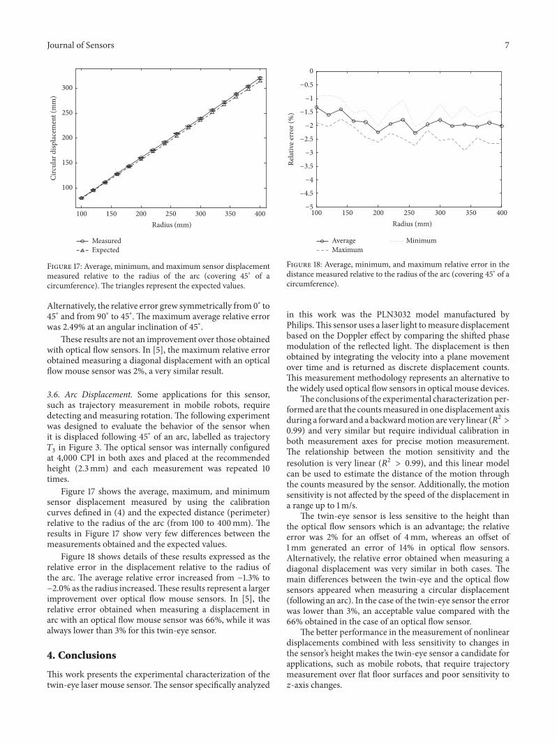
3.6. Arc Displacement. Some applications for this sensor,such as trajectory measurement in mobile robots, requiredetecting and measuring rotation. The following experimentwas designed to evaluate the behavior of the sensor whenit is displaced following 45∘ of an arc, labelled as trajectory𝑇3in Figure 3. The optical sensor was internally configured
at 4,000 CPI in both axes and placed at the recommendedheight (2.3mm) and each measurement was repeated 10times.
Figure 17 shows the average, maximum, and minimumsensor displacement measured by using the calibrationcurves defined in (4) and the expected distance (perimeter)relative to the radius of the arc (from 100 to 400mm). Theresults in Figure 17 show very few differences between themeasurements obtained and the expected values.
Figure 18 shows details of these results expressed as therelative error in the displacement relative to the radius ofthe arc. The average relative error increased from −1.3% to−2.0% as the radius increased.These results represent a largerimprovement over optical flow mouse sensors. In [5], therelative error obtained when measuring a displacement inarc with an optical flow mouse sensor was 66%, while it wasalways lower than 3% for this twin-eye sensor.
4. Conclusions
This work presents the experimental characterization of thetwin-eye laser mouse sensor.The sensor specifically analyzed
100 150 200 250 300 350 400
0
Radius (mm)
Rela
tive e
rror
(%)
−0.5
−1
−1.5
−2
−2.5
−3
−3.5
−4
−4.5
−5
AverageMaximum
Minimum
Figure 18: Average, minimum, and maximum relative error in thedistance measured relative to the radius of the arc (covering 45∘ of acircumference).
in this work was the PLN3032 model manufactured byPhilips.This sensor uses a laser light tomeasure displacementbased on the Doppler effect by comparing the shifted phasemodulation of the reflected light. The displacement is thenobtained by integrating the velocity into a plane movementover time and is returned as discrete displacement counts.This measurement methodology represents an alternative tothe widely used optical flow sensors in optical mouse devices.
The conclusions of the experimental characterization per-formed are that the countsmeasured in one displacement axisduring a forward and a backwardmotion are very linear (𝑅2 >0.99) and very similar but require individual calibration inboth measurement axes for precise motion measurement.The relationship between the motion sensitivity and theresolution is very linear (𝑅2 > 0.99), and this linear modelcan be used to estimate the distance of the motion throughthe counts measured by the sensor. Additionally, the motionsensitivity is not affected by the speed of the displacement ina range up to 1m/s.
The twin-eye sensor is less sensitive to the height thanthe optical flow sensors which is an advantage; the relativeerror was 2% for an offset of 4mm, whereas an offset of1mm generated an error of 14% in optical flow sensors.Alternatively, the relative error obtained when measuring adiagonal displacement was very similar in both cases. Themain differences between the twin-eye and the optical flowsensors appeared when measuring a circular displacement(following an arc). In the case of the twin-eye sensor the errorwas lower than 3%, an acceptable value compared with the66% obtained in the case of an optical flow sensor.
The better performance in the measurement of nonlineardisplacements combined with less sensitivity to changes inthe sensor’s height makes the twin-eye sensor a candidate forapplications, such as mobile robots, that require trajectorymeasurement over flat floor surfaces and poor sensitivity to𝑧-axis changes.

8 Journal of Sensors
Competing Interests
The authors declare no competing interests regarding thepublication of this paper.
Acknowledgments
The authors acknowledge the support of the Governmentof Catalonia (Comissionat per a Universitats i Recerca,Departament d’Innovacio, Universitats i Empresa) and theEuropean Social Fund.
References
[1] Agilent Technologies, “Optical mice and how they work,”WhitePaper 5988-4554EN, 2001.
[2] Optical navigation using one-dimensional correlation, Patent:US7315013, January 2008.
[3] T. W. Ng, “The optical mouse as a two-dimensional displace-ment sensor,” Sensors and Actuators, A: Physical, vol. 107, no. 1,pp. 21–25, 2003.
[4] U. Minoni and A. Signorini, “Low-cost optical motion sensors:an experimental characterization,” Sensors and Actuators A:Physical, vol. 128, no. 2, pp. 402–408, 2006.
[5] J. Palacin, I. Valganon, and R. Pernia, “The optical mousefor indoor mobile robot odometry measurement,” Sensors andActuators A: Physical, vol. 126, no. 1, pp. 141–147, 2006.
[6] R. J. Moore, G. J. Taylor, A. C. Paulk, T. Pearson, B. vanSwinderen, and M. V. Srinivasan, “FicTrac: a visual method fortracking spherical motion and generating fictive animal paths,”Journal of Neuroscience Methods, vol. 225, pp. 106–119, 2014.
[7] I. Nagai, K. Watanabe, K. Nagatani, and K. Yoshida, “Non-contact position estimation device with optical sensor andlaser sources for mobile robots traversing slippery terrains,”in Proceedings of the 23rd IEEE/RSJ International Conferenceon Intelligent Robots and Systems (IROS ’10), pp. 3422–3427,October 2010.
[8] J. A. Cooney, W. L. Xu, and G. Bright, “Visual dead-reckoningfor motion control of a Mecanum-wheeled mobile robot,”Mechatronics, vol. 14, no. 6, pp. 623–637, 2004.
[9] N. Tunwattana, A. P. Roskilly, and R. Norman, “Investigationsinto the effects of illumination and acceleration on opticalmouse sensors as contact-free 2D measurement devices,” Sen-sors and Actuators A: Physical, vol. 149, no. 1, pp. 87–92, 2009.
[10] D. Hyun, H. S. Yang, H. R. Park, and H.-S. Park, “Differentialoptical navigation sensor for mobile robots,” Sensors and Actu-ators A: Physical, vol. 156, no. 2, pp. 296–301, 2009.
[11] J.-S. Hu, Y.-J. Chang, and Y.-L. Hsu, “Calibration and on-linedata selection of multiple optical flow sensors for odometryapplications,” Sensors and Actuators A: Physical, vol. 149, no. 1,pp. 74–80, 2009.
[12] D. Martınez, J. Moreno, M. Tresanchez et al., “Measuring gasconcentration and wind intensity in a turbulent wind tunnelwith a mobile robot,” Journal of Sensors, vol. 2016, Article ID7184980, 8 pages, 2016.
[13] C. Shen, Z. Bai, H. Cao et al., “Optical flow sensor/INS/magnetometer integrated navigation system for MAV in GPS-denied environment,” Journal of Sensors, vol. 2016, Article ID6105803, 10 pages, 2016.
[14] S. Hengstler, D. Prashanth, S. Fong, and H. Aghajan, “MeshEye:a hybrid-resolution smart camera mote for applications in
distributed intelligent surveillance,” in Proceedings of the 6thInternational Symposium on Information Processing in SensorNetworks (IPSN ’07), pp. 360–369,Cambridge,Mass,USA,April2007.
[15] M. Tresanchez, T. Palleja, M. Teixido, and J. Palacın, “Usingthe image acquisition capabilities of the optical mouse sensorto build an absolute rotary encoder,” Sensors and Actuators A:Physical, vol. 157, no. 1, pp. 161–167, 2010.
[16] M. Tresanchez, T. Palleja, M. Teixido, and J. Palacın, “Using theoptical mouse sensor as a two-Euro counterfeit coin detector,”Sensors, vol. 9, no. 9, pp. 7083–7096, 2009.
[17] M. Tresanchez, T. Palleja,M. Teixido, and J. Palacın, “Measuringyarn diameter using inexpensive optical sensors,” in Proceedingsof the Procedia Engineering, Eurosensor XXIV Conference, vol. 5,pp. 236–239, Linz, Austria, September 2010.
[18] N. N. A. Charniya and S. V. Dudul, “Simple low-cost systemfor thickness measurement of metallic plates using laser mousenavigation sensor,” IEEE Transactions on Instrumentation andMeasurement, vol. 59, no. 10, pp. 2700–2705, 2010.
[19] M. M. da Silva, J. R. D. A. Nozela, M. J. Chaves, R. Alves BragaJunior, and H. J. Rabal, “Optical mouse acting as biospecklesensor,” Optics Communications, vol. 284, no. 7, pp. 1798–1802,2011.
[20] P. Pande, G. L. Monroy, R. M. Nolan, R. L. Shelton, and S. A.Boppart, “Sensor-based technique for manually scanned hand-held optical coherence tomography imaging,” Journal of Sensors,vol. 2016, Article ID 8154809, 7 pages, 2016.
[21] M. Liess, G. Weijers, C. Heinks et al., “A miniaturized multidi-rectional optical motion sensor and input device based on laserself-mixing,” Measurement Science and Technology, vol. 13, no.12, pp. 2001–2006, 2002.
[22] Philips, “Philips laser sensors-technology white paper,” Doc-ument PLS-RGU-05-1061, Philips, Amsterdam, Netherlands,2005.
[23] Philips Laser Sensors, Philips Laser Doppler technology, 2011,http://www.photonics.philips.com/.
[24] A. Pruijmboom, S. Booij, M. Schemmann et al., “A VCSEL-based miniature laser-self-mixing interferometer with inte-grated optical and electronic components,” in Proceedings ofthe Photonics Packaging Integration and Interconnects IX, vol.7221 of Proceedings of the SPIE, p. 72210S, San Jose, Calif, USA,January 2009.
[25] A. Pruijmboom, M. Schemmann, J. Hellmig, J. Schutte,H. Moench, and J. Pankert, “VCSEL-based miniature laser-Doppler interferometer,” inProceedings of the SPIE InternationalSociety for Optical Engineering, Vertical-Cavity Surface-EmittingLasers XII, vol. 6908, pp. 690801–690807, 2008.
[26] S. Shinohara, A. Mochizuki, H. Yoshida, and M. Sumi, “Laserdoppler velocimeter using the self-mixing effect of a semicon-ductor laser diode,” Applied Optics, vol. 25, no. 9, pp. 1417–1419,1986.
[27] G. Giuliani, M. Norgia, S. Donati, and T. Bosch, “Laser diodeself-mixing technique for sensing applications,” Journal ofOptics A: Pure and Applied Optics, vol. 4, no. 6, pp. S283–S294,2002.
[28] Philips Laser Sensors, Twin-Eye laser sensors, 2016, http://www.photonics.philips.com/.

International Journal of
AerospaceEngineeringHindawi Publishing Corporationhttp://www.hindawi.com Volume 2014
RoboticsJournal of
Hindawi Publishing Corporationhttp://www.hindawi.com Volume 2014
Hindawi Publishing Corporationhttp://www.hindawi.com Volume 2014
Active and Passive Electronic Components
Control Scienceand Engineering
Journal of
Hindawi Publishing Corporationhttp://www.hindawi.com Volume 2014
International Journal of
RotatingMachinery
Hindawi Publishing Corporationhttp://www.hindawi.com Volume 2014
Hindawi Publishing Corporation http://www.hindawi.com
Journal ofEngineeringVolume 2014
Submit your manuscripts athttp://www.hindawi.com
VLSI Design
Hindawi Publishing Corporationhttp://www.hindawi.com Volume 2014
Hindawi Publishing Corporationhttp://www.hindawi.com Volume 2014
Shock and Vibration
Hindawi Publishing Corporationhttp://www.hindawi.com Volume 2014
Civil EngineeringAdvances in
Acoustics and VibrationAdvances in
Hindawi Publishing Corporationhttp://www.hindawi.com Volume 2014
Hindawi Publishing Corporationhttp://www.hindawi.com Volume 2014
Electrical and Computer Engineering
Journal of
Advances inOptoElectronics
Hindawi Publishing Corporation http://www.hindawi.com
Volume 2014
The Scientific World JournalHindawi Publishing Corporation http://www.hindawi.com Volume 2014
SensorsJournal of
Hindawi Publishing Corporationhttp://www.hindawi.com Volume 2014
Modelling & Simulation in EngineeringHindawi Publishing Corporation http://www.hindawi.com Volume 2014
Hindawi Publishing Corporationhttp://www.hindawi.com Volume 2014
Chemical EngineeringInternational Journal of Antennas and
Propagation
International Journal of
Hindawi Publishing Corporationhttp://www.hindawi.com Volume 2014
Hindawi Publishing Corporationhttp://www.hindawi.com Volume 2014
Navigation and Observation
International Journal of
Hindawi Publishing Corporationhttp://www.hindawi.com Volume 2014
DistributedSensor Networks
International Journal of