Embed Size (px)
Citation preview
Research ArticleEmuStack: An OpenStack-Based DTN Network EmulationPlatform (Extended Version)
Haifeng Li, Huachun Zhou, Hongke Zhang, Bohao Feng, and Wenfeng Shi
School of Electronic and Information Engineering, Beijing Jiaotong University, Beijing 100044, China
Correspondence should be addressed to Haifeng Li; [email protected]
Received 21 August 2016; Accepted 25 October 2016
Academic Editor: Xiaohong Jiang
Copyright © 2016 Haifeng Li et al. This is an open access article distributed under the Creative Commons Attribution License,which permits unrestricted use, distribution, and reproduction in any medium, provided the original work is properly cited.
With the advancement of computing and network virtualization technology, the networking research community showsgreat interest in network emulation. Compared with network simulation, network emulation can provide more relevant andcomprehensive details. In this paper, EmuStack, a large-scale real-time emulation platform for Delay Tolerant Network (DTN),is proposed. EmuStack aims at empowering network emulation to become as simple as network simulation. Based on OpenStack,distributed synchronous emulation modules are developed to enable EmuStack to implement synchronous and dynamic, precise,and real-time network emulation. Meanwhile, the lightweight approach of using Docker container technology and networknamespaces allows EmuStack to support a (up to hundreds of nodes) large-scale topology with only several physical nodes. Inaddition, EmuStack integrates the Linux Traffic Control (TC) tools with OpenStack for managing and emulating the virtual linkcharacteristics which include variable bandwidth, delay, loss, jitter, reordering, and duplication. Finally, experiences with our initialimplementation suggest the ability to run and debug experimental network protocol in real time. EmuStack environment wouldbring qualitative change in network research works.
1. Introduction
Thecurrent Internet is based on a number of key assumptionson communication system, including a long-term and stableend-to-end path, small packet loss probability, and shortround-trip time. However, many challenging networks (suchas sensor/actuator networks and ad hoc networks) cannotsatisfy one or more of those assumptions. Excited enough,there have been increasing efforts to support these challeng-ing networks on some special delay and interrupt scenes [1, 2].In particular, in order to adapt Internet to these challengingenvironments, Fall proposes Delay Tolerant Networks (DTN)[3]. The key idea of DTN is custody transfer [4] whichadopts the hop-by-hop reliable delivery to guarantee the end-to-end reliability. DTN was initially invented for the deepspace communication, while currently it has been graduallyapplied in wireless sensor networks, ad hoc networks, andeven satellite networks.
In DTN areas, related research works such as routing andcongestion control strategies have obtained many achieve-ments [5, 6] along with a number of DTN implementations
such as DTN2, ION, and IBRDTN [7–9]. However, manyproblems [10, 11] such as security and contact plan designhave not been resolved yet.
In order to further study DTN architecture, many exper-imental platforms have been designed. Koutsogiannis imple-ments a testbed to evaluate space-suitable DTN architec-tures and protocols with many deep space communicationscenarios [12]. The DTN testbed can support about tennodes experimental topology. Based on the generic-purposewireless network bench, Beuran designs a testbed namedQOMB [13]. QOMB has a good support for emulating alarge-scale mobile networks, but it wastes lots of hardwareresources since none of virtual computing technology isemployed. Thus, QOMB lacks a monitoring system; theexperimental fidelity cannot be guaranteed especially in thelarge-scale scene. Komnios introduces the SPICE testbed [14]for researching space and satellite communication. SPICE isequipped with special hardware and it can accurately emu-late the link characteristics between the space and groundstations. However, due to the introduction of professionalhardware, SPICE is hard to be imitated by other researchers.
Hindawi Publishing CorporationMobile Information SystemsVolume 2016, Article ID 6540207, 15 pageshttp://dx.doi.org/10.1155/2016/6540207
2 Mobile Information Systems
Meanwhile, without using network virtualization technology,the emulation topology of SPICE is fixed and will be changeddifficultly.
With the advancement of network and compute vir-tualization technology, it becomes much easier to designand implement a scalable and flexible emulation platformthan before. In this work, EmuStack, a network emulationplatform for DTN, is introduced. Our design objective isenabling EmuStack to support a large-scale, real-time, anddistributed network emulation and provide synchronousand dynamical precise management for topology and linkcharacteristics. For example, Docker container technology[15] is utilized as the compute virtualization technique intoefficiently virtualize several physical emulation nodes intohundreds of virtual emulation nodes. By integrating LinuxTraffic Control (TC) utility [16] with OpenStack [17], EmuS-tack can achieve more fine-grained control of the virtualtopology and link characteristics. Meanwhile, OpenStack iscomposed of various independent modules; thus it possessesa good support for the development of the other functionali-ties in EmuStack. To improve the performance of EmuStack,many OpenStack subprojects are adopted. An example isCeilometer [18] which is developed lightly and integrated intoEmuStack for ensuring experimental fidelity andmonitoring,alarming, and collecting relevant data.
As we have a deeper insight into our initial work [19],in this paper, we further present details of controlling linkcharacteristics and analyze the reason for link rate-limitingdifference between the Ethernet device of virtual emulationnode and the TAP device of physical emulation node.Moreover, we further introduce EmuStack scalability andperformance and discuss their main factors. Additionally, weprovide one more DTN experiment to better evaluate anddemonstrate the performance of EmuStack.
The remainder of this paper is organized as follows.In Section 2 we introduce the related work. In Sections 3and 4, we present architectural design, implementation ofEmuStack and thoroughly discuss performance of EmuStack.Then we reproduce two published classic DTN experimentsand compare and analyze the key experimental results inSection 5. Finally, in Section 6, we conclude this paper alongwith future works.
2. Related Work
Recently, with the advancement of container virtualiza-tion technology, network researchers show their interest inemploying container to construct their experimental plat-forms to support their large-scale topology experiments.Emulab [20] is one of the well-known testbeds using thecontainer virtualization in Linux. Due to the efficiency ofcontainer, Emulab possesses a good support for scalability.Although these technologies introduced in Emulab are notthe latest now, the design philosophies are still helpful forcurrent researchers to design large-scale test bed. Addition-ally, Lantz et al. [21] designed Mininet based on containervirtualization technique including processes and networknamespaces technique. Mininet can support SDN and runon a single computer. Handigol et al. [22] further improved
Mininet performance with enhancements to resource provi-sioning, isolation, and monitoring system. Besides, Handigolreplicated a number of previously published experimentalresults and proved that Linux Container (LXC) [23] tech-nology is not only lightweight but also possesses a goodfidelity and performance. In order to perform an in-depthperformance evaluation of LXC,Xavier et al. [24] conducted anumber of experiments to evaluate various compute virtuali-zation technologies andfinally proved that LXCvirtualizationhas a near-native performance on CPU, memory, disk, andnetwork. Therefore, in EmuStack, we employ Docker con-tainer (based on LXC) as compute virtualization technology.
OpenStack is an open-source reference frameworkmainly for developing private and public cloud, which con-sists of loosely-coupled components that can control hard-ware pools of compute, network, and storage resources.OpenStack is composed of many different independentmodules, and anyone can add additional components intoOpenStack tomeet their requirements.Therefore, OpenStackis definitely a good choice for developing emulation platform.
3. Architectural Design
This section describes the overall architecture design ofEmuStack from the perspective of hardware and software.
3.1. Hardware. Figure 1 shows EmuStack hardware structure(where gray rectangles stand for primary services installed).EmuStack hardware can be composed of only several physicalnodes (general-purpose computer). There are two types ofphysical nodes: network emulator and physical emulationnodes. Network emulator is the core hardware which is aphysical node equipped with multiple NICs in EmuStack andit plays multiple roles. It is not only an OpenStack controllernode which manages compute and network resources and anOpenStack network node which manages virtual emulationnetworks, but also an emulation orchestratorwhich is respon-sible for creating emulation parameters and orchestrating thewhole resources of CPU, memory, and network. In addition,physical emulation node is a compute node of OpenStack,which hosts all virtual emulation nodes and executes theemulation control commands from network emulator.
In EmuStack, there are two types of physical networks,namely, the management network and emulation network.Management network carries management traffic which con-sists of lightweight control information and usually does notbecome the determinant of performance. Emulation networktransfers emulation data which consumes much bandwidthand would vary greatly with different DTN protocol exper-iments. Therefore, the physical emulation network possiblybecomes the main limitation of EmuStack. For several physi-cal nodes systemof EmuStack, adopting the star structure cansolve the emulation data traffic bottleneck problem, as shownin the bottom right of Figure 1. In this structure, all emulationNICs of physical emulation nodes are directly connected tothose of network emulator. NICs of network emulator areattached to an Open vSwitch bridge, where the “internal”device named after itself is assigned an IP address belongingto the emulation network. In practice, this physical emulation
Mobile Information Systems 3
Management network
Emulation network
Emulation nodes Network emulator Emulation nodes
Switch
MYSQL serverRABBITMQ server
Nova API
Nova conductor
Neutron serverGlance API
Glance registry
Controller node
Emulation node
Network emulator
Emulation physical topology
Network nodeCompute nodeCompute node
Nova-Compute
Compute node
Open vSwitch agent Open vSwitch agent
Compute node Keystone-all
Nova-scheduler
Neutron-l3 agentNeutron-dhcp
Netem agent Netem agent
Nova-Compute Nova-Compute Open vSwitch agent
Netem agent
Nova-ComputeOpen vSwitch agent
Netem agent
· · ·· · ·agent
Neutron-Netemservice
Figure 1: EmuStack hardware structure.
network structure can meet most requirements of our DTNresearch works; however if researchers want to construct theEmuStack system that consists of dozens of physical nodes,this structure would become infeasible since network emu-lator would not have enough NICs to directly connect to allthe emulation NICs of physical emulation nodes. For systemwith dozens of physical nodes, physical emulation networkcan employ several physical switches to carry the emulationdata as management network does. In this scheme, as thefirst step, we need to determine which one of physical NICson network emulator (and physical emulation nodes) willcarry management traffic.Then we connect all the remainingNICs of network emulator (and physical emulation nodes)to those physical switches. Those physical switches portswill need to be specially configured to allow trunked orgeneral traffic. Finally, for EmuStack system with hundredsof physical nodes, as a part of the future work, we willextend network emulator to support distributed processingand enable multiple network emulators to exist in EmuStack.
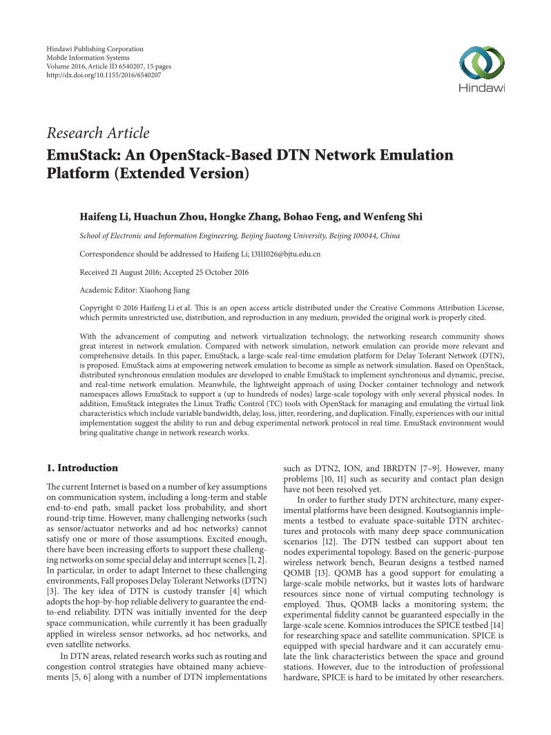
3.2. Software. Figure 2 describes EmuStack software synopsisinvolving network emulator, physical emulation node, andvirtual emulation node. As the key component of EmuStack,network emulator carries many open-source services andcustomized service extensions. Nova service and the coreplugin in Neutron service is attended to initialize virtualemulation nodes and virtual emulation network, respectively.Additionally, these services also have the ability to create,modify, and delete virtual emulation nodes and virtual
emulation network. Neutron-Netem service is responsible forgenerating experimental parameters and data to dynamicallycontrol experimental program, topologies, and link charac-teristics.Meanwhile, in order to provide sufficient fidelity andreduce experimental complexity at the same time, we adoptTelemetry Management (Ceilometer) [18] service to monitorand collect hardware resources and experimental data. Inaddition, Keystone [25], Horizon [26], and Glance [27] areutilized to provide the support for managing authentication,authorization, service catalog, web interface, and imageservices. Besides, as a part of the future work, on the basis ofOpenStack Heat service, we will develop the orchestrator tomore efficiently and flexibly orchestrate the distributed hard-ware resource management [28]. Most of those services areopen-source projects and available in OpenStack; hence weonly need to integrate them to meet most EmuStack designrequirements. In order to implement synchronous, dynamic,precise, and real-time emulation control service, we designand implement the Neutron-Netem service and Neutron-Netem agent, which will be further discussed in Section 4.
As shown in the bottom left of Figure 2, physical emu-lation node is regarded as a compute node in OpenStackwhere virtual emulation nodes are hosted. Physical emulationnode runs Nova-Compute service driven by the Dockerhypervisor to manage virtual emulation nodes and OpenvSwitch agent to execute the managing emulation networkcommands (including create, modify, and delete function)from network emulator. Open vSwitch agent employs twoOpen vSwitch (OVS), “OVS for emulation” and “OVS for

4 Mobile Information Systems
OVS for control
Neutron-Netem service(dynamic topology,link characteristics)
Core plugin(initial topology, QoS
by open vSwitch)
Nova Glance Keystone
Ceilometer NTP
Horizon
Neutron
Orchestrator
Heat
Emulation virtual topologyVEN VEN VEN
Nova-Compute
Neutron-Netem agentOpen vSwitch agent
VEN: virtual emulation node
Network emulator
Docker
Telemetry agent
NTP
Puppet client
Protocol software
NTP
Virtual emulation node
PC
Switch
OVS for emulation
Physical emulation node
VEN VEN
VEN
Management network
Emulation network
Figure 2: Synopsis of EmuStack software.
control” to manage virtual emulation networks and virtualmanagement networks, respectively. Open vSwitch agentsmanage virtual networks by configuring flow rules on theabove two OVS. Moreover, as the agent of Ceilometer servicein network emulator, Telemetry Agent is responsible for pub-lishing collected data to network emulator through the man-agement network and creating alarms once collected databreaks the monitoring rules. Finally, Neutron-Netem agentis designed to precisely and dynamically control emulationtopologies and link characteristics, which will be furtherintroduced in Section 4.
As shown in the upper left of Figure 2, virtual emulationnode (VEN) is a Docker virtual machine which is hosted inphysical emulation node. It is spawned from the operatingsystem image where Network Time Protocol (NTP) service,custom network protocol software, and Puppet client servicecan be installed. In particular, Puppet client service can be uti-lized by virtual emulation nodes to receive control informa-tion from network emulator or physical emulation nodes.
Note that time synchronization is very essential forEmuStack. The DTN bundle protocol depends on absolute
time to determine whether received packets are expired. Fur-thermore, EmuStack must ensure the experimental programin different virtual emulation nodes which can be exactly syn-chronously executed in the correct time sequences.Therefore,Chrony [29], an implementation of NTP [30], is installed inall nodes to provide the properly synchronizing services. Indetail, network emulator is configured to reference accuratetime servers while physical and virtual emulation nodes referto network emulator. In our local area network (LAN) ofEmuStack, the time synchronization precision reaches as highas 0.1 milliseconds, which meets the requirements for mostemulation experiments.
4. Implementation
This section describes the details of EmuStack core modules(Neutron-Netem service and Neutron-Netem agent). Firstly,in order to sketch the outline of EmuStack implement, EmuS-tack emulationworkflow is described in Section 4.1. Secondly,Sections 4.2, 4.3, and 4.4 present the details of emulationsynchronous control, topology control, and customization of
Mobile Information Systems 5
Orchestrator Neutron server Physical emulation nodes
ML2-OVS pluginL2-OVS driver
L2-OVS agent Storage
Storage
serviceNeutron-Netem Neutron-Netem
driver
Network-create requestInitializes topology
Adds rules for interface to
Emulation-data-create request
Network-create response
Creates and storesemulation data
Emulation-data-create response
Emulation-run request
Transmits emulation configurationand data to each physical nodes
Stores configuration and data
Transmits emulation configurationto virtual emulation nodes
Generates absolute timestamp to start emulation
Runs experiment software, controls topology and linkcharacteristics on virtual
emulation nodesEmulation loop,
absolute time controlEmulation-run(finish) response
GUI/CLI
br-int and br-tun/br-ethx
←M
ESSA
GE
RPC→
←M
ESSA
GE
RPC→
←RE
STFU
L A
PI→
Neutron-Netem agent
Figure 3: Process flow of emulation network.
link characteristics, respectively. Finally, the scalability andperformance of EmuStack are discussed in Section 4.5.
4.1. EmulationWorkflow. Before the beginning of emulation,we first create a virtual machine image, where specialsoftware and shell scripts should be installed to fulfill thespecific experimental requirements. For example, you mustinstall an SSH server (or Puppet client) into the image andensure that it starts up on boot with the correct configuration,or you may install shell scripts to collect some experimentresults. Next, we create virtual networks before launchingvirtual emulation nodes. Virtual networks are composed oftwo types of networks, namely, management network andemulation network. Management network is Neutron flatnetwork in OpenStack, where all nodes (including virtual,physical emulation nodes, and network emulator) reside onthe same network and no VLAN tags are created. Emulationnetwork involves one or more private virtual networks.Moreover, one virtual emulation node could belong to eitherone or more virtual emulation networks. After creating
virtual network, we launch a sufficient number of virtualemulation nodes and initialize virtual networks, right beforerunning the emulation.
Unlike a simulator running in virtual time based ondiscrete event, EmuStack runs in real time and cannot pausea node’s clock to pend for events. For a distributed real-timeemulation platform, it is difficult to ensure that every controlcommand can be executed synchronously in the differentphysical nodes due to the stochastic communication delayand background system load. In order to avoid communi-cation delay, especially the control information transmissiondelay, EmuStack stores the control information in the local-storage before emulation starts to run.
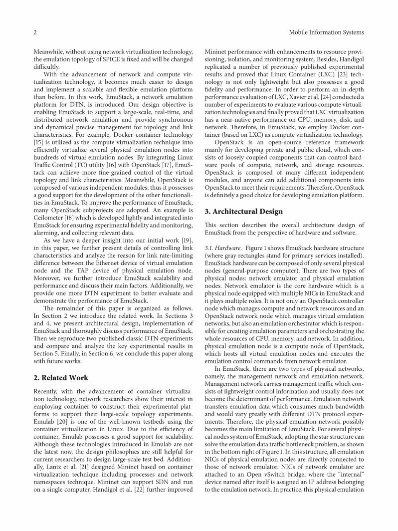
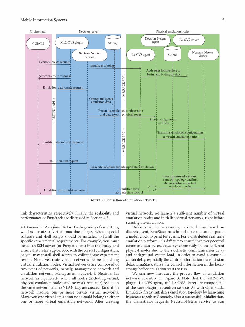
We can now introduce the process flow of emulationnetwork described in Figure 3. Note that the ML2-OVSplugin, L2-OVS agent, and L2-OVS driver are componentsof the core plugin in Neutron service. As with OpenStack,EmuStack firstly initializes emulation topology by launchinginstances together. Secondly, after a successful initialization,the orchestrator requests Neutron-Netem service to run

6 Mobile Information Systems
mobility module to create topology and link characteristicsdata. Meanwhile, in order to support the requirements ofthose who evaluate the same experimental protocol withdifferent protocol parameters and the same model data,Neutron-Netem service stores the generated model data inthe persistent storage. Thirdly, Neutron-Netem service dis-patches the emulation data to each agent residing in everyphysical emulation node. The emulation data is split into dif-ferent parts for each agent and every agent just only receivesits own part and stores it. Relatively, every agent can trans-mit experimental configuring parameters to virtual emula-tion nodes by invoking Puppet server API. In each virtualemulation node, Puppet client works in kick-mode and startsto receive configuration (or command) once triggered byNeutron-Netem agent. Finally, after dispatching the emula-tion data, the orchestrator sends a request to Neutron-Netemservice to start emulation; then Neutron-Netem servicedelivers an absolute timestamp to every agent. Once thestaring time is up, agents will start to emulate the experiment,and therefore, the starting timestamp has to be a little (such assixty seconds) larger than current timestamp, and that extratime is left for Neutron-Netem agents receiving the startingtimestamp.
In EmuStack, Neutron-Netem service is organized intoseparate submodules such as storage and mobility modules.In particular, Neutron-Netem service provides a simple plu-gin mechanism to enable users to extend different mobilitymodules. Thus mobility modules can be individually built asresearchers’ own experimental purposes. The various mobil-ity modules are intended to provide required realistic net-work emulation environment for different experimental net-work protocol development. Besides, Neutron-Netem serviceprovides the inheritance mechanism that a mobility modulecan be developed based on the others. The primary func-tionality of amobilitymodule is to create data for dynamicallycontrolling emulation topology and link characteristics. InSection 5, we will employ two mobility modules for DTNlarge file transmission experiment and the DTN routingprotocol comparison experiment of Probabilistic Routingwith Epidemic, respectively.
4.2. Synchronous Control. Algorithm 1 describes the syn-chronous control of Neutron-Netem agent. As shown inlines (2) to (4), Neutron-Netem agents all are asleep andsynchronously start emulation once the starting time comes.The time synchronization accuracy depends on the sleepingtime SLEEP TIME and the NTP synchronization precision.Since the NTP synchronization precision is as high as 0.1milliseconds in our platform environment, the synchro-nization accuracy is only up to SLEEP TIME. In fact, theSLEEP TIME is a trade-off between synchronization preci-sion and system load. In practice, we set SLEEP TIME to 100(milliseconds) to satisfy the requirements ofmost experimentwith lightweight CPU load.
With the coming of starting time, Algorithm 1 goes intothe outer loop as shown in lines (11) to (23). This outer looptakes advantage of absolute time to control its cycles. Asshown in line (13), LOOP CYCLE (loop cycle) is an import-ant parameter for this loop system. The topology and link
(1) INIT protocol software(2) WHILE current time < starting time(3) sleep SLEEP TIME miliseconds(4) ENDWHILE(5)(6) INIT topology control(7) INIT link characteristics control(8) START state collection(9)(10) SET counter to 0(11) WHILE counter < CONTROL PERIOD(12) increment counter(13) next time = start time + \
LOOP CYCLE ∗ counter(14) control topology(15) control link characteristics(16) control protocol software(17) IF current time – next time > THRESHOLD(18) collect error log(19) END IF(20) WHILE current time < next time(21) sleep SLEEP TIME miliseconds(22) ENDWHILE(23) ENDWHILE(22) KILL all experiment processes
Algorithm 1: Synchronous control on Neutron-Netem agent.
characteristics are updated every LOOP CYCLE.The controloperation delay (lines (14) to (16)) plus sleeping time (lines(20) to (22)) is around equal to LOOP CYCLE. However,due to system load and other unknown factors, the controloperation delay may be larger than LOOP CYCLE by acci-dent; this will lead to synchronous control failure. To helpusers evaluate the fidelity of the experiments, this failureinformation all is logged (lines (17) to (19)). Besides, theexceeded time will force future cycles of the loop to reducethe sleeping time; this will enable platform to synchronizeagain. After the end of outer loop, Neutron-Netem agents killall experiment processes to get ready for next experiment.
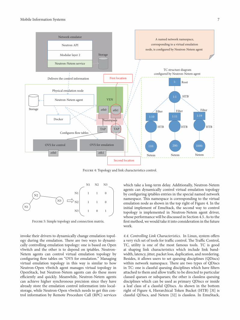
4.3. Controlling Topology. Figure 4 provides details on thecontrolling topology and link characteristics. As shown in theright of Figure 4, Neutron-Netem service delivers the controlinformation toNeutron-Netem agents in advance. Accordingto the received control information, Neutron-Netem agentsinvoke their driver to dynamically control the emulationexperiment once the starting time is coming. In particular,as a part of this control information, the topology controlinformation is described by connection matrix in EmuStack,as shown in Figure 5. In fact, a network topology, no matterhow complex it is, can be represented by a connectingrelationship between any two nodes. An example for a threenodes topology is shown in Figure 5, where “1” corresponds toconnection between two nodes and “0”means disconnection.
In EmuStack, the connection matrix along with timesequences is generated by mobility module. Accordingto connection matrix, Neutron-Netem agents periodically
Mobile Information Systems 7
OVS for control OVS for emulation
VEN
eth0 eth1
TAP TAP
Physical emulation node
eth0 eth1
1:
1:1
1:10 1:11 1:19
HTB HTB HTB
Netem Netem Netem
HTB
Root
Neutron-Netem agent
Filter Filter Filter
TC structure diagram configured by Neutron-Netem agent
A named network namespace,corresponding to a virtual emulation
node, is configured by Neutron-Netem agent
Configures flow tables
110: 200: 1000:
Namespace
Neutron API
Modular layer 2
Network emulator
Delivers the control information
Storage
Docker
First location
Second location
Storage
Neutron-Netem service
Figure 4: Topology and link characteristics control.
N1
N2N3
N1 N2 N3
N1
N2
N3
1
1
1
1
1
0
0
0
1
Figure 5: Simple topology and connection matrix.
invoke their drivers to dynamically change emulation topol-ogy during the emulation. There are two ways to dynami-cally controlling emulation topology: one is based on OpenvSwitch and the other is to depend on iptables. Neutron-Netem agents can control virtual emulation topology byconfiguring flow tables on “OVS for emulation.” Managingvirtual emulation topology in this way is similar to howNeutron-Open vSwitch agent manages virtual topology inOpenStack, but Neutron-Netem agents can do these moreefficiently and quickly. Meanwhile, Neutron-Netem agentscan achieve higher synchronous precision since they havealready store the emulation control information into local-storage, while Neutron-Open vSwitch needs to get this con-trol information by Remote Procedure Call (RPC) services
which take a long-term delay. Additionally, Neutron-Netemagents can dynamically control virtual emulation topologyby configuring iptables entries in the special named networknamespace. This namespace is corresponding to the virtualemulation node as shown in the top right of Figure 4. In theinitial implement of EmuStack, the second way to controltopology is implemented in Neutron-Netem agent driver,whose performance will be discussed in Section 4.5. As to thefirst method, we would take it into consideration in the futurework.
4.4. Controlling Link Characteristics. In Linux, system offersa very rich set of tools for traffic control. The Traffic Control,TC, utility is one of the most famous tools. TC is goodat shaping link characteristics which include link band-width, latency, jitter, packet loss, duplication, and reordering.Besides, it allows users to set queuing disciplines (QDiscs)within network namespace. There are two types of QDiscsin TC: one is classful queuing disciplines which have filtersattached to them and allow traffic to be directed to particularclassed queues or subqueues; the other is classless queuingdisciplines which can be used as primary QDiscs or insidea leaf class of a classful QDiscs. As shown in the bottomright of Figure 4, Hierarchical Token Bucket (HTB) [31] isclassful QDiscs, and Netem [32] is classless. In EmuStack,

8 Mobile Information Systems
TC
NIC driver
dev_queue_xmit
hard_start_xmit
Netfilter(iptables)
Socket buffer
Buffer
Socket API
Traffic control
User space
Kernel space
Overflow
Forward
X Y
Y
Switch BHost A
}
Sending program in host A
X
Details of sending program
Simple physical topology
×
Send(buffer)
bzero(buffer, MAXSIZE);while ( fread(buffer) >0 ) {
send(buffer);bzero(buffer, MAXSIZE);
FeedbackFeedback
Figure 6: Rate-limiting difference between two locations.
Neutron-Netem agents use HTB to control link rate, attach-ing filters to HTB QDiscs to distinguish different virtualemulation links. Meanwhile, Netem is used inside HTBleaf classes to emulate variable delay, loss, reordering, andduplication.
In telecommunications, a link is a communication chan-nel that connects two communicating devices (such asnetwork interfaces); a media access control address (MACaddress) is a unique identifier assigned to network interfacefor communications. Hence, in EmuStack, we can use source-destination MAC addresses to configure filter rules to dis-tinguish different virtual emulation links. In particular, dueto the high link asymmetry in most DTN experiments,EmuStack adopts the source-destination ordered pairs to dis-tinguish the difference between uplink and downlink. Mean-while, we elaborately design control policies since TCQDiscsare only good at shaping outgoing traffic. For example, assum-ing a link between node A and node B, for A, EmuStackhandles A’s uplink at one end of the link (on A) and con-trols A’s downlink at the other end of the link (on B); thenemulation data can be shaped bilaterally. In addition, EmuS-tack also can create one or more special intermediate vir-tual nodes for all virtual emulation nodes of the same physicalemulation node to shape their downlink traffic.
We can limit link rate at both locations as shown atthe middle of Figure 4. The two locations marked with redcircles stand for two different network devices. The firstlocation stands for network interfaces in virtual emulationnodes. All network interfaces are corresponding to those ofnamed network namespaces. The second location representsTAP devices which are paired with those network interfacesmentioned above and attached to Open vSwitch (“OVS foremulation”). Limiting link rate at both locations is feasible,but there are some notable differences. Assuming experi-mental network protocols (such as UDP) do not have anycongestion control algorithms, then any rate-limiting atthe second location will lead to a large number of packetloss, but this will not happen at the first location. In mostDTN experiments, rate-limiting leading to much packet lossprobably is not what we want, and wemostly expect that rate-limiting and packet loss do not interfere with each other.
Figure 6 describes the rate-limiting difference betweenthe two locations with a simple topology and a sending pro-gram. In this simple topology,𝑋 device is at the first locationand 𝑌 device is at the second location. Assume that thesending program calls UDP socket API. When sending pro-gram sends application data, Linux kernel copies applicationdata from user space buffer to socket buffer. If socket buffer

Mobile Information Systems 9
Zoom to rectangle
Limited link rate
Pack
et lo
ss ra
te (%
)
1kbps10kbps100 kbps
1Mbps10Mbps
90
80
70
60
50
40
30
20
10
0
Sending rate (times of limiting rate)9876543210
Figure 7: Feature of rate-limiting at the second location.
ever gets full, the blocking socket will put the programin sleep state until the socket buffer has enough space, orthe nonblocking socket will return the error “OperationWould Block” immediately.Therefore, nomatter whichmode(blocking or nonblocking) the socket works in, sendingprogram always receives a “feedback,” and this prevents thesocket buffer from overflowing as shown in Figure 6. Thesepackets are delivered to QDiscs buffer to shape them andfinally transmitted to link by NIC driver. In brief, TC QDiscsconsume packets in socket buffer and clear socket buffer, andthen sending program can send application data to socketbuffer again.As a result, TC indirectly affects the transmissionof sending program; a sufficient TC buffer and the feedbackmechanism ensure packet loss does not to happen. As to rate-limiting at𝑌 (the second location), since there is not feedbackbetween 𝑌 and sending program, 𝑌 ingress buffer willoverflow anddropmost application data as shown in Figure 7.
Figure 7 presents the relationship between packet loss rateand sending rate for rate-limiting at the second location. Asexpected, when rate-limiting is fixed, the larger the sendingrate (times), the more packets the link drops. Meanwhile,setting the sending rate as constant and HTB buffer asdefault, the larger the rate-limiting, the smaller the packetloss rate. For most DTN scenarios, this is not what we wantto see except for testing congestion control algorithms. Forexample, assuming NIC bandwidth is 90Mbps and rate-limiting is 10Mbps, packet loss rate will be up to 80 percent.
In current EmuStack version, we implement all linkcharacteristics control at the first location but only achieverate-limiting function at the second location by configuringingress policing rules in Open vSwitch (OVS for emulation).Although rate-limiting at the second location has been imple-mented in QoS (Quality of Service) plugin of OpenStackNeutron service, it is implemented in centralized model andthe synchronous precision is too low. Hence we reimplement
the function with the distributed model and obtain thathigher synchronous precision is achieved.
4.5. Scalability and Performance. We deploy EmuStack inour experimental platform consisting of nine physical nodes.Each physical node is an identical Dell� PowerEdge� R7202U rack server with one 2.4GHz Intel Xeon E5-2609 pro-cessor (with 4 cores), 10M of L3 cache per core, 32GBRAM, and Broadcom 5720 Quad Port 1 GbE BASE-T. Inparticular, network emulator is integrated with four moreIntel EXPI9402PTDual Port NICs. All management networkinterfaces of nine physical nodes are interconnected by TP-LINK TL-SF1024D Ethernet switch. All emulation networkinterfaces of eight physical emulation nodes are linked tothose of network emulator. The Ubuntu 14.04 LTS Linuxdistribution is installed on the all physical nodes and theNetworkManager service is not allowed to start up upon boot,since NetworkManager always repeatedly invokes the uselessdhclient program and occupies an amazing number of CPUresources whenever EmuStack launches Docker containers.In addition, operating system kernel version is 3.19.0-31, ipta-bles version is 1.4.21, iprouter2 version is ss131122, andDockerversion is 1.10.1. Based on these platform environments, weanalyze the emulation scalability and performance as fol-lows.
Compute (CPU), memory (RAM), and network (NIC)are the three chief factors of EmuStack scalability. To makeefficient use of CPU and RAM, EmuStack adopts Dockercontainer as virtualization technology instead of kernel-based full virtualization solutions. Docker containers sharethe same operating system kernel so that they can consumefewer CPU and RAM resources. For example, our platformlaunches sixty containers on a single machine with aboutnine percent of CPU usage and ten percent of RAM usage,which serve as virtual emulation nodes which are installedwithUbuntu 14.04 LTS and start upwithOpenSSH server andPuppet client. Additionally, in order to ensure that emulationnetwork does not hit network bottleneck easily, EmuStackdispatches compute requests to as few as possible physicalemulation nodes for the same experiment, so most virtualemulation nodes are interconnected by the internal bridge(OVS for emulation) and communications between them canconsume the least bandwidth of physical emulation network.Meanwhile, all emulation network interfaces on the networkemulator are attached to a Linux bridge to improve thebandwidth of physical emulation network. All of these enableEmuStack to support hundreds of nodes with nine physicalnodes.
The major factor of EmuStack performance is theupdating delay, the time consumed by changing experi-mental emulation topology or link characteristics for onetime. In Algorithm 1, the updating delay determines theLOOP CYCLE parameter presented on line (13). The mini-mum LOOP CYCLE should be no less than the maximumupdating delay; otherwise EmuStack will fails to synchronize.In addition, current EmuStack version employs iptables andTC utility to dynamically control the virtual emulation net-work, respectively. Hence the iptables and TC performancedirectly impact EmuStack performance and their processing
10 Mobile Information Systems
800
2500
700
2000
600
1500
500
1000
400
500
3000
1200
1000
600
800
400
200
02001000
8007006005004003002001000
9000
8000
7000
6000
5000
4000
3000
2000
1000
80706050403020100
403020100
Proc
essin
g de
lay (m
s)Pr
oces
sing
delay
(ms)
Proc
essin
g de
lay (m
s)
1000
600
800
400
200
0
Proc
essin
g de
lay (m
s)
Inserted iptables entries numberon a single network interface
Inserted TC-HTB class numberon a single network interface
Operated virtual nodes numberon a single physical node
Inserted TC-HTB class number = 4
Inserted TC-HTB class number = 15
Inserted TC-HTB class number = 25
0
Operated virtual nodes numberon a single physical node
y = ax2 + bx y = ax + b
y = ax + by = ax + bx
Inserted iptables entries number = 4
Inserted iptables entries number = 20
Inserted iptables entries number = 40
Figure 8: The average performance of iptables and TC.
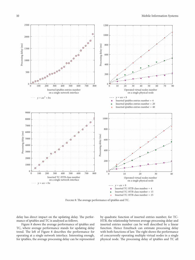
delay has direct impact on the updating delay. The perfor-mance of iptables and TC is analyzed as follows.
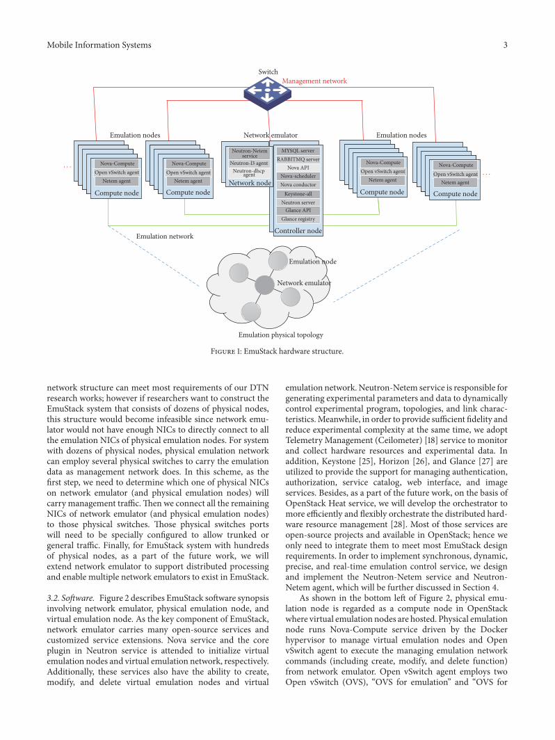
Figure 8 shows the average performance of iptables andTC, where average performance stands for updating delaytrend. The left of Figure 8 describes the performance foroperating at a single network interface. Interesting enough,for iptables, the average processing delay can be represented
by quadratic function of inserted entries number; for TC-HTB, the relationship between average processing delay andinserted entries number can be well described by a linearfunction. Hence EmuStack can estimate processing delaywith both functions of law. The right shows the performanceof concurrently operating multiple virtual nodes in a singlephysical node. The processing delay of iptables and TC all
Mobile Information Systems 11
800 10006004002000
250300350
200150100
500
2000
1500
1000
500
0
Proc
essin
g de
lay (m
s)
Proc
essin
g de
lay (m
s)
40 virtual nodes
30 virtual nodes20 virtual nodes10 virtual nodes
50 virtual nodes60 virtual nodes
800 10006004002000
40 virtual nodes
30 virtual nodes20 virtual nodes10 virtual nodes
50 virtual nodes60 virtual nodes
Number of trials on TC performanceNumber of trials on iptables performance
Figure 9: The real-time performance of iptables and TC.
grow linearly when the inserted iptables entries (or TC-HTBclass) number is fixed, and this is influenced by serialization,contention, and system load.
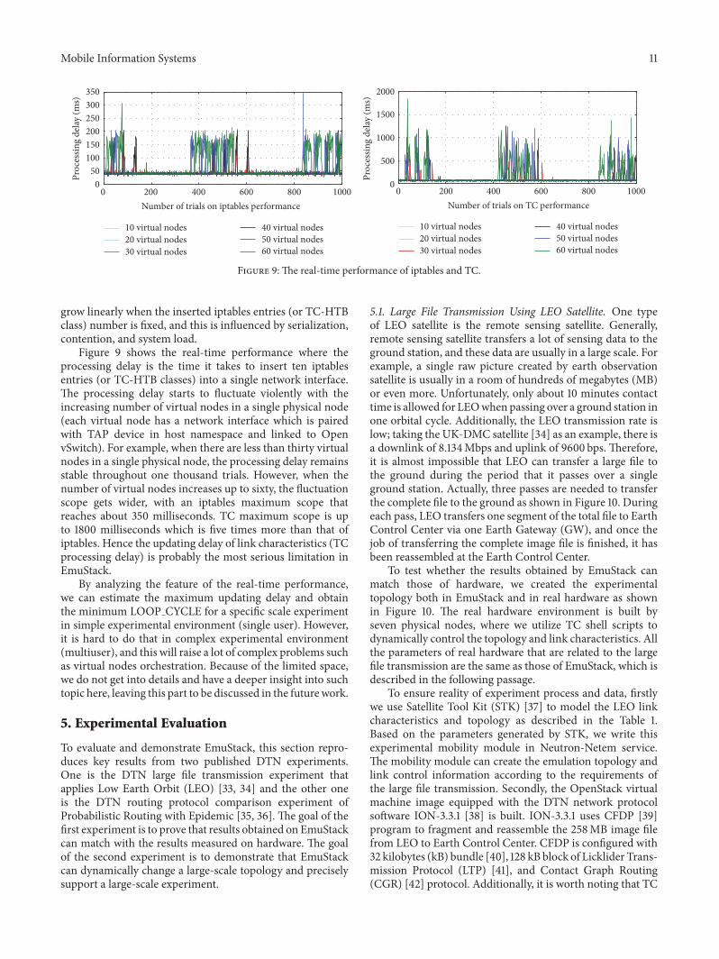
Figure 9 shows the real-time performance where theprocessing delay is the time it takes to insert ten iptablesentries (or TC-HTB classes) into a single network interface.The processing delay starts to fluctuate violently with theincreasing number of virtual nodes in a single physical node(each virtual node has a network interface which is pairedwith TAP device in host namespace and linked to OpenvSwitch). For example, when there are less than thirty virtualnodes in a single physical node, the processing delay remainsstable throughout one thousand trials. However, when thenumber of virtual nodes increases up to sixty, the fluctuationscope gets wider, with an iptables maximum scope thatreaches about 350 milliseconds. TC maximum scope is upto 1800 milliseconds which is five times more than that ofiptables. Hence the updating delay of link characteristics (TCprocessing delay) is probably the most serious limitation inEmuStack.
By analyzing the feature of the real-time performance,we can estimate the maximum updating delay and obtainthe minimum LOOP CYCLE for a specific scale experimentin simple experimental environment (single user). However,it is hard to do that in complex experimental environment(multiuser), and this will raise a lot of complex problems suchas virtual nodes orchestration. Because of the limited space,we do not get into details and have a deeper insight into suchtopic here, leaving this part to be discussed in the futurework.
5. Experimental Evaluation
To evaluate and demonstrate EmuStack, this section repro-duces key results from two published DTN experiments.One is the DTN large file transmission experiment thatapplies Low Earth Orbit (LEO) [33, 34] and the other oneis the DTN routing protocol comparison experiment ofProbabilistic Routing with Epidemic [35, 36]. The goal of thefirst experiment is to prove that results obtained on EmuStackcan match with the results measured on hardware. The goalof the second experiment is to demonstrate that EmuStackcan dynamically change a large-scale topology and preciselysupport a large-scale experiment.
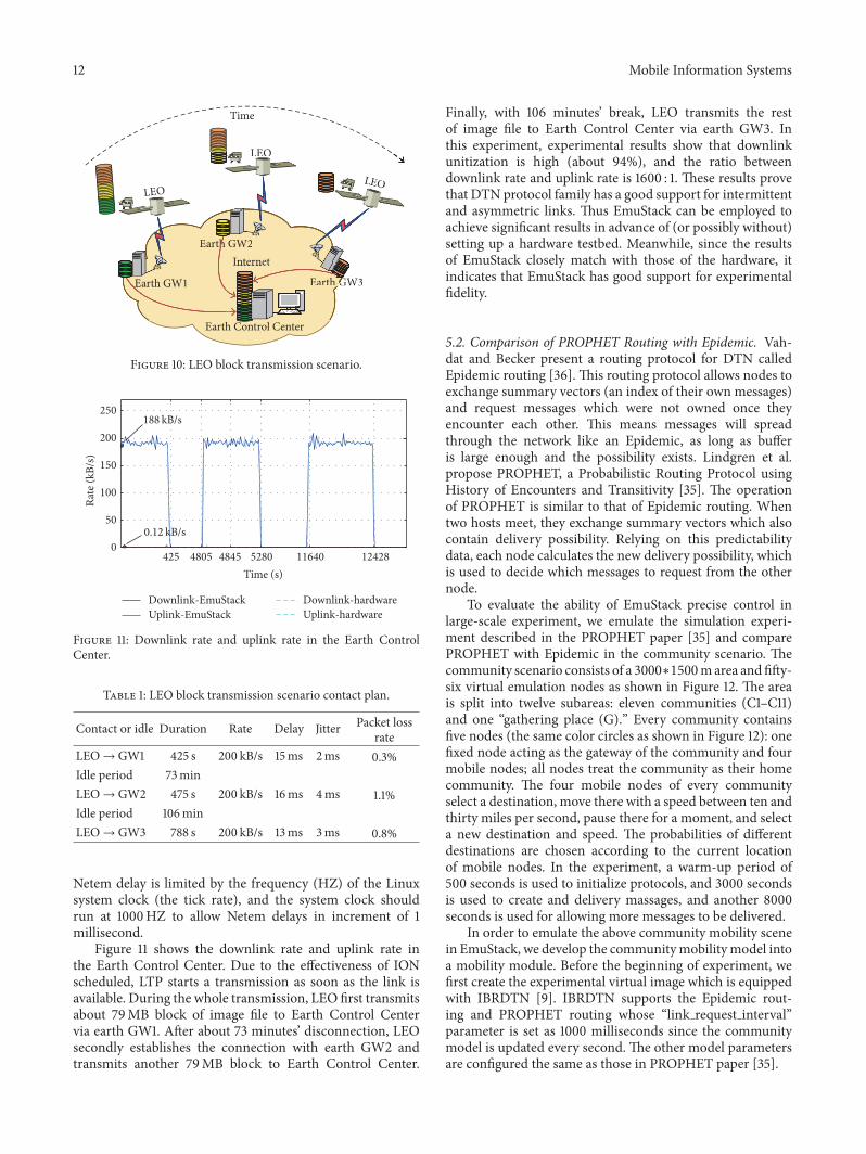
5.1. Large File Transmission Using LEO Satellite. One typeof LEO satellite is the remote sensing satellite. Generally,remote sensing satellite transfers a lot of sensing data to theground station, and these data are usually in a large scale. Forexample, a single raw picture created by earth observationsatellite is usually in a room of hundreds of megabytes (MB)or even more. Unfortunately, only about 10 minutes contacttime is allowed for LEOwhen passing over a ground station inone orbital cycle. Additionally, the LEO transmission rate islow; taking the UK-DMC satellite [34] as an example, there isa downlink of 8.134Mbps and uplink of 9600 bps. Therefore,it is almost impossible that LEO can transfer a large file tothe ground during the period that it passes over a singleground station. Actually, three passes are needed to transferthe complete file to the ground as shown in Figure 10. Duringeach pass, LEO transfers one segment of the total file to EarthControl Center via one Earth Gateway (GW), and once thejob of transferring the complete image file is finished, it hasbeen reassembled at the Earth Control Center.
To test whether the results obtained by EmuStack canmatch those of hardware, we created the experimentaltopology both in EmuStack and in real hardware as shownin Figure 10. The real hardware environment is built byseven physical nodes, where we utilize TC shell scripts todynamically control the topology and link characteristics. Allthe parameters of real hardware that are related to the largefile transmission are the same as those of EmuStack, which isdescribed in the following passage.
To ensure reality of experiment process and data, firstlywe use Satellite Tool Kit (STK) [37] to model the LEO linkcharacteristics and topology as described in the Table 1.Based on the parameters generated by STK, we write thisexperimental mobility module in Neutron-Netem service.The mobility module can create the emulation topology andlink control information according to the requirements ofthe large file transmission. Secondly, the OpenStack virtualmachine image equipped with the DTN network protocolsoftware ION-3.3.1 [38] is built. ION-3.3.1 uses CFDP [39]program to fragment and reassemble the 258MB image filefrom LEO to Earth Control Center. CFDP is configured with32 kilobytes (kB) bundle [40], 128 kB block of Licklider Trans-mission Protocol (LTP) [41], and Contact Graph Routing(CGR) [42] protocol. Additionally, it is worth noting that TC
12 Mobile Information Systems
Earth GW1 Earth GW3
Earth GW2
Earth Control Center
Internet
LEO
LEOLEO
Time
Earth GW1 GW3Earth GG
Earth GW2Internet
LEO
LEOLEO
Figure 10: LEO block transmission scenario.
250
200
150
100
50
0425 48454805 5280 11640 12428
Time (s)
Rate
(kB/
s)
188 kB/s
0.12 kB/s
Downlink-EmuStackUplink-EmuStack
Downlink-hardwareUplink-hardware
Figure 11: Downlink rate and uplink rate in the Earth ControlCenter.
Table 1: LEO block transmission scenario contact plan.
Contact or idle Duration Rate Delay Jitter Packet lossrate
LEO→ GW1 425 s 200 kB/s 15ms 2ms 0.3%Idle period 73minLEO→ GW2 475 s 200 kB/s 16ms 4ms 1.1%Idle period 106minLEO→ GW3 788 s 200 kB/s 13ms 3ms 0.8%
Netem delay is limited by the frequency (HZ) of the Linuxsystem clock (the tick rate), and the system clock shouldrun at 1000HZ to allow Netem delays in increment of 1millisecond.
Figure 11 shows the downlink rate and uplink rate inthe Earth Control Center. Due to the effectiveness of IONscheduled, LTP starts a transmission as soon as the link isavailable. During the whole transmission, LEO first transmitsabout 79MB block of image file to Earth Control Centervia earth GW1. After about 73 minutes’ disconnection, LEOsecondly establishes the connection with earth GW2 andtransmits another 79MB block to Earth Control Center.
Finally, with 106 minutes’ break, LEO transmits the restof image file to Earth Control Center via earth GW3. Inthis experiment, experimental results show that downlinkunitization is high (about 94%), and the ratio betweendownlink rate and uplink rate is 1600 : 1. These results provethat DTN protocol family has a good support for intermittentand asymmetric links. Thus EmuStack can be employed toachieve significant results in advance of (or possibly without)setting up a hardware testbed. Meanwhile, since the resultsof EmuStack closely match with those of the hardware, itindicates that EmuStack has good support for experimentalfidelity.
5.2. Comparison of PROPHET Routing with Epidemic. Vah-dat and Becker present a routing protocol for DTN calledEpidemic routing [36]. This routing protocol allows nodes toexchange summary vectors (an index of their own messages)and request messages which were not owned once theyencounter each other. This means messages will spreadthrough the network like an Epidemic, as long as bufferis large enough and the possibility exists. Lindgren et al.propose PROPHET, a Probabilistic Routing Protocol usingHistory of Encounters and Transitivity [35]. The operationof PROPHET is similar to that of Epidemic routing. Whentwo hosts meet, they exchange summary vectors which alsocontain delivery possibility. Relying on this predictabilitydata, each node calculates the new delivery possibility, whichis used to decide which messages to request from the othernode.
To evaluate the ability of EmuStack precise control inlarge-scale experiment, we emulate the simulation experi-ment described in the PROPHET paper [35] and comparePROPHET with Epidemic in the community scenario. Thecommunity scenario consists of a 3000∗1500marea andfifty-six virtual emulation nodes as shown in Figure 12. The areais split into twelve subareas: eleven communities (C1–C11)and one “gathering place (G).” Every community containsfive nodes (the same color circles as shown in Figure 12): onefixed node acting as the gateway of the community and fourmobile nodes; all nodes treat the community as their homecommunity. The four mobile nodes of every communityselect a destination, move there with a speed between ten andthirty miles per second, pause there for a moment, and selecta new destination and speed. The probabilities of differentdestinations are chosen according to the current locationof mobile nodes. In the experiment, a warm-up period of500 seconds is used to initialize protocols, and 3000 secondsis used to create and delivery massages, and another 8000seconds is used for allowing more messages to be delivered.
In order to emulate the above community mobility scenein EmuStack, we develop the communitymobilitymodel intoa mobility module. Before the beginning of experiment, wefirst create the experimental virtual image which is equippedwith IBRDTN [9]. IBRDTN supports the Epidemic rout-ing and PROPHET routing whose “link request interval”parameter is set as 1000 milliseconds since the communitymodel is updated every second. The other model parametersare configured the same as those in PROPHET paper [35].

Mobile Information Systems 13
1500
1000
500
0
0 750 1500 2250 3000
1500
m
3000m
C1 C2 C3 C4
C5 C6 C7 C8
C9 C10 C11 G
Figure 12: Community mobility model.
600
300
500
200
400
900
800
700
100
Rece
ived
mes
sage
Epidemic_EmuStack, range 50mProphet_EmuStack, range 50mEpidemic_simulator, range 50mProphet_simulator, range 50 m
20 40 60 80 100 120 140 160 180 200
Queue size (kB = 1,000 bytes)
Figure 13: The average delivery rates in community scenario.
Note that LOOP CYCLE is set as one second in theexperiment.We attempt to dispatch the fifty-six virtual nodesto different numbers of physical nodes; then EmuStack per-forms the above experiment for several times with the differ-ent configurations of the IBRDTN “limit storage” parameter(namely, the queue size). At the end of experiments, wecheck Neutron-Netem agents logs for synchronizing errors.We find that even though all the fifty-six virtual nodes areorchestrated into a single physical node, no synchronizingerrors were thrown in EmuStack. This indicates the abilityto precisely control large-scale experiment in EmuStack. Wefurther discuss the details of experimental results in thefollowing passage.
Figure 13 shows the average delivery rates in both EmuS-tack and the simulator described in the PROPHET paper(Hop count = 11). The Epidemic and PROPHET routingprotocol show the similar performance in both EmuStackand the simulator. For example, with the increasing size ofthe queue, the number of messages which eventually reachdestination goes up. It is obvious that they can be bufferedfor longer time and get more opportunities to be deliveredsuccessfully, since the larger queue size would enable moremessages to be cached and less be dropped. Meanwhile, as
600
500
400
700
Tota
l egr
ess t
raffi
c (m
egab
ytes
)
Epidemic_EmuStack, range 50mProphet_EmuStack, range 50mEpidemic_simulator, range 50mProphet_simulator, range 50m
20 80 100 120 140 160 180 200
Queue size (kB = 1,000 bytes)
300
200
0
100
40 60
# fo
rwar
ded
mes
sage
s
60000
30000
50000
20000
40000
70000
10000
0
Figure 14: The consumption of the network resources in thecommunity scenario. In the simulator, Lindgren utilizes the numberof forwarded messages to indirectly evaluate the consumption; inEmuStack, we employ the value of the total egress traffic to directlymeasure the consumption.
shown in Figure 13, the PROPHET routing protocol hasa much better performance compared with the Epidemicrouting protocol in terms of the delivery rate, and the resultsof EmuStack matches with those of the simulator. All theseresults can demonstrate that both PROPHET and Epidemicrouting protocols run normally in EmuStack. EmuStack canemulate the large-scale experiments.
Figure 14 presents the consumption of the networkresources in the community scenario. In the simulator [35],Lindgren utilizes the number of forwarded messages thatoccur when nodes encounter each other to indirectly evaluatethe consumption; in EmuStack, we employ the value of thetotal egress traffic to directly measure the consumption. Theegress traffic is composed of the forwarded messages androuting overhead; hence it can achieve the more comprehen-sive evaluation for the consumption of network resources. Asdescribed in Figure 14, in EmuStack, PROPHET has a muchhigher network overhead than Epidemic, as opposed to thatin the simulator. This is because the Epidemic routing pro-tocol has been optimized by IBRDTN [9]. IBRDTN alreadyhas replaced the summary vectors of the basic Epidemicwith the efficient Bloom-Filter mechanism and manages apurge vector as an extension of the Epidemic routing protocolwhich ensures the bundles delivered successfully to be deletedthroughout the network. Therefore Epidemic can consumefewer network traffic than the origin PROPHET described in[35].
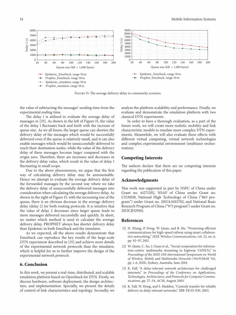
Finally, Figure 15 describes the average delivery delay inboth EmuStack and the simulator. There are two ways ofcalculating the average delay. One way is by dividing thesum of the delay of the messages successfully delivered bythe number of those (delay 1). The other way is by dividingthe sum of the delay of all the messages successfully andunsuccessfully delivered by the number of those (delay 2).Thedelay of those unsuccessfully delivered messages is defined as
14 Mobile Information Systems
Epidemic_EmuStack, range 50mProphet_EmuStack, range 50mEpidemic_simulator, range 50mProphet_simulator, range 50 m
Epidemic_EmuStack, range 50mProphet_EmuStack, range 50m
Queue size (kB = 1,000 bytes)20 80 100 120 140 160 180 20040 60
Queue size (kB = 1,000 bytes)20 80 100 120 140 160 180 20040 60
Del
ay 1
(s)
6000
3000
5000
2000
4000
10000
Del
ay 2
(s)
80009000
70006000
3000
5000
2000
4000
10000
Figure 15: The average delivery delay in community scenario.
the value of subtracting the messages’ sending time from theexperimental ending time.
The delay 1 is utilized to evaluate the average delay ofmassages in [35]. As shown in the left of Figure 15, the valueof the delay 1 fluctuates back and forth with the increase ofqueue size. As we all know, the larger queue can shorten thedelivery delay of the messages which would be successfullydelivered even if the queue is relatively small, and it can alsoenable messages which would be unsuccessfully delivered toreach their destination nodes, while the value of the deliverydelay of these messages become larger compared with theorigin zero. Therefore, there are increases and decreases inthe delivery delay value, which result in the value of delay 1fluctuating in small scope.
Due to the above phenomenon, we argue that the firstway of calculating delivery delay may be unreasonable.Hence we attempt to evaluate the average delivery delay ofthe forwarded massages by the second way where we takethe delivery delay of unsuccessfully delivered messages intoconsideration when calculating the average delivery delay. Asshown in the right of Figure 15, with the increasing size of thequeue, there is an obvious decrease in the average deliverydelay (delay 2) for both routing protocols. It is intuitive thatthe value of delay 2 decreases since larger queue leads tomore messages delivered successfully and quickly. In short,no matter which method is used to calculate the averagedelivery delay, PROPHET always has shorter delivery delaythan Epidemic in both EmuStack and the simulator.
As we expected, all the above results demonstrate thatEmuStack can reproduce the key results of the large-scaleDTN experiment described in [35] and achieve more detailsof the experimental network protocols than the simulator,which is helpful for us to further improve the design of theexperimental network protocol.
6. Conclusion
In this work, we present a real-time, distributed, and scalableemulation platform based on OpenStack for DTN. Firstly, wediscuss hardware, software deployment, the design architec-ture, and implementation. Specially, we present the detailsof control of link characteristics and topology. Secondly, we
analyze the platform scalability and performance. Finally, weevaluate and demonstrate the emulation platform with twoclassical DTN experiments.
In order to have a thorough evaluation, as a part of thefuture work, we will create more realistic mobility and linkcharacteristic models to emulate more complex DTN exper-iments. Meanwhile, we will also evaluate these effects withdifferent virtual computing, virtual network technologiesand complex experimental environment (multiuser orches-tration).
Competing Interests
The authors declare that there are no competing interestsregarding the publication of this paper.
Acknowledgments
This work was supported in part by NSFC of China underGrant no. 61271202, NSAF of China under Grant no.U1530118, National High Technology of China (“863 pro-gram”) under Grant no. 2015AA015702, and National BasicResearch Program of China (“973 program”) under Grant no.2013CB329101.
References
[1] H. Zhang, P. Dong, W. Quan, and B. Hu, “Promoting efficientcommunications for high-speed railway using smart collabora-tive networking,” IEEEWireless Communications, vol. 22, no. 6,pp. 92–97, 2015.
[2] W. Quan, C. Xu, J. Guan et al., “Social cooperation for informa-tion-centric multimedia streaming in highway VANETs,” inProceedings of the IEEE 15th International Symposium on Worldof Wireless, Mobile and Multimedia Networks (WoWMoM ’14),pp. 1–6, IEEE, Sydney, Australia, June 2014.
[3] K. Fall, “A delay-tolerant network architecture for challengedinternets,” in Proceedings of the Conference on Applications,Technologies, Architectures, and Protocols for Computer Commu-nications, pp. 27–34, ACM, August 2003.
[4] K. Fall, W. Hong, and S. Madden, “Custody transfer for reliabledelivery in delay tolerant networks,” IRB-TR 03-030, 2003.
Mobile Information Systems 15
[5] A. P. Silva, S. Burleigh, C. M. Hirata, and K. Obraczka, “A sur-vey on congestion control for delay and disruption tolerant net-works,” Ad Hoc Networks, vol. 25, pp. 480–494, 2015.
[6] M. Liu, Y. Yang, and Z. Qin, “A survey of routing protocols andsimulations in delay-tolerant networks,” inWireless Algorithms,Systems, and Applications, vol. 6843 of Lecture Notes in Com-puter Science, pp. 243–253, Springer, Berlin, Germany, 2011.
[7] Delay Tolerant Networking Research Group, DTNReferenceImplementation, March 2016, https://sites.google.com/site/dtnres-group/home/code.
[8] S. Burleigh, “Interplanetary overlay network an implementationof the DTN bundle protocol,” in Proceedings of the 20074th Annual IEEE Consumer Communications and NetworkingConference (CCNC ’07), pp. 222–226, IEEE, Las Vegas, Nev,USA, January 2007.
[9] S. Schildt, J. Morgenroth, W. B. Pottner et al., “IBRDTN:a lightweight, modular and highly portable Bundle Protocolimplementation,” Electronic Communications of the EASST, vol.37, 2011.
[10] M. J. Khabbaz, C.M.Assi, andW. F. Fawaz, “Disruption-tolerantnetworking: a comprehensive survey on recent developmentsand persisting challenges,” IEEE Communications Surveys &Tutorials, vol. 14, no. 2, pp. 607–640, 2012.
[11] J. A. Fraire and J. M. Finochietto, “Design challenges in contactplans for disruption-tolerant satellite networks,” IEEE Commu-nications Magazine, vol. 53, no. 5, pp. 163–169, 2015.
[12] E. Koutsogiannis, S. Diamantopoulos, and V. Tsaoussidis, “ADTN testbed architecture,” in Proceedings of the InternationalConference on Ultra Modern Telecommunications & Workshops(ICUMT ’09), pp. 1–2, St. Petersburg, Russia, October 2009.
[13] R. Beuran, S. Miwa, and Y. Shinoda, “Network emulation test-bed for DTN applications and protocols,” in Proceedings of the32nd IEEE Conference on Computer Communications (INFO-COM ’13), pp. 3441–3446, Turin, Italy, April 2013.
[14] I. Komnios, I. Alexiadis, N. Bezirgiannidis et al., “SPICEtestbed: a DTN testbed for satellite and space communications,”in Testbeds and Research Infrastructure: Development of Net-works and Communities: 9th International ICSTConference, Tri-dentCom 2014, Guangzhou, China, May 5–7, 2014, Revised Sel-ected Papers, vol. 137 of Lecture Notes of the Institute for Com-puter Sciences, Social Informatics and Telecommunications Engi-neering, pp. 205–215, Springer, Berlin, Germany, 2014.
[15] Docker, https://www.Docker.com/.[16] “TC,” http://www.lartc.org/lartc.html.[17] OpenStack, http://www.openstack.org/.[18] “Ceilometer,” https://launchpad.net/ceilometer.[19] H. Li, H. Zhou, H. Zhang et al., “EmuStack: an openstack-based
DTN network emulation platform,” in Proceedings of the IEEEInternational Conference on Networking and Network Appli-cations (NaNA ’16), pp. 387–392, Hakodate, Japan, July 2016.
[20] M. Hibler, R. Ricci, L. Stoller et al., “Large-scale virtualizationin the emulab network testbed,” in Proceedings of the USENIXAnnual Technical Conference (USENIX ’08), pp. 113–128, Boston,Mass, USA, June 2008.
[21] B. Lantz, B. Heller, and N. McKeown, “A network in a laptop:rapid prototyping for software-defined networks,” in Proceed-ings of the 9th ACM SIGCOMMWorkshop on Hot Topics in Net-works, Monterey, Calif, USA, October 2010.
[22] N. Handigol, B. Heller, V. Jeyakumar, B. Lantz, and N. McK-eown, “Reproducible network experiments using container-based emulation,” in Proceedings of the 8th ACM International
Conference on Emerging Networking Experiments and Technolo-gies (CoNEXT ’12), pp. 253–264, ACM, Nice, France, December2012.
[23] “LXC,” https://linuxcontainers.org/.[24] M. G. Xavier, M. V. Neves, F. D. Rossi, T. C. Ferreto, T. Lange,
and C. A. F. De Rose, “Performance evaluation of container-based virtualization for high performance computing environ-ments,” in Proceedings of the 21st Euromicro International Con-ference on Parallel, Distributed, and Network-Based Processing(PDP ’13), pp. 233–240, March 2013.
[25] “Keystone,” https://wiki.openstack.org/wiki/Keystone.[26] “Horizon,” https://wiki.openstack.org/wiki/Horizon.[27] “Glance,” https://wiki.openstack.org/wiki/Glance.[28] F. Song, D. Huang, H. Zhou, H. Zhang, and I. You, “An
optimization-based scheme for efficient virtual machine place-ment,” International Journal of Parallel Programming, vol. 42, no.5, pp. 853–872, 2014.
[29] “Chrony,” http://chrony.tuxfamily.org/.[30] “NTP,” http://www.ntp.org/.[31] “HTB,” http://luxik.cdi.cz/∼devik/qos/htb/manual/userg.htm.[32] NetEm, http://www.linuxfoundation.org/collaborate/workgroups/
networking/netem.[33] W. Ivancic, W. M. Eddy, L. Wood et al., “Delay/disruption-
tolerant network testing using a LEO satellite,” in Proceedingsof the NASA Earth Science Technology Conference (ESTC ’08),University of Maryland, June 2008.
[34] C. Caini andR. Firrincieli, “Application of contact graph routingto LEO satellite DTN communications,” in Proceedings of theIEEE International Conference onCommunications (ICC ’12), pp.3301–3305, IEEE, Ottawa, Canada, June 2012.
[35] A. Lindgren, A. Doria, and O. Schelen, “Probabilistic routing inintermittently connected networks,” ACM SIGMOBILE MobileComputing and Communications Review, vol. 7, no. 3, pp. 19–20,2003.
[36] A. Vahdat and D. Becker, “Epidemic routing for partially-con-nected ad hoc networks,” Tech. Rep. CS-20000, Duke Univer-sity, 2000.
[37] “STK,” http://www.agi.com/products/stk/.[38] “ION-DTN,” http://sourceforge.net/projects/ion-dtn/.[39] S. C. Burleigh, “CFDP for interplanetary overlay network,”
NASA. Tech Briefs, vol. 35, no. 3, p. 36, 2011.[40] K. L. Scott and S. Burleigh, Bundle protocol specification, 2007.[41] R. Wang, S. C. Burleigh, P. Parikh, C.-J. Lin, and B. Sun, “Lick-
lider transmission protocol (LTP)-basedDTN for cislunar com-munications,” IEEE/ACM Transactions on Networking, vol. 19,no. 2, pp. 359–368, 2011.
[42] S. Burleigh, Contact graph routing, 2010.

Submit your manuscripts athttp://www.hindawi.com
Computer Games Technology
International Journal of
Hindawi Publishing Corporationhttp://www.hindawi.com Volume 2014
Hindawi Publishing Corporationhttp://www.hindawi.com Volume 2014
Distributed Sensor Networks
International Journal of
Advances in
FuzzySystems
Hindawi Publishing Corporationhttp://www.hindawi.com
Volume 2014
International Journal of
ReconfigurableComputing
Hindawi Publishing Corporation http://www.hindawi.com Volume 2014
Hindawi Publishing Corporationhttp://www.hindawi.com Volume 2014
Applied Computational Intelligence and Soft Computing
Advances in
Artificial Intelligence
Hindawi Publishing Corporationhttp://www.hindawi.com Volume 2014
Advances inSoftware EngineeringHindawi Publishing Corporationhttp://www.hindawi.com Volume 2014
Hindawi Publishing Corporationhttp://www.hindawi.com Volume 2014
Electrical and Computer Engineering
Journal of
Journal of
Computer Networks and Communications
Hindawi Publishing Corporationhttp://www.hindawi.com Volume 2014
Hindawi Publishing Corporation
http://www.hindawi.com Volume 2014
Advances in
Multimedia
International Journal of
Biomedical Imaging
Hindawi Publishing Corporationhttp://www.hindawi.com Volume 2014
ArtificialNeural Systems
Advances in
Hindawi Publishing Corporationhttp://www.hindawi.com Volume 2014
RoboticsJournal of
Hindawi Publishing Corporationhttp://www.hindawi.com Volume 2014
Hindawi Publishing Corporationhttp://www.hindawi.com Volume 2014
Computational Intelligence and Neuroscience
Industrial EngineeringJournal of
Hindawi Publishing Corporationhttp://www.hindawi.com Volume 2014
Modelling & Simulation in EngineeringHindawi Publishing Corporation http://www.hindawi.com Volume 2014
The Scientific World JournalHindawi Publishing Corporation http://www.hindawi.com Volume 2014
Hindawi Publishing Corporationhttp://www.hindawi.com Volume 2014
Human-ComputerInteraction
Advances in
Computer EngineeringAdvances in
Hindawi Publishing Corporationhttp://www.hindawi.com Volume 2014