Embed Size (px)
Citation preview
Hindawi Publishing CorporationJournal of Electrical and Computer EngineeringVolume 2013 Article ID 679032 20 pageshttpdxdoiorg1011552013679032
Research ArticleEfficient Joint Estimation and Compensation of CFOTxRx Frequency-Selective IQ Imbalance and the MIMO RadioChannel in OFDM Systems
Jian Luo1 Wilhelm Keusgen2 and Andreas Kortke3
1 Huawei Technologies Duesseldorf GmbH European Research Center (ERC) Riesstraszlige 25 80992 Munich Germany2 Fraunhofer Heinrich Hertz Institute Einsteinufer 37 10587 Berlin Germany3 Technische Universitat Berlin Straszlige des 17 Juni 135 10623 Berlin Germany
Correspondence should be addressed to Jian Luo jianluohuaweicom
Received 23 May 2012 Revised 23 October 2012 Accepted 18 November 2012
Academic Editor Luc Vandendorpe
Copyright copy 2013 Jian Luo et alThis is an open access article distributed under the Creative Commons Attribution License whichpermits unrestricted use distribution and reproduction in any medium provided the original work is properly cited
MIMO OFDM is a very promising technique for future wireless communication systems By applying direct conversionarchitecture low-cost low-power small size and flexible implementation of MIMO OFDM systems can be realized However theperformance of direct conversion architecture-based MIMO OFDM systems can be seriously affected by RF impairments inclingcarrier frequency offset (CFO) and IQ-imbalance While OFDM is sensitive to CFO direct conversion architecture is sensitive toIQ imbalance SuchRF impairments aggravate as the carrier frequency becomes higher for example beyond 60GHz To achieve thedesired high performance ofMIMOOFDM suchRF impairments have to be compensated for In this paper the joint compensationof CFO transmitter and receiver frequency-selective IQ imbalance and the MIMO radio channel is investigated Two preamble-based schemes are proposed for impairment parameter estimation The proposed preambles are constructed both in time andfrequency domains and require much less overhead than the state-of-the-art designs Furthermore much lower computationalcomplexity is allowed enabling efficient implementationThe advantages and effectiveness of both proposed schemes are comparedand verified by numerical simulations and complexity analysis
1 Introduction
MIMO OFDM is one of the most promising techniques forachieving high data rates in future wireless communicationsystems To allow low-cost low-power small size and flexibleimplementation of MIMOOFDM systems direct conversionarchitecture should be applied both at the transmitter (Tx)and the receiver (Rx) However MIMO OFDM systems withdirect conversion architecture are sensitive to RF impair-ments includingCFODC-Offset and IQ imbalance (both atthe Tx and the Rx) Since DC-Offset can be easily suppressedby AC coupling [1] we mainly focus on the investigationof CFO and IQ imbalance While CFO causes commonphase error and inter-carrier interference IQ imbalanceresults in mirror frequency interference Both impairmentsaggravate as the carrier frequency gets higher for examplebeyond 60GHz Furthermore in broadband systems the IQ
imbalance effect is generally frequency selective giving morechallenges to the estimation and compensation
The compensation of CFO and IQ imbalance in SISO-and MIMO OFDM systems has been studied in a numberof works for example [2ndash16] respectively Among them[3ndash5 9 12 14] only considered frequency-independent IQimbalance which is not suitable for broadband wirelesscommunication systems In contrast the other works con-sidered frequency-selective IQ imbalance The work [2]has proposed a nonlinear-least-square-(NLS-) based schemefor CFO estimation and Rx-IQ-imbalance compensationThis scheme requires exhaustive numerical search and thusresults in high computational complexity Improvementshave been made by [6 7 11 15] where a closed-formlinear least square (LLS) estimator and a suboptimal iterativeestimator have been proposed respectively Both schemeshave lower computational complexity than that in [2] In
2 Journal of Electrical and Computer Engineering
[10] perfect CFO estimation was assumed and a per-toneequalization (PTEQ) scheme was proposed for impairmentcompensation However the PTEQ scheme suffers from slowconvergence and high computational complexity In [13]Kalman filter is applied for compensation which can copewith fast fading MIMO channels However this scheme hasthe disadvantage of high pilot overhead (eg ten OFDMsymbols as preamble) Many of the works above including[2 5 6 9 12ndash14] have the additional drawback that onlyRx impairments were considered in the system model Thusif Tx-IQ imbalance is present the schemes of these worksmay suffer from severe performance degradation due tomodel mismatch (some performance comparisons have beenshown in [7]) In [17] blind Rx-IQ imbalance estimationand compensation schemes were proposed When the CFOis sufficiently large these schemes can provide good Rx-IQimbalance estimation even in low SNR region The reason isthat the Rx noise which is influenced by Rx-IQ-imbalanceis also exploited for estimation Recently this scheme hasbeen extended in [18] to include Tx-IQ-imbalance and CFOmitigation for SISO OFDM systems For MIMO OFDMsystems this scheme needs further extension
The most advanced state-of-the-art schemes consider-ing CFO and both Tx- and Rx- frequency-selective IQ-imbalance in MIMO OFDM systems are those in [11 15]as well as in our previous work [16] The drawback of theschemes in [11 15] is that the used preambles are not overheadand interference optimal Moreover the estimation schemesin [11 15] require quite high computational complexity
This paper extends our previous work [16] and presentstwo improved schemes for the joint estimation of CFO Tx-and Rx- frequency-selective IQ-imbalance and the MIMOchannel in OFDM systems These improved schemes arebased on a novel preamble design Note that in this paper wefocus on indoor scenarios and assume block fading channelsfor which preamble-based parameter estimation is mostefficient (When assuming block-fading channels theMIMOchannels as well as CFO and Tx- and Rx-IQ-imbalanceonly need to be estimated once per communication signalframe based on the preamble Afterwards these estimatedparameters can be used for impairment compensation andsignal equalization of the whole signal frame However dueto residual CFO estimation error and phase noise phasetracking may be necessary which is carried out for eachOFDM block)
The novelties of the proposed schemes can be summa-rized as follows
(i) The proposed preamble is used both for the esti-mation of CFO and Rx-IQ-imbalance as well asthe joint estimation of Tx-IQ-imbalance and theMIMO channel In contrast most existing schemesapply different preambles for these two estimationprocedures (eg [6 7 11 15]) Thus compared to thepreambles used in the reference works our preambleis much more overhead efficient
(ii) When designing the preamble the orthogonalitybetween different Tx antennas as well as betweendirect and image channels (see [19]) is taken into
account allowing better estimation accuracy than[11 15]
(iii) The proposed preambles have low crest factor whichenables ldquopreamble power boostingrdquo
(iv) Theproposed estimation schemes requiremuch lowercomputational complexity than those in [11 15]
(v) As most of the existing schemes the CFO estimationand Rx-IQ-imbalance estimationcompensation ofproposed schemes rely on the negative phase rotation(the direction of the phase rotation (caused by CFO)without Rx-IQ-imbalance is referred to as ldquopositiverdquo)in the mirror frequency interference signal causedby Rx-IQ-imbalance As a result small CFOs cancause difficulties for both estimation and compen-sation Conventionally for example in [6 7] ldquohardswitchingrdquo is applied that is CFO values smallerthan a threshold are regarded as zero (correspond-ingly another IQ-imbalance and channel estimationschemes will be applied which are suitable for thecases without CFO) However an improperly chosenthreshold can cause considerable performance degra-dation To solve this problem we have proposed softmetrics which change adaptively with the SNR andallow ldquosoft switchingrdquo
The advantages of the proposed schemes are verified bothby numerical simulation and complexity analysis Comparedto our previous work [16] the extension includes a newscheme and much more extensive simulation results andanalysis Based on the above descriptions the proposedschemes outperform the state-of-the-art schemes and pro-vide very promising options for joint CFO Tx-Rx IQimbalance and channel estimation in indoor MIMO OFDMsystems
This paper is organized as follows Section 2 describesthe system model and the equivalent baseband modelsSection 3 describes the joint compensation structure and thecalculation of compensation coefficients Sections 4 and 5describe two preamble-based parameter estimation schemesSection 6 shows the simulation results Section 7 providescomplexity analysis Section 8 concludes this paper
2 Signal and System Model
Figure 1 shows the MIMO system model considering bothCFO and TxRx frequency-selective IQ-imbalance Thenumbers of Tx and Rx antennas are119873
119879and119873
119877 respectively
The amplitude and phase imbalance at the ith modulator orat the rth demodulator are indicated by 119892
(119894)⟨119903⟩
119879119877and 120593
(119894)⟨119903⟩
119879119877
respectively The impulse response of Tx or Rx low-passFilters (LPF) in the I andQbranches are indicated by ℎ(119894)⟨119903⟩
TIRI (119905)
and ℎ(119894)⟨119903⟩
TQRQ(119905) respectively All different TxRx branches havedifferent IQ-imbalance parameters as well as different LPFimpulse responseThe ordinary carrier frequency is 119891
119888 while
a CFO Δ119891 is present at all Rx demodulators The impulseresponse of the RF components at the ith Tx or the rth Rx aremodeled as ℎ(119894)⟨119903⟩
RFTxRx(119905)The radio channel between the ith Tx
Journal of Electrical and Computer Engineering 3
DAC
LPF
DAC
LPF
LPF
ADC
ADC
LPF
ℎ(119894)TI
ℎ(119894)TQ
cos(2120587119891119888119905)
Tx 119873119879
Rx 119903
Rx 1
Rx 119873119877
119904(119894)im[119899]
119904(119894)re [119899]
minus119892(119894)119879 sin(2120587119891119888119905+120593(119894)119879 )
Tx 1
ℎ(119894)RFTx
Tx 119894
119906(119894)RF(119905)
cos(2120587(119891119888 + Δ119891)119905)
Figure 1 System model with CFO and frequency-selective IQ imbalance
and the rth Rx is modeled by ℎ⟨119903119894⟩
RF (119905) which is assumed to bequasi static (block fading)
For further analysis an equivalent baseband modelshould be derived From Figure 1 the relation between theLPF inputs at Tx 119904(119894)re (119905) and 119904
(119894)
im(119905) and the modulated signal119906(119894)
RF(119905) (shown in Figure 1) can be expressed as
119906RF (119905) = (119904re (119905) lowast ℎTI (119905)) cos (2120587119891119888119905)
minus (119904im (119905) lowast ℎTQ (119905)) 119892119879sin (2120587119891
119888119905 + 120593
119879)
= Re
(119904 (119905) lowast ℎDT (119905) + 119904lowast(119905) lowast ℎIT (119905))⏟⏟⏟⏟⏟⏟⏟⏟⏟⏟⏟⏟⏟⏟⏟⏟⏟⏟⏟⏟⏟⏟⏟⏟⏟⏟⏟⏟⏟⏟⏟⏟⏟⏟⏟⏟⏟⏟⏟⏟⏟⏟⏟⏟⏟⏟⏟⏟⏟⏟⏟⏟⏟⏟⏟⏟⏟⏟⏟⏟⏟⏟⏟
119906(119905)
1198901198952120587119891119888119905
(1)
where 119904(119905) = 119904re(119905) + 119895119904im(119905) and ℎDIT(119905) = (ℎTI(119905) plusmn
119892119879119890119895120593119879ℎTQ(119905))2 with the Tx index 119894 omitted for simplic-
ity Note that 119906(119905) is the complex envelope of 119906RF(119905) Letthe demodulator input signal be expressed as VRF(119905) =
ReV(119905)1198901198952120587119891119888119905 (shown in Figure 1) where the Rx index 119903
is omitted for simplicity The relation between the complexenvelope V(119905) and the IQ ADC input 119910(119905) = 119910re(119905) + 119895119910im(119905)can be expressed as
119910 (119905) = (V (119905) 119890minus1198952120587Δ119891119905
) lowast ℎDR (119905) + (V (119905) 119890minus1198952120587Δ119891119905
)lowast
lowast ℎIR (119905)
(2)
where ℎDIR(119905) = (ℎRI(119905) plusmn 119892119877119890∓119895120593119877ℎRQ(119905))2
Based on (1) and (2) the equivalent discrete time base-band model in Figure 2 can be obtained where ℎ(119894)
DIT[119899] andℎ⟨119903⟩
DIR[119899] are the discrete versions of ℎ(119894)
DIT(119905) and ℎ⟨119903⟩
DIR(119905)respectively Moreover ℎ⟨119903119894⟩
[119899] is the equivalent basebandchannel between the ith Tx and the rth Rx and includesthe effects of ℎ
⟨119903119894⟩
RF (119905) ℎ(119894)
RFTx(119905) and ℎ⟨119903⟩
RFRx(119905) in Figure 1The CFO influence is modeled by the multiplication with119890119895(2120587120598119899119873) where 120598 = minusΔ119891119873119891
119904with 119891
119904as the sampling
frequency (eg Nyquist sampling frequency) Finally 120578⟨119903⟩[119899]
is the additive white Gaussian noise (AWGN) at the rth Rxbranch (equivalent discrete version of the RF frontend noisebut before LPF filtering) with 119864|120578
⟨119903⟩[119899]|
2
= 1205902
n
To further simplify the baseband model we observe thefollowing relation
(119904 [119899] 119890119895(2120587119873)120598119899
) lowast ℎ [119899]
=
infin
sum
119898=minusinfin
ℎ [119898] (119904 [119899 minus 119898] 119890119895(2120587119873)120598(119899minus119898)
)
= (
infin
sum
119898=minusinfin
ℎ [119898] 119890minus119895(2120587119873)120598119898
119904 [119899 minus 119898]) 119890119895(2120587119873)120598119899
= [119904 [119899] lowast (ℎ [119899] 119890minus119895(2120587119873)120598119899
)] 119890119895(2120587119873)120598119899
(3)
where 119904[119899] and ℎ[119899] represent an arbitrary input sequence andan FIR filter respectively Equation (3) implies the equivalentsystem structures in Figure 3 where the following notation isused throughout this paper (similar to [6])
(997888rarr∙ ) = (∙) 119890
minus119895(2120587119873)120598119899 (
larr997888∙ ) = (∙) 119890
119895(2120587119873)120598119899 (4)
By applying the equivalent structure of Figure 3 to theinput-output relation of the baseband model in Figure 2 weobtain the following expression
119910⟨119903⟩
[119899] = 119909⟨119903⟩
D [119899] 119890119895(2120587120598119899119873)
+ 119909⟨119903⟩
I [119899] 119890minus119895(2120587120598119899119873)
+ ⟨119903⟩
[119899]
119909⟨119903⟩
D [119899] =
119873119879
sum
119894=1
119904(119894)[119899] lowast ℎ
⟨119903119894⟩
1[119899] + 119904
(119894)lowast[119899] lowast ℎ
⟨119903119894⟩
2[119899]
119909⟨119903⟩
I [119899] =
119873119879
sum
119894=1
119904(119894)[119899] lowast ℎ
⟨119903119894⟩
3[119899] + 119904
(119894)lowast[119899] lowast ℎ
⟨119903119894⟩
4[119899]
⟨119903⟩
[119899] = 120578⟨119903⟩
[119899] 119890119895(2120587120598119899119873)
ℎ⟨119903⟩
DR [119899]
+ 120578⟨119903⟩lowast
[119899] 119890minus119895(2120587120598119899119873)
ℎ⟨119903⟩
IR [119899]
(5)
with
ℎ⟨119903119894⟩
12[119899] = ℎ
(119894)
DIT [119899] lowast ℎ⟨119903119894⟩
[119899] lowast
997888997888997888997888997888997888rarr
ℎ⟨119903⟩
DR [119899]
ℎ⟨119903119894⟩
34[119899] = ℎ
(119894)lowast
IDT [119899] lowast ℎ⟨119903119894⟩lowast
[119899] lowast
larr997888997888997888997888997888
ℎ⟨119903⟩
IR [119899]
(6)
4 Journal of Electrical and Computer Engineering
middot middot middot
ℎ(119894)D119879[119899]
Tx 119894 IQ imb
Tx 119894channel
Rx 119903 IQ imb
ℎ(119894)I119879[119899]
ℎ(119894)D119877[119899]
ℎ(119894)I119877[119899]
119890119895(2120587119873)120598119899
119904(119894)[119899]
119904(119873T )[119899]
( )lowast( )
lowast
Figure 2 Equivalent baseband model with CFO and IQ imbalance
119890119895(2120587119873)120598119899
ℎ[119899]
119890119895(2120587119873)120598119899
Figure 3 Exchanging the positions of a phase rotator and an FIR filter
where ℎ⟨119903119894⟩
1sim ℎ
⟨119903119894⟩
4are assumed to be of length 119871h FIR
filters Equation (5) yields the simplified baseband model inFigure 4
Finally we remark that although the model of Figure 2can be found in similar mathematical expression in theliterature for example [11 15] the model of Figure 4 is novel(to the best of the authorsrsquo knowledge)
3 Compensation of CFO Frequency-SelectiveIQ-Imbalance and the MIMO Channel
For the compensation of CFO frequency-selective IQ-imbalance and the MIMO channel an extended version ofthe hybrid domain compensation structure in [7] is applied(similar to [11 15]) which is shown in Figure 5 Within eachRx branch Rx-IQ-imbalance and CFO are compensated intime domain Afterwards Tx-IQ-imbalance and the MIMOchannels are compensated in frequency domain
From Figure 5 the Rx signal after Rx-IQ-imbalancecompensation can be expressed as
⟨119903⟩
[119899] = 119910⟨119903⟩
re [119899 minus 119899120591]
+ 119895 (119888119910⟨119903⟩
re [119899 minus 119899120591] + ℎ
119862⟨119903⟩[119899] lowast 119910
⟨119903⟩
im [119899])
(7)
where 119899120591is the dominant-tap index (we assume the index
starts from 0) of the FIR filter ℎ119862⟨119903⟩[119899] which is of length 119871c
Equation (7) can be equivalently written as
⟨119903⟩
[119899] = 119908⟨119903⟩
D [119899] lowast 119910⟨119903⟩
[119899] + 119908⟨119903⟩
I [119899] lowast 119910⟨119903⟩lowast
[119899] (8)
with
119908⟨119903⟩
DI [119899] =1
2(120575 [119899 minus 119899
120591] (1 + 119895119888
⟨119903⟩) plusmn ℎ
119862⟨119903⟩[119899]) (9)
where 120575[119899] is the discrete time impulse function By substi-tuting (5) into (8) we have
⟨119903⟩
[119899] = 119890119895(2120587120598119899119873)
times
119873119879
sum
119894=1
[119904(119894)[119899] lowast ℎ
119864⟨119903119894⟩
D [119899] + 119904(119894)lowast
[119899] lowast ℎ119864⟨119903119894⟩
I [119899]]
+ 119890minus119895(2120587120598119899119873)
times
119873119879
sum
119894=1
[119904(119894)[119899] lowast 120599
119864⟨119903119894⟩
D [119899] + 119904(119894)lowast
[119899] lowast 120599119864⟨119903119894⟩
I [119899]]
+ ⟨119903⟩
[119899]
(10)
ℎ119864⟨119903119894⟩
DI [119899] = ℎ⟨119903119894⟩
12[119899] lowast
997888997888997888997888997888997888rarr
119908⟨119903⟩
D [119899]
+ ℎ⟨119903119894⟩lowast
43[119899] lowast
997888997888997888997888997888997888rarr
119908⟨119903⟩
I [119899]
120599119864⟨119903119894⟩
DI [119899] = ℎ⟨119903119894⟩
34[119899] lowast
larr997888997888997888997888997888997888
119908⟨119903⟩
D [119899]
+ ℎ⟨119903119894⟩lowast
21[119899] lowast
larr997888997888997888997888997888997888
119908⟨119903⟩
I [119899]
(11)
where ⟨119903⟩[119899] is the noise after Rx-IQ-imbalance compen-
sation From Figure 2 we can see that the phase rotation119890minus119895(2120587120598119899119873) in (5) and (10) is caused by the Rx-IQ-imbalanceThus after Rx-IQ-imbalance compensation all signal com-ponents in (10) having the 119890minus119895(2120587120598119899119873) phase rotation shouldbe eliminated that is
120599119864⟨119903119894⟩
D [119899] = 0 120599119864⟨119903119894⟩
I [119899] = 0 forall119894 (12)
With (6) and (9) it can be proved that the two equationsin (12) are equivalent We will show in Section 43 that from(11) (12) and the estimates of 120598 and ℎ
⟨119903119894⟩
1[119899] sim ℎ
⟨119903119894⟩
4[119899]
the Rx-IQ-imbalance compensation coefficients 119888⟨119903⟩ and
ℎ119862⟨119903⟩
[119899] for all 119903 can be computed
Journal of Electrical and Computer Engineering 5
119890minus119895(2120587119873)120598119899
119890119895(2120587119873)120598119899119904(119894)[119899]
119904(119873T )[119899]
119904(119894)[119899]
119904(119873T )[119899]
( )lowast
( )lowast
middot middot middot
middot middot middot
12
34
D
I
D
I
Figure 4 Simplified baseband model with CFO and frequency-selective IQ imbalance
Other Rx branches
Rx-IQ imb comp
Frequency
domain joint
compensation
Tx-IQ imb
MIMO ch
and
CFO comp
DFT
re
im
Figure 5 Hybrid domain compensation structure
After successful compensation of Rx-IQ-imbalance andCFO the signal ⟨119903⟩
[119899] in Figure 5 can be expressed as
⟨119903⟩
[119899] =
119873119879
sum
119894=1
(119904(119894)[119899] lowast ℎ
119864⟨119903119894⟩
D [119899] + 119904(119894)lowast
[119899] lowast ℎ119864⟨119903119894⟩
I [119899])
+ ⟨119903⟩
[119899]
(13)
where ⟨119903⟩[119899] is the corresponding noise term
Let 119904(119894)119887[119899] for all 119899 isin [0119873 minus 1] be the bth transmitted
OFDM symbol at the ith Tx antenna and let ⟨119903⟩
119887[119899] for all
119899 isin [0119873 minus 1] be the corresponding received OFDM symbolafter Rx-IQ-imbalance and CFO compensation Their DFTsare indicated by 119878
(119894)
119887[119896] and
⟨119903⟩
119887[119896] respectively Assuming
sufficient cyclic prefix (CP) length119873CP (13) yields
⟨119903⟩
119887[119896] =
119873119879
sum
119894=1
(119878(119894)
119887[119896]119867
119864⟨119903119894⟩
D [119896] + 119878(119894)lowast
119887[minus119896]119867
119864⟨119903119894⟩
I [119896])
+ ⟨119903⟩
[119896]
(14)
where 119867119864⟨119903119894⟩
DI [119896] = F119873ℎ
119864⟨119903119894⟩
DI [119899] Equation (14) canbe rewritten in different matrix equations for all possibleantenna diversity or spatial multiplexing schemes accordingto [19] Based on these matrix equations various equalization
techniques for example zero forcing andMMSE can be usedto recover the original data symbols In the following we willshow how to obtain the compensation coefficients based onnovel preamble designs
4 Joint Estimation Scheme 1 Closed-FormCFO Estimation-Based Method
This scheme is developed based on the baseband model ofFigure 4 First a special preamble is applied to estimate 120598 andℎ⟨119903119894⟩
1[119899] sim ℎ
⟨119903119894⟩
4[119899] Based on the estimates of 120598 and ℎ⟨119903119894⟩
1[119899] sim
ℎ⟨119903119894⟩
4[119899] all required coefficients for the compensation ofCFO
and IQ-imbalance can be calculated
41 Preamble Design Inspired by [5] the proposed preambleconsists of a 3-fold repetition of a basic sequence 119904
(119894)[119899] 119899 =
0 119873119875minus1 which is constructed according to the frequency
domain separation (FDS) design in [19] and varies fordifferent Tx antennas To distinguish the preamble fromthe data signals all signals in Figure 4 are extended withthe notation ( ∙) The 3-fold repetition structure is used toestimate 120598 ⟨119903⟩
D [119899] and ⟨119903⟩
I [119899] in Figure 4 Based on ⟨119903⟩
D [119899]
and 119904(119894)[119899] ℎ⟨119903119894⟩
1[119899] and ℎ⟨119903119894⟩
2[119899] can be estimated while based
on ⟨119903⟩
I [119899] and 119904(119894)[119899] ℎ⟨119903119894⟩
3[119899] and ℎ
⟨119903119894⟩
4[119899] can be estimated
Since 3-fold repetition is applied we should minimizethe length of the basic sequence 119873
119875 to minimize the
preamble overhead To apply the FDS design in [19] 119904(119894)[119899] is
constructed as an OFDM symbol with119873119875subcarriers where
119873119875could be different from the number of subcarriers in
the data OFDM symbols 119873 Let (119894)[119896] = F119873119875
119904(119894)[119899] As
mentioned above 119904(119894)[119899] is used to estimate 2119873
119879equivalent
channel impulse response of length 119871h (ie ℎ⟨119903119894⟩
13[119899] and
ℎ⟨119903119894⟩
24[119899]) Thus at least 2119873
119879119871h subcarriers should be active
within (119894)
[119896] In order to reserve the same guardband as theOFDM data symbols we should have 119873
119875ge 2119873
119879119871h119873119873
119863
6 Journal of Electrical and Computer Engineering
To facilitate the FFT implementation we choose 119873119875
=
2lceillog2(2119873119879119871h119873119873
119863+119873a)rceil where119873a is a number to adjust119873
119875 The
number of null subcarriers in the basic sequence is 1198730119875
=
lceil119873119875119873119873
119863rceil while the number of active subcarriers is119873
119863119875=
119873119875minus 119873
0119875 Now the active subcarriers can be allocated to
different Tx antennas according to the FDS design in [19]We denote by I
119894in |I
119894| = 119871
1015840 the index set of the allocatedsubcarriers for the ith Tx According to the FDS design in[19] the index sets I
119894 for all 119894 should fulfill the following
interference avoidance requirements(1) I
119894 for all 119894 is an equidistant subcarrier set so that
intertap interference of the estimated channel impulseresponse can be avoided
(2) I1198940
capI1198941
= 0 for all 1198940
= 1198941 to avoid inter-Tx-antenna
interference(3) I
1198940
cap(minusI1198941
) = 0 for all 1198940 119894
1 to avoid the interference
between direct and image channelsBy assigning values of a length of 1198711015840 constant amplitude zeroauto correlation (CAZAC) sequence 119879(119894)
(120581)with |119879(119894)(120581)| = 1
to the allocated subcarriers of each basic sequence that is
(119894)
[(I119894)120581] = 119879
(119894)(120581) forall120581 = 0 119871
1015840minus 1
(119894)
[119896] = 0 forall119896 notin I119894
(15)
low crest factor of the basic sequence can be achieved (Fora CAZAC sequence the crest factor remains constant afterDFT or IDFT Assigning the values of a CAZAC sequenceto partially equidistant subcarriers with distance 119889 can beinterpreted as a 119889-fold repetition phase rotation (constantphase difference between neighboring samples) and frac-tional oversampling (due to guardband reservation) of theIDFT of the original CAZAC sequence All these operationshave negligible effect on the crest factor Note that not thecrest factor of the discrete sequence but of the correspondinganalog baseband signal is used as criterion) Finally the totallength of the preamble is119873CP + 3119873
119875
42 Estimation Scheme
421 Closed-Form Estimation of CFO Let ⟨119903⟩
119887[119899] be the
received signal of the bth repetition of the basic sequenceEquation (5) yields the following expression
⟨119903⟩
119887[119899] =
⟨119903⟩
D [119899] 119890119895(2120587120598119873
119875(119887minus1)119873)
+ ⟨119903⟩
I [119899] 119890minus119895(2120587120598119873
119875(119887minus1)119873)
+ 120578⟨119903⟩
119887[119899]
forall119899 = 0 119873119875minus 1
with ⟨119903⟩
D [119899] = ⟨119903⟩
D [119899] 119890119895(2120587120598119899119873)
⟨119903⟩
I [119899] = ⟨119903⟩
I [119899] 119890minus119895(2120587120598119899119873)
(16)
With 119887 = 1 2 3 (16) yields 3 equations According to [5]if we ignore the noise term the followingmatrix equation canbe obtained
y22 cosΩ = y
13 (17)
where
Ω =2120587120598119873
119875
119873
y2= [(y⟨1⟩
2)119879
(y⟨119873119877⟩2
)119879
]
119879
y13
= [(y⟨1⟩1
+ y⟨1⟩3)119879
(y⟨119873119877⟩1
+ y⟨119873119877⟩3
)119879
]
119879
y⟨119903⟩119887
= [⟨119903⟩
119887[0]
⟨119903⟩
119887[119873
119875minus 1]]
119879
(18)
The least-square estimation (LSE) of cosΩ is
cosΩ =1
2Re (y
2)daggery
13 =
1
21003817100381710038171003817y2
1003817100381710038171003817
2
2
Re (y2)119867y
13 (19)
which yields the following closed-form estimator (CLFE)
= plusmn119873
2120587119873119875
cosminus1 (cosΩ) (20)
Note that (20) is the extension of the estimator in[5 (Equation (15)] to exploit the Rx array gain and diversitygain The sign ambiguity in (19) can be solved by taking thesign of the following rough CFO estimator
rough
=119873
2120587119873119875
arg [y1198791 y119879
2]lowast
[y1198792 y119879
3]119879
(21)
422 Separation of ⟨119903⟩
D [119899] and ⟨119903⟩
I [119899] To obtain estimates of⟨119903⟩
DI[119899] ⟨119903⟩
D [119899] and ⟨119903⟩
I [119899] should be obtained first For thispurpose we rewrite (16) into the following matrix form
[[[
[
(y⟨119903⟩1)119879
(y⟨119903⟩2)119879
(y⟨119903⟩3)119879
]]]
]⏟⏟⏟⏟⏟⏟⏟⏟⏟⏟⏟⏟⏟⏟⏟⏟⏟⏟⏟
Y⟨119903⟩
= [
[
1 1
119890119895Ω
119890minus119895Ω
1198901198952Ω
119890minus1198952Ω
]
]⏟⏟⏟⏟⏟⏟⏟⏟⏟⏟⏟⏟⏟⏟⏟⏟⏟⏟⏟⏟⏟⏟⏟⏟⏟⏟⏟
fΩ
[
[
(z⟨119903⟩D )119879
(z⟨119903⟩I )119879]
]⏟⏟⏟⏟⏟⏟⏟⏟⏟⏟⏟⏟⏟⏟⏟⏟⏟⏟⏟
Z⟨119903⟩
+
[[[[[
[
( 120578⟨119903⟩
1)
119879
( 120578⟨119903⟩
2)
119879
( 120578⟨119903⟩
3)
119879
]]]]]
]⏟⏟⏟⏟⏟⏟⏟⏟⏟⏟⏟⏟⏟⏟⏟⏟⏟⏟⏟
n⟨119903⟩
(22)
where z⟨119903⟩DI = [⟨119903⟩
DI[0] ⟨119903⟩
DI[119873119875minus 1]]
119879
and 120578⟨119903⟩
119887=
[ 120578⟨119903⟩
119887[0] 120578
⟨119903⟩
119887[119873
119875minus 1]]
119879
Now Z⟨119903⟩ can be estimated by
Z
⟨119903⟩
= A⟨119903⟩Y
⟨119903⟩
(23)
where A⟨119903⟩ is a 2 times 3matrix and can be obtained by applyingthe following two different criteria
(1) Minimization of the cost functionZ⟨119903⟩
minus A⟨119903⟩Y⟨119903⟩
2
119865
In this case we have
A⟨119903⟩= (f
Ω)dagger forall119903 (24)
which corresponds to an LSE (this is true only whenΩ is perfectly known)
Journal of Electrical and Computer Engineering 7
(2) Minimization of the cost function119864Z
⟨119903⟩
minus A⟨119903⟩Y⟨119903⟩
2
119865 In this case we have
A⟨119903⟩= D
⟨119903⟩f119867
Ω(f
ΩD
⟨119903⟩f119867
Ω+
1
120588⟨119903⟩I3)
minus1
(25)
where 120588⟨119903⟩ is the Rx SNR at the rth Rx antenna and D⟨119903⟩=
diag[119875⟨119903⟩
D 119875⟨119903⟩ 119875
⟨119903⟩
I 119875⟨119903⟩] with 119875
⟨119903⟩
DI = (1119873119875)119864(z⟨119903⟩DI)
119867
z⟨119903⟩DI
and 119875⟨119903⟩
= 119875⟨119903⟩
D + 119875⟨119903⟩
I By assuming an approximatevalue for the Rx image rejection ratio (IRR) 120592
⟨119903⟩=
119875⟨119903⟩
D 119875⟨119903⟩
I at all Rx branches (the Rx IRR is defined assum
119871hminus1119899=0
|ℎ⟨119903⟩
DR[119899]|2
sum119871hminus1119899=0
|ℎ⟨119903⟩
IR[119899]|2
and reflects the relationbetween the desired signal and the mirror)) we can approx-imate D⟨119903⟩ with D = diag[( + 1) 1( + 1)] for all 119903Thus A⟨119903⟩ becomes independent of 119903 The estimation using(25) corresponds to a linear minimum mean square error(LMMSE)
In Section 6 the performance of the two estimators above
will be compared based on simulation results Now with Z
⟨119903⟩
and we can easily obtain estimates of ⟨119903⟩
DI[119899] from (16)
423 Estimation of ℎ⟨119903119894⟩
1[119899] sim ℎ
⟨119903119894⟩
4[119899] Let x⟨119903⟩
DI =
[⟨119903⟩
DI[0] ⟨119903⟩
DI[119873119875minus 1]]
119879
and X⟨119903⟩
DI = F119873119875 x⟨119903⟩
DI Accordingto (5) ℎ⟨119903119894⟩
12[119899] can be estimated with
⟨119903⟩
D [119899] while ℎ⟨119903119894⟩
34[119899]
with ⟨119903⟩
I [119899] Similar to the FDS estimation scheme in [19] thefollowing relation can be obtained (when ignoring noise)
X⟨119903⟩
DII119894
=T(119894)F119873119875
(I119894 Lh)h⟨119903119894⟩
13 X⟨119903⟩
DIminusI119894
= T(119894)lowast
F119873119875
(minusI119894 Lh)h⟨119903119894⟩
24
(26)
where
T(119894)= diag [119879(119894)
[0] 119879(119894)[119871
1015840minus 1]]
T(119894)
= diag [119879(119894)[119871
1015840minus 1] 119879
(119894)[0]]
h⟨119903119894⟩
1234= [ℎ
⟨119903119894⟩
1234[0] ℎ
⟨119903119894⟩
1234[119871h minus 1]]
119879
Lh = 0 119871h minus 1
(27)
Correspondingly h⟨119903119894⟩
1234can be estimated with the following
two methods
(1) Maximum likelihood estimation (MLE)
h⟨119903119894⟩
13= (F119873
119875
(I119894 Lh))
dagger
T(119894)lowastX⟨119903⟩
DII119894
h(119894)
24= (F119873
119875
(minusI119894 Lh))
dagger
T(119894)
X⟨119903⟩
DIminusI119894
(28)
(2) LMMSE
h⟨119903119894⟩
13= Q
(119894)
D T(119894)lowastX⟨119903⟩
DII119894
h(119894)
24= Q
(119894)
I T(119894)
X⟨119903⟩
DIminusI119894
(29)
with
Q(119894)
D = ((F119873119875
(I119894 Lh))
119867
F119873119875
(I119894 Lh)+
119871h120588⟨119903⟩
I119871h)
minus1
(F119873119875
(I119894 Lh))
119867
Q(119894)
I = ((F119873119875
(minusI119894 Lh))
119867
F119873119875
(minusI119894 Lh)+
119871h120588⟨119903⟩
I119871h)
minus1
(F119873119875
(minusI119894 Lh))
119867
(30)
where 120588⟨119903⟩ is the SNR at each Rx antenna To reducecomplexity a fixed value can be assumed for 120588⟨119903⟩ Inthis case both Q
(119894)
D T(119894)lowast and Q(119894)
I T(119894)
can be regardedas known (ie can be precomputed)
424 Soft Switching Method for Critical CFO Values Inpractice when Ω rarr 0 and Ω rarr plusmn120587 the CLFE in (20)will suffer from high sensitivity to noise [5] Moreover thecondition number of f
Ωwill become very large resulting in
large estimation error for z⟨119903⟩DI Section 6will show that in suchcases the rough estimator rough will be much more accuratethan the CLFE Thus the rough estimator should be usedMoreover instead of applying (23) we should set
z⟨119903⟩D =1
3(y⟨119903⟩
1+ y⟨119903⟩
3+ sgn (cos Ω) y⟨119903⟩
2) z⟨119903⟩I = 0
119873119875times1
(31)
which implies that the Rx-IQ-imbalance will not be sepa-rately compensated for but jointly with the Tx-IQ-imbalanceand theMIMOchannel For the detection of such cases (Ω rarr
0 andΩ rarr plusmn120587) we observe the relation
1
119873119877119873
119875
119864 1003817100381710038171003817y13 minus 2 sgn (cosΩ) y
2
1003817100381710038171003817
2
2 ge 6
2
n (32)
which follows from (22) (we assume 119864|⟨119903⟩[119899]|
2
= 2
n) Theequality applies when Ω = 0 or Ω = plusmn120587 Accordingly we candefine the following metric
119875Δ=
1
119873119877119873
119875
1003817100381710038171003817y13 minus 2 sgn (cosΩ) y2
1003817100381710038171003817
2
2minus 6120577
2
n (33)
where 120577 ge 1 is an adjusting factor Once 119875Δ
lt 0 both
rough and (31) are applied Otherwise we apply f
Ω
Z
2
119865
which corresponds to the power of the signal part in (22)as a further metric to switch between and
rough whereZ = [
Z
⟨1⟩
Z
⟨119873119877⟩
] The estimator that leads to a larger
fΩ
Z
2
119865is chosen Compared to [7] the metrics above allow
soft switching
425 Iterative Improvement To further improve the CFOestimation and the separation of
⟨119903⟩
D [119899] and ⟨119903⟩
I [119899] thefollowing iterative processing can be applied
(1) y⟨119903⟩119887
= y⟨119903⟩119887
minus z⟨119903⟩I 119890minus119895Ω(119887minus1) for all 119887 119903 is calculated to
eliminate the influence of Rx-IQ-imbalance on thereceived preamble
8 Journal of Electrical and Computer Engineering
(2) equation (21) is applied with y119887instead of y
119887to obtain
a new estimate of 120598(3) with the new estimate of 120598 (23) is used to obtain a new
version of Z⟨119903⟩
for all 119903
The above calculation can be carried out iteratively untila predefined allowable iteration number is exceeded
43 Calculation of Compensation Coefficients Now we havethe estimates of 120598 and ℎ
⟨119903119894⟩
1[119899] sim ℎ
⟨119903119894⟩
4[119899] According
to Section 3 successful Rx-IQ-imbalance compensationrequires the fulfillment of the two conditions in (12) Sinceboth conditions are equivalent we only have to choose one ofthem We consider that with realistic IQ-imbalance param-eters ℎ(119894)⟨119903⟩
DTR[119899] would have much larger power gain thanℎ(119894)⟨119903⟩
ITR [119899] Thus according to (6) ℎ⟨119903119894⟩
1[119899] would have much
larger power gain than ℎ⟨119903119894⟩
234[119899] and can be estimated with
much lower estimation error (caused by noise) According to(10) 120599119864⟨119903119894⟩
I [119899] consists partly of ℎ⟨119903119894⟩
1[119899] Thus it should be
used to obtain reliable compensation coefficients From (4)(9) and (12) we obtain
(1 + 119895119888⟨119903⟩) 120574
⟨119903119894⟩
1[119899] + ℎ
119862⟨119903⟩[119899] lowast 120574
⟨119903119894⟩
2[119899] = 0 forall119894 (34)
with
120574⟨119903119894⟩
1[119899] = (ℎ
⟨119903119894⟩lowast
1[119899 minus 119899
120591] + ℎ
⟨119903119894⟩
4[119899 minus 119899
120591]) 119890
minus119895(2120587119873)120598(119899minus119899120591)
120574⟨119903119894⟩
2[119899] = (minusℎ
⟨119903119894⟩lowast
1[119899] + ℎ
⟨119903119894⟩
4[119899]) 119890
minus119895(2120587120598119899119873)
(35)
Equation (34) can be rewritten with real-valued signals as
minus 120574⟨119903119894⟩
1re [119899] = minus119888120574⟨119903119894⟩
1im [119899] + ℎ119862⟨119903⟩
[119899] lowast 120574⟨119903119894⟩
2re [119899] forall119894
minus 120574⟨119903119894⟩
1im [119899] = 119888120574⟨119903119894⟩
1re [119899] + ℎ119862⟨119903⟩
[119899] lowast 120574⟨119903119894⟩
2im [119899] forall119894
(36)
Let 119881ReIm⟨119903119894⟩
12[119896] = F
119873119875
120574⟨119903119894⟩
12reim[119899] and 119867119862⟨119903⟩
[119896] =
F119873119875
ℎ119862⟨119903⟩
[119899] Equation (36) yields
[[[[[[[
[
minus119881Re⟨1199031⟩1
[119896]
minus119881Im⟨1199031⟩
1[119896]
minus119881
Re⟨119903119873119879⟩
1[119896]
minus119881Im⟨119903119873
119879⟩
1[119896]
]]]]]]]
]⏟⏟⏟⏟⏟⏟⏟⏟⏟⏟⏟⏟⏟⏟⏟⏟⏟⏟⏟⏟⏟⏟⏟⏟⏟⏟⏟⏟⏟⏟⏟
120584⟨119903⟩
119896
=
[[[[[[[[[
[
minus119881Im⟨1199031⟩
1[119896] 119881
Re⟨1199031⟩2
[119896]
119881Re⟨1199031⟩1
[119896] 119881Im⟨1199031⟩
2[119896]
minus119881Im⟨119903119873
119879⟩
1[119896] 119881
Re⟨119903119873119879⟩
2[119896]
119881Re⟨119903119873
119879⟩
1[119896] 119881
Im⟨119903119873119879⟩
2[119896]
]]]]]]]]]
]⏟⏟⏟⏟⏟⏟⏟⏟⏟⏟⏟⏟⏟⏟⏟⏟⏟⏟⏟⏟⏟⏟⏟⏟⏟⏟⏟⏟⏟⏟⏟⏟⏟⏟⏟⏟⏟⏟⏟⏟⏟⏟⏟⏟⏟⏟⏟⏟⏟⏟⏟⏟⏟⏟⏟⏟⏟⏟⏟
Θ⟨119903⟩
119896
[119888⟨119903⟩
119867119862⟨119903⟩
[119896]]
⏟⏟⏟⏟⏟⏟⏟⏟⏟⏟⏟⏟⏟⏟⏟⏟⏟⏟⏟⏟⏟
120582⟨119903⟩
119896
(37)
Thus 120582⟨119903⟩119896
can be estimated by
⟨119903⟩
119896= (Θ
⟨119903⟩
119896)dagger
120584⟨119903⟩
119896 (38)
Afterwards 119888⟨119903⟩ and ℎ119862⟨119903⟩
[119899] can be calculated by
⟨119903⟩
=1
119873119863119875
sum
119896isinI119863119875
(⟨119903⟩
119896)1
h119862⟨119903⟩
= (F(I119863119875
L))dagger
H119862
I119863119875
(39)
with I119863119875
= minus119873119863119875
2 minus1 1 119873119863119875
2 h119862⟨119903⟩=
[ℎ119862⟨119903⟩
[0] ℎ119862⟨119903⟩
[119871c minus 1]]119879
L = 0 119871c minus 1 andH119862⟨119903⟩
is a length 119873119875column vector with (H119862⟨119903⟩
)119896
= 119867119862⟨119903⟩
[119896]Note that Tx antenna diversity is exploited in this calculationMoreover the influence of guardband is taken into accountin (39) Finally since119881ReIm⟨119903119894⟩
12[119896] is a conjugate symmetrical
function of 119896 the calculation of (38) only needs to be carriedout for 1 le 119896 le 119873
1198631198752
To further reduce computational complexity the DFTblock size of 119881ReIm⟨119903119894⟩
12[119896] can be reduced to a number 119873V
which just has to be larger than 119871h + 119871c + 119899120591 Furthermore
instead of I119863119875
a proper subcarrier index set I119863119881
with|I
119863119881| = 119873
119863119881 should be defined according to the guard-
band size and the sampling rateFinally with (10) and (9) we can calculate ℎ119864⟨119903119894⟩
DI [119899] thatis also119867119864⟨119903119894⟩
DI [119896]
5 Joint Estimation Scheme 2Iterative CFO and Rx-IQ-ImbalanceEstimation Method
This scheme is developed directly based on the compensationstructure in Figure 5 This scheme uses a similar preambleFirst the preamble is applied to estimate 120598 119888⟨119903⟩ and ℎ
119862⟨119903⟩[119899]
in an iterative manner Afterwards the influence of the CFOand Rx-IQ-imbalance on the preamble is eliminated Finallythe coefficients119867119864⟨119903119894⟩
DI [119896] are calculatedNote that the basic idea of the CFO and Rx-IQ-
imbalance estimation is similar to that in [15] However ourscheme is developed based on anRx-IQ-imbalance compen-sation structure with real-valued coefficients which allowsmuch lower computational complexity (both for parameterestimation and the actual compensation)Moreover practicalextension is developed to cope with the troublesome cases ofcritical CFO values that isΩ rarr 0 andΩ rarr plusmn120587
51 Preamble Design This scheme applies a similar preambledesign as in Section 41 The same basic sequence is appliedfor each Tx antenna However the repetition number of thisbasic sequence can be as low as two Let119873rep be the numberof repetitions then the total length of the preamble is119873CP +119873rep lowast 119873
119875
Journal of Electrical and Computer Engineering 9
52 Estimation Scheme
521 Iterative CFO and Rx-IQ-Imbalance Estimation Forsimplicity of description we first assume that 119873rep = 2 Theextension to preambles with 119873rep gt 2 will be shown laterSimilar to Section 42 ⟨119903⟩
119887[119899] indicates the received signal
of the bth repetition of the basic sequence This estimationscheme is based on the observation that assuming perfectCFO knowledge perfect Rx-IQ-imbalance compensationcoefficients and no noise we have for each Rx- antenna
(y⟨119903⟩re1 + 119895Y⟨119903⟩
CB1hCExt⟨119903⟩
) 119890119895Ω
= y⟨119903⟩re2 + 119895Y⟨119903⟩
CB2hCExt⟨119903⟩
(40)
with
Y⟨119903⟩
CB119887 = [y⟨119903⟩re119887 Y⟨119903⟩
im119887] hCExt⟨119903⟩
= [119888⟨119903⟩ (hC⟨119903⟩
)119879
]
119879
(41)
where Y⟨119903⟩
im119887is an119873
119875times119871c Toeplitz matrix with the 119899th
120591column
equal to y⟨119903⟩im119887
Equation (40) can be rewritten as
[y⟨119903⟩re1 cosΩ minus y⟨119903⟩re2
y⟨119903⟩re1 sinΩ]
⏟⏟⏟⏟⏟⏟⏟⏟⏟⏟⏟⏟⏟⏟⏟⏟⏟⏟⏟⏟⏟⏟⏟⏟⏟⏟⏟⏟⏟⏟⏟⏟⏟⏟⏟⏟⏟
T⟨119903⟩120598
= [Y⟨119903⟩
CB1 sinΩY⟨119903⟩
CB2 minus Y⟨119903⟩
CB1 cosΩ]
⏟⏟⏟⏟⏟⏟⏟⏟⏟⏟⏟⏟⏟⏟⏟⏟⏟⏟⏟⏟⏟⏟⏟⏟⏟⏟⏟⏟⏟⏟⏟⏟⏟⏟⏟⏟⏟⏟⏟⏟⏟
R⟨119903⟩120598
hCExt⟨119903⟩
(42)
According to (42) if 120598 is knownhCExt⟨119903⟩ can be estimatedby
hCExt⟨119903⟩
= R⟨119903⟩
120598
dagger
T⟨119903⟩
120598 (43)
Thus we first carry out an initial CFO estimation by
init
=119873
2120587119873119875
arg (y1198791)lowast
y2 (44)
where y119887 for all 119887 = 1 2 is defined as in Section 42
Afterwards the initial CFO estimate is applied to (43) toobtain an initial estimate of hCExt⟨119903⟩ for all 119903 which is usedto carry out Rx-IQ-imbalance compensation on the receivedpreambles as follows
y⟨119903⟩119887
= y⟨119903⟩re119887 + 119895Y⟨119903⟩
CB119887hCExt⟨119903⟩
(45)
Now the operation in (44) is applied again but withy⟨119903⟩119887
instead of y⟨119903⟩119887 to obtain a new estimate of 120598 This
new CFO estimate is applied again to (43) to obtain a newestimate of hCExt⟨119903⟩ for all 119903 Afterwards Rx-IQ-imbalancecompensation is carried out with this new estimate Thisprocess is repeated iteratively until a predefined allowableiteration number is exceeded
522 Estimation of ℎ119864⟨119903119894⟩
D [119899] 119886119899119889 ℎ119864⟨119903119894⟩
I [119899] After all itera-tions a final CFO and Rx-IQ-imbalance compensation iscarried out on the received preamble sequences according to
Figure 5 We denote the received preamble sequences afterthis compensation as y⟨119903⟩
119887 First we carry out averaging over
the two repetitions to mitigate noise influence
y⟨119903⟩ = 1
2
2
sum
119887=1
y⟨119903⟩119887 (46)
Let Y⟨119903⟩
= F119873119875 y⟨119903⟩ If we ignore the noise influence the
following relation exists
Y⟨119903⟩
I119894
= T(119894)F119873119875
(I119894 Lh)h119864⟨119903119894⟩
D Y⟨119903⟩
minusI119894
= T(119894)lowast
F119873119875
(minusI119894 Lh)h119864⟨119903119894⟩
I
(47)
Finally we can obtain h119864⟨119903119894⟩
D and h119864⟨119903119894⟩
I either using MLE
h119864⟨119903119894⟩
D = (F119873119875
(I119894 Lh))
dagger
T(119894)lowastY⟨119903⟩
I119894
h119864⟨119903119894⟩
I = (F119873119875
(minusI119894 Lh))
dagger
T(119894)
Y⟨119903⟩
minusI119894
(48)
or using LMMSE
h119864⟨119903119894⟩
D = Q(119894)
D T(119894)lowastY⟨119903⟩
I119894
h119864⟨119903119894⟩
I = Q(119894)
I T(119894)
Y⟨119903⟩
minusI119894
(49)
whereQDI is defined as in (30) Finally we calculate
119864⟨119903119894⟩
DI [119896] = F119873ℎ
119864⟨119903119894⟩
DI [119899] (50)
523 Soft Switching Method for Critical CFO Values Similarto the scheme in Section 42 the estimation scheme previouswill have poor performance when Ω rarr 0 or Ω rarr plusmn120587 Thereason is that this scheme utilizes the negative phase rotationcaused by CFO to identify the Rx-IQ-imbalance character-istic However this identification is impossible when Ω = 0
orΩ = plusmn120587 Actually if we ignore the noise in these casesR⟨119903⟩
120598
and T⟨119903⟩
120598in (43) will become zero valued
To avoid this problem we observe the following relation
1
119873119875
119864 10038171003817100381710038171003817y1119890119895Ω
minus y2
10038171003817100381710038171003817
2
2 ge 2
2
n (51)
from which the following soft-metric can be defined
1198751015840
Δ=
1
119873119875
10038171003817100381710038171003817y1119890119895(2120587119873
119875119873)
minus y2
10038171003817100381710038171003817
2
2minus 2120577
2
n (52)
with 120577 as an adjusting factor If 1198751015840
Δgt 0 the iterative
estimation scheme can be applied However if 1198751015840
Δle 0 we
can assume that Ω rarr 0 or Ω rarr plusmn120587 In this case weshould omit the iterative estimation Moreover the initialCFO estimation is used to carry out CFO correction on thereceived preamble as in the case without Rx-IQ-imbalanceBased on the corrected preamble joint Tx- and Rx-IQ-imbalance andMIMO channel estimation is carried out withthe FDS-preamble-based scheme in [19]This implies that noseparate Rx-IQ-imbalance compensation is applied
10 Journal of Electrical and Computer Engineering
The proposed estimation scheme can be easily applied topreambles containing more than two repetitions of the basicsequence To enable this we just need to reorder the multiplebasic repetitions into two augmented repetitions These twoaugmented repetitions are allowed to have overlapped areas
6 Simulation Results
61 Simulation Setups In the simulation the amplitude andphase imbalance of the modulatordemodulator are about5 and 5
∘ respectively The LPFs in the I and Q branches(in all TxRx branches) have relative amplitude mismatchand phase differences of up to 10 and 10
∘ respectively Alldifferent Tx and Rx branches have different IQ-imbalanceparameters All imbalance parameters are assumed to betime invariant Furthermore the measured 60GHz MIMOchannels in [20] were used The following OFDM parametersets are investigated119873 = 256 119873
0= 17 and119873 = 512 119873
0=
91 Furthermore we apply 119873119879= 2119873
119877= 2 119871h = 32 and
119871c = 8 Both the closed-form-based scheme in Section 4(indicated as ldquoSCH1rdquo) and the iterative scheme in Section 5(indicated as ldquoSCH2rdquo) were applied to estimate CFO Tx- andRx-IQ-imbalance and the MIMO channel For ldquoSCH1rdquo theLSE (applying (24)) and the LMMSE estimation (applying(25)) of Z⟨119903⟩ are compared (Since the estimation of Z⟨119903⟩
corresponds to the separation of z⟨119903⟩D and z⟨119903⟩I it is indicated byldquoSEPrdquo in the simulation results) For ldquoSCH2rdquo the applicationof the real-valued Rx-IQ-imbalance compensation structurein Figure 5 is compared with that of a complex-valued Rx-IQ-imbalance compensation structure which is described inthe appendix (or in [15]) For ldquoSCH1rdquo and ldquoSCH2rdquo both MLEand LMMSE (both MLE and LMMSE can be decomposedin to two steps first LSE of coefficients on pilot subcarri-ers second Interpolation of the LSE Since the differencebetween MLE and LMMSE only lies in the interpolation thecorresponding simulation results are indicated by ldquoINTPrdquo)of 119867119864
DI (corresponding to (28) (48) (29) and (49) resp)are compared When applying LMMSE we assume a fixedvalue 10 log
10120588⟨119903⟩
= 30 dB for all 119903 for the calculation ofQD I in (30) For a fair comparison between ldquoSCH1rdquo andldquoSCH2rdquo the same preamble was applied No matter119873 = 256
or 119873 = 512 the applied preamble consists of 3 repetitionsof a basic sequence with 119873
119875= 256 (Note that the preamble
length is not directly related to the OFDM symbol lengthbut the parameters 119873
119879and 119871h (see Section 41)) Thus the
total preamble length was 800 To apply ldquoSCH2rdquo the threerepetitions were reordered to two augmented repetitionsof length 512(with an overlapping area of 256 samples) asdescribed in Section 52
As reference the original iterative estimation scheme of[15] was also applied which is indicated as ldquoHsurdquoThis schemeuses a nonoptimal preamble which consists of two partsThefirst part consists of 119872ST repetitions of a length 119873ST shorttraining sequence and is used for CFO andRx-IQ-imbalanceestimation The second half consists of 119872LT repetitions of alength119873LT long training sequence (each is attached to a CP)and is used for the estimation of119867119864
DI[119896] for all 119896 (these longtraining sequences are constructed as OFDM symbols whose
subcarriers have constant amplitude and random phases)Thus the total preamble length is119873TL = 119872ST119873ST+119872LT119873LT+(119872LT+1)119873CP Two cases of the ldquoHsurdquo scheme were observedThe first case (indicated as ldquoHsu Srdquo) is that ldquoHsurdquo has thesame preamble length as ldquoSCH1SCH2rdquo that is 119873TL = 800Correspondingly 119872ST = 5 119873ST = 64 119872LT = 2 and119873LT = 192 The second case (indicated as ldquoHsu Lrdquo) is that thefirst part of the preamble is already of length 800 with119872ST =
12 and 119873ST = 64 The second part of the preamble contains119872LT = 2 OFDM symbols of regular length (119873LT = 119873) Wewill show that even with such a long preamble ldquoHsu Lrdquo is stilloutperformed by our proposed schemes Note that the CFOand Rx-IQ-imbalance estimation scheme of ldquoHsurdquo is almostthe same as that of ldquoSCH2 Crdquo (the Appendix) except for thesoft switching To apply the ldquoHsurdquo scheme the short trainingsequences are reordered into two augmented repetitionsThefirst and the second augmented repetitions contain the firstand the last (119872STminus1)th short training sequences respectively
Table 1 gives an overview of the abbreviation used in thesimulation results Table 2 lists the preamble lengths of thedifferent schemes
62 Estimation Mean Square Error (MSE) as a Function of theCFOValue Figure 6 shows the estimationMSEs (unnormal-izedMSE is used for the estimation of both CFO and Rx-IQ-imbalance compensation coefficients while normalizedMSEis used for the estimation of 119867119864
DI) of the CFO the Rx-IQ-imbalance compensation coefficients and 119867
119864
DI as functionsof 120598 with 119873 = 256 and SNR = 20 (Since the MSE behaviorwith 120598 lt 0 is generally symmetric to that with 120598 gt 0 weonly show the case with 120598 gt 0 Furthermore the resultswith 119873 = 512 are similar When 119873 = 512 the observed 120598
range becomes 0sim1) For comparison the CFO estimationsof (20) indicated by ldquocosinerdquo and that of (21) indicated byldquoroughrdquo are included As shown the CFO estimat MSEs ofboth the ldquocosinerdquo and the ldquoroughrdquo estimators depend stronglyon 120598 From Figure 6 we can see that the ldquoroughrdquo estimatoroutperforms the ldquocosinerdquo estimator for a large range of 120598values Furthermore the soft switching method and iterativeimprovement proposed in ldquoSCH1rdquo allow MSE that is closeto the lower one between ldquocosinerdquo and ldquoroughrdquo ldquoSCH1rdquo withldquoSEP2rdquo especially can achieve much lower MSE than bothldquocosinerdquo and ldquoroughrdquo Compared to ldquoSCH1rdquo both ldquoSCH2rdquoand Hsursquos schemes have CFO estimation MSE that is lessdependent on 120598 where ldquoHsu Srdquo has relatively highMSE floorWith most of the 120598 values ldquoSCH2 RCrdquo leads to the lowestCFO estimation MSE
With all the proposed schemes the MSEs of the Rx-IQ-imbalance compensation coefficients and119867119864
DI show ldquoUrdquoshapes over the observed 120598 rangeThe highestMSEs are foundwith 120598 values close to 0 or 05 The reason was that withsuch values the distance between 119890119895Ω and 119890minus119895Ω becomes quitesmall leading to difficulties in the identification of themirrorinterference generated by Rx-IQ-imbalance Although Hsursquosschemes can achieve similar Rx-IQ-imbalance estimationMSE as the proposed schemes they have much poorer esti-mations of119867119864
DI due to nonoptimized preamble design (non-optimized in avoidance of inter-Tx-antenna interference and
Journal of Electrical and Computer Engineering 11
Table 1 Abbreviations in simulation results
Abbreviation MeaningSCH1 The closed form based joint estimation scheme in Section 4SCH2 The iterative joint estimation scheme in Section 5SEP1 For SCH1 estimation of Z⟨119903⟩ using LSE that is applying (24)SEP2 For SCH1 estimation of Z⟨119903⟩ using LMMSE that is applying (25)R For SCH2 apply the real-valued Rx-IQ-imbalance compensation structure (Section 52)C For SCH2 apply the complexed valued Rx-IQ-imbalance compensation structure as in The appendixINTP1 For SCH1SCH2 using the MLE in (28) or (48) respectivelyINTP2 For SCH1SCH2 using the LMMSE in (29) or (49) respectivelyHsu S The scheme in [15] with a preamble of length 800Hsu L The scheme in [15] with a much longer preamble
MS
E
0 01 02 03 04 05
Hsu S
Hsu L
SCH1 SEP1 INTP2
SCH1 SEP2 INTP2
SCH2 R INTP2
SCH2 C INTP2
Cosine
Rough
10minus4
10minus5
10minus6
10minus7
10minus3
120598
CFO SNR = 20 dB
(a)
MS
E
0 01 02 03 04 05
Rx-IQ imb comp coeff
Hsu S
Hsu L
SCH1 SEP1 INTP2
SCH1 SEP2 INTP2
SCH2 R INTP2
SCH2 C INTP2
10minus4
10minus5
10minus2
10minus3
120598
(b)
0 01 02 03 04 05
MS
E
Hsu S
Hsu L
SCH1 SEP1 INTP2
SCH1 SEP2 INTP2
SCH2 R INTP2
SCH2 C INTP2
10minus1
10minus2
10minus3
119867119864119863 and 119867119864
119868
120598
100
(c)
Figure 6 Estimation MSE as a function of 120598 with119873119868= 1 119873 = 256 and SNR = 20 dB
mirror interference) Note that the ldquoHsu SLrdquo schemes do nothave MSE increase for 120598 values close to 05 since a smallerrepetition distance was applied (119873ST = 64) which allows alarger range of CFO estimation range
By comparing the MSE results of CFO and Rx-IQ-imbalance compensation coefficients we can see that forldquoSCH1rdquo ldquoSEP1rdquo allows better estimation of Rx-IQ-imbalance
compensation coefficients while ldquoSEP2rdquo can lead to betterCFO estimation (better CFO estimation of ldquoSEP2rdquo is mainlyachieved in the case of relatively low SNR) Thus we suggestto apply ldquoSEP2rdquo within the iterations to obtain CFO estima-tion and to apply ldquoSEP1rdquo in the final iteration to obtain theestimation of Rx-IQ-imbalance compensation coefficients
12 Journal of Electrical and Computer Engineering
Table 2 Preamble lengths of different schemes (in number ofsamples)
Schemes 119873 = 256 119873 = 512
SCH1 SCH2 Hsu S 800 800Hsu L 1376 1888
63 Estimation MSE as a Function of SNR Figures 7 and8 show the estimation MSE of all relevant quantities asfunctions of SNR with 119873 = 256119873
0= 17 120598 = 025 and
119873 = 512 1198730= 91 120598 = 05 respectively As reference
the Cramer-Rao lower bounds (CRLBs) are included Asshown the proposed schemes can achieve MSE close to theCRLB It is also shown that when the guardband is small theperformance with LMMSE (ldquoINTP2rdquo) is similar to that withMLE (ldquoINTP1rdquo) However when the guardband is large theperformance with LMMSE (ldquoINTP2rdquo) is significantly better(For ldquoSCH1rdquo the choice between MLE and LMMSE affectsboth the estimation of the Rx-IQ-imbalance compensationcoefficients and 119867
119864
DI However for ldquoSCH2rdquo this choice onlyhas influence on the estimation of 119867119864
DI) As mentioned inSections 42 and 52 with a fixed assumed 120588 value the compu-tational complexity of the LMMSE is identical to that of theMLE Thus we suggest to apply LMMSE Furthermore theCFO and Rx-IQ-imbalance estimationMSE of the proposedschemes are similar to that of ldquoHsu Lrdquo scheme while theMSE of119867119864
DI with the proposed schemes (applying LMMSE)is much lower than that with Hsursquos scheme Remember thatthe ldquoHsu Lrdquo scheme requiresmuch higher preamble overheadthan the proposed schemes (see Table 2)
64 Estimation MSE as a Function of the Iteration NumberFigure 9 shows the MSE of all related quantities as a functionof the iteration number119873
119868with 119873 = 256 120598 = 015 SNR =
20 dBThe results for other 120598- and SNR values as well as with119873 = 512 were found to be similar (For ldquoSCH1rdquo the iterationgain of CFO estimation decreases as 120598 approaches 025 (for119873 = 256) since both ldquocosinerdquo- and ldquoroughrdquo estimators canalready provide very good estimation accuracy) As shownall the schemes have MSE improvement of CFO estimationat the first iteration where the improvement of ldquoSCH2rdquo islarger than that of ldquoSCH1rdquo We can also observe that furtheriteration only leads to negligible improvement or even slightdegradation In contrast the MSE of the Rx-IQ-imbalancecompensation coefficients and119867
119864
DI with all schemes is quiteindependent of119873
119868 Based on these results we suggest to apply
119873119868= 1 for all the schemes to achieve a tradeoff between
performance and complexity
65 BER as a Function of SNR and the CFOValue Aside fromthe cases with the proposed schemes and Hsursquos schemes thefollowing cases are also included in the BER simulation asreference (1) with a CFO and channel estimation and com-pensation scheme ignoring IQ-imbalance (ldquono IQ-comprdquo)(2) applying the compensation in Section 3 with perfectparameter estimation (ldquoPerf estrdquo) (3) without impairmentsand assuming perfect channel estimation (ldquoNo imprdquo) In the
0 5 10 15 20 25 30 35
CRLB
MS
E
SNR (dB)
SCH1 SEP1 INTP1
SCH1 SEP2 INTP1 Hsu S
Hsu LSCH1 SEP1 INTP2
SCH1 SEP2 INTP2
SCH2 R INTP2
SCH2 C INTP2
10minus2
10minus4
10minus6
10minus8
10minus10
CFO 119873 = 256
(a)
0 5 10 15 20 25 30 35
SNR (dB)
MS
E
Rx-IQ imb comp coeff
CRLB
SCH1 SEP1 INTP1
SCH1 SEP2 INTP1 Hsu S
Hsu LSCH1 SEP1 INTP2
SCH1 SEP2 INTP2
SCH2 R INTP2
SCH2 C INTP2
10minus6
10minus2
10minus8
10minus4
(b)
0 5 10 15 20 25 30 35
SNR (dB)
MS
E
CRLB
SCH1 SEP1 INTP1
SCH1 SEP2 INTP1 Hsu S
Hsu LSCH1 SEP1 INTP2
SCH1 SEP2 INTP2
SCH2 R INTP2
SCH2 C INTP2
10minus2
100
102
10minus4
10minus6
119867119864119863 and 119867119864
119868
(c)
Figure 7 Estimation MSE as a function of SNR 119873119868= 1 119873 =
256 and 120598 = 025
Journal of Electrical and Computer Engineering 13
0 5 10 15 20 25 30 35
MS
E
SNR (dB)
CRLB
SCH1 SEP1 INTP1
SCH1 SEP2 INTP1 Hsu S
Hsu LSCH1 SEP1 INTP2
SCH1 SEP2 INTP2
SCH2 R INTP2
SCH2 C INTP2
10minus2
10minus4
10minus6
10minus8
10minus10
CFO 119873 = 512
(a)
0 5 10 15 20 25 30 35
SNR (dB)
MS
E
Rx-IQ imb comp coeff
CRLB
SCH1 SEP1 INTP1
SCH1 SEP2 INTP1 Hsu S
Hsu LSCH1 SEP1 INTP2
SCH1 SEP2 INTP2
SCH2 R INTP2
SCH2 C INTP2
10minus4
10minus2
10minus8
10minus6
(b)
MS
E
0 5 10 15 20 25 30 35
SNR (dB)
CRLB
SCH1 SEP1 INTP1
SCH1 SEP2 INTP1 Hsu S
Hsu LSCH1 SEP1 INTP2
SCH1 SEP2 INTP2
SCH2 R INTP2
SCH2 C INTP2
105
100
10minus5
119867119864119863 and 119867119864
119868
(c)
Figure 8 Estimation MSE as a function of SNR 119873119868= 1 119873 =
512 and 120598 = 05
0 1 2 3 4 5
Iteration number
MS
E
Hsu S
Hsu L
SCH1 SEP1 INTP2
SCH1 SEP2 INTP2
SCH2 R INTP2
SCH2 C INTP2
10minus5
10minus6
10minus7
CFO 119873sc = 256 SNR = 20 dB
(a)
MS
E
0 1 2 3 4 5
Iteration number
Rx-IQ imb comp coeff
Hsu S
Hsu L
SCH1 SEP1 INTP2
SCH1 SEP2 INTP2
SCH2 R INTP2
SCH2 C INTP2
10minus5
10minus4
10minus3
(b)
MS
E
0 1 2 3 4 5
Iteration number
Hsu S
Hsu L
SCH1 SEP1 INTP2
SCH1 SEP2 INTP2
SCH2 R INTP2
SCH2 C INTP2
10minus1
10minus2
10minus3
119867119864119863 and 119867119864
119868
(c)
Figure 9 Estimation MSE as a function of iteration number 119873 =
256 120598 = 015 and SNR = 20 dB
simulations the CFO value was evenly distributed between0 and 045119873119873
119875 To avoid influence of residual CFO
only 8 OFDM symbols are transmitted within each signalframe (This is just a simulation example to investigate theperformance without the need of phase tracking) The usedmodulation scheme was 16-QAM Moreover subcarrierwise
14 Journal of Electrical and Computer Engineering
0 5 10 15 20 25 30
SNR
No IQ comp
SCH1 SEP1 INTP1
SCH1 SEP2 INTP1
Hsu S
Hsu L
SCH1 SEP1 INTP2
SCH1 SEP2 INTP2
SCH2 R INTP2
SCH2 C INTP2
Perf est
No imp
BE
R
100
10minus1
10minus2
10minus3
10minus4
10minus5
10minus6
Figure 10 BER performance as a function of SNR 119873 =
256 and 1198730= 17
space time code (STC) and zero-forcing equalization (seeSection 3) were applied ldquoPreamble-boostingrdquo of 8 dB wasapplied for all schemes requiring parameter estimationFigures 10 and 11 show the BER as a function of SNR for119873 = 256119873
0= 17 and 119873 = 512119873
0= 91 respectively As
shown provided perfect parameters the performance withthe compensation in Section 3 can be as good as that withoutimpairments We can also see that the SNR losses (due toparameter estimation error) of the proposed schemes withldquoINTP2rdquo are relatively small (within 09 dB) (There is onlysmall performance difference between the proposed schemeswith ldquoINTP2rdquo) Note that the longer the OFDM symbol themore intercarrier interference and common phase error arecaused by residual CFO This may be the reason for theslightly higher SNR loss with 119873 = 512119873
0= 91 In contrast
to the proposed schemes both the ldquoHsu SLrdquo schemes and thescheme ignoring IQ-imbalance have error floors While thelatter scheme suffers from model mismatch the scheme in[15] mainly suffers from large estimation error of 119867119864⟨119903119894⟩
I [119896]for all 119896 which is resulted from a non-optimized preambledesign
Figure 12 shows the BER as a function of 120598 for both 119873 =
2561198730= 17 and119873 = 512119873
0= 91 As shown these results
comply with the MSE results in Figure 6 Slight BER increasecan be observed at about 120598119873
119875119873 = 005 and 120598119873
119875119873 = 05
Note that at both 120598 = 0 and 120598119873119875119873 = 05 the separate Rx-
IQ-imbalance compensation is deactivated (since separateestimation of the corresponding coefficients is impossiblesee Sections 42 and 52) For 120598 = 0 Rx-IQ-imbalance canbe comodeled by 119867119864
DI Thus no model mismatch is presentand no BER increase is observed In contrast 120598119873
119875119873 = 05
Rx-IQ-imbalance cannot be co-modeled by119867119864
DI due to the
0 5 10 15 20 25 30
SNR
No IQ comp
SCH1 SEP1 INTP1
SCH1 SEP2 INTP1
Hsu S
Hsu L
SCH1 SEP1 INTP2
SCH1 SEP2 INTP2
SCH2 R INTP2
SCH2 C INTP2
Perf est
No imp
BE
R
100
10minus1
10minus2
10minus3
10minus4
10minus5
10minus6
Figure 11 BER performance as a function of SNR 119873 =
512 and 1198730= 91
CFO influence The corresponding model mismatch resultsin considerable BER increaseThus as shown in Figure 12 theBER at 120598 = 0 is much lower than that at 120598119873
119875119873 = 05
7 Computational Complexity Issues
In this section the computational complexity issue isaddressed The computational complexity of the proposedschemes can be divided into three parts (1) parameterestimation (2) equalization matrix calculation and (3) theactual compensation For part (2) the equalization matrix iscalculated from the matrix equation which is obtained basedon (14)
71 Computational Complexity of Parameter EstimationTable 3 shows the computational complexity expressions ofdifferent schemes in number of real multiplications (MULs)By applying the simulation parameters Figure 13 can beobtained which shows the number of required real MULsas a function of 119873
119868for different schemes As shown the
ldquoHsurdquo schemes have the highest computational complexityThe main reason is the inefficient calculation of 119867119864
DI (see[11 15]) Furthermore ldquoSCH1rdquo hasmuch lower computationalcomplexity than ldquoSCH2rdquo The main reason was that thepseudoinverse computation in (43) of ldquoSCH2 Rrdquo and that in(A3) of ldquoSCH2 Crdquo are quite costly Compared to ldquoSCH2 CrdquoldquoSCH2 Rrdquo has lower computational complexity since real-valued computation is applied which considerably eased thepseudoinverse computation in (43)
72 Computational Complexity of Equalization Matrix Cal-culation and the Actual Compensation Tables 4 and 5
Journal of Electrical and Computer Engineering 15
Table3Com
putatio
nalcom
plexity
ofdifferent
schemes
Scheme
Num
bero
frealM
ULs
(per
Rxantenn
a)SC
H1
352+8119871c119873
119877+119873
119875119873
119877(129+2log 2119873
119875)+2[22119873
119868(4+119873
119875119873
119877)+119873
119877119873
119879(4119871h+8119871c119871
1015840+2119873log 2119873
+4119899120591+119873
119881log 2119873
119881)+2119873
119877119873
119881119863(1+119871c+10119873
119879)]
SCH2R
2119873
119875+2119873
119877119873
119875log 2119873
119875+8119871h119871
1015840119873
119877119873
119879+4119873
119879119873
119877119873log 2119873
+4119873
119877119873
rep119873
119875+1 3119873
119877(119873
119868+1)[(60+3119873
rep)
119873119875+119871c(2+30119873
119875+119871c(3+119871c+119873
119875)+3119873
rep119873
119875)]
SCH2C
2119873
119875+2119873
119877119873
119875log 2119873
119875+8119871h119871
1015840119873
119877119873
119879+4119873
119879119873
119877119873log 2119873
+4119873
119877119873
rep119873
119875+4 3119873
119877(119873
119868+1)[9119873
119875+119871c(minus1+1198712 c+6119873
119875+3119871c119873
119875+3119873
rep119873
119875)]
Hsu
2(119872
STminus1)119873
ST+44119873119873
119879119873
119877log 2119873+8 3119871h119873
119879(minus1+41198712 ℎ119873
2 T+3119872
LT119873
LT(119873
119877+4119873
119879119871h))+4119873119877119873
TL+4 3119873
119877(1+119873
119868)(9(119872
STminus1)119873
ST+119871c(minus1+1198712 c+
(6+3119871c)(119872
STminus1)119873
ST+3119873
TL))
16 Journal of Electrical and Computer Engineering
0 005 01 015 02 025 03 035 04 045
BE
R
MIMO BER 256 Sc
No IQ comp
SCH1 SEP1 INTP1
SCH1 SEP2 INTP1
Hsu S
Hsu L
SCH1 SEP1 INTP2
SCH1 SEP2 INTP2
SCH2 R INTP2
SCH2 C INTP2
Perf est
No imp
10minus2
10minus3
10minus4
120598
(a)
0 01 02 03 04 05 06 07 08 09
BE
R
MIMO BER 512 Sc
No IQ comp
SCH1 SEP1 INTP1
SCH1 SEP2 INTP1
Hsu S
Hsu L
SCH1 SEP1 INTP2
SCH1 SEP2 INTP2
SCH2 R INTP2
SCH2 C INTP2
Perf est
No imp
100
10minus1
10minus2
10minus3
10minus4
120598
(b)
Figure 12 BER performance as a function of CFO (a) 119873 =
256 and1198730= 17 (b)119873 = 512 and 119873
0= 91 SNR = 18 dB
summarize the computational complexity expressions oftwo different approaches for the calculation of equalizationmatrices and for the actual compensation respectively Bothapproaches only differ in the compensation method of theTx-IQ-imbalance and MIMO channel The first approach
0 1 2
Nu
mb
er o
f re
al
MU
Ls
SCH1
SCH2 R
SCH2 C
Hsu S
Hsu L
119873119868
108
106
107
Figure 13 Number of required real MULs for different schemes asa function of119873
119868119873 = 256 and 119873
0= 17
applies the joint Tx-IQ-imbalance andMIMO channel com-pensation in Section 3 (indicated by ldquoJoint Tx IQ+Chrdquo) (thecorresponding matrix equations can be found in [19]) whilethe second approach applies the separate Tx-IQ-imbalanceand MIMO channel compensation in [11] (indicated by ldquoSepTx IQ+Chrdquo) In [11] general MIMO structures of lineardispersion (LD) codes are considered with STC and spacialmultiplexing as special cases It was assumed that at eachsubcarrier 119899
119904data symbols are encoded in 120581 consecutive
OFDM symbols slots over 119873119879Tx antennas Furthermore
in this approach the Tx-IQ-imbalance is conducted sub-carrierwise in frequency domain For these two approachesboth real- and complex-valued FIR filters are compared forthe compensation of Rx-IQ-imbalance (indicated by ldquoRrdquo andldquoCrdquo resp) The CFO compensation is done as described inSection 3 For simplicity only zeros-forcing equalization andSTC are considered
With the simulation parameters the complexity compar-ison in Figures 14 and 15 can be obtained (for approach (2)we have 119899
119904= 2 and 120581 = 2) As shown in Figure 14 the
ldquoSep Tx IQ+Chrdquo scheme requires the highest computationalcomplexity for equalization matrix calculation The reason isthat the subcarrierwise calculation of the Tx-IQ-imbalancecompensation coefficients in [11] is quite costly Complexityreduction can be achieved by selecting just a subset of sub-carriers where such coefficients are calculated Afterwardsinterpolation should be applied Compared to the ldquoSep TxIQ+Chrdquo approach the ldquoJoint Tx IQ+Chrdquo approach has lowercomputational complexity
Figure 15 shows that for the actual compensation of allapproaches using complex FIR filters for Rx-IQ-imbalancecompensation requires much higher complexity than usingreal-valued FIR filters Furthermore assuming the samefilters for Rx-IQ-imbalance compensation the ldquoSep Tx
Journal of Electrical and Computer Engineering 17
256 512
Nu
mb
er o
f re
al
MU
Ls
119873
Joint Tx IQ + Ch
Sep Tx IQ + Ch
105
Figure 14 Computational complexity of different schemes for thecalculation of the equalization matrix (for ZF signal equalization)STC is assumed
256 512
Nu
mb
er o
f re
al
MU
Ls
119873
Joint Tx IQ + Ch R
Sep Tx IQ + Ch R
Joint Tx IQ + Ch C
Sep Tx IQ + Ch C
102
Figure 15 Computational complexity of different schemes forthe actual compensation of CFO IQ-imbalance and the MIMOchannels STC is assumed
IQ+Chrdquo approach requires the highest computational com-plexity for the actual compensation The complexity of theldquoJoint Tx IQ+Chrdquo approach is lower than that of the ldquoSepTx IQ+Chrdquo approach
According to the results previous it is more efficient tocompensate Tx-IQ imbalance jointly with the MIMO chan-nel (when assuming zero-forcing equalization) Moreoverit is much more efficient to apply real-valued FIR filters tocompensate for Rx-IQ imbalance
Finally we can conclude that compared to the state-of-the-art schemes the proposed schemes require much lowercomputational complexity both for parameter estimation andimpairment compensation
8 Conclusion
In this paper two preamble-based schemes are proposed forthe joint estimation and compensation of CFO Tx and Rx
frequency-selective IQ imbalance and theMIMO channel inOFDM systems The first scheme applies three repetitions ofa basic sequence as preamble and uses a closed-form CFOestimation The second scheme applies two repetitions ofthe same basic sequence as preamble and uses iterative CFOand Rx-IQ-imbalance estimation The design of the basicsequence is optimized to allow low preamble overhead andgood estimation quality The problem of critical CFO valuesis addressed by a soft switch method Numerical simulationresults have verified the effectiveness of the proposed schemesand show that better performance can be achieved than thestate-of-the-art schemes Furthermore complexity analysishas shown that the proposed schemes have much lowercomputational complexity than the state-of-the-art schemesallowing more efficient implementation Among both pro-posed schemes the first scheme has lower computationalcomplexity while the second scheme has lower preambleoverhead When both schemes apply the same preambleoverhead the second scheme can achieve slightly betterperformance Based on the results above we suggest to makethe choice on the schemes according to the context andconstraints of the system design (eg allowable overheadand computational complexity) as well as the advantages anddisadvantages of these two candidate schemes
An interesting future extension of the work in this papermay be to combine the bind Rx-IQ-imbalance estimationscheme in [17] with preamble-based estimation of CFO Tx-IQ-imbalance and the MIMO channel The reason is thatthe bind scheme in [17]may provide better Rx-IQ-imbalanceestimation than preamble-based schemes due to exploitationof the noise
Appendix
Alternative Scheme for Joint CFO andRx-IQ Imbalance Estimation UsingComplex-Valued Compensation Filters
Except for the real-valued Rx-IQ-imbalance compensationstructure in Section 3 a complex-valued filter-based com-pensation can also be applied (as described in [15]) The Rx-IQ-imbalance compensation using a complex-valued filtercan be expressed as
⟨119903⟩
[119899] = 119910⟨119903⟩
[119899] minus 119910⟨119903⟩lowast
[119899] lowast 120588119862⟨119903⟩
[119899] (A1)
where 120588119862[119899] denotes a length 119871c complex-valued FIR filter
with a dominant tap index 119899120591 Providing perfect Rx-IQ-
imbalance compensation coefficients we have the followingrelation which is equivalent to (40)
(y⟨119903⟩1
minus Y⟨119903⟩lowast
1120588119862⟨119903⟩
) 119890119895Ω
= y⟨119903⟩2
minus Y⟨119903⟩lowast
2120588119862⟨119903⟩
(A2)
where 120588119862⟨119903⟩= [120588
119862⟨119903⟩[0] 120588
119862⟨119903⟩[119871c minus 1]]
119879
and Y⟨119903⟩
119887is a
119873119875times 119871c Toeplitz matrix with the 119899th
120591column equal to y⟨119903⟩
119887
18 Journal of Electrical and Computer Engineering
Table 4 Computational complexity expressions for equalization matrix computation
Approach Number of real MULsJoint Tx IQ + Ch 4
3119873
119863119873
119879(minus1 + 4(1 + 6119873
119877)119873
2
119879)
Sep Tx IQ + Ch 2
3119873
119863119899119904(minus2 + 12120581
2119873
2
119877+ 8119899
2
119904+ 3120581119873
119877(16119899
119904+ 119873
119879))
Table 5 Computational complexity expressions for the actual compensation
Approach Number of real MULs (per data symbol)
Joint Tx IQ + Ch R(6 + 119871 c)119873119877
(119873CP + 119873)
119873119863
+ 8119873119879119873
119877
Joint Tx IQ + Ch C(5 + 4119871 c)119873119877
(119873CP + 119873)
119873119863
+ 8119873119879119873
119877
Sep Tx IQ + Ch R120581119873
119877((6 + 119871 c)119873CP + 4119873
119863(120581119873
119877+ 119899
119904) + (6 + 119871 c)119873)
119873119863119899119904
Sep Tx IQ + Ch C120581119873
119877((5 + 4119871 c)119873CP + 4119873
119863(120581119873
119877+ 119899
119904) + (5 + 4119871 c)119873)
119873119863119899119904
Based on (A2) if we have a temporary estimate of 120598 that isΩ the filter 120588119862⟨119903⟩ can be obtained by
119862⟨119903⟩
= R⟨119903⟩
120598
dagger
T⟨119903⟩
120598
with R⟨119903⟩
120598= Y
⟨119903⟩lowast
1119890119895Ω
minus Y⟨119903⟩lowast
2
T⟨119903⟩
120598= y⟨119903⟩
1119890119895Ω
minus y⟨119903⟩2
(A3)
An alternative joint CFO and Rx-IQ-imbalance schemecan be obtained by replacing (43) with (A3) in Section 52(the other steps of the scheme in Section 52 remainunchanged)
Abbreviations
ADC Analog-to-digital converterAWGN Additive white Gaussian noiseBER Bit error rateCAZAC Constant amplitude zero auto correlationCFO Common frequency offsetCLFE Closed form estimatorCP Cyclic prefixCRLB Cramer-Rao lower boundDAC Digital-to-Analog ConverterDFT Discrete fourier transformFDS Frequency domain separationFIR Finite impulse responseIDFT Inverse discrete fourier transformIRR Image rejection ratioLLS Linear least squareLMMSE Linear minimummean square errorLPF Low-pass filterLSE Least-square estimationMIMO Multiple input multiple outputMLE Maximum likelihood estimationMSE Mean square errorMUL MultiplicationNr NumberNLS Nonlinear least-square
OFDM Orthogonal frequency divisionmultiplexing
PTEQ Per-tone-equalizationRF Radio frequencyRx ReceiverSCH SchemeSEP SeparationSISO Single input single outputSNR Signal-to-noise ratioSTC Space time codeTx Transmitter
Mathematical Notations
(sdot)lowast Complex conjugate
(sdot)119879 Transpose
(sdot)119867 Conjugate transpose
(sdot)dagger Pseudoinverse
sgn(sdot) Signsignum function sdot
119865 The Frobenius norm
lceil119888rceil The smallest integer greater than 119888
lowast Convolution(sdot) If not specified the estimate of a
parameter or a parameter vectormatrix(A)
119898119899 The (119898 119899)th element of the matrix Awhere the rowcolumn indexes can benegative valued
A(RC)
A submatrix of A by eliminating therows and columns that are not withinindex setsR andC respectively
VR A subvector obtained from V byeliminating the elements that are notwithinR
F119873 119873 times119873 Fourier transform matrix withelements(F119873
)119896119899
= 119890minus119895(2120587119896119899119873)
for all 119896 =
minus1198732 1198732 minus 1 119899 = 0 119873 minus 1
0119872times119873
An119872times119873 zero matrix
Journal of Electrical and Computer Engineering 19
I119873 An119873 times119873 identity matrix
minusI Order-reversed and componentwisenegated version of the setI
F119873119909[119899] 119873-point DFT119883[119896] = F
119873119909[119899] =
sum119873minus1
119899=0119909[119899]119890
minus119895(2120587119896119899119873) for all 119896 =
minus1198732 1198732 minus 1
Fminus1
119873119883[119896] 119873-point IDFT 119909[119899]=Fminus1
119873119883[119896]=
(1119873)sum1198732minus1
119896=minus1198732119883[119896]119890
119895(2120587119896119899119873) for all 119899=
0 119873 minus 1
subscript re im Realimaginary part for example119904(119905) = 119904re(119905) + 119895119904im(119905)
119883Re[119896] F
119873119909re[119899]
119883Im[119896] F
119873119909im[119899]
superscript (119894) 119894th TXsuperscript ⟨119903⟩ 119903th RXldquordquo in sub-superscripts
ldquoorrdquo for example ℎDI indicates ℎD or ℎI
120575[119899] Unit impulse thatis 120575[0] = 1 120575[119899] = 0 for all 119899 = 0
( ∙) Preamble-related signals(997888rarr∙ ) (∙)119890
minus119895(2120587119873)120598119899
(larr997888∙ ) (∙)119890
119895(2120587119873)120598119899
Authorsrsquo Contributions
Themajor contribution of J Luo has been made when he wasaffiliated with Fraunhofer Heinrich Hertz Institute in BerlinGermany
References
[1] B Razavi ldquoDesign considerations for direct-conversionreceiversrdquo IEEE Transactions on Circuits and Systems II vol 44no 6 pp 428ndash435 1997
[2] G Xing M Shen and H Liu ldquoFrequency offset and IQ imbal-ance compensation for OFDM direct-conversion receiversrdquo inProceedings of the IEEE International Conference on AccousticsSpeech and Signal Processing (ICASSP rsquo03) pp 708ndash711 April2003
[3] G Gil I H Sohn Y H Lee Y I Song and J K Park ldquoJoint MLestimation of IQ mismatch DC offset carrier frequency andchannel for direct-conversion receiversrdquo in Proceedings of the57th IEEE Semiannual Vehicular Technology Conference (VTCrsquo03-Spring) vol 4 pp 2348ndash2352 Jeju Korea April 2003
[4] J Tubbax A Fort L V der Perre et al ldquoJoint compensationof IQ imbalance and frequency Offset in OFDM systemsrdquo inProceedings of the IEEE Global Telecommunications Conference(GLOBECOM rsquo03) vol 4 pp 2365ndash2369 San Francisco CalifUSA December 2003
[5] S de Rore E Lopez-Estraviz F Horlin and L van der PerreldquoJoint estimation of carrier frequency offset and IQ imbalancefor 4G mobile wireless systemsrdquo in Proceedings of the IEEEInternational Conference on Communications (ICC rsquo06) pp2066ndash2071 July 2006
[6] H Lin X Zhu and K Yamashita ldquoPilot-aided low-complexityCFO and IQ imbalance compensation for OFDM systemsrdquo in
Proceedings of the IEEE International Conference on Communi-cations (ICC rsquo08) pp 713ndash717 May 2008
[7] H Lin X Zhu and K Yamashita ldquoHybrid domain compensa-tion for analog impairments in OFDM systemsrdquo in Proceedingsof the IEEE Global Telecommunications Conference (GLOBE-COM rsquo08) New Orleans La USA November 2008
[8] J Feigin andD Brady ldquoJoint transmitterreceiver IQ imbalancecompensation for direct conversion OFDM in packet-switchedmultipath environmentsrdquo IEEE Transactions on Signal Process-ing vol 57 no 11 pp 4588ndash4593 2009
[9] L Lanante Jr M Kurosaki and H Ochi ldquoLow complexitycompensation of frequency dependent IQ imbalance andcarrier frequency offset for direct conversion receiversrdquo inProceedings of the IEEE International Symposium onCircuits andSystems (ISCAS rsquo10) pp 2067ndash2070 Paris France June 2010
[10] D Tandur andMMoonen ldquoCompensation of RF impairmentsin MIMO OFDM systemsrdquo in Proceedings of the IEEE Inter-national Conference on Acoustics Speech and Signal Processing(ICASSP rsquo08) Las Vegas Nev USA March 2008
[11] C J Hsu andW H Sheen ldquoJoint estimation and compensationof transmitter and receiver radio impairments in MIMO-OFDM receiversrdquo in Proceedings of the IEEE 20th InternationalSymposium on Personal Indoor and Mobile Radio Communica-tions (PIMRC rsquo09) September 2009
[12] C J Hsu R Cheng and W H Sheen ldquoJoint least squares esti-mation of frequency DC offset I-Q imbalance and channel inMIMO receiversrdquo IEEE Transactions on Vehicular Technologyvol 58 no 5 pp 2201ndash2213 2009
[13] J Gao X Zhu H Lin and A K Nandi ldquoKalman filtering basedcompensation for IQ imbalance and CFO in time-varyingMIMO OFDM systemsrdquo in Proceedings of the IEEE GlobalTelecommunications Conference (GLOBECOM rsquo09) November2009
[14] Y H Chung and S M Phoong ldquoJoint estimation of IQimbalance CFO and channel response for MIMO OFDMsystemsrdquo IEEE Transactions on Communications vol 58 no 5pp 1485ndash1492 2010
[15] C J Hsu and W H Sheen ldquoCompensation of cascaded radioimpairments in MIMO-OFDM systems with direct-conversionarchitecturerdquo in Proceedings of the Global Mobile Congress(GMC rsquo10) October 2010
[16] J Luo W Keusgen and A Kortke ldquoPreamble based joint CFOfrequency-selective IQ-imbalance and channel estimation andcompensation in MIMO OFDM systemsrdquo in Proceedings of theIEEE Vehicular Technology Society Conference (VTC rsquo11-Fall)March 2011
[17] L Anttila M Valkama and M Renfors ldquoCircularity-basedIQ imbalance compensation in wideband direct-conversionreceiversrdquo IEEE Transactions on Vehicular Technology vol 57no 4 pp 2099ndash2113 2008
[18] A Kiayani L Anttila Y Zou and M Valkama ldquoAdvancedreceiver design for mitigating multiple RF impairments inOFDM systems algorithms and RF measurementsrdquo Journalof Electrical and Computer Engineering vol 2012 Article ID730537 16 pages 2012
20 Journal of Electrical and Computer Engineering
[19] J Luo W Keusgen and A Kortke ldquoPreamble designs foreffcient joint channel and frequency-selective IQ-imbalancecompensation in MIMO OFDM systemsrdquo in Proceedings of theWireless Communications and Networking Conference (WCNCrsquo10) pp 1ndash6 April 2010
[20] M Peter W Keusgen and A Kortke ldquoMeasurement and anal-ysis of the 60GHz in-vehicular broadband radio channelrdquo inProceedings of the IEEEVehicular Technology Society Conference(VTC rsquo07-Fall) Baltimore Md USA 2007
International Journal of
AerospaceEngineeringHindawi Publishing Corporationhttpwwwhindawicom Volume 2014
RoboticsJournal of
Hindawi Publishing Corporationhttpwwwhindawicom Volume 2014
Hindawi Publishing Corporationhttpwwwhindawicom Volume 2014
Active and Passive Electronic Components
Control Scienceand Engineering
Journal of
Hindawi Publishing Corporationhttpwwwhindawicom Volume 2014
International Journal of
RotatingMachinery
Hindawi Publishing Corporationhttpwwwhindawicom Volume 2014
Hindawi Publishing Corporation httpwwwhindawicom
Journal ofEngineeringVolume 2014
Submit your manuscripts athttpwwwhindawicom
VLSI Design
Hindawi Publishing Corporationhttpwwwhindawicom Volume 2014
Hindawi Publishing Corporationhttpwwwhindawicom Volume 2014
Shock and Vibration
Hindawi Publishing Corporationhttpwwwhindawicom Volume 2014
Civil EngineeringAdvances in
Acoustics and VibrationAdvances in
Hindawi Publishing Corporationhttpwwwhindawicom Volume 2014
Hindawi Publishing Corporationhttpwwwhindawicom Volume 2014
Electrical and Computer Engineering
Journal of
Advances inOptoElectronics
Hindawi Publishing Corporation httpwwwhindawicom
Volume 2014
The Scientific World JournalHindawi Publishing Corporation httpwwwhindawicom Volume 2014
SensorsJournal of
Hindawi Publishing Corporationhttpwwwhindawicom Volume 2014
Modelling amp Simulation in EngineeringHindawi Publishing Corporation httpwwwhindawicom Volume 2014
Hindawi Publishing Corporationhttpwwwhindawicom Volume 2014
Chemical EngineeringInternational Journal of Antennas and
Propagation
International Journal of
Hindawi Publishing Corporationhttpwwwhindawicom Volume 2014
Hindawi Publishing Corporationhttpwwwhindawicom Volume 2014
Navigation and Observation
International Journal of
Hindawi Publishing Corporationhttpwwwhindawicom Volume 2014
DistributedSensor Networks
International Journal of
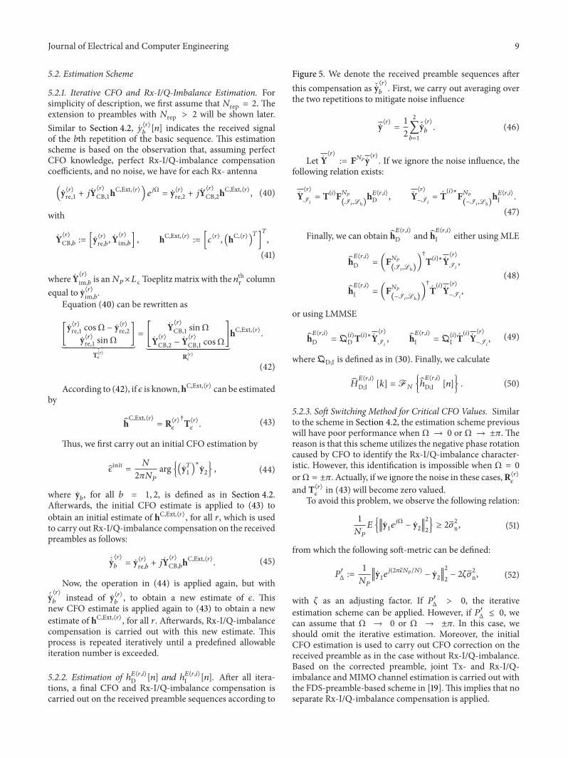
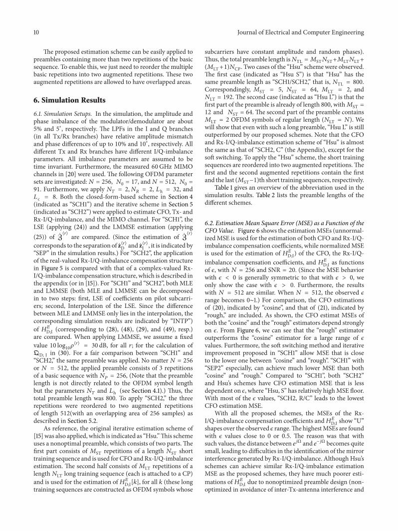
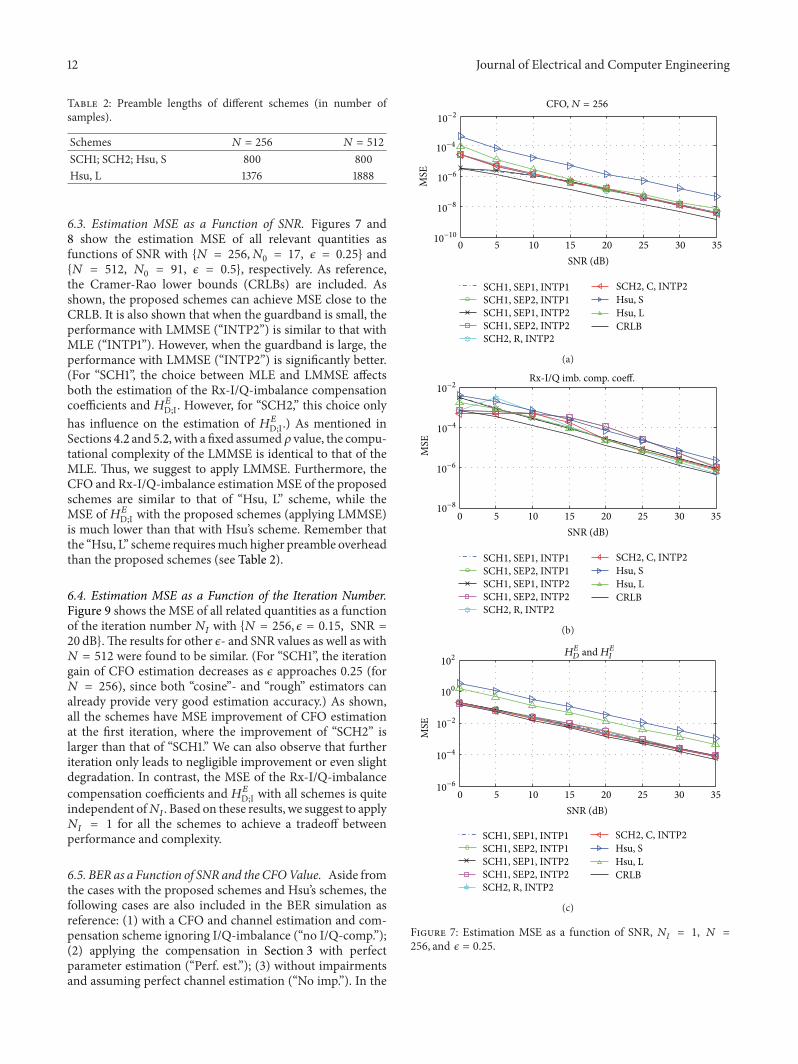
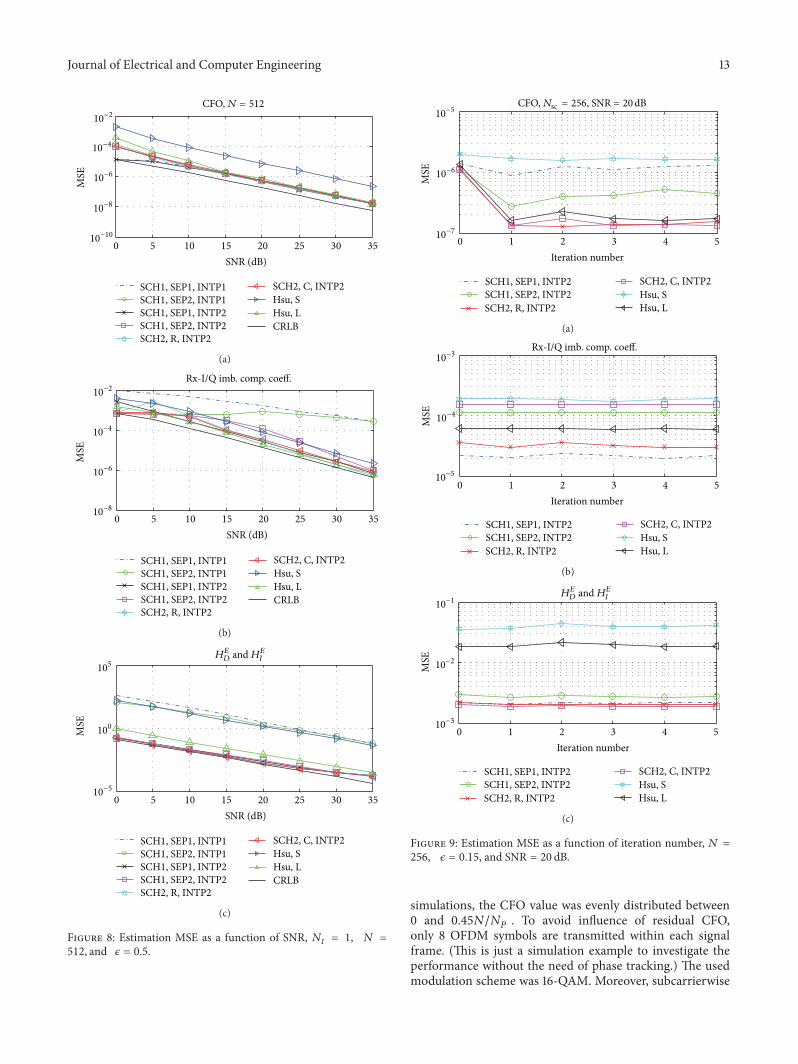
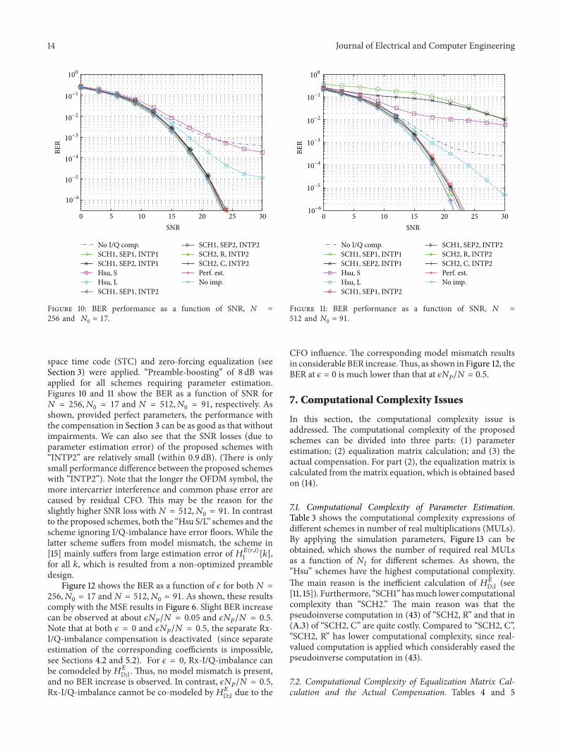
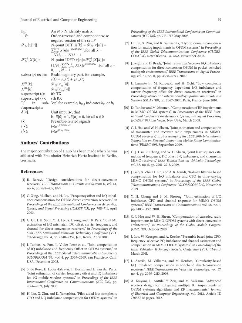

International Journal of
AerospaceEngineeringHindawi Publishing Corporationhttpwwwhindawicom Volume 2014
RoboticsJournal of
Hindawi Publishing Corporationhttpwwwhindawicom Volume 2014
Hindawi Publishing Corporationhttpwwwhindawicom Volume 2014
Active and Passive Electronic Components
Control Scienceand Engineering
Journal of
Hindawi Publishing Corporationhttpwwwhindawicom Volume 2014
International Journal of
RotatingMachinery
Hindawi Publishing Corporationhttpwwwhindawicom Volume 2014
Hindawi Publishing Corporation httpwwwhindawicom
Journal ofEngineeringVolume 2014
Submit your manuscripts athttpwwwhindawicom
VLSI Design
Hindawi Publishing Corporationhttpwwwhindawicom Volume 2014
Hindawi Publishing Corporationhttpwwwhindawicom Volume 2014
Shock and Vibration
Hindawi Publishing Corporationhttpwwwhindawicom Volume 2014
Civil EngineeringAdvances in
Acoustics and VibrationAdvances in
Hindawi Publishing Corporationhttpwwwhindawicom Volume 2014
Hindawi Publishing Corporationhttpwwwhindawicom Volume 2014
Electrical and Computer Engineering
Journal of
Advances inOptoElectronics
Hindawi Publishing Corporation httpwwwhindawicom
Volume 2014
The Scientific World JournalHindawi Publishing Corporation httpwwwhindawicom Volume 2014
SensorsJournal of
Hindawi Publishing Corporationhttpwwwhindawicom Volume 2014
Modelling amp Simulation in EngineeringHindawi Publishing Corporation httpwwwhindawicom Volume 2014
Hindawi Publishing Corporationhttpwwwhindawicom Volume 2014
Chemical EngineeringInternational Journal of Antennas and
Propagation
International Journal of
Hindawi Publishing Corporationhttpwwwhindawicom Volume 2014
Hindawi Publishing Corporationhttpwwwhindawicom Volume 2014
Navigation and Observation
International Journal of
Hindawi Publishing Corporationhttpwwwhindawicom Volume 2014
DistributedSensor Networks
International Journal of