Embed Size (px)
Citation preview
Research ArticleDynamic Characteristics Analysis of the CoupledLateral-Torsional Vibration with Spur Gear System
Shihua Zhou, Zhaohui Ren, Guiqiu Song, and Bangchun Wen
School of Mechanical Engineering & Automation, Northeastern University, Shenyang 110819, China
Correspondence should be addressed to Zhaohui Ren; [email protected]
Received 3 June 2015; Revised 9 September 2015; Accepted 14 September 2015
Academic Editor: Alessandro Corsini
Copyright © 2015 Shihua Zhou et al. This is an open access article distributed under the Creative Commons Attribution License,which permits unrestricted use, distribution, and reproduction in any medium, provided the original work is properly cited.
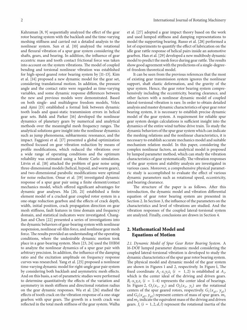
A sixteen-degree-of-freedom (16-DOF) lumped parameter dynamic model taking into account the gravity, eccentricity, bearingclearance, transmission error, and coupled lateral-torsional vibration is established. Based on the dynamical equation, the dynamicbehaviors of the spur gear rotor bearing system are investigated by using Runge-Kutta method. The research focuses on the effectof rotational speed, eccentricity, and bearing clearance and nonlinear response of the coupled multibody dynamics is presentedby vibration waveform, spectrum, and 3D frequency spectrum. The results show that the rotational frequency of the driven gearappears in the driving gear, and the dynamic characteristics of gears have obvious differences due to the effects of the gear assemblyand the coupled lateral-torsional vibration. The bearing has its own resonance frequency, and the effect of the variable stiffnessfrequency of the bearings should be avoided during the system design. The results presented in this paper show an analysis of thecoupled lateral-torsional vibration of the spur gear system. The study may contribute to a further understanding of the dynamiccharacteristics of such a spur gear rotor bearing system.
1. Introduction
It is known that the gear system is widely used in power andmotion transmission device of modern rotating machineries,which are designed for high rotational speed, safety, andefficiency. The excitation and work environment have a veryimportant effect on the entire machine. In order to under-stand dynamic behaviors of gear drives, it is very importantto establish exact coupled lateral-torsional dynamic modelof geared rotor system. In addition, due to the effect ofgear meshing, the gear system presents different vibrationcharacteristics to compare with simplified rotor system.One of the main features of gear model is that it has thecoupled lateral-torsional vibration between the driving gearand driven gear. If the gear drive system does not consider thecoupled lateral-torsional vibration, the calculation accuracyreduces and some important dynamic characteristics maybe lost (torsional excitation may excite the lateral responseand coupled lateral-torsional vibration causes new frequencycomponent). In recent years, many researchers have madea great contribution to study dynamic characteristics of
spur gear systems by, respectively, applying experimentalmethods, numerical simulation, and analytical methods [1–6]. Lin [1, 2] established a torsional vibration model ofgear rotor system and studied the parameter influence ofmeshing force, dynamic load, and tip relief. Raghothamaand Narayanan [3] investigated the periodic motions of anonlinear gear rotor bearing system by the incremental har-monic balance method (IHBM), and the periodic solutionsand subharmonic solutions were obtained. Lund [4] and Iidaet al. [5] proposed a dynamic model with coupled vibrationof gear system, in which the lateral-torsional motion wasconsidered. They provided effective method for dynamicdesign of the transmission system. Kahraman and Singh [6]studied the nonlinear dynamic characteristics of spur gearsystemwith theHBM. In order to further study the nonlinearcharacteristics of gear transmission system, Kahraman andSingh [7] deduced the nonlinear dynamic equation of spurgear rotor system and the influences of various parameterswere studied and they analyzed the nonlinear dynamicresponse of spur gear system with HBM and Runge-Kuttamethod. Due to the effect of time-varying mesh stiffness,
Hindawi Publishing CorporationInternational Journal of Rotating MachineryVolume 2015, Article ID 371408, 14 pageshttp://dx.doi.org/10.1155/2015/371408
2 International Journal of Rotating Machinery
Kahraman [8, 9] sequentially analyzed the effect of the gearrotor bearing system with the backlash and the time-varyingmeshing stiffness and carried out a detailed analysis to thenonlinear system. Sun et al. [10] analyzed the rotationaland flexural vibration of a spur gear system considering theshafts, gears, and bearing. In addition, the influence of geareccentric mass and tooth contact frictional force was takeninto account on the system vibrations. The model of coupledbending and torsional nonlinear vibration was establishedfor high-speed geared rotor bearing system by [11–13]. Kimet al. [14] proposed a new dynamic model for the gear set,considering translational motion. In addition, the pressureangle and the contact ratio were regarded as time-varyingvariables, and some dynamic response differences betweenthe new and previous models were demonstrated. Basedon both single- and multidegree freedom models, Velexand Ajmi [15] established a formal link between dynamictooth loads and quasi-static transmission errors in helicalgear sets. Bahk and Parker [16] developed the nonlineardynamics of planetary gears by numerical and analyticalmethods over the meaningful mesh frequency ranges. Theanalytical solutions gave insight into the nonlinear dynamicssuch as jump phenomena, subharmonic resonance, and theimpact. Faggioni et al. [17] presented a global optimizationmethod focused on gear vibration reduction by means ofprofile modifications, which reduced the vibrations overa wide range of operating conditions and the optimumreliability was estimated using a Monte Carlo simulation.Litvin et al. [18] attacked the problem of gear noise usingthree-dimensional models (helical, hypoid, and worm gears),and two-dimensional parabolic modifications were optimalfor noise reduction. Omar et al. [19] investigated dynamicresponse of a spur gear pair using a finite element/contactmechanics model, which offered significant advantages fordynamic gear analyses. Ma [20, 21] established a finiteelement model of a cracked gear coupled rotor system in aone-stage reduction gearbox and the effects of crack depth,width, initial position, crack propagation direction on gearmesh stiffness, fault features in time domain and frequencydomain, and statistical indicators were investigated. Chang-Jian and Chen [22] presented a series of investigations intothe dynamic behaviors of gear-bearing systemwith nonlinearsuspension, nonlinear oil-film force, and nonlinear gearmeshforce.The results provided an understanding of the operatingconditions, where the undesirable dynamic motion tookplace in a gear-bearing system. Shen [23, 24] used the IHBMto analyze the nonlinear dynamics of a spur gear pair witharbitrary precision. In addition, the influence of the dampingratio and the excitation amplitude on frequency responsecurves was researched. Yang et al. [25] proposed a nonlineartime-varying dynamicmodel for right-angle gear pair systemby considering both backlash and asymmetric mesh effects.And on this basis, a set of parametric studies were performedto determine quantitatively the effects of the variation andasymmetry in mesh stiffness and directional rotation radiuson the gear dynamic responses. Wu et al. [26] studied theeffects of tooth crack on the vibration response of a one-stagegearbox with spur gears. The growth in a tooth crack wasreflected in the total mesh stiffness of the gear system. Walha
et al. [27] adopted a gear impact theory based on the workand used lumped stiffness and damping representations tomodel the supporting bearing. Russo et al. [28] performed alot of experiments to quantify the effect of lubrication on theidle gear rattle response of helical pairs inside an automotivegearbox. Han et al. [29] developed a newmultibody dynamicmodel to predict themesh force during gear rattle.The resultsshow good agreementwith the predictions of a single-degree-of-freedom theoretical model.
It can be seen from the previous references that the mostof existing gear transmission system ignores the nonlinearsupport, shaft elastic deformation, and the gravity of thespur system. Hence, the gear rotor bearing system compre-hensively including the eccentricity, bearing clearance, andother factors with a nonlinear dynamic model of coupledlateral-torsional vibration is rare. In order to obtain detailedanalysis andmaster dynamic characteristics of spur gear rotorbearing system, it is necessary to establish precise dynamicmodel of the gear system. A requirement for reliable spurgear system design calculations is sufficient insight into thedynamics of the entire wind turbine drive train. To study thedynamic behaviors of the spur gear systemwhich can indicatethe meshing relations and the nonlinear characteristics, it isnecessary to establish accurate mechanics model and suitablemechanism relation model. In this paper, considering thecomplex nonlinear factors, an analytical model is proposedby lumped parameter method, which can study the vibrationcharacteristics of gear systematically.The vibration responsesof the gear system and stability analysis are investigated invarious cases. Moreover, a comprehensive physical paramet-ric study is accomplished to evaluate the effect of variousdynamic parameters such as rotational speed, eccentricity,and bearing clearance.
The structure of the paper is as follows. After thisintroduction, the dynamic model and vibration differentialequation of gear rotor bearing system are presented inSection 2. In Section 3, the influence of the parameters on thecharacteristics and level of vibrations are studied. And thevibration responses of the coupled lateral-torsional systemare analyzed. Finally, conclusions are drawn in Section 4.
2. Mathematical Model andEquations of Motion
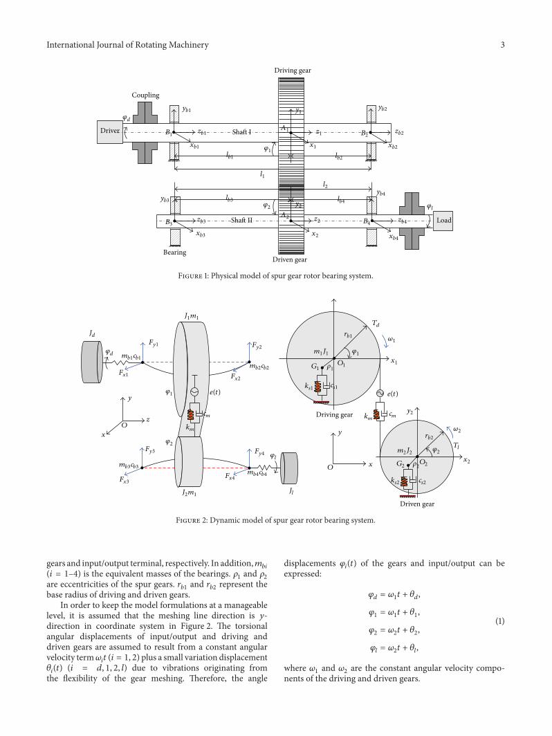
2.1. Dynamic Model of Spur Gear Rotor Bearing System. A16-DOF lumped parameter dynamic model considering thecoupled lateral-torsional vibration is developed to study thedynamic characteristics of the spur gear rotor bearing system.The physical model and dynamic model of the gear systemare shown in Figures 1 and 2, respectively. In Figure 1, Thefixed coordinate 𝐴
𝑖-𝑥𝑖𝑦𝑖𝑧𝑖(𝑖 = 1, 2) is established at 𝐴
𝑖,
which is the center ideal of the driving and driven gears.𝐵𝑖-𝑥𝑖𝑦𝑖𝑧𝑖(𝑖 = 1–4) represents the center ideal of bearings.
In Figure 2, 𝑂1(𝑥1, 𝑦1) and 𝑂
2(𝑥2, 𝑦2) are the rotational
centers of the spur geared rotors, respectively. 𝐺1(𝑥𝑔1, 𝑦𝑔1)
and 𝐺2(𝑥𝑔2, 𝑦𝑔2) represent centers of mass of spur gears. 𝑚
1
and𝑚2indicate the equivalentmass of the driving and driven
gears. 𝐽𝑖(𝑖 = 1, 2, 𝑑, 𝑙) represent the rotational inertia of the
International Journal of Rotating Machinery 3
Driving gear
Driven gear
Driver
Load
Shaft I
Shaft II
Bearing
Coupling
A1
A2
B1 B2
B3 B4
𝜑d
yb1
xb1
zb1
yb2
xb2
zb2
yb3
xb3
zb3
yb4
xb4
zb4
lb1 lb2
lb3 lb4
l1l2
y1
x1
z1
y2
x2
z2
𝜑l
𝜑1
𝜑2
Figure 1: Physical model of spur gear rotor bearing system.
Driving gear
Driven gear
y2
x1
x2𝜑l
Jd
𝜑d mb1cb1
Fy1
Fx1
J1m1
𝜑1
𝜑1
x
x
y
y
z
O
mb2cb2
Fy2
Fx2
J2m1
𝜑2𝜑2
mb3cb3
Fy3
Fx3
mb4cb4
Fy4
Fx4
e(t) e(t)
cm cm
km
km
Td
𝜔1rb1
G1
ks1 cs1
𝜌1
Tl
𝜔2rb2
m2J2
G2
ks2 cs2
𝜌2
m1J1
Jl
O1
O2
O
Figure 2: Dynamic model of spur gear rotor bearing system.
gears and input/output terminal, respectively. In addition,𝑚𝑏𝑖
(𝑖 = 1–4) is the equivalent masses of the bearings. 𝜌1and 𝜌2
are eccentricities of the spur gears. 𝑟𝑏1
and 𝑟𝑏2
represent thebase radius of driving and driven gears.
In order to keep the model formulations at a manageablelevel, it is assumed that the meshing line direction is 𝑦-direction in coordinate system in Figure 2. The torsionalangular displacements of input/output and driving anddriven gears are assumed to result from a constant angularvelocity term𝜔
𝑖𝑡 (𝑖 = 1, 2) plus a small variation displacement
𝜃𝑖(𝑡) (𝑖 = 𝑑, 1, 2, 𝑙) due to vibrations originating from
the flexibility of the gear meshing. Therefore, the angle
displacements 𝜑𝑖(𝑡) of the gears and input/output can be
expressed:
𝜑𝑑= 𝜔1𝑡 + 𝜃𝑑,
𝜑1= 𝜔1𝑡 + 𝜃1,
𝜑2= 𝜔2𝑡 + 𝜃2,
𝜑𝑙= 𝜔2𝑡 + 𝜃𝑙,
(1)
where 𝜔1and 𝜔
2are the constant angular velocity compo-
nents of the driving and driven gears.
4 International Journal of Rotating Machinery
Inner ring Outer ring
Ball𝜔oj
y2𝜋/Nb
𝜑j
𝜔j
R
O1
O2r
x
𝜔bt
db
d di dodmD
Figure 3: Rolling bearing model.
The relationship between 𝐺1and 𝐺
2and 𝑂
1and 𝑂
2is
expressed as
𝑥𝑔1
= 𝑥1+ 𝜌1cos (−𝜑
1) ,
𝑦𝑔1
= 𝑦1+ 𝜌1sin (−𝜑
1) ,
𝑥𝑔2
= 𝑥2+ 𝜌2cos𝜑2,
𝑦𝑔2
= 𝑦2+ 𝜌2sin𝜑2.
(2)
In order to ensure the contact of teeth surface onmeshingperformance, it is assumed that the relative deformation ofgear is completely changed into elastic deformation on teethsurface alongwith themesh line direction.Themeshing gearsare connected through the spring and damping. Therefore,the comprehensive deformation between the driving anddriven gears along the mesh line direction is expressed as
𝛿 = 𝑦1− 𝑦2+ 𝜃1𝑟𝑏1
− 𝜃2𝑟𝑏2
+ 𝜌1sin (−𝜑
1) − 𝜌2sin𝜑2
− 𝑒 (𝑡) .
(3)
The dynamic meshing force along the line-of-action canbe described as
𝐹𝑚
= 𝑐𝑚
𝛿 + 𝑘𝑚𝛿, (4)
where 𝑘𝑚and 𝑐𝑚represent the average meshing stiffness and
damping. 𝑒(𝑡) indicates the static transmission error, whichcan be described as follows:
𝑒 (𝑡) = 𝑒𝑚+ 𝑒𝑟sin (𝜔
𝑒𝑡 + 𝜑𝑒) ; (5)
here, 𝑒𝑚and 𝑒𝑟stand for the mean and fluctuation; 𝜔
𝑒is the
gear meshing frequency, and 𝜔𝑒= 2𝜋𝑛
1𝑧1/60 = 2𝜋𝑛
2𝑧2/60;
𝜑𝑒is the initial phase. 𝑛
1and 𝑛2are rotational speed of gears.
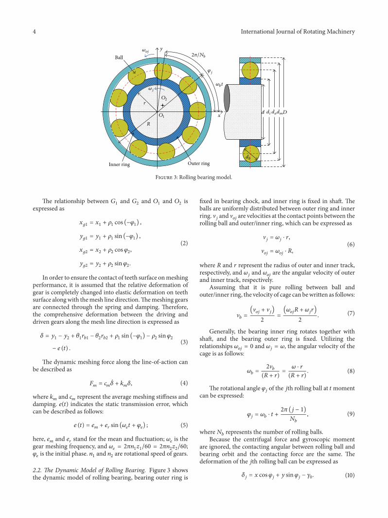
2.2. The Dynamic Model of Rolling Bearing. Figure 3 showsthe dynamic model of rolling bearing, bearing outer ring is
fixed in bearing chock, and inner ring is fixed in shaft. Theballs are uniformly distributed between outer ring and innerring. V
𝑗and V𝑜𝑗are velocities at the contact points between the
rolling ball and outer/inner ring, which can be expressed as
V𝑗= 𝜔𝑗⋅ 𝑟,
V𝑜𝑗
= 𝜔𝑜𝑗⋅ 𝑅,
(6)
where 𝑅 and 𝑟 represent the radius of outer and inner track,respectively, and 𝜔
𝑗and 𝜔
𝑜𝑗are the angular velocity of outer
and inner track, respectively.Assuming that it is pure rolling between ball and
outer/inner ring, the velocity of cage can bewritten as follows:
V𝑏=
(V𝑜𝑗+ V𝑗)
2=
(𝜔𝑜𝑗𝑅 + 𝜔
𝑗𝑟)
2. (7)
Generally, the bearing inner ring rotates together withshaft, and the bearing outer ring is fixed. Utilizing therelationships 𝜔
𝑜𝑗= 0 and 𝜔
𝑗= 𝜔, the angular velocity of the
cage is as follows:
𝜔𝑏=
2V𝑏
(𝑅 + 𝑟)=
𝜔 ⋅ 𝑟
(𝑅 + 𝑟). (8)
The rotational angle 𝜑𝑗of the 𝑗th rolling ball at 𝑡moment
can be expressed:
𝜑𝑗= 𝜔𝑏⋅ 𝑡 +
2𝜋 (𝑗 − 1)
𝑁𝑏
, (9)
where𝑁𝑏represents the number of rolling balls.
Because the centrifugal force and gyroscopic momentare ignored, the contacting angular between rolling ball andbearing orbit and the contacting force are the same. Thedeformation of the 𝑗th rolling ball can be expressed as
𝛿𝑗= 𝑥 cos𝜑
𝑗+ 𝑦 sin𝜑
𝑗− 𝛾0. (10)
International Journal of Rotating Machinery 5
According to nonlinear Hertz contact theory, the contactforce between the 𝑗th rolling ball and the bearing orbits is𝑓𝑏𝑗; at the same time, the normal stress can be only generated
between the rolling ball and the bearing orbits when 𝛿𝑗is
greater than zero. So the force 𝑓𝑗can be expressed by [30]
𝑓𝑗= 𝑘𝑏(𝛿𝑗)3/2
= 𝑘𝑏(𝑥 cos𝜑
𝑗+ 𝑦 sin𝜑
𝑗− 𝛾0)3/2
⋅ 𝐻 (𝑥 cos𝜑𝑗+ 𝑦 sin𝜑
𝑗− 𝛾0) ,
(11)
where 𝑘𝑏is Hertz contact stiffness and 𝐻(𝑥) represents
Heaviside function and can be written as follows:
𝐻(𝑥){
{
{
1 if 𝑥 > 0
0 if 𝑥 ≤ 0.
(12)
So the bearing forces (𝐹𝑥and 𝐹
𝑦) in 𝑥-direction and 𝑦-
direction can be described as follows:
𝐹 =
𝑁𝑏
∑
𝑗=1
𝑓𝑗=
𝑁𝑏
∑
𝑗=1
[𝑘𝑏(𝑥 cos𝜑
𝑗+ 𝑦 sin𝜑
𝑗− 𝛾0)3/2
⋅ 𝐻 (𝑥 cos𝜑𝑗+ 𝑦 sin𝜑
𝑗− 𝛾0) cos𝜑
𝑗] ,
𝐹𝑥=
𝑁𝑏
∑
𝑗=1
𝑓𝑥𝑗
= 𝐹 cos𝜑𝑗,
𝐹𝑦=
𝑁𝑏
∑
𝑗=1
𝑓𝑦𝑗
= 𝐹 sin𝜑𝑗.
(13)
2.3. Equations of Motion. The model in this paper takesthe average meshing stiffness of the spur gears withoutconsideration of meshing backlash and friction.Themeshingforce 𝐹
𝑚in direction of contacting line on the tooth surface
acts on the center of tooth width. A displacement vectorof spur gear system can be defined from the pressure linecoordinate system, as shown in Figure 2. The generalizeddeformation vector can be expressed as follows:
[𝜃𝑑 𝑥1
𝑦1
𝜃1
𝑥2
𝑦2
𝜃2
𝑥𝑏1
𝑦𝑏1
𝑥𝑏2
𝑦𝑏2
𝑥𝑏3
𝑦𝑏3
𝑥𝑏4
𝑦𝑏4
𝜃𝑙]⊤, (14)
where 𝜃𝑑, 𝜃𝑙, 𝜃1, and 𝜃
2represent the torsional vibration
angular displacement of input terminal, output terminal,driving gear, and driven gear, respectively. 𝑥
𝑖and 𝑦
𝑖(𝑖 =
1, 2) are the vibration displacement in 𝑥-direction and 𝑦-direction of driving and driven gears. 𝑥
𝑏𝑖and 𝑦
𝑏𝑖(𝑖 = 1–4)
are the vibration displacement of bearings in 𝑥-direction and𝑦-direction, respectively. Considering the unbalanced force,meshing torque, and input/output torque, the kinetic energy𝑇, the potential energy 𝑈, and the dissipation function 𝑅 areestablished of the system. According to Lagrange’s equation,the differential equations of the gear system can be expressedby following equations:
𝐽𝑑
𝜃𝑑+ 𝑐𝑡1( 𝜃𝑑− 𝜃1) + 𝑘𝑡1(𝜃𝑑− 𝜃1) = 𝑇𝑑,
𝑚1��1+ 𝑐𝑠1(��1− 𝜉2��𝑏1
− 𝜉1��𝑏2)
+ 𝑘𝑠1(𝑥1− 𝜉2𝑥𝑏1
− 𝜉1𝑥𝑏2) = 𝑚
1𝜌1
𝜃1sin (𝜔
1𝑡 + 𝜃1)
+ 𝑚1𝜌1(𝜔1+ 𝜃1)2
cos (𝜔1𝑡 + 𝜃1) ,
𝑚1
𝑦1+ 𝑐𝑠1( 𝑦1− 𝜉2
𝑦𝑏1
− 𝜉1
𝑦𝑏2)
+ 𝑘𝑠1(𝑦1− 𝜉2𝑦𝑏1
− 𝜉1𝑦𝑏2) = 𝑚
1𝜌1
𝜃1cos (𝜔
1𝑡 + 𝜃1)
− 𝑚1𝜌1(𝜔1+ 𝜃1)2
sin (𝜔1𝑡 + 𝜃1) − 𝐹𝑚− 𝑚1𝑔,
(𝐽1+ 𝑚1𝜌2
1) 𝜃1+ 𝑐𝑡1( 𝜃1− 𝜃𝑑) + 𝑘𝑡1(𝜃1− 𝜃𝑑)
= 𝑚1𝜌1sin (𝜔
1𝑡 + 𝜃1) ��1+ 𝑚1𝜌1cos (𝜔
1𝑡 + 𝜃1) 𝑦1
− 𝐹𝑚𝑟𝑏1,
𝑚2��2+ 𝑐𝑠2(��2− 𝜉4��𝑏3
− 𝜉3��𝑏4)
+ 𝑘𝑠2(𝑥2− 𝜉4𝑥𝑏3
− 𝜉3𝑥𝑏4) = 𝑚
2𝜌2
𝜃2sin (𝜔
2𝑡 + 𝜃2)
+ 𝑚2𝜌2(𝜔2+ 𝜃2)2
cos (𝜔2𝑡 + 𝜃2) ,
𝑚2
𝑦2+ 𝑐𝑠2( 𝑦2− 𝜉4
𝑦𝑏3
− 𝜉3
𝑦𝑏4)
+ 𝑘𝑠2(𝑦2− 𝜉4𝑦𝑏3
− 𝜉3𝑦𝑏4)
= −𝑚2𝜌2
𝜃2cos (𝜔
2𝑡 + 𝜃2)
+ 𝑚2𝜌2(𝜔2+ 𝜃2)2
sin (𝜔2𝑡 + 𝜃2) + 𝐹𝑚− 𝑚2𝑔,
(𝐽2+ 𝑚2𝜌2
2) 𝜃2+ 𝑐𝑡2( 𝜃2− 𝜃𝑙) + 𝑘𝑡2(𝜃2− 𝜃𝑙)
= 𝑚2𝜌2sin (𝜔
2𝑡 + 𝜃2) ��2− 𝑚2𝜌2cos (𝜔
2𝑡 + 𝜃2) 𝑦2
+ 𝐹𝑚𝑟𝑏2,
𝑚𝑏1��𝑏1
+ 𝑐𝑠1𝜉2(−��1+ 𝜉2��𝑏1
+ 𝜉1��𝑏2) + 𝑐𝑏𝑥1
��𝑏1
+ 𝑘𝑠1𝜉2(−𝑥1+ 𝜉2𝑥𝑏1
+ 𝜉1𝑥𝑏2) = 𝐹𝑥1,
𝑚𝑏1
𝑦𝑏1
+ 𝑐𝑠1𝜉2(− 𝑦1+ 𝜉2
𝑦𝑏1
+ 𝜉1
𝑦𝑏2) + 𝑐𝑏𝑦1
𝑦𝑏1
+ 𝑘𝑠1𝜉2(−𝑦1+ 𝜉2𝑦𝑏1
+ 𝜉1𝑦𝑏2) = 𝐹𝑦1
− 𝑚𝑏1𝑔,
6 International Journal of Rotating Machinery
𝑚𝑏2��𝑏2
+ 𝑐𝑠1𝜉1(−��1+ 𝜉2��𝑏1
+ 𝜉1��𝑏2) + 𝑐𝑏𝑥2
��𝑏2
+ 𝑘𝑠1𝜉1(−𝑥1+ 𝜉2𝑥𝑏1
+ 𝜉1𝑥𝑏2) = 𝐹𝑥2,
𝑚𝑏2
𝑦𝑏2
+ 𝑐𝑠1𝜉1(− 𝑦1+ 𝜉2
𝑦𝑏1
+ 𝜉1
𝑦𝑏2) + 𝑐𝑏𝑦2
𝑦𝑏2
+ 𝑘𝑠1𝜉1(−𝑦1+ 𝜉2𝑦𝑏1
+ 𝜉1𝑦𝑏2) = 𝐹𝑦2
− 𝑚𝑏2𝑔,
𝑚𝑏3��𝑏3
+ 𝑐𝑠2𝜉4(−��2+ 𝜉4��𝑏3
+ 𝜉3��𝑏4) + 𝑐𝑏𝑥3
��𝑏3
+ 𝑘𝑠2𝜉4(−𝑥2+ 𝜉4𝑥𝑏3
+ 𝜉3𝑥𝑏4) = 𝐹𝑥3,
𝑚𝑏3
𝑦𝑏3
+ 𝑐𝑠2𝜉4(− 𝑦2+ 𝜉4
𝑦𝑏3
+ 𝜉3
𝑦𝑏4) + 𝑐𝑏𝑦3
𝑦𝑏3
+ 𝑘𝑠2𝜉4(−𝑦2+ 𝜉4𝑦𝑏3
+ 𝜉3𝑦𝑏4) = 𝐹𝑦3
− 𝑚𝑏3𝑔,
𝑚𝑏4��𝑏4
+ 𝑐𝑠2𝜉3(−��2+ 𝜉4��𝑏3
+ 𝜉3��𝑏4) + 𝑐𝑏𝑥4
��𝑏4
+ 𝑘𝑠2𝜉3(−𝑥2+ 𝜉4𝑥𝑏3
+ 𝜉3𝑥𝑏4) = 𝐹𝑥4,
𝑚𝑏4
𝑦𝑏4
+ 𝑐𝑠2𝜉3(− 𝑦2+ 𝜉4
𝑦𝑏3
+ 𝜉3
𝑦𝑏4) + 𝑐𝑏𝑦4
𝑦𝑏4
+ 𝑘𝑠2𝜉3(−𝑦2+ 𝜉4𝑦𝑏3
+ 𝜉3𝑦𝑏4) = 𝐹𝑦4
− 𝑚𝑏4𝑔,
𝐽𝑙𝜃𝑙+ 𝑐𝑡2( 𝜃𝑙− 𝜃2) + 𝑘𝑡2(𝜃𝑙− 𝜃2) = −𝑇
𝑙,
(15)
where 𝑘𝑠𝑖and 𝑐𝑠𝑖(𝑖 = 1, 2) are the lateral stiffness and damping
of shafts. 𝑘𝑡𝑖and 𝑐𝑡𝑖(𝑖 = 1, 2) represent the torsional stiffness
and damping of shafts. 𝑐𝑏𝑥𝑖
and 𝑐𝑏𝑦𝑖
(𝑖 = 1–4) are the bearingdamping in 𝑥-direction and 𝑦-direction;𝐹
𝑥𝑖and𝐹𝑦𝑖(𝑖 = 1–4)
indicate the bearing force.
3. The Coupled Lateral-TorsionalVibration of Gear System
In this paper, the dynamical equations presented in (15)for the spur gear rotor bearing system with the gravity,input/output torque, transmission error, and eccentricity andcoupled lateral-torsional vibration are investigated using theRunge-Kutta method. The key parameters are investigated toobtain a basic understanding of the dynamic behaviors of thespur gear system. Table 1 summarizes the geometrical andphysical parameters of spur gear system. Let rotational speed,eccentricity, and bearing clearance be control parameters inthe following analysis.
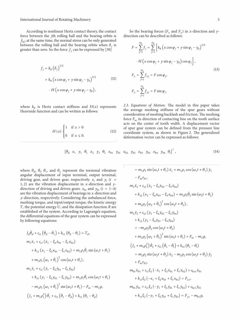
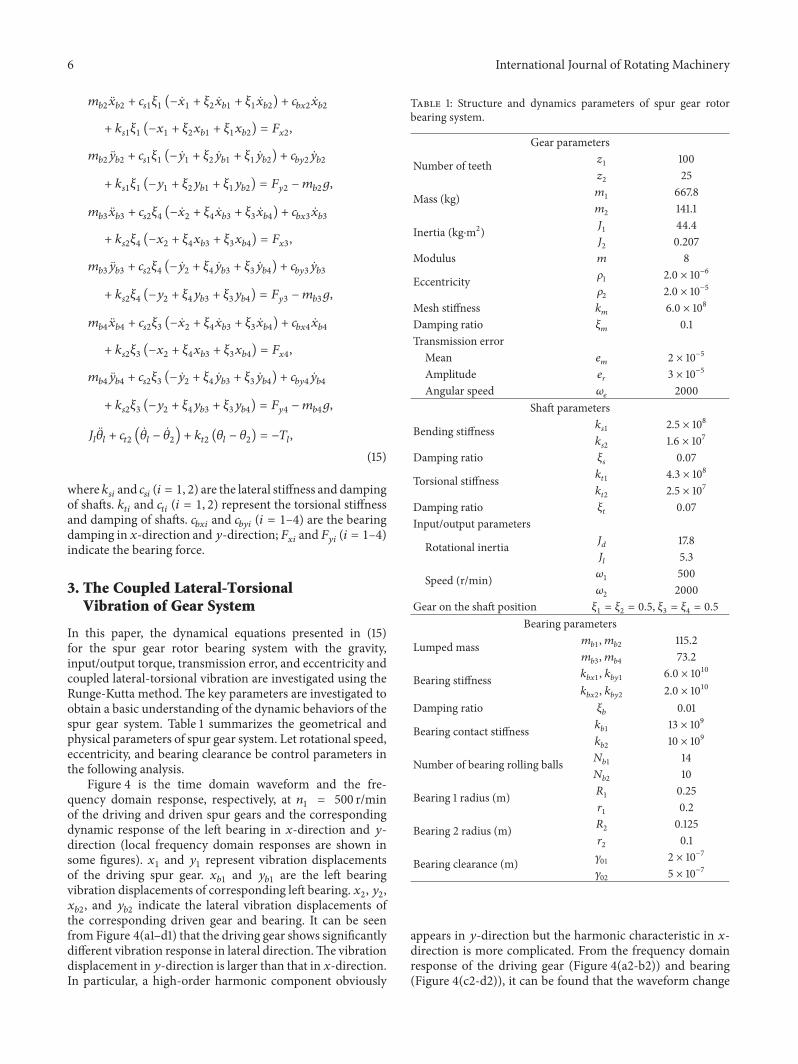
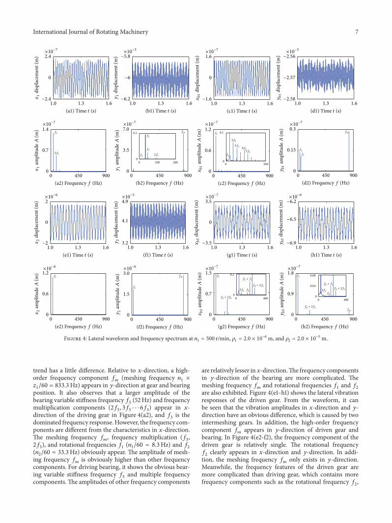
Figure 4 is the time domain waveform and the fre-quency domain response, respectively, at 𝑛
1= 500 r/min
of the driving and driven spur gears and the correspondingdynamic response of the left bearing in 𝑥-direction and 𝑦-direction (local frequency domain responses are shown insome figures). 𝑥
1and 𝑦
1represent vibration displacements
of the driving spur gear. 𝑥𝑏1
and 𝑦𝑏1
are the left bearingvibration displacements of corresponding left bearing. 𝑥
2, 𝑦2,
𝑥𝑏2, and 𝑦
𝑏2indicate the lateral vibration displacements of
the corresponding driven gear and bearing. It can be seenfrom Figure 4(a1–d1) that the driving gear shows significantlydifferent vibration response in lateral direction.The vibrationdisplacement in 𝑦-direction is larger than that in 𝑥-direction.In particular, a high-order harmonic component obviously
Table 1: Structure and dynamics parameters of spur gear rotorbearing system.
Gear parameters
Number of teeth 𝑧1
100𝑧2
25
Mass (kg) 𝑚1
667.8𝑚2
141.1
Inertia (kg⋅m2) 𝐽1
44.4𝐽2
0.207Modulus 𝑚 8
Eccentricity 𝜌1
2.0 × 10⁻⁶
𝜌2
2.0 × 10⁻⁵
Mesh stiffness 𝑘𝑚
6.0 × 10⁸
Damping ratio 𝜉𝑚
0.1Transmission errorMean 𝑒
𝑚2 × 10⁻⁵
Amplitude 𝑒𝑟
3 × 10⁻⁵
Angular speed 𝜔𝑒
2000Shaft parameters
Bending stiffness 𝑘𝑠1
2.5 × 10⁸
𝑘𝑠2
1.6 × 10⁷
Damping ratio 𝜉𝑠
0.07
Torsional stiffness 𝑘𝑡1
4.3 × 10⁸
𝑘𝑡2
2.5 × 10⁷
Damping ratio 𝜉𝑡
0.07Input/output parameters
Rotational inertia 𝐽𝑑
17.8𝐽𝑙
5.3
Speed (r/min) 𝜔1
500𝜔2
2000Gear on the shaft position 𝜉
1= 𝜉2= 0.5, 𝜉
3= 𝜉4= 0.5
Bearing parameters
Lumped mass 𝑚𝑏1,𝑚𝑏2
115.2𝑚𝑏3,𝑚𝑏4
73.2
Bearing stiffness 𝑘𝑏𝑥1
, 𝑘𝑏𝑦1
6.0 × 10¹⁰
𝑘𝑏𝑥2
, 𝑘𝑏𝑦2
2.0 × 10¹⁰
Damping ratio 𝜉𝑏
0.01
Bearing contact stiffness 𝑘𝑏1
13 × 109
𝑘𝑏2
10 × 109
Number of bearing rolling balls 𝑁𝑏1
14𝑁𝑏2
10
Bearing 1 radius (m) 𝑅1
0.25𝑟1
0.2
Bearing 2 radius (m) 𝑅2
0.125𝑟2
0.1
Bearing clearance (m) 𝛾01
2 × 10⁻⁷
𝛾02
5 × 10⁻⁷
appears in 𝑦-direction but the harmonic characteristic in 𝑥-direction is more complicated. From the frequency domainresponse of the driving gear (Figure 4(a2-b2)) and bearing(Figure 4(c2-d2)), it can be found that the waveform change
International Journal of Rotating Machinery 7
×10−7
×10−7
×10−7
×10−7 ×10−7
×10−7 ×10−7 ×10−7
×10−7
×10−6 ×10−6
×10−6×10−6
×10−5
×10−5
×10−5
0
0.5
0 100 200 0
0.1
0
0.2
0 4000
0.08
0.04
0 400
0 500
f1 f1
f2
f2
f2f2
f2
f2
f3
f3
f3
f3
f4
f4
fmfm
fm
fm
f4 + 2f2
f4 + 2f2
f4 + f2
2f2 2f2
f4 + 3f2f4 + f2
f4 + 3f2
3f34f3
5f32f3 2f3
2f3
−2.4
0
2.4
x1
disp
lace
men
t (m
)
1.3 1.61.0
(a1) Time t (s)
−6.2
−6
−5.8
y1
disp
lace
men
t (m
)
1.3 1.61.0
(b1) Time t (s)
−1.6
0
1.6
xb1
disp
lace
men
t (m
)
1.3 1.61.0
(c1) Time t (s)
−2.58
−2.57
−2.56
yb1
disp
lace
men
t (m
)
1.3 1.61.0
(d1) Time t (s)
0
0.15
0.3
yb1
ampl
itude
A(m
)
0 900450
(d2) Frequency f (Hz)0 900450
(c2) Frequency f (Hz)
0
0.6
1.2
xb1
ampl
itude
A(m
)
0 900450
(b2) Frequency f (Hz)
0
3.5
7.0
y1
ampl
itude
A(m
)
0 900450
(a2) Frequency f (Hz)
0
0.7
1.4
x1
ampl
itude
A(m
)
−2
0
2
x2
disp
lace
men
t (m
)
1.3 1.61.0
(e1) Time t (s)
3.2
4.1
4.9
y2
disp
lace
men
t (m
)
1.3 1.61.0
(f1) Time t (s)
−3.5
0
3.5xb3
disp
lace
men
t (m
)
1.3 1.61.0
(g1) Time t (s)
−6.9
−6.5
−6.2
yb3
disp
lace
men
t (m
)
1.3 1.61.0
(h1) Time t (s)
0
0.9
1.8
yb3
ampl
itude
A(m
)
0 900450
(h2) Frequency f (Hz)0 900450
(g2) Frequency f (Hz)
0
0.7
1.5
xb3
ampl
itude
A(m
)
0 900450
(f2) Frequency f (Hz)
0
1.5
3.0
y2
ampl
itude
A(m
)
0 900450
(e2) Frequency f (Hz)
0
0.6
1.2
x2
ampl
itude
A(m
)
Figure 4: Lateral waveform and frequency spectrum at 𝑛1= 500 r/min, 𝜌
1= 2.0 × 10⁻⁶m, and 𝜌
2= 2.0 × 10⁻⁵m.
trend has a little difference. Relative to 𝑥-direction, a high-order frequency component 𝑓
𝑚(meshing frequency 𝑛
1×
𝑧1/60 = 833.3Hz) appears in 𝑦-direction at gear and bearing
position. It also observes that a larger amplitude of thebearing variable stiffness frequency 𝑓
3(52Hz) and frequency
multiplication components (2𝑓3, 3𝑓3⋅ ⋅ ⋅ 6𝑓3) appear in 𝑥-
direction of the driving gear in Figure 4(a2), and 𝑓3is the
dominated frequency response.However, the frequency com-ponents are different from the characteristics in 𝑥-direction.The meshing frequency 𝑓
𝑚, frequency multiplication (𝑓
3,
2𝑓3), and rotational frequencies 𝑓
1(𝑛1/60 = 8.3Hz) and 𝑓
2
(𝑛2/60 = 33.3Hz) obviously appear. The amplitude of mesh-
ing frequency 𝑓𝑚is obviously higher than other frequency
components. For driving bearing, it shows the obvious bear-ing variable stiffness frequency 𝑓
3and multiple frequency
components.The amplitudes of other frequency components
are relatively lesser in𝑥-direction.The frequency componentsin 𝑦-direction of the bearing are more complicated. Themeshing frequency 𝑓
𝑚and rotational frequencies 𝑓
1and 𝑓
2
are also exhibited. Figure 4(e1–h1) shows the lateral vibrationresponses of the driven gear. From the waveform, it canbe seen that the vibration amplitudes in 𝑥-direction and 𝑦-direction have an obvious difference, which is caused by twointermeshing gears. In addition, the high-order frequencycomponent 𝑓
𝑚appears in 𝑦-direction of driven gear and
bearing. In Figure 4(e2-f2), the frequency component of thedriven gear is relatively single. The rotational frequency𝑓2clearly appears in 𝑥-direction and 𝑦-direction. In addi-
tion, the meshing frequency 𝑓𝑚only exists in 𝑦-direction.
Meanwhile, the frequency features of the driven gear aremore complicated than driving gear, which contains morefrequency components such as the rotational frequency 𝑓
2,
8 International Journal of Rotating Machinery
bearing variable stiffness frequency 𝑓4(147.4Hz), frequency
multiplication, and frequency combination components (𝑓2+
𝑓4, 2𝑓2+ 𝑓4,. . .).
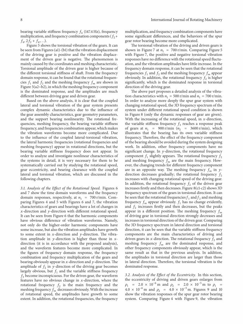
Figure 5 shows the torsional vibration of the gears. It canbe seen fromFigures (a1)-(b1) that the vibration displacementof the driving gear is positive and the vibration displace-ment of the driven gear is negative. The phenomenon ismainly caused by the coordinates andmeshing characteristic.Torsional amplitude of the driven gear is higher because ofthe different torsional stiffness of shaft. From the frequencydomain response, it can be found that the rotational frequen-cies 𝑓
1and 𝑓
2and the meshing frequency 𝑓
𝑚are shown in
Figure 5(a2∼b2), inwhich themeshing frequency componentis the dominated response, and the amplitudes are muchdifferent between driving gear and driven gear.
Based on the above analysis, it is clear that the coupledlateral and torsional vibration of the gear system presentscomplex dynamic characteristics due to the influence ofthe gear assembly characteristics, gear geometry parameters,and the support bearing nonlinearity. The rotational fre-quencies, meshing frequency, the bearing variable stiffnessfrequency, and frequencies combination appear, whichmakesthe vibration waveforms become more complicated. Dueto the influence of the coupled lateral-torsional vibration,the lateral harmonic frequencies (rotational frequencies andmeshing frequency) appear in rotational directions, but thebearing variable stiffness frequency does not appear. Inorder to analyze and investigate nonlinear characteristics ofthe systems in detail, it is very necessary for them to besystematically carried out by studying the rotational speed,gear eccentricity, and bearing clearance with the coupledlateral and torsional vibration, which are discussed in thefollowing chapters.
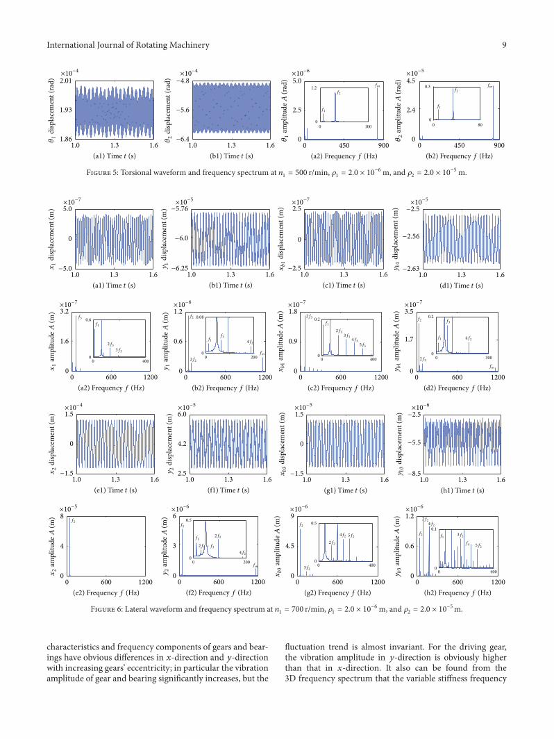
3.1. Analysis of the Effect of the Rotational Speed. Figures 6and 7 show the time domain waveforms and the frequencydomain responses, respectively, at 𝑛
1= 700 r/min. Com-
paring Figures 4 and 5 with Figures 6 and 7, the vibrationcharacteristics of gears and bearings have a lot of changes in𝑥-direction and 𝑦-direction with different rotational speed.It can be seen from Figure 6 that the harmonic componentshave obvious difference of vibration waveforms. Namely,not only do the higher-order harmonic components havesome increase, but also the vibration amplitudes have growthto some extent in 𝑥-direction and 𝑦-direction. The vibra-tion amplitude in 𝑦-direction is higher than those in 𝑥-direction (it is in accordance with the proposed analysis),and the waveform features become more complicated. Inthe figures of frequency domain response, the frequencycombination and frequency multiplication of the gears andbearing obviously appear in 𝑥-direction and 𝑦-direction.Theamplitude of 𝑓
2in 𝑦-direction of the driving gear becomes
largely obvious, but 𝑓1and the variable stiffness frequency
𝑓3become inconspicuous. For the driven gear, the waveform
features have no obvious change in 𝑥-direction, where therotational frequency 𝑓
2is the main frequency and the
meshing frequency𝑓𝑚decreases obviously.With the increase
of rotational speed, the amplitudes have growth to someextent. In addition, the rotational frequencies, the frequency
multiplication, and frequency combination components havesome significant differences, and the behaviors of the spurgear rotor bearing become more complicated.
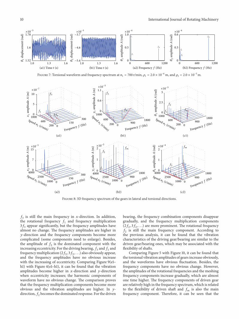
The torsional vibration of the driving and driven gears isshown in Figure 7 at 𝑛
1= 700 r/min. Comparing Figure 5
with Figure 7, the positive and negative torsional vibrationresponses have no difference with the rotational speed fluctu-ation, and the vibration amplitudes have little increase. In thefrequency domain response, it can be seen that the rotationalfrequencies 𝑓
1and 𝑓
2and the meshing frequency 𝑓
𝑚appear
obviously. In addition, the rotational frequency 𝑓2is higher
significantly, which is the dominated response in torsionaldirection of the driving gear.
The above part proposes a detailed analysis of the vibra-tion characteristics with 𝑛
1= 500 r/min and 𝑛
1= 700 r/min.
In order to analyze more deeply the spur gear system withchanging rotational speed, the 3D frequency spectrum of thesystem under different rotational speed condition is shownin Figure 8 (only the dynamic responses of gear are given).With the increasing of the rotational speed, in 𝑥-direction,the variable stiffness frequency 𝑓
3reaches a response peak
of gears at 𝑛1
= 900 r/min (𝑛2
= 3600 r/min), whichillustrates that the bearing has its own variable stiffnessfrequency. Therefore, the effect of the frequency componentof the bearing should be avoided during the system designingwork. In addition, other frequency components have nosignificant change. In 𝑦-direction, the rotational frequencycomponent 𝑓
1slightly appears. The rotational frequency 𝑓
2
and meshing frequency 𝑓𝑚
are the main frequency. How-ever, the changing trends for different frequency componentare in an opposite way. The meshing frequency 𝑓
𝑚in 𝑦-
direction decreases gradually; the rotational frequency 𝑓2
increases with changing rotational speed of the driving gear.In addition, the rotational frequency 𝑓
2of the driven gear
increases firstly and then decreases. Figure 8(c1-c2) shows 3Dfrequency spectrum of the gears in torsional direction. It canbe seen that the rotational frequencies f
1and f2andmeshing
frequency 𝑓𝑚appear obviously. 𝑓
1has no change evidently,
and 𝑓2increases firstly and then decreases, but the peaks
appear in a different position. The meshing frequency 𝑓𝑚
of driving gear in torsional direction strongly decreases andincreases in torsional direction of the driven gear. Comparingthe 3D frequency spectrum in lateral direction and torsionaldirection, it can be seen that the variable stiffness frequencycomponents are the main characteristics of driving anddriven gears in 𝑥-direction. The rotational frequency 𝑓
2and
meshing frequency 𝑓𝑚
are the dominated response, andother frequency components obviously appear, which is thesame result as that in the previous analysis. In addition,the amplitudes in torsional direction are larger than thosein lateral direction. Therefore, the torsional vibration is thedominated response.
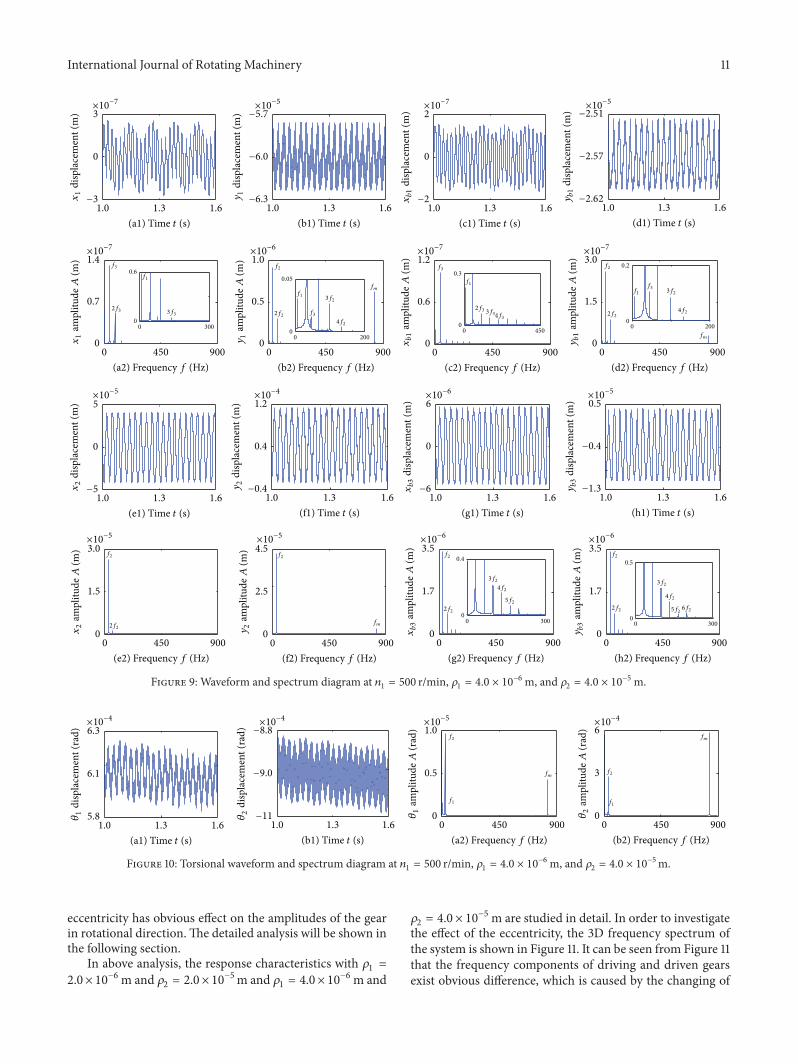
3.2. Analysis of the Effect of the Eccentricity. In this section,the eccentricity of driving and driven gears enlarges from𝜌1
= 2.0 × 10⁻⁶m and 𝜌2
= 2.0 × 10⁻⁵m to 𝜌1
=
4.0 × 10⁻⁶m and 𝜌2
= 4.0 × 10⁻⁵m. Figures 9 and 10show the vibration responses of the spur gear rotor bearingsystem. Comparing Figure 4 with Figure 9, the vibration
International Journal of Rotating Machinery 9
×10−6 ×10−5×10−4×10−4
0
1.2
000 100 80
0.3
f1f1
f2f2
fmfm
1.86
1.93
2.01
𝜃1
disp
lace
men
t (ra
d)
1.3 1.61.0
(a1) Time t (s)1.3 1.61.0
(b1) Time t (s)0 900450
(a2) Frequency f (Hz)
0
2.4
4.5
𝜃2
ampl
itude
A(r
ad)
0 900450
(b2) Frequency f (Hz)
−6.4
−5.6
−4.8
𝜃2
disp
lace
men
t (ra
d)
0
2.5
5.0
𝜃1
ampl
itude
A(r
ad)
Figure 5: Torsional waveform and frequency spectrum at 𝑛1= 500 r/min, 𝜌
1= 2.0 × 10⁻⁶m, and 𝜌
2= 2.0 × 10⁻⁵m.
×10−7 ×10−7
×10−7 ×10−7 ×10−7×10−6
×10−6
×10−6×10−6×10−6×10−5
×10−5 ×10−5
×10−5 ×10−5×10⁻⁴
0.1
00 400
0.5
00 400
0.5
00 200
0.6
00 400
0.08
00 200
0.2
00 400
0.2
00 300
f1f1f2
f2f2
f2
f4
fm
2f2
2f2
2f2
3f2
3f2
4f2
4f2
4f2
5f2
5f2
f1
f1
f1
f1
f2f2
f3
f3
f3
fm
fm2f22f2
4f24f2
3f34f3
5f3
2f3
2f3
3f3
2f3
−5.0
0
5.0
x1
disp
lace
men
t (m
)
1.3 1.61.0
(a1) Time t (s)
−6.25
−6.0
−5.76
y1
disp
lace
men
t (m
)
1.3 1.61.0
(b1) Time t (s)
−2.5
0
2.5
xb1
disp
lace
men
t (m
)1.3 1.61.0
(c1) Time t (s)
−2.63
−2.56
−2.5
yb1
disp
lace
men
t (m
)
1.3 1.61.0
(d1) Time t (s)
0
1.7
3.5
0 600 1200
(d2) Frequency f (Hz)0 600 1200
(c2) Frequency f (Hz)
0
0.9
1.8
0 600 1200
(b2) Frequency f (Hz)
0
0.6
1.2
0 600 1200
(a2) Frequency f (Hz)
0
1.6
3.2
1.3 1.61.0
(e1) Time t (s)
−1.5
0
1.5
2.5
4.2
6.0
1.3 1.61.0
(f1) Time t (s)
−1.5
0
1.5
1.0 1.61.3
(g1) Time t (s)
−8.5
−5.5
−2.5
1.0 1.61.3
(h1) Time t (s)
0
0.6
1.2
yb3
ampl
itude
A(m
)
0 600 1200
(h2) Frequency f (Hz)0 600 1200
(g2) Frequency f (Hz)
0
4.5
9
xb3
ampl
itude
A(m
)
0 600 1200
(f2) Frequency f (Hz)0 600 1200
(e2) Frequency f (Hz)
0
4
8
x2
ampl
itude
A(m
)
0
3
6
y2
ampl
itude
A(m
)
2f2 − f3
x1
ampl
itude
A(m
)x2
disp
lace
men
t (m
)
y1
ampl
itude
A(m
)y2
disp
lace
men
t (m
)
xb1
ampl
itude
A(m
)xb3
disp
lace
men
t (m
)
yb1
ampl
itude
A(m
)yb3
disp
lace
men
t (m
)
Figure 6: Lateral waveform and frequency spectrum at 𝑛1= 700 r/min, 𝜌
1= 2.0 × 10⁻⁶m, and 𝜌
2= 2.0 × 10⁻⁵m.
characteristics and frequency components of gears and bear-ings have obvious differences in 𝑥-direction and 𝑦-directionwith increasing gears’ eccentricity; in particular the vibrationamplitude of gear and bearing significantly increases, but the
fluctuation trend is almost invariant. For the driving gear,the vibration amplitude in 𝑦-direction is obviously higherthan that in 𝑥-direction. It also can be found from the3D frequency spectrum that the variable stiffness frequency
10 International Journal of Rotating Machinery
×10−3 ×10−3 ×10−4 ×10⁻⁴
f1f1
f2
f2 fm
fm
1.52
1.6
1.78
𝜃1
disp
lace
men
t (ra
d)
1.3 1.61.0
(a1) Time t (s)
−5.4
−4.6
−3.7
1.3 1.61.0
(b1) Time t (s)
0
0.5
1.0
0 600 1200
(a2) Frequency f (Hz)
0
0.3
0.6
𝜃2
ampl
itude
A(r
ad)
0 600 1200
(b2) Frequency f (Hz)𝜃2
disp
lace
men
t (ra
d)
𝜃1
ampl
itude
A(r
ad)
Figure 7: Torsional waveform and frequency spectrum at 𝑛1= 700 r/min, 𝜌
1= 2.0 × 10⁻⁶m, and 𝜌
2= 2.0 × 10⁻⁵m.
×10−7×10−5
×10−5×10−5
×10−5
×10−4
1000
600
200
1000
600
200
1000
600
200 0150
300
0150
300
Frequency f (Hz)
Frequency f (Hz)Frequency f (Hz)
Frequency f (Hz)
Frequency f (Hz)
Frequency f (Hz)
Speed n1 (r/min)
Speed n2 (r/min)
Speedn1 (r/min)
Speed n2 (r/min)
Speed n1 (r/min)
Speed n2 (r/min)
x2
ampl
itude
A(m
)
0
5
10
x1
ampl
itude
A(m
)
0
2.5
5
𝜃1
ampl
itude
A(r
ad)
0
0.6
1.1y1
ampl
itude
A(m
)
0
1
2
𝜃2
ampl
itude
A(r
ad)
0
1
2
y2
ampl
itude
A(m
)
0
7
15
0900
1800
0900
1800
0
9001800
0
900
1800
1000
2500
4000
10002500
4000
1000
2500
4000
(a1) (b1) (c1)
(a2) (b2) (c2)
f1
f1
f1
f1
f2
f2
f2
f2
f3
2f3
fm
fm
fm
fm
Figure 8: 3D frequency spectrum of the gears in lateral and torsional directions.
𝑓3is still the main frequency in 𝑥-direction. In addition,
the rotational frequency 𝑓1and frequency multiplication
3𝑓3appear significantly, but the frequency amplitudes have
almost no change. The frequency amplitudes are higher in𝑦-direction and the frequency components become morecomplicated (some components need to enlarge). Besides,the amplitude of 𝑓
2is the dominated component with the
increasing eccentricity. For the driving bearing,𝑓3and𝑓1and
frequencymultiplication (2𝑓3, 3𝑓3, . . .) also obviously appear,
and the frequency amplitudes have no obvious increasewith the increasing of eccentricity. Comparing Figure 9(e1–h1) with Figure 4(e1–h1), it can be found that the vibrationamplitudes become higher in 𝑥-direction and 𝑦-directionwhen eccentricity increases; the harmonic components ofwaveform have no obvious change. The comparison provesthat the frequency multiplication components become moreobvious and the vibration amplitudes are higher. In 𝑦-direction,𝑓
2becomes the dominated response. For the driven
bearing, the frequency combination components disappeargradually, and the frequency multiplication components(2𝑓2, 3𝑓2, . . .) are more prominent. The rotational frequency
𝑓2is still the main frequency component. According to
the previous analysis, it can be found that the vibrationcharacteristics of the driving gear/bearing are similar to thedriven gear/bearing ones, which may be associated with theflexibility of shafts.
Comparing Figure 5 with Figure 10, it can be found thatthe torsional vibration amplitudes of gears increase obviously,and the waveforms have obvious fluctuation. Besides, thefrequency components have no obvious change. However,the amplitudes of the rotational frequencies and the meshingfrequency components increase gradually, which are almostone time higher. The frequency components of driven gearare relatively high in the frequency spectrum, which is relatedto the flexibility of driven shaft and 𝑓
𝑚is also the main
frequency component. Therefore, it can be seen that the
International Journal of Rotating Machinery 11
×10−7 ×10−7
×10−7 ×10−7 ×10−7×10−6
×10−6
×10−6 ×10−6
×10−5 ×10−5
×10−5 ×10−5
×10−5 ×10−5
×10−4
f2f2f2
fm
2f22f2
f2
2f2
3f2
4f2
5f2
3f24f2
5f26f2
f1
f2
f3
f3
fm
2f2
3f2
4f2
f1
f1
f2
f3
fm
2f2
3f2
4f2
3f34f3
2f3
f3
f1
3f32f3
0.5
00 300
0.4
00 300
0.2
00 200
0.3
00 450
0.05
00 200
0.6
00 300
−3
0
3
x1
disp
lace
men
t (m
)
1.3 1.61.0
(a1) Time t (s)
−6.3
−6.0
−5.7
y1
disp
lace
men
t (m
)
1.3 1.61.0
(b1) Time t (s)
−2
0
2
xb1
disp
lace
men
t (m
)
1.3 1.61.0
(c1) Time t (s)
−2.62
−2.57
−2.51
yb1
disp
lace
men
t (m
)
1.3 1.61.0
(d1) Time t (s)
0
1.5
3.0
yb1
ampl
itude
A(m
)
0 900450
(d2) Frequency f (Hz)0 900450
(c2) Frequency f (Hz)
0
0.6
1.2
xb1
ampl
itude
A(m
)
0 900450
(b2) Frequency f (Hz)
0
0.5
1.0
y1
ampl
itude
A(m
)
0 900450
(a2) Frequency f (Hz)
0
0.7
1.4
x1
ampl
itude
A(m
)
−5
0
5
x2
disp
lace
men
t (m
)
1.3 1.61.0
(e1) Time t (s)
−0.4
0.4
1.2
y2
disp
lace
men
t (m
)
1.3 1.61.0
(f1) Time t (s)
−6
0
6xb3
disp
lace
men
t (m
)
1.3 1.61.0
(g1) Time t (s)
−1.3
−0.4
0.5
yb3
disp
lace
men
t (m
)
1.3 1.61.0
(h1) Time t (s)
0
1.7
3.5
yb3
ampl
itude
A(m
)
0 900450
(h2) Frequency f (Hz)0 900450
(g2) Frequency f (Hz)
0
1.7
3.5
xb3
ampl
itude
A(m
)
0 900450
(f2) Frequency f (Hz)
0
2.5
4.5
y2
ampl
itude
A(m
)
0 900450
(e2) Frequency f (Hz)
0
1.5
3.0
x2
ampl
itude
A(m
)
Figure 9: Waveform and spectrum diagram at 𝑛1= 500 r/min, 𝜌
1= 4.0 × 10⁻⁶m, and 𝜌
2= 4.0 × 10⁻⁵m.
×10−5×10−4 ×10−4 ×10⁻⁴
f1f1
f2
f2 fm
fm
5.8
6.1
6.3
𝜃1
disp
lace
men
t (ra
d)
1.3 1.61.0
(a1) Time t (s)
−11
−9.0
−8.8
𝜃2
disp
lace
men
t (ra
d)
1.3 1.61.0
(b1) Time t (s)
0
0.5
1.0
𝜃1
ampl
itude
A(r
ad)
0 900450
(a2) Frequency f (Hz)
0
3
6
𝜃2
ampl
itude
A(r
ad)
0 900450
(b2) Frequency f (Hz)
Figure 10: Torsional waveform and spectrum diagram at 𝑛1= 500 r/min, 𝜌
1= 4.0 × 10⁻⁶m, and 𝜌
2= 4.0 × 10⁻⁵m.
eccentricity has obvious effect on the amplitudes of the gearin rotational direction.The detailed analysis will be shown inthe following section.
In above analysis, the response characteristics with 𝜌1=
2.0 × 10⁻⁶m and 𝜌2= 2.0 × 10⁻⁵m and 𝜌
1= 4.0 × 10⁻⁶m and
𝜌2= 4.0 × 10⁻⁵m are studied in detail. In order to investigate
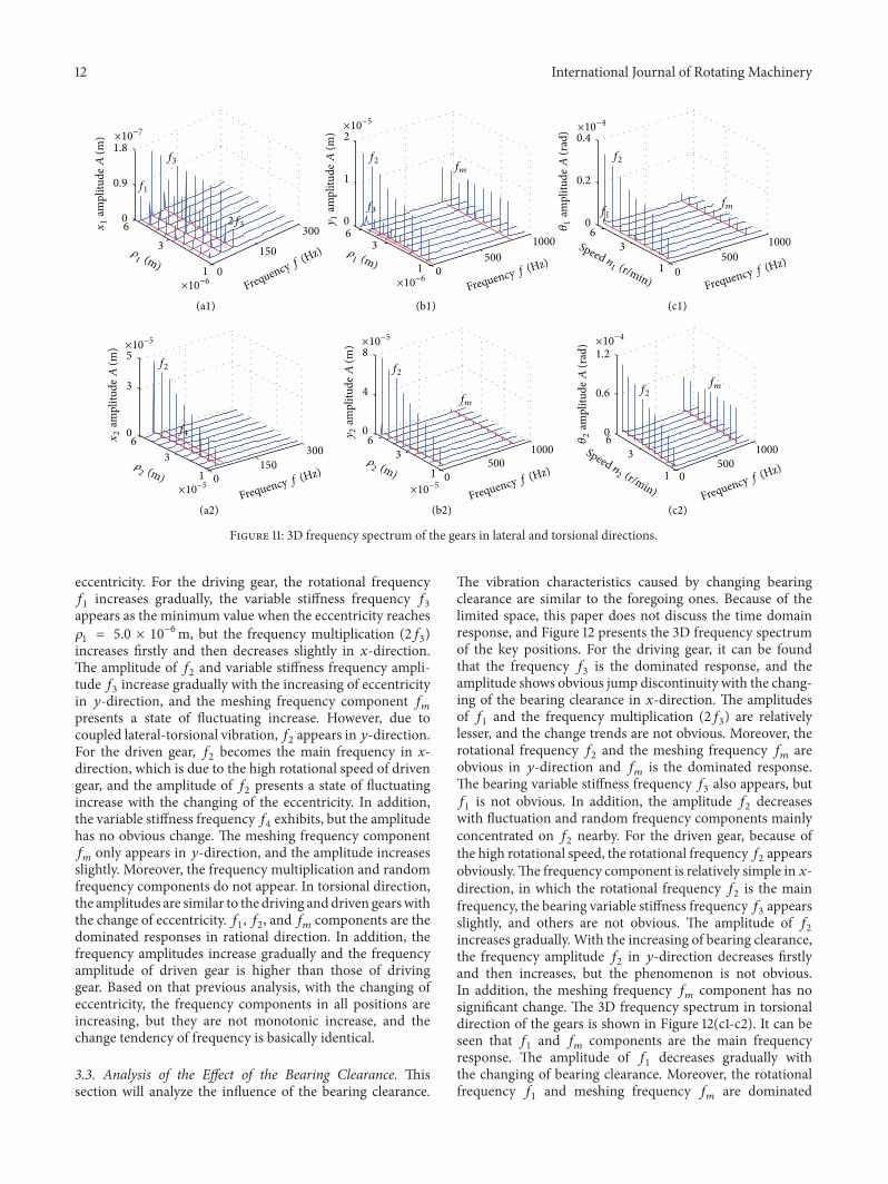
the effect of the eccentricity, the 3D frequency spectrum ofthe system is shown in Figure 11. It can be seen from Figure 11that the frequency components of driving and driven gearsexist obvious difference, which is caused by the changing of
12 International Journal of Rotating Machinery
f1
f1
f2f2
f2
f2
f2
f3
f3
2f3
fm
fm
fm
fm
×10−7×10−5
×10−5 ×10−5
×10−4
×10−4
Frequency f (Hz)
Frequency f (Hz)
Frequency f (Hz)
Frequency f (Hz)
Frequency f (Hz)
Frequency f (Hz)
Speed n1 (r/min)
Speed n2 (r/min)
𝜌1 (m)
𝜌2 (m)
𝜌1 (m)
𝜌2 (m)
6
3
1 0
150
300 63
1 0
500
10006
3
1 0500
1000
6
3
1 0150
3006
3
1 0500
10006
3
1 0500
1000
(c2)
(a1) (b1) (c1)
(a2) (b2)
0
0.9
1.8
x1
ampl
itude
A(m
)
0
1
2
y1
ampl
itude
A(m
)
0
0.2
0.4
𝜃1
ampl
itude
A(r
ad)
0
0.6
1.2
𝜃2
ampl
itude
A(r
ad)
0
4
8y2
ampl
itude
A(m
)
0
3
5
x2
ampl
itude
A(m
)
f4
×10−6×10−6
×10−5 ×10⁻⁵
Figure 11: 3D frequency spectrum of the gears in lateral and torsional directions.
eccentricity. For the driving gear, the rotational frequency𝑓1increases gradually, the variable stiffness frequency 𝑓
3
appears as the minimum value when the eccentricity reaches𝜌1
= 5.0 × 10⁻⁶m, but the frequency multiplication (2𝑓3)
increases firstly and then decreases slightly in 𝑥-direction.The amplitude of 𝑓
2and variable stiffness frequency ampli-
tude 𝑓3increase gradually with the increasing of eccentricity
in 𝑦-direction, and the meshing frequency component 𝑓𝑚
presents a state of fluctuating increase. However, due tocoupled lateral-torsional vibration,𝑓
2appears in 𝑦-direction.
For the driven gear, 𝑓2becomes the main frequency in x-
direction, which is due to the high rotational speed of drivengear, and the amplitude of 𝑓
2presents a state of fluctuating
increase with the changing of the eccentricity. In addition,the variable stiffness frequency 𝑓
4exhibits, but the amplitude
has no obvious change. The meshing frequency component𝑓𝑚only appears in 𝑦-direction, and the amplitude increases
slightly. Moreover, the frequency multiplication and randomfrequency components do not appear. In torsional direction,the amplitudes are similar to the driving anddriven gearswiththe change of eccentricity. 𝑓
1, 𝑓2, and 𝑓
𝑚components are the
dominated responses in rational direction. In addition, thefrequency amplitudes increase gradually and the frequencyamplitude of driven gear is higher than those of drivinggear. Based on that previous analysis, with the changing ofeccentricity, the frequency components in all positions areincreasing, but they are not monotonic increase, and thechange tendency of frequency is basically identical.
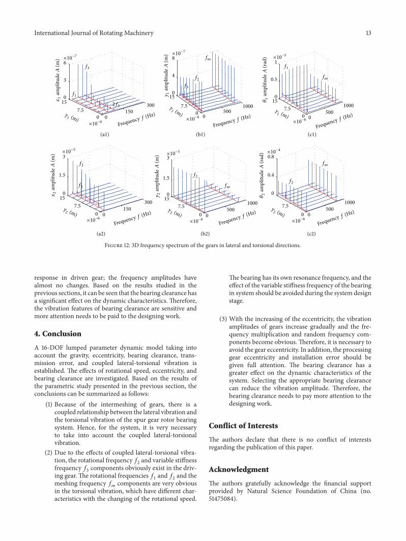
3.3. Analysis of the Effect of the Bearing Clearance. Thissection will analyze the influence of the bearing clearance.
The vibration characteristics caused by changing bearingclearance are similar to the foregoing ones. Because of thelimited space, this paper does not discuss the time domainresponse, and Figure 12 presents the 3D frequency spectrumof the key positions. For the driving gear, it can be foundthat the frequency 𝑓
3is the dominated response, and the
amplitude shows obvious jump discontinuity with the chang-ing of the bearing clearance in 𝑥-direction. The amplitudesof 𝑓1and the frequency multiplication (2𝑓
3) are relatively
lesser, and the change trends are not obvious. Moreover, therotational frequency 𝑓
2and the meshing frequency 𝑓
𝑚are
obvious in 𝑦-direction and 𝑓𝑚is the dominated response.
The bearing variable stiffness frequency 𝑓3also appears, but
𝑓1is not obvious. In addition, the amplitude 𝑓
2decreases
with fluctuation and random frequency components mainlyconcentrated on 𝑓
2nearby. For the driven gear, because of
the high rotational speed, the rotational frequency𝑓2appears
obviously.The frequency component is relatively simple in 𝑥-direction, in which the rotational frequency 𝑓
2is the main
frequency, the bearing variable stiffness frequency𝑓3appears
slightly, and others are not obvious. The amplitude of 𝑓2
increases gradually. With the increasing of bearing clearance,the frequency amplitude 𝑓
2in 𝑦-direction decreases firstly
and then increases, but the phenomenon is not obvious.In addition, the meshing frequency 𝑓
𝑚component has no
significant change. The 3D frequency spectrum in torsionaldirection of the gears is shown in Figure 12(c1-c2). It can beseen that 𝑓
1and 𝑓
𝑚components are the main frequency
response. The amplitude of 𝑓1decreases gradually with
the changing of bearing clearance. Moreover, the rotationalfrequency 𝑓
1and meshing frequency 𝑓
𝑚are dominated
International Journal of Rotating Machinery 13
f1
f1
f2
f2
f2f2
f3
f3
f3
2f3
fm
fm
fm
fm
×10−6
×10−6 ×10−6 ×10−6
×10−6 ×10−6
×10−7×10−7
×10−5
×10−5×10−5 ×10⁻⁴
Frequency f (Hz)
Frequency f (Hz)
Frequency f (Hz)
Frequency f (Hz)
Frequency f (Hz)
Frequency f (Hz)
𝛾1 (m)
𝛾1 (m)
𝛾1 (m)
𝛾2 (m)
𝛾2 (m)
𝛾2 (m) 0
5001000
0500
1000
0500
1000
0500
1000
(a1) (b1) (c1)
(a2) (b2) (c2)
15
7.5
0
15
7.5
0
7.5
0
0150
300
15
7.5
0
15
7.5
0
15
7.5
0
0150
300
0
3
6x1
ampl
itude
A(m
)
0
4
8
y1
ampl
itude
A(m
)
0
0.5
1
𝜃1
ampl
itude
A(r
ad)
0
0.4
0.8
𝜃2
ampl
itude
A(r
ad)
0
1.5
3y2
ampl
itude
A(m
)
0
1.5
3
x2
ampl
itude
A(m
)
Figure 12: 3D frequency spectrum of the gears in lateral and torsional directions.
response in driven gear; the frequency amplitudes havealmost no changes. Based on the results studied in theprevious sections, it can be seen that the bearing clearance hasa significant effect on the dynamic characteristics. Therefore,the vibration features of bearing clearance are sensitive andmore attention needs to be paid to the designing work.
4. Conclusion
A 16-DOF lumped parameter dynamic model taking intoaccount the gravity, eccentricity, bearing clearance, trans-mission error, and coupled lateral-torsional vibration isestablished. The effects of rotational speed, eccentricity, andbearing clearance are investigated. Based on the results ofthe parametric study presented in the previous section, theconclusions can be summarized as follows:
(1) Because of the intermeshing of gears, there is acoupled relationship between the lateral vibration andthe torsional vibration of the spur gear rotor bearingsystem. Hence, for the system, it is very necessaryto take into account the coupled lateral-torsionalvibration.
(2) Due to the effects of coupled lateral-torsional vibra-tion, the rotational frequency𝑓
2and variable stiffness
frequency 𝑓3components obviously exist in the driv-
ing gear. The rotational frequencies 𝑓1and 𝑓2and the
meshing frequency 𝑓𝑚components are very obvious
in the torsional vibration, which have different char-acteristics with the changing of the rotational speed.
The bearing has its own resonance frequency, and theeffect of the variable stiffness frequency of the bearingin system should be avoided during the system designstage.
(3) With the increasing of the eccentricity, the vibrationamplitudes of gears increase gradually and the fre-quency multiplication and random frequency com-ponents become obvious. Therefore, it is necessary toavoid the gear eccentricity. In addition, the processinggear eccentricity and installation error should begiven full attention. The bearing clearance has agreater effect on the dynamic characteristics of thesystem. Selecting the appropriate bearing clearancecan reduce the vibration amplitude. Therefore, thebearing clearance needs to pay more attention to thedesigning work.
Conflict of Interests
The authors declare that there is no conflict of interestsregarding the publication of this paper.
Acknowledgment
The authors gratefully acknowledge the financial supportprovided by Natural Science Foundation of China (no.51475084).
14 International Journal of Rotating Machinery
References
[1] H. H. Lin, R. L. Huston, and J. J. Coy, “On dynamic loading inparallel shaft transmissions,” Journal of Mechanism, Transmis-sions, andAutomation inDesign, vol. 110, no. 2, pp. 221–229, 1987.
[2] H. H. Lin, “Dynamic loading of super gear with linear orparabolic tooth profile modification,” Journal of Mechanism,Transmissions, andAutomation inDesign, vol. 29, no. 8, pp. 1115–1129, 1994.
[3] A. Raghothama and S. Narayanan, “Bifurcation and chaos ingeared rotor bearing system by incremental harmonic balancemethod,” Journal of Sound and Vibration, vol. 226, no. 3, pp.469–492, 1999.
[4] J. W. Lund, “Critical speeds, stability and response of a gearedtrain of rotors,” Journal of Mechanical Design, vol. 100, no. 3, pp.535–538, 1978.
[5] H. Iida, A. Tamura, K. Kikuch, and H. Agata, “Coupled tor-sional-flexural vibration of a shaft in a geared system of rotors,”Bulletin of the JSME, vol. 23, no. 186, pp. 2111–2117, 1980.
[6] A. Kahraman andR. Singh, “Non-linear dynamics of a spur gearpair,” Journal of Sound and Vibration, vol. 142, no. 1, pp. 49–75,1990.
[7] A. Kahraman and R. Singh, “Nonlinear dynamic of gearedrotor-bearing system with multiple clearances,” Journal ofSound and Vibration, vol. 144, no. 3, pp. 469–506, 1991.
[8] A. Kahraman and R. Singh, “Interactions between time-varyingmesh stiffness and clearance non-linearities in a geared system,”Journal of Sound and Vibration, vol. 146, no. 1, pp. 135–156, 1991.
[9] G. W. Blankenship and A. Kahraman, “Steady state forcedresponse of a mechanical oscillator with combined parametricexcitation and clearance type non-linearity,” Journal of Soundand Vibration, vol. 185, no. 5, pp. 743–765, 1995.
[10] Y. H. Sun, C. Zhang, F. Z. Pan, S. Chen, and F. Huang, “Dynamicmodel of a spur gear transmission system vibration,” ChineseJournal ofMechanical Engineering, vol. 36, no. 8, pp. 47–54, 2000(Chinese).
[11] W. Dou, N. Zhang, and Z.-S. Liu, “The coupled bending andtorsional vibrations of the high-speed geared rotor-bearingsystem,” Journal of Vibration Engineering, vol. 24, no. 4, pp. 385–393, 2011 (Chinese).
[12] A. S. Lee, J. W. Ha, and D.-H. Choi, “Coupled lateral andtorsional vibration characteristics of a speed increasing gearedrotor-bearing system,” Journal of Sound and Vibration, vol. 263,no. 4, pp. 725–742, 2003.
[13] J. H. Kuang and A. D. Lin, “The effect of tooth wear on thevibration spectrum of a spur gear pair,” Journal of Vibration andAcoustics, Transactions of the ASME, vol. 123, no. 3, pp. 311–317,2001.
[14] W. Y. Kim, H. H. Yoo, and J. T. Chung, “Dynamic analysis fora pair of spur gears with translational motion due to bearingdeformation,” Journal of Sound and Vibration, vol. 329, no. 21,pp. 4409–4421, 2010.
[15] P. Velex and M. Ajmi, “Dynamic tooth loads and quasi-static transmission errors in helical gears-approximate dynamicfactor formulae,”Mechanism andMachineTheory, vol. 42, no. 11,pp. 1512–1526, 2007.
[16] C.-J. Bahk and R. G. Parker, “Analytical solution for the nonlin-ear dynamics of planetary gears,” Journal of Computational andNonlinear Dynamics, vol. 6, no. 2, Article ID 021007, pp. 1–15,2011.
[17] M. Faggioni, F. S. Samani, G. Bertacchi, and F. Pellicano,“Dynamic optimization of spur gears,”Mechanism andMachineTheory, vol. 46, no. 4, pp. 544–557, 2011.
[18] F. L. Litvin, D. Vecchiato, K. Yukishima, A. Fuentes, I. Gonzalez-Perez, and K. Hayasaka, “Reduction of noise of loaded andunloadedmisaligned gear drives,”ComputerMethods in AppliedMechanics and Engineering, vol. 195, no. 41–43, pp. 5523–5536,2006.
[19] F. K. Omar, K. A. F. Moustafa, and S. Emam, “Mathematicalmodeling of gearbox including defects with experimental verifi-cation,” Journal of Vibration and Control, vol. 18, no. 9, pp. 1310–1321, 2012.
[20] H. Ma, J. Yang, R. Z. Song, S. Zhang, and B. Wen, “Effects of tiprelief on vibration responses of a geared rotor system,” Journalof Mechanical Engineering Science, vol. 228, no. 7, pp. 1132–1154,2014.
[21] H. Ma, Q. B. Wang, and J. Huang, “Vibration response analysisof gear coupled rotor system considering geometric eccentriceffect of helical gears,” Journal of Aerospace Power, vol. 28, no. 1,pp. 16–24, 2013 (Chinese).
[22] C.-W.Chang-Jian andC.-K. Chen, “Nonlinear dynamic analysisof a flexible rotor supported by micropolar fluid film journalbearings,” International Journal of Engineering Science, vol. 44,no. 15-16, pp. 1050–1070, 2006.
[23] S. P. Yang, Y. J. Shen, and X. D. Liu, “Nonlinear dynamics ofgear system based on incremental harmonic balance method,”Zhendong yuChongji/Journal of Vibration and Shock, vol. 24, no.3, pp. 40–95, 2005 (Chinese).
[24] Y. J. Shen, S. P. Yang, and X. D. Liu, “Nonlinear dynamics of aspur gear pair with time-varying stiffness and backlash based onincremental harmonic balance method,” International Journalof Mechanical Sciences, vol. 48, no. 11, pp. 1256–1263, 2006.
[25] J. Y. Yang, T. Peng, and T. C. Lim, “An enhanced multi-termharmonic balance solution for nonlinear period-one dynamicmotions in right-angle gear pairs,” Nonlinear Dynamics, vol. 67,no. 2, pp. 1053–1065, 2012.
[26] S.Wu,M. J. Zuo, andA. Parey, “Simulation of spur gear dynamicand estimation of fault growth,” Journal of Sound and Vibration,vol. 317, no. 3–5, pp. 608–624, 2008.
[27] L. Walha, T. Fakhfakh, andM. Haddar, “Nonlinear dynamics ofa two-stage gear system with mesh stiffness fluctuation, bearingflexibility and backlash,” Mechanism and Machine Theory, vol.44, no. 5, pp. 1058–1069, 2009.
[28] R. Russo, R. Brancati, and E. Rocca, “Experimental investiga-tions about the influence of oil lubricant between teeth on thegear rattle phenomenon,” Journal of Sound and Vibration, vol.321, no. 3–5, pp. 647–661, 2009.
[29] B. K. Han, M. K. Cho, C. Kim, C. H. Lim, and J. J. Kim, “Pre-diction of vibrating forces on meshing gears for a gear rattleusing a new multi-body dynamic model,” International Journalof Automotive Technology, vol. 10, no. 4, pp. 469–474, 2009.
[30] G. Chen, “Nonlinear dynamic of unbalance-looseness couplingfaults of rotor-ball bearing-stator coupling system,” ChineseJournal of Mechanical Engineering, vol. 44, no. 3, pp. 82–88,2008.

International Journal of
AerospaceEngineeringHindawi Publishing Corporationhttp://www.hindawi.com Volume 2014
RoboticsJournal of
Hindawi Publishing Corporationhttp://www.hindawi.com Volume 2014
Hindawi Publishing Corporationhttp://www.hindawi.com Volume 2014
Active and Passive Electronic Components
Control Scienceand Engineering
Journal of
Hindawi Publishing Corporationhttp://www.hindawi.com Volume 2014
International Journal of
RotatingMachinery
Hindawi Publishing Corporationhttp://www.hindawi.com Volume 2014
Hindawi Publishing Corporation http://www.hindawi.com
Journal ofEngineeringVolume 2014
Submit your manuscripts athttp://www.hindawi.com
VLSI Design
Hindawi Publishing Corporationhttp://www.hindawi.com Volume 2014
Hindawi Publishing Corporationhttp://www.hindawi.com Volume 2014
Shock and Vibration
Hindawi Publishing Corporationhttp://www.hindawi.com Volume 2014
Civil EngineeringAdvances in
Acoustics and VibrationAdvances in
Hindawi Publishing Corporationhttp://www.hindawi.com Volume 2014
Hindawi Publishing Corporationhttp://www.hindawi.com Volume 2014
Electrical and Computer Engineering
Journal of
Advances inOptoElectronics
Hindawi Publishing Corporation http://www.hindawi.com
Volume 2014
The Scientific World JournalHindawi Publishing Corporation http://www.hindawi.com Volume 2014
SensorsJournal of
Hindawi Publishing Corporationhttp://www.hindawi.com Volume 2014
Modelling & Simulation in EngineeringHindawi Publishing Corporation http://www.hindawi.com Volume 2014
Hindawi Publishing Corporationhttp://www.hindawi.com Volume 2014
Chemical EngineeringInternational Journal of Antennas and
Propagation
International Journal of
Hindawi Publishing Corporationhttp://www.hindawi.com Volume 2014
Hindawi Publishing Corporationhttp://www.hindawi.com Volume 2014
Navigation and Observation
International Journal of
Hindawi Publishing Corporationhttp://www.hindawi.com Volume 2014
DistributedSensor Networks
International Journal of