Embed Size (px)
Citation preview
Research ArticleDigital Hardware Realization of Forward and InverseKinematics for a Five-Axis Articulated Robot Arm
Bui Thi Hai Linh and Ying-Shieh Kung
Department of Electrical Engineering Southern Taiwan University of Science and Technology 1 Nan-Tai StreetYong-Kang District Tainan City 710 Taiwan
Correspondence should be addressed to Ying-Shieh Kung kungmailstustedutw
Received 16 August 2014 Accepted 13 September 2014
Academic Editor Stephen D Prior
Copyright copy 2015 B T Hai Linh and Y-S KungThis is an open access article distributed under theCreative CommonsAttributionLicense which permits unrestricted use distribution and reproduction in anymedium provided the originalwork is properly cited
When robot arm performs a motion control it needs to calculate a complicated algorithm of forward and inverse kinematicswhich consumes much CPU time and certainty slows down the motion speed of robot arm Therefore to solve this issue thedevelopment of a hardware realization of forward and inverse kinematics for an articulated robot arm is investigated In thispaper the formulation of the forward and inverse kinematics for a five-axis articulated robot arm is derived firstly Then thecomputations algorithm and its hardware implementation are described Further very high speed integrated circuits hardwaredescription language (VHDL) is applied to describe the overall hardware behavior of forward and inverse kinematics Additionallyfinite state machine (FSM) is applied for reducing the hardware resource usage Finally for verifying the correctness of forwardand inverse kinematics for the five-axis articulated robot arm a cosimulation work is constructed by ModelSim and SimulinkThe hardware of the forward and inverse kinematics is run by ModelSim and a test bench which generates stimulus to ModelSimand displays the output response is taken in Simulink Under this design the forward and inverse kinematics algorithms can becompleted within one microsecond
1 Introduction
The kinematics problem is an important study in the roboticmotion control The mapping from joint space to Cartesiantask space is referred to as direct kinematics and mappingfrom Cartesian task space to joint space is referred to asinverse kinematics [1] Because of the complexity of inversekinematics it is usually more difficult than forward kine-matics to find the solutions [2ndash5] In addition when robotmanipulator executes a motion control the complicatedinverse kinematics computation consumes much CPU timeand it certainty slows down the motion performance of robotmanipulator Therefore solving this problem becomes animportant issue
For the progress of very large scale integration (VLSI)technology the field programmable gate arrays (FPGAs) havebeen widely investigated due to their programmable hard-wired feature fast time to market shorter design cycleembedding processor low power consumption and higherdensity for the implementation of the digital system FPGA
provides a compromise between the special-purpose appli-cation specified integrated circuit (ASIC) hardware andgeneral-purpose processors Hence many practical appli-cations in industrial control [6] multiaxis motion control[7] and robotic control [8ndash10] have been studied Thereforefor speeding up the computational power the forward andinverse kinematics based on VHDL are studied in this paperAnd the VHDL is applied to describe the overall behavior ofthe forward and inverse kinematics
In recent years an electronic design automation (EDA)simulator link which can provide a cosimulation inter-face between MALTABSimulink [11] and HDL simulators-ModelSim [12] has been developed and applied in the designof the control system [13] Using it you can verify a VHDLVerilog or mixed-language implementation against yourSimulink model or MATLAB algorithm In MATLABSim-ulink environment it can generate stimuli to ModelSim andanalyze the simulationrsquos responses [11] In this paper a cosim-ulation by EDA simulator link is applied to the proposed
Hindawi Publishing CorporationMathematical Problems in EngineeringVolume 2015 Article ID 906505 10 pageshttpdxdoiorg1011552015906505
2 Mathematical Problems in Engineering
1205792 1205793
1205791
1205794
1205795
x0
x1 x2 x3x4
x5
y0
y1 y2y3
y4
y5
z2z1 z3
z4
z5z0
d5
d1
a2 a3
Figure 1The link coordinates system of a five-axis articulated robotarm
Table 1 Denavit-Hartenberg parameters for robot arm in Figure 1
Link 119894 119889119894(mm) 119886
119894(mm) 120572
119894120579119894
1 1198891= 275 0 120572
1= minus1205872 120579
1
2 0 1198862= 275 0 120579
2
3 0 1198863= 255 0 120579
3
4 0 0 1205724= minus1205872 120579
4
5 1198895= 195 0 0 120579
5
forward kinematics and inverse kinematics hardware Somesimulation results based on EDA simulator link will demon-strate the correctness and effectiveness of the forward andinverse kinematics
2 Description of the Forward andInverse Kinematics
A typical five-axis articulated robot arm is studied in thispaper Figure 1 shows its link coordinate system by Denavit-Hartenberg convention Table 1 illustrates the values of thekinematics parameters The forward kinematics of the artic-ulated robot arm is the transformation of joint space 119877
5
(1205791 1205792 1205793 1205794 1205795) to Cartesian space 1198773 (119909 119910 119911) Conversely
the inverse kinematics of the articulated robot armwill trans-form the coordinates of robot manipulator from Cartesianspace 1198773 (119909 119910 119911) to the joint space 1198775 (120579
1 1205792 1205793 1205794 1205795) The
computational procedure of forward and inverse kinematicsis shown in Figure 1 and Table 1
A coordinate frame is assigned to each link based onDenavit-Hartenberg notationThe transformation matrix foreach link from frame 119894 to 119894 minus 1 is given by
119894minus1119860119894= 119879 (119885 119889) 119879 (119885 120579) 119879 (119883 119886) 119879 (119883 120572)
=
[[[[
[
1 0 0 0
0 1 0 0
0 0 1 119889119894
0 0 0 1
]]]]
]
[[[[
[
cos 120579119894minus sin 120579
1198940 0
sin 120579119894
cos 1205791198940 0
0 0 1 0
0 0 0 1
]]]]
]
times
[[[[
[
1 0 0 119886119894
0 1 0 0
0 0 1 0
0 0 0 1
]]]]
]
[[[[
[
1 0 0 0
0 cos120572119894minus sin120572
1198940
0 sin120572119894
cos1205721198940
0 0 0 1
]]]]
]
=
[[[[
[
cos 120579119894minus cos120572
119894sin 120579119894
sin120572119894sin 120579119894
119886119894cos 120579119894
sin 120579119894
cos120572119894cos 120579119894minus sin120572
119894cos 120579119894119886119894sin 120579119894
0 sin120572119894
cos120572119894
119889119894
0 0 0 1
]]]]
]
(1)
where 119879(119885 120579) and 119879(119883 120572) present rotation and the 119879(119885 119889)and 119879(119883 120572) denote translation Substituting the parametersin Table 1 into (1) the coordinate five matrixes respected withfive axes of robot arm are shown as follows
01198601= 119879 (119885 119889
1) 119879 (119885 120579
1) 119879 (119883 0) 119879 (119883 minus
120587
2)
=
[[[[
[
cos 1205791
0 minus sin 1205791
0
sin 1205791
0 cos 1205791
0
0 minus1 0 1198891
0 0 0 1
]]]]
]
11198602= 119879 (119885 0) 119879 (119885 1205792) 119879 (119883 1198862) 119879 (119883 0)
=
[[[[
[
cos 1205792minus sin 120579
20 1198862cos 1205792
sin 1205792
cos 1205792
0 1198862sin 1205792
0 0 1 0
0 0 0 1
]]]]
]
21198603= 119879 (119885 0) 119879 (119885 1205793) 119879 (119883 1198863) 119879 (119883 0)
=
[[[[
[
cos 1205793minus sin 120579
30 1198863cos 1205793
sin 1205793
cos 1205793
0 1198863sin 1205793
0 0 1 0
0 0 0 1
]]]]
]
31198604= 119879 (119885 0) 119879 (119885 1205794) 119879 (119883 0) 119879 (119883 minus
120587
2)
=
[[[[
[
cos 1205794
0 minus sin 12057940
sin 1205794
0 cos 1205794
0
0 minus1 0 0
0 0 0 1
]]]]
]
41198605= 119879 (119885 119889
5) 119879 (119885 120579
5) 119879 (119883 0) 119879 (119883 0)
=
[[[[
[
cos 1205795minus sin 120579
50 0
sin 1205795
cos 1205795
0 0
0 0 1 1198895
0 0 0 1
]]]]
]
(2)
Mathematical Problems in Engineering 3
The forward kinematics of the end-effectorwith respect to thebase frame is determined by multiplying five matrices from(2) as given above An alternative representation of 0119860
5can
be written as
119877119879119867=01198605=01198601sdot11198602sdot21198603sdot31198604
sdot41198605Δ
[[[[
[
119899119909119900119909119886119909119901119909
119899119910119900119910119886119910119901119910
119899119911119900119911119886119911119901119911
0 0 0 1
]]]]
]
(3)
The (119899 119900 119886) are the orientation in the Cartesian coordinatesystem which is attached to the end-effector Using thehomogeneous transformation matrix to solve the kinematicsproblems its transformation specifies the location (positionand orientation) of the end-effector and the vector 119901 presentsthe position of end-effector of robot arm By multiplying fivematrices and substituting into (3) and then comparing all thecomponents of both sides after that we can solve the forwardkinematics of the five-axis articulated robot arm as follows
119899119909= cos 120579
1cos 120579234
cos 1205795+ sin 120579
1sin 1205795 (4)
119899119910= sin 120579
1cos 120579234
cos 1205795minus cos 120579
1sin 1205795 (5)
119899119911= minus sin 120579
234cos 1205795 (6)
119900119909= minus cos 120579
1cos 120579234
sin 1205795+ sin 120579
1cos 1205795 (7)
119900119910= minus sin 120579
1cos 120579234
sin 1205795minus cos 120579
1cos 1205795 (8)
119900119911= sin 120579
234sin 1205795 (9)
119886119909= minus cos 120579
1sin 120579234 (10)
119886119910= minus sin 120579
1sin 120579234 (11)
119886119911= minus cos 120579
234 (12)
119901119909= cos 120579
1(1198862cos 1205792+ 1198863cos 12057923minus 1198895sin 120579234) (13)
119901119910= sin 120579
1(1198862cos 1205792+ 1198863cos 12057923minus 1198895sin 120579234) (14)
119901119911=1198891minus 1198862sin 1205792minus 1198863sin 12057923minus 1198895cos 120579234 (15)
where
12057923= 1205792+ 1205793 (16)
120579234
= 1205792+ 1205793+ 1205794 (17)
The position vector 119901 directs the location of the originof the (119899 119900 119886) frame which is defined to let the end-effector
of robot arm by always gripping from a top down positionTherefore the matrix in (3) is set by the following form
119877119879119867=[[[
[
1 0 0 119909
0 minus1 0 119910
0 0 minus1 119911
0 0 0 1
]]]
]
(18)
Comparing the element (33) in (18) with (12) we obtained
cos 120579234
= 1 (19)
Therefore we can get
120579234
= 0 (20)
Further comparing the element (11) in (18) with (4) weobtained
cos (1205791minus 1205795) = 1 (21)
Therefore we can get
1205791minus 1205795= 0 or 120579
5= 1205791 (22)
Let us assume that
119887 = 1198862cos 1205792+ 1198863cos 12057923 (23)
then substituting (19)sim(22) into (13)sim(15) we can get thesequence for computations inverse kinematics as follows
119909 = cos 1205791sdot 119887 (24)
119910 = sin 1205791sdot 119887 (25)
119911 = 1198891minus 1198862sin 1205792minus 1198863sin 12057923minus 1198895 (26)
From (24) and (25) we can get
119887 = plusmnradic(1199092 + 1199102)
1205791= 1205795= 119886 tan 2 (
119910
119909)
(27)
From (23) and (26) we can get
1205793= arccos(
1198872+ (1198891minus 1198895minus 119911)2minus 1198862
2minus 1198862
3
211988621198863
) (28)
Once 1205793is obtained substitute it to (23) and (26) to get
119887 = (1198862+ 1198863cos 1205793) cos 120579
2+ 1198863sin 1205793sin 1205792
1198891minus 1198895minus 119911 = (119886
2+ 1198863cos 1205793) sin 120579
2+ 1198863sin 1205793cos 1205792
(29)
From (29) solve the linear equation in order to find the sin 1205792
and cos 1205792as
sin 1205792=(1198862+ 1198863cos 1205793) (1198891minus 1198895minus 119911) minus 119886
3119887 sin 120579
3
1198872 + (1198891minus 1198895minus 119911)2
cos 1205792=(1198862+ 1198863cos 1205793) 119887 + 119886
3sin 1205793(1198891minus 1198895minus 119911)
1198872 + (1198891minus 1198895minus 119911)2
(30)
4 Mathematical Problems in Engineering
Therefore 1205792can be derived as follows
1205792= 119886 tan 2 [
(1198862+ 1198863cos 1205793) (1198891minus 1198895minus 119911) minus 119886
3119887 sin 120579
3
(1198862+ 1198863cos 1205793) 119887 + 119886
3sin 1205793(1198891minus 1198895minus 119911)
]
(31)
Further from (17) and (20) 1205794is obtained as
1205794= minus1205792minus 1205793 (32)
Finally the forward kinematics and inverse kinematics ofthe five-axis articulated robot arm based on the assumptionin (18) in which the end-effector of the robot arm is alwaystoward the top downdirection can be summarized as follows
For computing the forward kinematics consider the fol-lowing steps
Step 1 Consider
end119909 = cos 1205791(1198862cos 1205792+ 1198863cos 12057923minus 1198895sin 120579234) (33)
Step 2 Consider
end119910 = sin 1205791(1198862cos 1205792+ 1198863cos 12057923minus 1198895sin 120579234) (34)
Step 3 Consider
end 119911 = 1198891minus 1198862sin 1205792minus 1198863sin 12057923minus 1198895cos 120579234 (35)
In the previous steps end119909 end119910 and end 119911 are the positionof end point which are the same as 119909 119910 and 119911 in (18)
For computing the inverse kinematics consider the fol-lowing steps
Step 1 Consider
1205791= 1205795= 119886 tan 2 (end119910 end119909) (36)
Step 2 Consider
119887 = plusmnradicend1199092 + end1199102 (37)
Step 3 Consider
1205793= 119886 cos(
1198872+ (1198891minus 1198895minus end 119911)2 minus 1198862
2minus 1198862
3
211988621198863
) (38)
Step 4 Consider
1198782= (1198862+ 1198863cos 1205793) (1198891minus 1198895minus end 119911) minus 119886
3119887 sin 120579
3 (39)
Step 5 Consider
1198622= (1198862+ 1198863cos 1205793) 119887 + 119886
3sin 1205793(1198891minus 1198895minus end 119911)
(40)
Step 6 Consider
1205792= 119886 tan 2 (119878
2 1198622) (41)
Step 7 Consider
1205794= minus1205792minus 1205793 (42)
The parameters of robot arm 1198862 1198863 1198891 1198895are shown in
Table 1
3 Computations of Trigonometric Functionand Its Hardware Implementation
Before performing the computation of the forward andinverse kinematics for five-axis articulated robot arm somekey trigonometric functions need to be built up as a compo-nent for being applied and those are sine function cosinefunction arctangent function and arccosine function Toincrease the computing accuracy LUT (look-up table) tech-nique and Taylor series expanse technique are used to thecomputational algorithm design of the arctangent functionand arccosine function However the computation algorithmused in these two functions is very similar therefore thedetailed design methods only sinecosine function andarctangent function are described as follows
31 Computation Algorithm and Hardware Realization of SineFunction and Cosine Function To compute sin(120579) and cos(120579)functions the 120579 = 120579
119868+ 120579119865is firstly defined in which 120579
119868and
120579119865represented the integer part and fraction part of the 120579
respectively Then the formulation of these two functions isexpanded as follows
sin (120579119868+ 120579119865) = sin (120579
119868) cos (120579
119865) + cos (120579
119868) sin (120579
119865)
cos (120579119868+ 120579119865) = cos (120579
119868) cos (120579
119865) minus sin (120579
119868) sin (120579
119865)
(43)
In the hardware design 120579 is adopted as 16-bit Q7 formatTherefore if 120579 is 0000001001000000 it represents 45 degreeIn addition four LUTs (look-up tables) are built up to storethe values of sin (120579
119868) cos (120579
119868) sin (120579
119865) and cos (120579
119865) functions
The LUT for sin (120579119868) and cos (120579
119868) functions stores 360 pieces
of data with 24-bit Q23 format and that for sin (120579119865) and
cos (120579119865) functions stores 128 pieces of data with the same 24-
bit Q23 format Therefore according to (43) the results ofsine and cosine with 16-bit Q15 format can be computed afterlooking up four tables In the realization finite state machine(FSM) is adopted and the example to compute the cosinefunction is shown in Figure 2 It presents four LUTs twomultipliers and one adder in hardware which manipulates 6steps to complete the overall computationDue to the fact thatthe operation of each step is 20 ns (50MHz) in FPGA a totalof 6 steps only need 120 ns operation time In addition theFPGA (Altera Cyclone IV) resource usage for the realizationof the sine or cosine function needs 232 logic elements (LEs)and 30720 RAM bits
32 Computation Algorithm and Hardware Realization ofArctangent Function The equation of arctangent function isshown as follows
120579 = 119886 tan 2 (119910
119909) (44)
where the inputs are 119909 and119910 and the output is 120579 Herein thereare two steps to evaluate the arctangent function
(1) First Step 1205791= 119891(119909) = tanminus1(119909) is computed by using
Taylor series expansion and the input values are definedwithin 1 le 119909 le 0 (or the output value 45∘ le 120579
1le 0∘)
Mathematical Problems in Engineering 5
120579(15middot middot7)
120579(6middot middot0)
S0 S1 S2 S3 S4 S5
LUT
LUT
LUT
LUT
(cos)
(sin)
(dcos)
(dsin)
Cos 16 =addr1(23middot middot8)
minus
+
times
times
mult r1(46middot middot23)
mult r2(46middot middot23)
Figure 2 FSM for computing the cosine function
The third-order polynomial is considered and the expressionwithin the vicinity of 119909
0is shown as follows
119891 (119909) cong 1198860 + 1198861 (119909 minus 1199090) + 1198862 (119909 minus 1199090)2+ 1198863(119909 minus 119909
0)3
(45)
with1198860=119891 (119909
0) = tanminus1 (119909
0)
1198861=1198911015840(1199090) =
1
1 + 1199092
0
1198862=11989110158401015840(1199090) =
minus21199090
(1 + 1199092
0)2
1198863=119891(3)(1199090) =
minus2 + 61199092
0
(1 + 1199092
0)3
(46)
Actually in realization only third-order expansion in (44)is not enough to obtain an accuracy approximation due tothe reason that the large error will occur when the input 119909is far from 119909
0 To solve this problem combining the LUT
technique and Taylor series expanse technique is consideredTo set up the LUT several specific values for 119909
0within the
range 1 le 119909 le 0 are firstly chosen then the parametersfrom 119886
0to 1198863in (46) are computed Those data included 119909
0
and 1198860to 1198863will be stored to LUT Following that when it
needs to compute tanminus1(119909) in (45) the 1199090which is the most
approximate to input 119909 and its related 1198860to 1198863will be selected
from LUT and then perform the computing task
(2) Second Step After completing the computation oftanminus1(119909) we can evaluate 120579 = 119886 tan 2(119910119909) further and letthe output suitable to the range be within minus180∘ le 120579 le 180
∘The formulation for each region in 119883-119884 coordinate is shownin Figure 3
In hardware implementation the inputs and output ofthe arctangent function are designed with 32-bit Q15 and 16-bit Q15 format respectively It consists of one main circuitwith FSM architecture and two components for computingthe divider and tanminus1(119909) functions However the design andimplementation of the tanminus1(119909) function is a major task Theinput and output values of component tanminus1(119909) all belong
I
IIIII
IV
V
VI VII
VIII
y
x
120579 = 90∘ + tanminus1(minusxy) 120579 = 90∘ minus tanminus1(x
y)
120579 = tanminus1(yx)
120579 = minustanminus1(minusyx)
120579 = minus90∘ + tanminus1( xminusy)120579 = minus90∘ minus tanminus1(minusx
minusy)
120579 = 180∘ minus tanminus1(minusyx)
180∘120579 = minus + tanminus1(minusyminusx)
Figure 3 Compute 120579 = 119886 tan 2(119910119909) of each region in 119883-119884 coordi-nates
S0 S1 S2 S3 S4 S5 S6
LUT
LUT
LUT
LUT
LUT
+
+
+
+
times
times
times
times
times
mult r1(30middot middot 15)
mult r1(30middot middot 15)
addr =xx(14middot middot 11)
xx
dxx
dxx
dxx
dxx
saa1
saa2
dxx3dxx2
minus
sita
120579 = tanminus1(x) cong a0 + a1(x minus x0) + a2(x minus x0)2+ a3(x minus x0)
3
(x0)
(a1)
(a0)
(a2)
(a3)
x0
a0
a0
a2
a2
a3 a3
a1
Figure 4 FSM to compute tanminus1(119909) function
to 16-bit Q15 format The FSM is employed to model thecomputation of tanminus1(119909) and is shown in Figure 4 which usestwo multipliers and one adder in the design The multiplierand adder applyAltera LPM (library parameterizedmodules)standard In Figure 4 it manipulates 7-step machine to carryout the overall computations of tanminus1(119909) The steps 119904
0sim 1199041
execute to look up 5 tables and 1199042sim 1199046perform the compu-
tation of polynomial in (45) Further according to the com-putation logic shown in Figure 3 it uses 16 steps to completethe 119886 tan 2(119910119909) function Due to the fact that the operationof each step is 20 ns (50MHz) in FPGA a total of 16 stepsonly need 320 ns operation time In addition the FPGA(Altera Cyclone IV) resource usage for the realization of thearctangent function needs 4143 LEs and 1280 RAM bits
4 Design and Hardware Implementationof ForwardInverse Kinematics and ItsSimulation Results
The block diagram of kinematics for five-axis articulatedrobot arm is shown in Figure 5 The inputs are the end-point position by end119909 end119910 and end 119911 which is relative
6 Mathematical Problems in Engineering
1205791(15 0)
1205792(15 0)
1205793(15 0)
1205794(15 0)
1205795(15 0)
a2(31 0)
a3(31 0)
d1(31 0)
d5(31 0)
endx(31 0)
endy(31 0)
endz(31 0)
(a)
1205791(15 0)
1205792(15 0)
1205793(15 0)
1205794(15 0)
1205795(15 0)
a2(31 0)
a3(31 0)
d1(31 0)
d5(31 0)
endx(31 0)
endy(31 0)
endz(31 0)
(b)
Figure 5 Block diagram for (a) forward kinematics and (b) inverse kinematics
1205793
1205794
12057923
120579234
120579234
120579234
1205792
COM
COM
A1 M1
M1
M1M2
A2
A1
A2
M1
M1
M2
M2
A1
for sinCOMfor sin
COMfor sin
COMfor sin
for cosCOMfor cos
COMfor cos
COMfor cos
sin1205791
sin1205791
sin12057923
sin1205792
sin120579234
1205791
1205791
1205792
1205792
12057923
12057923
cos1205791 cos120579234
cos1205791
cos1205792
cos12057923
S0 S7 S21 S28 S29 S30 S31 S32 S33S1 S15sim S22sim
minus
minus
minus
times
times
times
times
times
times
times
times
+
+
+
+
+
+ +
S2sim S8sim
a2
a3
a3
a2
var8var6var16
var8
var89
var89
var9
var2 var3
var1
var4var34
var1
var6
d5
d5
d1
endx
endy
endz
Figure 6 FSM for computing the forward kinematics
to (119909 119910 119911) as well as the mechanical parameters by 1198862 1198863
1198891 and 119889
5 The outputs are mechanical angles 120579
1sim 1205795 In
Figure 5 the parameters of mechanical length and the end-point position are designed with 32-bit Q15 data format andthe parameters of mechanical angle are designed with 16-bitQ7data format According to the formulations of forward andinverse kinematics which are described in Section 2 the finitestate machine (FSM) method is applied to design the hard-ware for reducing the usage of hardware resource Herein theFSM designs to compute the forward kinematics and inversekinematics are respectively shown in Figures 6 and 7 TheFSM will generate sequential signals and will step-by-stepcompute the forward kinematics and inverse kinematicsTheimplementation of inverse kinematics is developed byVHDL
In Figure 6 there are 34 steps to present the computations offorward kinematics and the circuit includes two multiplierstwo adders one component for sine function and onecomponent for cosine function In Figure 7 there are 47 stepsto perform the inverse kinematics and the circuit needs threemultipliers two dividers two adders one square root func-tion one component for arctangent function one componentfor arccosine function one component for sine function andone component for cosine function The notation ldquoCOMrdquo inFigures 6sim7 is represented with ldquocomponentrdquo For examplethe ldquoCOM for cosrdquo is the component of cosine functionThe designs of the component regarded as trigonometricfunction are described in previous section Due to the factthat the operation of each step is 20 ns (50MHz) in FPGA
Mathematical Problems in Engineering 7
S0 S2
S2
S1 S3 S4 S6 S7 S16 S20 S23
S23 S24 S25 S26 S27 S28 S29 S44S40 S45 S46
S5sim S8sim S17sim
sim
d1 minus d5a22 + a232a2a3
1205794
1205793
1205792
A1
A1
A1
A1A1 A2
A1S1
D1
D1
D2
M1
M1
M3
M1
M1
M2
M2
M2M3
+
+ + +
+
+
+
+
var1
var1 var1
var4
var5
var5
var2
var2
var2
var7
var7
var4
var3 var6 var5
minus
minus
minus
minusdivide
divide
divide
radic
times
timestimes
times
times
times times
times
times
var12
var22
COMfor atan2
COMfor atan2
COMfor acos
COMfor sin
a2a3
a3
1205793 sin1205793
1205791 1205795
C2
S2C2
endx
endy
endz
endy2
endyendx
endx2
Figure 7 FSM for computing the inverse kinematics
the executing time for the computation of forward andinverse kinematics is 680 ns and 940 ns respectively Inaddition the FPGA (Altera Cyclone IV) resource usage forthe realization of the forward kinematics IP and the inversekinematics IP is 1575 LEs and 30720 RAMbits and 9400 LEsand 84224 RAM bits respectively
The cosimulation architecture by ModelSimSimuLinkfor the proposed forward kinematics is shown in Figure 8 andthat for the inverse kinematics is shown in Figure 9whose works in ModelSim execute the function of thecomputing the forward and inverse kinematics The inputvalues toModelSim are provided fromSimulink and throughthe computation working in ModelSim output responsesare displayed to Simulink To confirm the correctness anembedded Matlab function for computing the forward andinverse kinematics is considered Under the cosimulation ofModelSim and Simulink architecture the simulation resultsare presented as follows
Mechanical parameters of the five-axis articulated robotarm are chosen by
1198862= 275 119886
3= 255
1198891= 275 119889
5= 195 (mm)
(47)
Simulation results of inverse kinematics with the followingtwo cases are listed in Table 2 The inputs of inverse kine-matics are the end-effectors of robot arm presented by end119909end119910 and end 119911 (mm) and the outputs are five joint anglespresented by 120579
1 1205792 1205793 1205794 1205795(degree)
In the first case the inputs end119909 end119910 and end 119911 arechosen as
end119909 = 300 end119910 = 299
end 119911 = minus150(48)
In the second case the inputs end119909 end119910 and end 119911 arechosen as
end119909 = 60 end119910 = 180
end 119911 = 450(49)
Simulation results of forward kinematics with the followingtwo cases are listed in Table 3The inputs of forward kinemat-ics are five joint angles presented by 120579
1 1205792 1205793 1205794 1205795(degree)
and the outputs are end-effectors presented by end 119909 end119910and end 119911 (mm)
In the first case the inputs 1205791 1205792 1205793 1205794 and 120579
5are chosen
as1205791= 449043477 120579
2= 48948685
1205793= 491952721 120579
4= minus540901472
1205795= 449043477
(50)
In the second case the inputs 1205791 1205792 1205793 1205794 and 120579
5are chosen
as1205791= 715650511 120579
2= minus994939347
1205793= 76703125 120579
4= 227812500
1205795= 715650511
(51)
From these two cases the absolute difference of end-effectorsend119909 end119910 and end 119911 which are calculated fromModelSimand from Matlab is less than 005mm and 120579
1to 1205795are less
than 001∘ It shows that the proposed forward and inversekinematics for the five-axis articulated robot arm are correctand effective
8 Mathematical Problems in Engineering
715650511
minus994939347
767060765
227878581
715650511
275
255
275
195
Convert
Convert
Convert
Convert
Convert
Convert
Convert
Convert
Convert
ModelSim
a2
a2
a3
a3
12057911205791
12057921205792
1205793
1205793
12057941205794
1205795
1205795
d1
d1
d5
d5
a2
a3
1205791
1205792
1205793
1205794
1205795
d1
d5
fcn
EmbeddedMatlab function
Forward kinematics
1965798
5897963
14746840
Kminus
Kminus
Kminus
Erorr of X
Erorr of Y
Erorr of Z
Gain3
Gain1
Gain2
Q15 of x
Q15 of y
Q15 of z
59991394042969
00086063533472114
17999154663086
00084537509296467
45003784179688
minus0037841604891696
60000000396316
18000000038179
45000000019198
minus+
minus+
minus+
endx
endy
endz
endxendx
endx
endyendy
endy
endzendz
endz
Figure 8 Cosimulation architecture of forward kinematics using ModelSim and SimuLink
Table 2 Two casesrsquo simulation results of inverse kinematics fromModelSim and Matlab
OutputInput
The 1st case (end119909 end119910 end 119911)(1) The 2nd case (end119909 end119910 end 119911)(2)
ModelSim Matlab Error ModelSim Matlab Error1205791
448984375 449043477 00059702 715703125 715650511 minus000526131205792
48906250 48948685 00042435 minus994843750 minus994939347 000955971205793
491953125 491952721 minus00000400 767060765 767031250 000295151205794
minus540859375 minus540901472 00042032 227878581 227812500 000660811205795
448984375 449043477 00059102 715703125 715650511 00052613(1) denotes the case 1 shown in (48)(2) denotes the case 2 shown in (49)
Table 3 Two casesrsquo simulation results of forward kinematics fromModelSim and Matlab
OutputInput
The 1st case (1205791 1205792 1205793 1205794 1205795)(1) The 2nd case (120579
1 1205792 1205793 1205794 1205795)(2)
ModelSim Matlab Error ModelSim Matlab Errorend119909 3000321650 3000000160 minus00321490 599913940 600000000 00086063end119910 2990496215 2990000160 minus00496054 1799915466 1800000000 00084537end 119911 minus1499700920 minus1499999999 minus00299906 4500378417 4500000000 minus00378416(1) denotes the case 1 shown in (50)(2) denotes the case 2 shown in (51)
Mathematical Problems in Engineering 9
60
180
450
275
255
275
195
x
y
z
a2
a3
d1
d5
Convert
Convert
Convert
Convert
Convert
Convert
Convert
a2
a3
d1
d5
ModelSim1205791
1205791
12057921205792
1205793
1205793
12057941205794
12057951205795
a2
a3
d1
d5
1205791
1205792
1205793
1205794
1205795
fcn
EmbeddedMatlab function
Inverse kinematics
Kminus
Kminus
Kminus
Kminus
Kminus
Gain3
Gain4
Gain5
Gain1
Gain2
+minus
+minus
+minus
+minus
+minus
Erorr of 1205791
Erorr of 1205792
Erorr of 1205793
Erorr of 1205794
Erorr of 1205795
1205791 m
1205792 m
1205793 m
1205794 m
1205795 m
715703125
minus99484375
76703125
2278125
715703125
minus000526132292201
minus00095597449695077
00029515830817672
00066081618877369
minus000526132292201
71565051177078
minus9949393474497
76706076583082
22787858161888
71565051177078
endx
endx
endy
endy
endz
endz
Figure 9 Cosimulation architecture of inverse kinematics using ModelSim and SimuLink
5 Conclusions
The forward kinematics and inverse kinematics of five-axisarticulated robot arm in which the end-effector of therobot arm is always toward the top down direction havebeen successfully demonstrated in this paper Through thecosimulation of ModelSim and Simulink the accuracy undertwo examples of forward and inverse kinematics with theresults of error of the end-effectors end119909 end119910 and end 119911is less than 005mm and the error for 120579
1sim 1205795is less than
001∘ Further the executing times for the computations offorward and inverse kinematics in FPGA are only 680 nsand 940 ns respectivelyThehigh speed computational powerand reasonable accuracy apparently increase the motionperformance of the five-axis articulated robot arm
Conflict of Interests
The authors declare that there is no conflict of interestsregarding the publication of this paper
Acknowledgment
This work was supported by National Science Council of theROC under Grant no NSC 100-2632-E-218 -001-MY3
References
[1] J J Craig Introduction to Robotics Mechanics amp ControlAddison-Wesley New York NY USA 1986
10 Mathematical Problems in Engineering
[2] W Shen J Gu and E E Milios ldquoSelf-configuration fuzzy sys-tem for inverse kinematics of robot manipulatorsrdquo in Pro-ceedings of the Annual Meeting of the North American FuzzyInformation Processing Society (NAFIPS rsquo06) pp 41ndash45 June2006
[3] P Falco and C Natale ldquoOn the stability of closed-loop inversekinematics algorithms for redundant robotsrdquo IEEETransactionson Robotics vol 27 no 4 pp 780ndash784 2011
[4] S-W Park and J-H Oh ldquoHardware realization of inverse kine-matics for robot manipulatorsrdquo IEEE Transactions on IndustrialElectronics vol 41 no 1 pp 45ndash50 1994
[5] G-S Huang C-K Tung H-C Lin and S-H Hsiao ldquoInversekinematics analysis trajectory planning for a robot armrdquo inProceedings of the 8th Asian Control Conference (ASCC rsquo11) pp965ndash970 twn May 2011
[6] E Monmasson L Idkhajine M N Cirstea I Bahri A Tisanand M W Naouar ldquoFPGAs in industrial control applicationsrdquoIEEE Transactions on Industrial Informatics vol 7 no 2 pp224ndash243 2011
[7] J U Cho Q N Le and J W Jeon ldquoAn FPGA-based multiple-axis motion control chiprdquo IEEE Transactions on IndustrialElectronics vol 56 no 3 pp 856ndash870 2009
[8] Y-S Kung K-H Tseng C-S Chen H-Z Sze and A-PWang ldquoFPGA-implementation of inverse kinematics and servocontroller for robot manipulatorrdquo in Proceedings of the IEEEInternational Conference on Robotics and Biomimetics (ROBIOrsquo06) pp 1163ndash1168 December 2006
[9] S Sanchez-Solano A J Cabrera I Baturone F J Moreno-Velo and M Brox ldquoFPGA implementation of embedded fuzzycontrollers for robotic applicationsrdquo IEEE Transactions onIndustrial Electronics vol 54 no 4 pp 1937ndash1945 2007
[10] C C Wong and C C Liu ldquoFPGA realisation of inverse kine-matics for biped robot based on CORDICrdquo Electronics Lettersvol 49 no 5 pp 332ndash334 2013
[11] The Mathworks MatlabSimulink Users Guide ApplicationProgram Interface Guide 2004
[12] ModeltechModelSim Reference Manual 2004[13] Y-S Kung N V Quynh C-C Huang and L-C Huang
ldquoSimulinkModelSim co-simulation of sensorless PMSM speedcontrollerrdquo in Proceedings of the IEEE Symposium on IndustrialElectronics and Applications (ISIEA rsquo11) pp 24ndash29 September2011
Submit your manuscripts athttpwwwhindawicom
Hindawi Publishing Corporationhttpwwwhindawicom Volume 2014
MathematicsJournal of
Hindawi Publishing Corporationhttpwwwhindawicom Volume 2014
Mathematical Problems in Engineering
Hindawi Publishing Corporationhttpwwwhindawicom
Differential EquationsInternational Journal of
Volume 2014
Applied MathematicsJournal of
Hindawi Publishing Corporationhttpwwwhindawicom Volume 2014
Probability and StatisticsHindawi Publishing Corporationhttpwwwhindawicom Volume 2014
Journal of
Hindawi Publishing Corporationhttpwwwhindawicom Volume 2014
Mathematical PhysicsAdvances in
Complex AnalysisJournal of
Hindawi Publishing Corporationhttpwwwhindawicom Volume 2014
OptimizationJournal of
Hindawi Publishing Corporationhttpwwwhindawicom Volume 2014
CombinatoricsHindawi Publishing Corporationhttpwwwhindawicom Volume 2014
International Journal of
Hindawi Publishing Corporationhttpwwwhindawicom Volume 2014
Operations ResearchAdvances in
Journal of
Hindawi Publishing Corporationhttpwwwhindawicom Volume 2014
Function Spaces
Abstract and Applied AnalysisHindawi Publishing Corporationhttpwwwhindawicom Volume 2014
International Journal of Mathematics and Mathematical Sciences
Hindawi Publishing Corporationhttpwwwhindawicom Volume 2014
The Scientific World JournalHindawi Publishing Corporation httpwwwhindawicom Volume 2014
Hindawi Publishing Corporationhttpwwwhindawicom Volume 2014
Algebra
Discrete Dynamics in Nature and Society
Hindawi Publishing Corporationhttpwwwhindawicom Volume 2014
Hindawi Publishing Corporationhttpwwwhindawicom Volume 2014
Decision SciencesAdvances in
Discrete MathematicsJournal of
Hindawi Publishing Corporationhttpwwwhindawicom
Volume 2014 Hindawi Publishing Corporationhttpwwwhindawicom Volume 2014
Stochastic AnalysisInternational Journal of
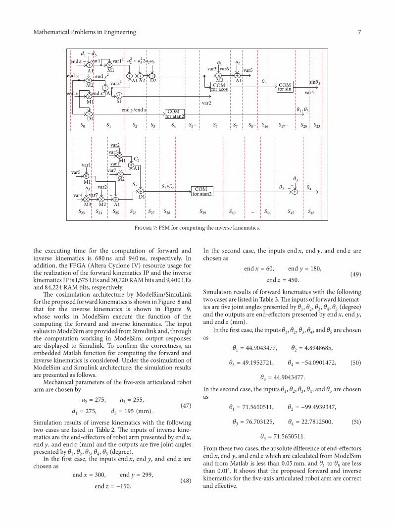
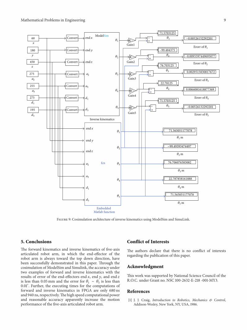


![Ong, Jia Jan (2016) Hardware realization of discrete wavelet ...eprints.nottingham.ac.uk/32583/1/[ONG JIA JAN] HARDWARE...Jia Jan Ong, Jia Hao Kong, L.-M. Ang, and K. P. Seng, “Implementation](https://img.pdfslide.us/doc/110x75/60776e3dea158f333776ca75/ong-jia-jan-2016-hardware-realization-of-discrete-wavelet-ong-jia-jan-hardware.jpg)