Embed Size (px)
Citation preview
Hindawi Publishing CorporationMathematical Problems in EngineeringVolume 2013 Article ID 757656 8 pageshttpdxdoiorg1011552013757656
Research ArticleCalculation of Lightning Transient Responses onWind Turbine Towers
Xiaoqing Zhang and Yongzheng Zhang
School of Electrical Engineering Beijing Jiaotong University Beijing 100044 China
Correspondence should be addressed to Yongzheng Zhang zhangyz2126com
Received 12 December 2012 Revised 16 March 2013 Accepted 16 March 2013
Academic Editor Massimo Scalia
Copyright copy 2013 X Zhang and Y Zhang This is an open access article distributed under the Creative Commons AttributionLicense which permits unrestricted use distribution and reproduction in any medium provided the original work is properlycited
An efficient method is proposed in this paper for calculating lightning transient responses on wind turbine towers In the proposedmethod the actual tower body is simplified as a multiconductor grid in the shape of cylinder A set of formulas are givenfor evaluating the circuit parameters of the branches in the multiconductor grid On the basis of the circuit parameters themulticonductor grid is further converted into an equivalent circuit The circuit equation is built in frequency-domain to takeinto account the effect of the frequency-dependent characteristic of the resistances and inductances on lightning transients Thelightning transient responses can be obtained by using the discrete Fourier transformwith exponential sampling to take the inversetransform of the frequency-domain solution of the circuit equation A numerical example has been given for examining theapplicability of the proposed method
1 Introduction
Lightning is a complex atmospheric discharge phenomenonThe recorded lightning current has a highest peak value ofaround 300 kAand a duration of a fewhundredmicroseconds[1] In fact this peak value rarely occurs in China Themedian peak value is 26 kA occurring with 50 probabilityaccording to Chinese measured data [2] With respect towind turbines (WTs) the lightning strokes can be classifiedinto two main types downward flash and upward flashThe WTs with the height exceeding 100m are mostly struckby upward flash The impacts of lightning on WTs rangefrom disturbances on control electronics damages to singlecomponents such as generator and sensor to fires resultingin a complete loss of the installation The control systemfrequently suffering from lightning transient overvoltages istypically the electrical control cabinet in the bottom of theWT tower Its damage accounts for about 40 of all lightningdamage events of WTs in the west of China Furthermoreoffshore WTs are often equipped with relatively advancedequipment such as communication antenna transponderGPS receiver sea marking light air traffic warning light
fog-horns and meteorological instrument all of which areespecially susceptible to lightning damage Since accessingWTs offshore is not as easy as on land lightning damage toWTs offshore can result in significantly higher costs of repairand maintenance In view of the seriousness of lightningstroke to WTs the lightning protection design has beenregarded with more and more attention In the lightningprotection design of WTs the need exists for determiningthe lightning transient responses on the WT tower sincethe tower body is the longest conducting path of lightningcurrent in the WT structure The previous methods usuallymodeled the WT tower as a transmission line [3 4] or acapacitance chain [5] Although the previous methods aresimple they cannot give the lightning transient responses indifferent parts on the tower body owing to their neglectingthe structural feature of the tower body For an improvementin the lightning transient calculation ofWTs a novel methodis proposed in this paper The proposed method representsthe actual WT tower in the shape of the circular trun-cated cone as an equivalent cylindrical shell The cylindricalshell is further subdivided into a discrete multiconductorgrid A set of analytic formulas are deduced for evaluating
2 Mathematical Problems in Engineering
Earth surface
119908
1199031
ℎ
1199032
(a)
1199030
Earth surface
ℎ
1199030
(b)
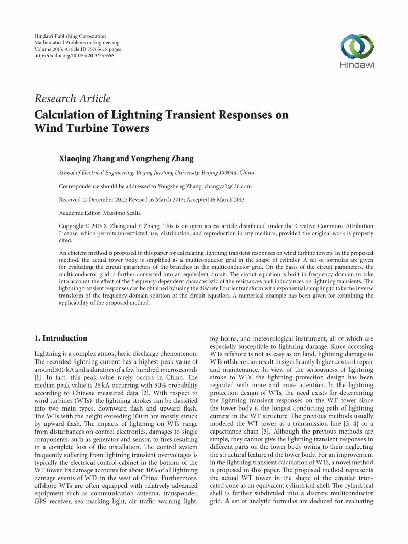
Figure 1 Geometric simplification of WT tower (a) hollow circular truncated cone (b) cylindrical shell
the circuit parameters of the branches in the multiconductorgrid Based on the circuit parameters the multiconductorgrid is converted into an equivalent circuit The hybridequation is built in the frequency-domain for the equivalentcircuit and then the discrete Fourier transform with expo-nential sampling is used to obtain the lightning transientresponses in different parts on the tower body As com-pared to the traditional time-domain method [6] the pro-posed method can give due consideration to the frequency-dependent characteristic of the branch impedance directlyin the frequency-domain and present better applicability tothe lightning transient calculation A numerical example hasalso been given for checking the validity of the proposedmethod
2 Discretization Treatment of WT Tower
An actual WT tower is usually a hollow circular truncatedcone as shown in Figure 1(a) Since ℎ ≫ 119903
1and 119903
2 and
1199032is not much larger than 119903
1 the actual tower body may
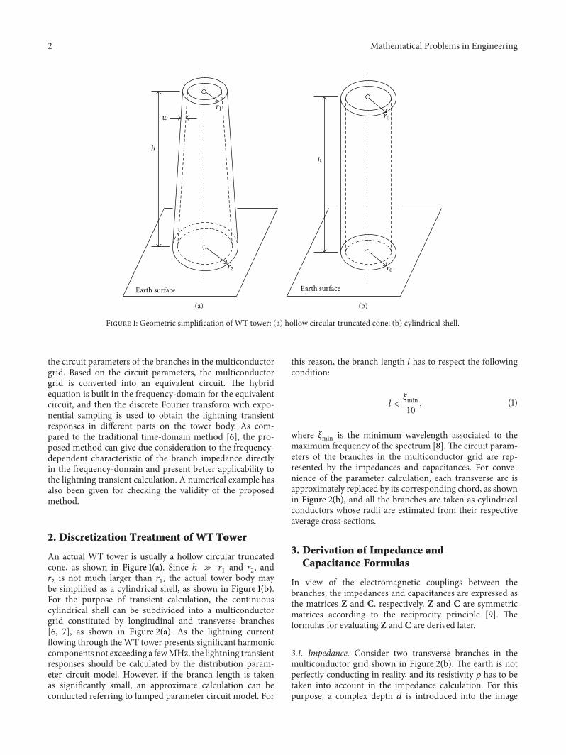
be simplified as a cylindrical shell as shown in Figure 1(b)For the purpose of transient calculation the continuouscylindrical shell can be subdivided into a multiconductorgrid constituted by longitudinal and transverse branches[6 7] as shown in Figure 2(a) As the lightning currentflowing through theWT tower presents significant harmoniccomponents not exceeding a fewMHz the lightning transientresponses should be calculated by the distribution param-eter circuit model However if the branch length is takenas significantly small an approximate calculation can beconducted referring to lumped parameter circuit model For
this reason the branch length 119897 has to respect the followingcondition
119897 lt120585min10 (1)
where 120585min is the minimum wavelength associated to themaximum frequency of the spectrum [8] The circuit param-eters of the branches in the multiconductor grid are rep-resented by the impedances and capacitances For conve-nience of the parameter calculation each transverse arc isapproximately replaced by its corresponding chord as shownin Figure 2(b) and all the branches are taken as cylindricalconductors whose radii are estimated from their respectiveaverage cross-sections
3 Derivation of Impedance andCapacitance Formulas
In view of the electromagnetic couplings between thebranches the impedances and capacitances are expressed asthe matrices Z and C respectively Z and C are symmetricmatrices according to the reciprocity principle [9] Theformulas for evaluating Z and C are derived later
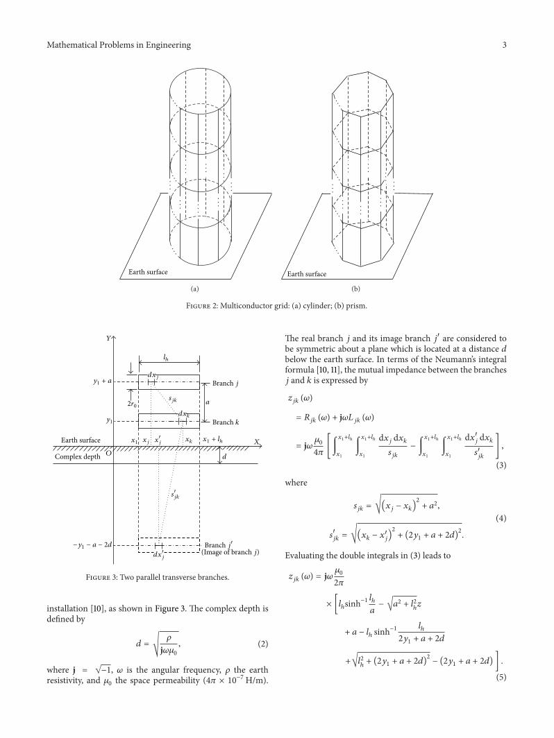
31 Impedance Consider two transverse branches in themulticonductor grid shown in Figure 2(b) The earth is notperfectly conducting in reality and its resistivity 120588 has to betaken into account in the impedance calculation For thispurpose a complex depth 119889 is introduced into the image
Mathematical Problems in Engineering 3
middot middot middot
middot middot middotmiddot middot middot
middot middot middotmiddot middot middot
Earth surface
(a)
middot middot middot
middot middot middotmiddot middot middot
middot middot middotmiddot middot middot
Earth surface
(b)
Figure 2 Multiconductor grid (a) cylinder (b) prism
119884
1199101 + 119886
1199101
119874
21199030
119897ℎ
119889119909119896
119889119909119895
119886
119909119895 119909119896 1199091 + 119897ℎ 119883
119889
Earth surface
Complex depth
minus1199101 minus 119886 minus 2119889
Branch 119895
Branch 119896
119904119895119896
119909998400119895
119889119909998400119895
Branch 119895998400
(Image of branch 119895)
119904998400119895119896
1199091
Figure 3 Two parallel transverse branches
installation [10] as shown in Figure 3 The complex depth isdefined by
119889 = radic120588
j1205961205830
(2)
where j = radicminus1 120596 is the angular frequency 120588 the earthresistivity and 120583
0the space permeability (4120587 times 10minus7Hm)
The real branch 119895 and its image branch 1198951015840 are considered tobe symmetric about a plane which is located at a distance 119889below the earth surface In terms of the Neumannrsquos integralformula [10 11] the mutual impedance between the branches119895 and 119896 is expressed by
119911119895119896(120596)
= 119877119895119896(120596) + j120596119871
119895119896(120596)
= j120596 12058304120587[int
1199091+119897ℎ
1199091
int
1199091+119897ℎ
1199091
d119909119895d119909119896
119904119895119896
minus int
1199091+119897ℎ
1199091
int
1199091+119897ℎ
1199091
d1199091015840119895d119909119896
1199041015840119895119896
]
(3)
where
119904119895119896= radic(119909
119895minus 119909119896)2
+ 1198862
1199041015840
119895119896= radic(119909
119896minus 1199091015840119895)2
+ (21199101+ 119886 + 2119889)
2
(4)
Evaluating the double integrals in (3) leads to
119911119895119896(120596) = j120596 1205830
2120587
times [119897ℎsinhminus1
119897ℎ
119886minus radic1198862 + 1198972
ℎ119911
+ 119886 minus 119897ℎsinhminus1
119897ℎ
21199101+ 119886 + 2119889
+radic1198972ℎ+ (21199101+ 119886 + 2119889)
2
minus (21199101+ 119886 + 2119889) ]
(5)
4 Mathematical Problems in Engineering
The self-impedance 119885119895119895(120596) of the transverse branch 119895 is
obtained by substituting 119886 = 1199030into (5) In a similar way
themutual impedance between two longitudinal branches asshown in Figure 4 is given by
119885119898119899(120596)
= j120596 12058302120587
times [(21199101+ 119897V + 2119889) sinh
minus1 21199101 + 119897V + 2119889
119887
+ radic(21199101+ 119897V + 2119889)
2
+ 1198872 minus (1199101+ 119897V + 119889)
times sinhminus12 (1199101+ 119897V + 119889)
119887minus1
2
radic4(1199101+ 119897V + 119889)
2
+ 1198872
minus (1199101+ 119889) sinhminus1
2 (1199101+ 119889)
119887
+1
2
radic4(1199101+ 119889)2
+ 1198872 + 119897V sinhminus1 119897V
119887minus radic1198872 + 1198972V + 119887]
(6)
In (6) letting 119887 = 1199030gives the self-impedance 119885
119898119898(120596) of the
longitudinal branch119898After the self and mutual impedances are calculated for
a coupled branch unit with 119873 transverse or longitudinalbranches by using (5) or (6) the impedance matrix Z can beformed as
Z = [119877119895119896(120596)]119873times119873
+ j120596[119871119895119896(120596)]119873times119873
= [119911119895119896(120596)]119873times119873
(7)
or
Z = [119877119898119899(120596)]119873times119873
+ j120596[119871119898119899(120596)]119873times119873
= [119911119898119899(120596)]119873times119873
(8)
It is clear from (7) and (8) that the resistance and inductancein the impedance exhibit a pronounced frequency-dependentcharacteristic owing to introducing the complex depth 119889 Ifthe earth is assumed to be perfectly conducting (120588 = 0) thecomplex depth119889 is zero according to (2) Substitution of119889 = 0into (5) or (6) shows that the real part of the impedance is alsozero As a result the impedancematrixZ is further simplifiedas
Z0= j120596L
0 (9)
where L0is the constant inductancematrix which is indepen-
dent on the angular frequency 120596
32 Capacitance In the calculation of capacitances thefrequency effect on the charge density distribution can besignificantly neglected since the charge attenuation constant120591 = 120576120588 (120576 is the permittivity) is rather small in the frequencyrange of lightning transient for both the branch conductorand the earth [12]Therefore the capacitances of the branchescan still be calculated on the assumption that the earth isperfectly conducting On the basis of the electromagnetic
119904mn
minus1199101 minus 119897 minus 2119889
mn
119884
1199101
119874
119883
119889
Earth surface
Complex depth
119889119910998400119898
Branch 119898998400
(Image of branch 119898)
119904998400
119910998400119898
minus1199101 minus 2119889
1199091 1199091 + 119887119887
119910119899
119910119898
1199101 + 119897119889119910119898
21199030
119889119910119899
119897
Branch 119898 Branch 119899
Figure 4 Two parallel longitudinal branches
analogy [9] the product of the impedance matrix Z0= j120596L
0
and the admittance matrix Y = j120596C of the coupled branchesbecomes diagonal with negative elements determined fromspace permeability 120583
0and permittivity 120576
0[10] as
Z0sdot Y = (j120596L
0) sdot (j120596C) = minus (1205962120576
01205830)E (10)
where C is capacitance matrix of the coupled branches and Eis the unit matrix Consequently the capacitance matrix canbe obtained as
C = 12057601205830Z0 (11)
4 Equivalent Circuit Model
During a lightning stroke the lightning current is usuallyinjected to the tower body from its top and then dissipatedin the earth by the earthing system This process can beillustrated in Figure 5 where the earthing system is sim-ply represented as the earthing resistances (119877
119892) Once the
impedance and capacitance parameters are obtained usingthe formulas given earlier each coupled branch unit inthe multiconductor grid can equivalently be represented bya 120587-circuit consisting of the series impedance and shuntcapacitance [6 13] Figures 6(a) and 6(b) show the 120587-circuitrepresenting three coupled branches If the circuit parametersare expressed in matrix form Figure 6(b) can be furtherdepicted as a compact 120587-circuit as shown in Figure 6(c)
With all the coupled branch units in the multiconductorgrid replaced by the 120587-circuits Figure 5 is converted intoan equivalent circuit consisting of resistances inductancesand capacitances The lightning current is modeled as acurrent source and applied to the top node of the equivalent
Mathematical Problems in Engineering 5
Lightning current
119894
119877119892
119877119892
119877119892
middot middot middotmiddot middot middot
middot middot middot
middot middot middotmiddot middot middot
Figure 5 Injection of lightning current to tower body
circuitThe lightning transient responses in different parts onthe tower body can be obtained by performing a transientcalculation for the equivalent circuit
5 Circuit Equation and Its Numerical Solution
In order to take into account the frequency-dependentcharacteristic of the resistances and inductances in seriesimpedances on lightning transients the circuit equation isbuilt in frequency-domain The circuit components of theequivalent circuit are numbered in the sequence of shuntcapacitance series impedance and lightning current sourceIn accordance with the component number the incidencematrix of the equivalent circuit is written as
119860 = [119860119862 119860 im 119860119878] (12)
and the relevant current vector is
I (120596) = [I119862(120596) Iim (120596) 119868119878 (120596)]
119879
(13)
where the subscripts 119862 im and 119878 denote shunt capacitanceseries impedance and lightning current source respectivelyFrom Kirchhoff rsquos current law the node current equation isderived from (12) and (13) as
119860I (120596) = 119860119862I119862(120596) + 119860 imIim (120596) + 119860119878119868119878 (120596) = 0 (14)
Substituting 119860119862Y119862119860119879
119862U119899(120596) for 119860
119862I119862(120596) in (14) gives
119860119862Y119862119860119879
119862U119899(120596) + 119860 imIim (120596) + 119860119878119868119878 (120596) = 0 (15)
where Y119862is the shunt capacitive admittance matrix Let
U119899(120596) and Zim be the node voltage vector and series
impedance matrix respectively The branch equation of theseries impedance is given by
119860119879
imU119899 (120596) minus ZimIim (120596) = 0 (16)
Hence the hybrid equation of the equivalent circuit can bebuilt by merging (15) and (16) as
[119860119862Y119862119860119879
119862119860 im
119860119879
im minusZim][
U119899(120596)
Iim (120596)] = [
minus119860119878119868119878(120596)
0] (17)
On the right hand of (17) lightning current source 119868119878(120596) is
the Fourier transform of the injected lightning current 119894 (seeFigure 5) 119894 is usually expressed by the double exponentialfunction [14]
119894 = 119868 (119890minus120572119905minus 119890minus120573119905) (18)
In accordance with the Chinese national standard [2] thewaveform parameter of 119894 is 2650 120583s This gives 120572 = 15 times10minus2120583sminus1and 120573 = 186 120583sminus1 by using the least square fitting
method [15] The peak current 119868 takes the value of 100 kA inlight of the severe lightning stroke condition Thus findingthe Fourier transform of (18) gives
119868119878(120596) =
(120573 minus 120572) 119868
(120572 + 119895120596) (120573 + 119895120596) (19)
By taking the 119868119878(120596) as the excitation the frequency responses
U119899(120596) and Iim(120596) can be obtained by solving (17) For each
given angular frequency 120596 (17) is a system of complex linearalgebraic equations and can be generally written as
ΛX (120596) = b (20)
where
Λ = [Λ119895119896]119872times119872
= [119860119862Y119862119860119879
119862119860 im
119860119879
im minusZim]
119872times119872
X (120596) = [119883119895(120596)]119872times1
= [
U119899(120596)
Iim (120596)]
119872times1
b = [119887119895]119872times1
= [
minus119860119878119868119878(120596)
0]
119872times1
(21)
where 119872 is the order of the coefficient matrix in (17)The Gauss elimination with column pivoting is employed
6 Mathematical Problems in Engineering
1198601 1198611
1198602 1198612
1198603 1198613
1
2
3
(a)
12j120596C13
12j120596C12
12j120596C33
12j120596C22
12j120596C23
12j120596C22
12j120596C33
12j120596C23
12j120596C13
12j120596C12
1198601
1198602
1198603
1198611
1198612
1198613
11988533(120596)
11988513(120596)
11988523(120596)
11988522(120596)
11988512(120596)
12j120596C11
12j120596C1111988511(120596)
(b)119885
119860 119861
12j120596C 1
2j120596C
(c)
Figure 6 120587-circuit of three branches (a) three coupled branches (b) coupled 120587-circuit and (c) compact 120587-circuit expressed in matrix
1199030
P111
P112P113
P114
P115
P101
P17
P18 P16
P15
P14P13P21
P31
P11
P12
Figure 7 Multiconductor grid of a 15MWWT tower
to solve (20) It consists of two main phases the forwardelimination and the back substitution After performing119872minus1step elimination operations the original matrix Λ in (20) isconverted into an upper triangular matrix
[[[[[[[[[[[[[[[
[
Λ(1)
11Λ(1)
12sdot sdot sdot Λ
(1)
1119896sdot sdot sdot Λ
(1)
1119872
0 Λ(2)
22sdot sdot sdot Λ
(2)
2119896sdot sdot sdot Λ
(2)
2119872
sdot sdot sdot
sdot sdot sdot
0 0 sdot sdot sdot 0 Λ(119896)
119896119896sdot sdot sdot Λ
(119896)
119896119872
sdot sdot sdot
sdot sdot sdot
0 0 sdot sdot sdot 0 sdot sdot sdot 0 Λ(119872)
119872119872
]]]]]]]]]]]]]]]
]
[[[[[[[[[[[[[
[
1198831(120596)
1198832(120596)
119883119896(120596)
119883119872(120596)
]]]]]]]]]]]]]
]
=
[[[[[[[[[[[[[[[
[
119887(1)
1
119887(2)
2
119887(119896)
119896
119887(119872)
119872
]]]]]]]]]]]]]]]
]
(22)
The detailed elimination procedure has been stated in [16 17]Subsequently the solution of vector X(120596) is obtained by theback substitution operations
119883119872(120596) =
119887(119872)
119872
Λ(119872)
119872119872
119883119896(120596) =
(119887(119896)
119896minus sum119872
119895=119896+1Λ(119896)
119895119896)
Λ(119896)
119896119896
(119896 = 119872 minus 1119872 minus 2 2 1)
(23)
An element of vector X(120596) 119883119895(120596) (119895 = 1 2 119872) is the
frequency response and needs to be transformed into time-domain to give the corresponding time responseThe inverse
Mathematical Problems in Engineering 7
126
108
9
72
54
36
18
00 3 6 9 12 15 18
Time (120583s)
Excluding frequency dependencyIncluding frequency dependency
Curr
ent o
n br
anch
P21ndashP
31
(kA
)
(a)
12
1
08
06
04
02
00 3 6 9 12 15 18
Time (120583s)
Excluding frequency dependencyIncluding frequency dependency
Pote
ntia
l of n
ode P
11
(MV
)(b)
Figure 8 Current and potential waveforms (a) current waveform on branch 11987521minus 11987531
and (b) potential waveform of node 11987511
Fourier transform with exponential sampling is chosen forthis purpose [18 19]The inverse transformmethod takes thesampling frequency in an exponential manner that is
120574Δ120596 1205742Δ120596 1205743Δ120596 120574
119895Δ120596 120574
120582119898Δ120596 (24)
where Δ120596 (= 2120587Δ119891) is the angular frequency step 120582119898the
total number of frequency samples and 120574 the frequency ratiobetween two neighbor sampling points The value of 120574 isexperientially chosen in range of 103 to 105 for solutionof the fast electrical transients [20] In (24) the maximumsampling frequency 119891
119898(= 120574120582119898Δ1205962120587) is determined from
the frequency spectrum of lightning current and may be ofthe order (05sim5)MHz [19] depending on the waveform oflightning currentThe total number of frequency samples 120582
119898
is evaluated by
120582119898=ln (119891119898Δ119891)
ln 120574 (25)
Therefore for a frequency response 119883119895(120596) its time response
119909119895(119905) can be obtained by
119909119895(119905) =
1
120587
120582119898
sum
119896=1
119883119895[(1205742119896minus1
minus 1)Δ120596]
times exp [j (1205742119896minus1 minus 1)Δ120596119905] 1205901205742(119896minus1) (1205742 minus 1)Δ120596(26)
where 120590 is the standard smoothing factor
120590 =sin [(1205822119896minus1 minus 1) 120587 (1205742120582119898 minus 1)](1205742119896minus1 minus 1) 120587 (1205742120582119898 minus 1)
(27)
Owing to a high accuracy and long observation time witha small number of sampling steps (26) is suitable for thelightning transient calculation
6 A Numerical Example
A typical Chinese-built WT with 15MW is considered herefor practical application purpose The dimensions of theWT tower are and ℎ = 82m 119903
1= 27m 119903
2= 43m
and 119908 = 0025m (see Figure 1(a)) The relevant discretemulticonductor grid is shown in Figure 7 where 119903
0= 35m
The earthing resistance 119877119892is 35Ω The transient responses
on the tower body are calculated by using the proposedmethod The waveforms of current on branch 119875
21minus 11987531
andpotential at node 119875
11are shown in Figure 8 where the cor-
responding waveforms excluding the frequency-dependentcharacteristic of the resistances and inductances (see (9)) arealso given for comparison As seen from Figure 8 that thewaveforms excluding the frequency-dependency contain theobvious numerical oscillations while the waveforms includ-ing frequency-dependency are relatively smooth This indi-cates that inclusion of the frequency-dependency can givea higher accuracy for the lightning transient calculation Inorder to check the validity of the proposed method the peakpotentials at different nodes on the tower body are calculatedby the PSCADEMTDC software the time-domain method[6] and the proposed method respectively The calculatedresults are shown in Figure 9 The PSCADEMTDC softwareused here has been specifically developed by ManitoboaHVDC
Research Centre for electromagnetic transient simulationand widely applied in electric power systems It is clear from
8 Mathematical Problems in Engineering
11
105
1
095
09
085
Peak
pot
entia
l (M
V)
The proposed methodPSCADEMTDCThe time-domain method
NodeP11 P31 P51 P71 P91 P111
Figure 9 Peak potentials at different nodes on the tower body
Figure 9 that a close agreement appears between the potentialvalues obtained from the proposed method and those fromthe PSCADEMTDC software and the time-domainmethod
7 Conclusions
The lightning transient calculation has been performed inthis paper for obtaining the transient responses on WTtowers Discretization representation of the actual tower bodyin the shape of circular truncated cone as a cylindricalmulticonductor grid makes a significant simplification to thetransient calculation A set of analytical formulas have beengiven for evaluation of the circuit parameters of the coupledbranches in themulticonductor grid and the discrete Fouriertransform with exponential sampling has been employedto calculate the transient responses on the WT tower Thiscalculation procedure can take into account the effect offrequency-dependent characteristic of resistances and induc-tances on lightning transients The practical applicability ofthe proposed method has been examined by a numericalexample of 15MW WT tower which shows that proposedmethod is useful in lightning transient calculation of WTtowers
Acknowledgment
This work was financially supported by the National NaturalScience Foundation of China under Award no 509770926The authors express their thanks to the foundation commit-tee
References
[1] V A Rakov and M A Uman Lightning-Physics and EffectsCambridge University Press Cambridge UK 2000
[2] Chinese National Standard GB50064 Code for Design of Over-voltage Protection and Insulation Coordination for AC ElectricalInstallations Standard Press of China Beijing China 2011
[3] Y Mendez-Hernandez A Claudi B Hahn and M Happe-Kilpper ldquoA first approach in modeling lightning effects on
megawatt-class onshore and offshore wind turbines bymeans ofEMTP andmodelsrdquo inProceedings of the EuropeanWind EnergyConference amp Exhibition London UK November 2004
[4] R B Rodrigues VM FMendes and J P S Catalao ldquoProtectionof wind energy systems against the indirect effects of lightningrdquoRenewable Energy vol 36 no 11 pp 2888ndash2896 2011
[5] Z Haixiang and W Xiaorong ldquoOvervoltage analysis of windturbinesrdquo Power System Technology vol 24 no 3 pp 27ndash292009
[6] X Q Zhang ldquoLightning transient simulation of wind turbinetowersrdquo International Review of Electrical Engineering vol 7 no1 pp 3505ndash3511 2012
[7] C Buccella and A Orlandi ldquoAn efficient technique for theevaluation of lightning-induced voltage in a cylindrical vesselcontaining charged oilrdquo IEEE Transactions on Industry Applica-tions vol 39 no 2 pp 368ndash373 2003
[8] G Celli and F Pilo ldquoEMTP models for current distributionevaluation in LPS for high and low buildingsrdquo in Proceedingsof the 24th International Conference on Lightning ProtectionRhodes Greece September 2000
[9] C Z Feng Electromagnetic Field Theory Higher EducationPress Beijing China 2002
[10] A Ametani Y Kasai J Sawada A Mochizuki and T YamadaldquoFrequency-dependent impedance of vertical conductors anda multiconductor tower modelrdquo IEE Proceedings GenerationTransmission and Distribution vol 141 no 4 pp 339ndash345 1994
[11] C R Paul Inductance-Loop and Partial John Wiley amp SonsHoboken NJ USA 2010
[12] W HWu and F L ZhangNumerical Computation of TransientOvervoltages in Power Systems Science Press Beijing China2001
[13] H W Dommel EMTP Theory Book Microtran Power SystemAnalysis Corporation Vancouver Canada 2nd edition 1992
[14] E A Feilat ldquoProny analysis technique for estimation of themean curve of lightning impulsesrdquo IEEE Transactions on PowerDelivery vol 21 no 4 pp 2088ndash2090 2006
[15] X H Wang and X Q Zhang ldquoLightning transients of windturbine towers involving frequency-dependent characteristicsrdquoHigh Voltage Engineering vol 35 no 6 pp 1344ndash1349 2009
[16] J D Hoffman Numerical Methods for Engineers and ScientistsMarcel Dekker New York NY USA 2001
[17] J Kiusalaas Numerical Methods in Engineering with MATLABCambridge University Press New York NY USA 2005
[18] F S Li Calculation of Overvoltages in Electric Power NetworksElectric Power Press Beijing China 2000
[19] X Zhang ldquoA circuit approach to the calculation of lightningtransients in cage-like multiconductor systemsrdquo InternationalJournal of Electrical Engineering Education vol 47 no 2 pp213ndash222 2010
[20] A Ametani and K Imanishi ldquoDevelopment of exponentialFourier transform and its application to electrical transientsrdquoProceedings IEEE vol 126 no 1 pp 51ndash56 1979
Submit your manuscripts athttpwwwhindawicom
Hindawi Publishing Corporationhttpwwwhindawicom Volume 2014
MathematicsJournal of
Hindawi Publishing Corporationhttpwwwhindawicom Volume 2014
Mathematical Problems in Engineering
Hindawi Publishing Corporationhttpwwwhindawicom
Differential EquationsInternational Journal of
Volume 2014
Applied MathematicsJournal of
Hindawi Publishing Corporationhttpwwwhindawicom Volume 2014
Probability and StatisticsHindawi Publishing Corporationhttpwwwhindawicom Volume 2014
Journal of
Hindawi Publishing Corporationhttpwwwhindawicom Volume 2014
Mathematical PhysicsAdvances in
Complex AnalysisJournal of
Hindawi Publishing Corporationhttpwwwhindawicom Volume 2014
OptimizationJournal of
Hindawi Publishing Corporationhttpwwwhindawicom Volume 2014
CombinatoricsHindawi Publishing Corporationhttpwwwhindawicom Volume 2014
International Journal of
Hindawi Publishing Corporationhttpwwwhindawicom Volume 2014
Operations ResearchAdvances in
Journal of
Hindawi Publishing Corporationhttpwwwhindawicom Volume 2014
Function Spaces
Abstract and Applied AnalysisHindawi Publishing Corporationhttpwwwhindawicom Volume 2014
International Journal of Mathematics and Mathematical Sciences
Hindawi Publishing Corporationhttpwwwhindawicom Volume 2014
The Scientific World JournalHindawi Publishing Corporation httpwwwhindawicom Volume 2014
Hindawi Publishing Corporationhttpwwwhindawicom Volume 2014
Algebra
Discrete Dynamics in Nature and Society
Hindawi Publishing Corporationhttpwwwhindawicom Volume 2014
Hindawi Publishing Corporationhttpwwwhindawicom Volume 2014
Decision SciencesAdvances in
Discrete MathematicsJournal of
Hindawi Publishing Corporationhttpwwwhindawicom
Volume 2014 Hindawi Publishing Corporationhttpwwwhindawicom Volume 2014
Stochastic AnalysisInternational Journal of
2 Mathematical Problems in Engineering
Earth surface
119908
1199031
ℎ
1199032
(a)
1199030
Earth surface
ℎ
1199030
(b)
Figure 1 Geometric simplification of WT tower (a) hollow circular truncated cone (b) cylindrical shell
the circuit parameters of the branches in the multiconductorgrid Based on the circuit parameters the multiconductorgrid is converted into an equivalent circuit The hybridequation is built in the frequency-domain for the equivalentcircuit and then the discrete Fourier transform with expo-nential sampling is used to obtain the lightning transientresponses in different parts on the tower body As com-pared to the traditional time-domain method [6] the pro-posed method can give due consideration to the frequency-dependent characteristic of the branch impedance directlyin the frequency-domain and present better applicability tothe lightning transient calculation A numerical example hasalso been given for checking the validity of the proposedmethod
2 Discretization Treatment of WT Tower
An actual WT tower is usually a hollow circular truncatedcone as shown in Figure 1(a) Since ℎ ≫ 119903
1and 119903
2 and
1199032is not much larger than 119903
1 the actual tower body may
be simplified as a cylindrical shell as shown in Figure 1(b)For the purpose of transient calculation the continuouscylindrical shell can be subdivided into a multiconductorgrid constituted by longitudinal and transverse branches[6 7] as shown in Figure 2(a) As the lightning currentflowing through theWT tower presents significant harmoniccomponents not exceeding a fewMHz the lightning transientresponses should be calculated by the distribution param-eter circuit model However if the branch length is takenas significantly small an approximate calculation can beconducted referring to lumped parameter circuit model For
this reason the branch length 119897 has to respect the followingcondition
119897 lt120585min10 (1)
where 120585min is the minimum wavelength associated to themaximum frequency of the spectrum [8] The circuit param-eters of the branches in the multiconductor grid are rep-resented by the impedances and capacitances For conve-nience of the parameter calculation each transverse arc isapproximately replaced by its corresponding chord as shownin Figure 2(b) and all the branches are taken as cylindricalconductors whose radii are estimated from their respectiveaverage cross-sections
3 Derivation of Impedance andCapacitance Formulas
In view of the electromagnetic couplings between thebranches the impedances and capacitances are expressed asthe matrices Z and C respectively Z and C are symmetricmatrices according to the reciprocity principle [9] Theformulas for evaluating Z and C are derived later
31 Impedance Consider two transverse branches in themulticonductor grid shown in Figure 2(b) The earth is notperfectly conducting in reality and its resistivity 120588 has to betaken into account in the impedance calculation For thispurpose a complex depth 119889 is introduced into the image
Mathematical Problems in Engineering 3
middot middot middot
middot middot middotmiddot middot middot
middot middot middotmiddot middot middot
Earth surface
(a)
middot middot middot
middot middot middotmiddot middot middot
middot middot middotmiddot middot middot
Earth surface
(b)
Figure 2 Multiconductor grid (a) cylinder (b) prism
119884
1199101 + 119886
1199101
119874
21199030
119897ℎ
119889119909119896
119889119909119895
119886
119909119895 119909119896 1199091 + 119897ℎ 119883
119889
Earth surface
Complex depth
minus1199101 minus 119886 minus 2119889
Branch 119895
Branch 119896
119904119895119896
119909998400119895
119889119909998400119895
Branch 119895998400
(Image of branch 119895)
119904998400119895119896
1199091
Figure 3 Two parallel transverse branches
installation [10] as shown in Figure 3 The complex depth isdefined by
119889 = radic120588
j1205961205830
(2)
where j = radicminus1 120596 is the angular frequency 120588 the earthresistivity and 120583
0the space permeability (4120587 times 10minus7Hm)
The real branch 119895 and its image branch 1198951015840 are considered tobe symmetric about a plane which is located at a distance 119889below the earth surface In terms of the Neumannrsquos integralformula [10 11] the mutual impedance between the branches119895 and 119896 is expressed by
119911119895119896(120596)
= 119877119895119896(120596) + j120596119871
119895119896(120596)
= j120596 12058304120587[int
1199091+119897ℎ
1199091
int
1199091+119897ℎ
1199091
d119909119895d119909119896
119904119895119896
minus int
1199091+119897ℎ
1199091
int
1199091+119897ℎ
1199091
d1199091015840119895d119909119896
1199041015840119895119896
]
(3)
where
119904119895119896= radic(119909
119895minus 119909119896)2
+ 1198862
1199041015840
119895119896= radic(119909
119896minus 1199091015840119895)2
+ (21199101+ 119886 + 2119889)
2
(4)
Evaluating the double integrals in (3) leads to
119911119895119896(120596) = j120596 1205830
2120587
times [119897ℎsinhminus1
119897ℎ
119886minus radic1198862 + 1198972
ℎ119911
+ 119886 minus 119897ℎsinhminus1
119897ℎ
21199101+ 119886 + 2119889
+radic1198972ℎ+ (21199101+ 119886 + 2119889)
2
minus (21199101+ 119886 + 2119889) ]
(5)
4 Mathematical Problems in Engineering
The self-impedance 119885119895119895(120596) of the transverse branch 119895 is
obtained by substituting 119886 = 1199030into (5) In a similar way
themutual impedance between two longitudinal branches asshown in Figure 4 is given by
119885119898119899(120596)
= j120596 12058302120587
times [(21199101+ 119897V + 2119889) sinh
minus1 21199101 + 119897V + 2119889
119887
+ radic(21199101+ 119897V + 2119889)
2
+ 1198872 minus (1199101+ 119897V + 119889)
times sinhminus12 (1199101+ 119897V + 119889)
119887minus1
2
radic4(1199101+ 119897V + 119889)
2
+ 1198872
minus (1199101+ 119889) sinhminus1
2 (1199101+ 119889)
119887
+1
2
radic4(1199101+ 119889)2
+ 1198872 + 119897V sinhminus1 119897V
119887minus radic1198872 + 1198972V + 119887]
(6)
In (6) letting 119887 = 1199030gives the self-impedance 119885
119898119898(120596) of the
longitudinal branch119898After the self and mutual impedances are calculated for
a coupled branch unit with 119873 transverse or longitudinalbranches by using (5) or (6) the impedance matrix Z can beformed as
Z = [119877119895119896(120596)]119873times119873
+ j120596[119871119895119896(120596)]119873times119873
= [119911119895119896(120596)]119873times119873
(7)
or
Z = [119877119898119899(120596)]119873times119873
+ j120596[119871119898119899(120596)]119873times119873
= [119911119898119899(120596)]119873times119873
(8)
It is clear from (7) and (8) that the resistance and inductancein the impedance exhibit a pronounced frequency-dependentcharacteristic owing to introducing the complex depth 119889 Ifthe earth is assumed to be perfectly conducting (120588 = 0) thecomplex depth119889 is zero according to (2) Substitution of119889 = 0into (5) or (6) shows that the real part of the impedance is alsozero As a result the impedancematrixZ is further simplifiedas
Z0= j120596L
0 (9)
where L0is the constant inductancematrix which is indepen-
dent on the angular frequency 120596
32 Capacitance In the calculation of capacitances thefrequency effect on the charge density distribution can besignificantly neglected since the charge attenuation constant120591 = 120576120588 (120576 is the permittivity) is rather small in the frequencyrange of lightning transient for both the branch conductorand the earth [12]Therefore the capacitances of the branchescan still be calculated on the assumption that the earth isperfectly conducting On the basis of the electromagnetic
119904mn
minus1199101 minus 119897 minus 2119889
mn
119884
1199101
119874
119883
119889
Earth surface
Complex depth
119889119910998400119898
Branch 119898998400
(Image of branch 119898)
119904998400
119910998400119898
minus1199101 minus 2119889
1199091 1199091 + 119887119887
119910119899
119910119898
1199101 + 119897119889119910119898
21199030
119889119910119899
119897
Branch 119898 Branch 119899
Figure 4 Two parallel longitudinal branches
analogy [9] the product of the impedance matrix Z0= j120596L
0
and the admittance matrix Y = j120596C of the coupled branchesbecomes diagonal with negative elements determined fromspace permeability 120583
0and permittivity 120576
0[10] as
Z0sdot Y = (j120596L
0) sdot (j120596C) = minus (1205962120576
01205830)E (10)
where C is capacitance matrix of the coupled branches and Eis the unit matrix Consequently the capacitance matrix canbe obtained as
C = 12057601205830Z0 (11)
4 Equivalent Circuit Model
During a lightning stroke the lightning current is usuallyinjected to the tower body from its top and then dissipatedin the earth by the earthing system This process can beillustrated in Figure 5 where the earthing system is sim-ply represented as the earthing resistances (119877
119892) Once the
impedance and capacitance parameters are obtained usingthe formulas given earlier each coupled branch unit inthe multiconductor grid can equivalently be represented bya 120587-circuit consisting of the series impedance and shuntcapacitance [6 13] Figures 6(a) and 6(b) show the 120587-circuitrepresenting three coupled branches If the circuit parametersare expressed in matrix form Figure 6(b) can be furtherdepicted as a compact 120587-circuit as shown in Figure 6(c)
With all the coupled branch units in the multiconductorgrid replaced by the 120587-circuits Figure 5 is converted intoan equivalent circuit consisting of resistances inductancesand capacitances The lightning current is modeled as acurrent source and applied to the top node of the equivalent
Mathematical Problems in Engineering 5
Lightning current
119894
119877119892
119877119892
119877119892
middot middot middotmiddot middot middot
middot middot middot
middot middot middotmiddot middot middot
Figure 5 Injection of lightning current to tower body
circuitThe lightning transient responses in different parts onthe tower body can be obtained by performing a transientcalculation for the equivalent circuit
5 Circuit Equation and Its Numerical Solution
In order to take into account the frequency-dependentcharacteristic of the resistances and inductances in seriesimpedances on lightning transients the circuit equation isbuilt in frequency-domain The circuit components of theequivalent circuit are numbered in the sequence of shuntcapacitance series impedance and lightning current sourceIn accordance with the component number the incidencematrix of the equivalent circuit is written as
119860 = [119860119862 119860 im 119860119878] (12)
and the relevant current vector is
I (120596) = [I119862(120596) Iim (120596) 119868119878 (120596)]
119879
(13)
where the subscripts 119862 im and 119878 denote shunt capacitanceseries impedance and lightning current source respectivelyFrom Kirchhoff rsquos current law the node current equation isderived from (12) and (13) as
119860I (120596) = 119860119862I119862(120596) + 119860 imIim (120596) + 119860119878119868119878 (120596) = 0 (14)
Substituting 119860119862Y119862119860119879
119862U119899(120596) for 119860
119862I119862(120596) in (14) gives
119860119862Y119862119860119879
119862U119899(120596) + 119860 imIim (120596) + 119860119878119868119878 (120596) = 0 (15)
where Y119862is the shunt capacitive admittance matrix Let
U119899(120596) and Zim be the node voltage vector and series
impedance matrix respectively The branch equation of theseries impedance is given by
119860119879
imU119899 (120596) minus ZimIim (120596) = 0 (16)
Hence the hybrid equation of the equivalent circuit can bebuilt by merging (15) and (16) as
[119860119862Y119862119860119879
119862119860 im
119860119879
im minusZim][
U119899(120596)
Iim (120596)] = [
minus119860119878119868119878(120596)
0] (17)
On the right hand of (17) lightning current source 119868119878(120596) is
the Fourier transform of the injected lightning current 119894 (seeFigure 5) 119894 is usually expressed by the double exponentialfunction [14]
119894 = 119868 (119890minus120572119905minus 119890minus120573119905) (18)
In accordance with the Chinese national standard [2] thewaveform parameter of 119894 is 2650 120583s This gives 120572 = 15 times10minus2120583sminus1and 120573 = 186 120583sminus1 by using the least square fitting
method [15] The peak current 119868 takes the value of 100 kA inlight of the severe lightning stroke condition Thus findingthe Fourier transform of (18) gives
119868119878(120596) =
(120573 minus 120572) 119868
(120572 + 119895120596) (120573 + 119895120596) (19)
By taking the 119868119878(120596) as the excitation the frequency responses
U119899(120596) and Iim(120596) can be obtained by solving (17) For each
given angular frequency 120596 (17) is a system of complex linearalgebraic equations and can be generally written as
ΛX (120596) = b (20)
where
Λ = [Λ119895119896]119872times119872
= [119860119862Y119862119860119879
119862119860 im
119860119879
im minusZim]
119872times119872
X (120596) = [119883119895(120596)]119872times1
= [
U119899(120596)
Iim (120596)]
119872times1
b = [119887119895]119872times1
= [
minus119860119878119868119878(120596)
0]
119872times1
(21)
where 119872 is the order of the coefficient matrix in (17)The Gauss elimination with column pivoting is employed
6 Mathematical Problems in Engineering
1198601 1198611
1198602 1198612
1198603 1198613
1
2
3
(a)
12j120596C13
12j120596C12
12j120596C33
12j120596C22
12j120596C23
12j120596C22
12j120596C33
12j120596C23
12j120596C13
12j120596C12
1198601
1198602
1198603
1198611
1198612
1198613
11988533(120596)
11988513(120596)
11988523(120596)
11988522(120596)
11988512(120596)
12j120596C11
12j120596C1111988511(120596)
(b)119885
119860 119861
12j120596C 1
2j120596C
(c)
Figure 6 120587-circuit of three branches (a) three coupled branches (b) coupled 120587-circuit and (c) compact 120587-circuit expressed in matrix
1199030
P111
P112P113
P114
P115
P101
P17
P18 P16
P15
P14P13P21
P31
P11
P12
Figure 7 Multiconductor grid of a 15MWWT tower
to solve (20) It consists of two main phases the forwardelimination and the back substitution After performing119872minus1step elimination operations the original matrix Λ in (20) isconverted into an upper triangular matrix
[[[[[[[[[[[[[[[
[
Λ(1)
11Λ(1)
12sdot sdot sdot Λ
(1)
1119896sdot sdot sdot Λ
(1)
1119872
0 Λ(2)
22sdot sdot sdot Λ
(2)
2119896sdot sdot sdot Λ
(2)
2119872
sdot sdot sdot
sdot sdot sdot
0 0 sdot sdot sdot 0 Λ(119896)
119896119896sdot sdot sdot Λ
(119896)
119896119872
sdot sdot sdot
sdot sdot sdot
0 0 sdot sdot sdot 0 sdot sdot sdot 0 Λ(119872)
119872119872
]]]]]]]]]]]]]]]
]
[[[[[[[[[[[[[
[
1198831(120596)
1198832(120596)
119883119896(120596)
119883119872(120596)
]]]]]]]]]]]]]
]
=
[[[[[[[[[[[[[[[
[
119887(1)
1
119887(2)
2
119887(119896)
119896
119887(119872)
119872
]]]]]]]]]]]]]]]
]
(22)
The detailed elimination procedure has been stated in [16 17]Subsequently the solution of vector X(120596) is obtained by theback substitution operations
119883119872(120596) =
119887(119872)
119872
Λ(119872)
119872119872
119883119896(120596) =
(119887(119896)
119896minus sum119872
119895=119896+1Λ(119896)
119895119896)
Λ(119896)
119896119896
(119896 = 119872 minus 1119872 minus 2 2 1)
(23)
An element of vector X(120596) 119883119895(120596) (119895 = 1 2 119872) is the
frequency response and needs to be transformed into time-domain to give the corresponding time responseThe inverse
Mathematical Problems in Engineering 7
126
108
9
72
54
36
18
00 3 6 9 12 15 18
Time (120583s)
Excluding frequency dependencyIncluding frequency dependency
Curr
ent o
n br
anch
P21ndashP
31
(kA
)
(a)
12
1
08
06
04
02
00 3 6 9 12 15 18
Time (120583s)
Excluding frequency dependencyIncluding frequency dependency
Pote
ntia
l of n
ode P
11
(MV
)(b)
Figure 8 Current and potential waveforms (a) current waveform on branch 11987521minus 11987531
and (b) potential waveform of node 11987511
Fourier transform with exponential sampling is chosen forthis purpose [18 19]The inverse transformmethod takes thesampling frequency in an exponential manner that is
120574Δ120596 1205742Δ120596 1205743Δ120596 120574
119895Δ120596 120574
120582119898Δ120596 (24)
where Δ120596 (= 2120587Δ119891) is the angular frequency step 120582119898the
total number of frequency samples and 120574 the frequency ratiobetween two neighbor sampling points The value of 120574 isexperientially chosen in range of 103 to 105 for solutionof the fast electrical transients [20] In (24) the maximumsampling frequency 119891
119898(= 120574120582119898Δ1205962120587) is determined from
the frequency spectrum of lightning current and may be ofthe order (05sim5)MHz [19] depending on the waveform oflightning currentThe total number of frequency samples 120582
119898
is evaluated by
120582119898=ln (119891119898Δ119891)
ln 120574 (25)
Therefore for a frequency response 119883119895(120596) its time response
119909119895(119905) can be obtained by
119909119895(119905) =
1
120587
120582119898
sum
119896=1
119883119895[(1205742119896minus1
minus 1)Δ120596]
times exp [j (1205742119896minus1 minus 1)Δ120596119905] 1205901205742(119896minus1) (1205742 minus 1)Δ120596(26)
where 120590 is the standard smoothing factor
120590 =sin [(1205822119896minus1 minus 1) 120587 (1205742120582119898 minus 1)](1205742119896minus1 minus 1) 120587 (1205742120582119898 minus 1)
(27)
Owing to a high accuracy and long observation time witha small number of sampling steps (26) is suitable for thelightning transient calculation
6 A Numerical Example
A typical Chinese-built WT with 15MW is considered herefor practical application purpose The dimensions of theWT tower are and ℎ = 82m 119903
1= 27m 119903
2= 43m
and 119908 = 0025m (see Figure 1(a)) The relevant discretemulticonductor grid is shown in Figure 7 where 119903
0= 35m
The earthing resistance 119877119892is 35Ω The transient responses
on the tower body are calculated by using the proposedmethod The waveforms of current on branch 119875
21minus 11987531
andpotential at node 119875
11are shown in Figure 8 where the cor-
responding waveforms excluding the frequency-dependentcharacteristic of the resistances and inductances (see (9)) arealso given for comparison As seen from Figure 8 that thewaveforms excluding the frequency-dependency contain theobvious numerical oscillations while the waveforms includ-ing frequency-dependency are relatively smooth This indi-cates that inclusion of the frequency-dependency can givea higher accuracy for the lightning transient calculation Inorder to check the validity of the proposed method the peakpotentials at different nodes on the tower body are calculatedby the PSCADEMTDC software the time-domain method[6] and the proposed method respectively The calculatedresults are shown in Figure 9 The PSCADEMTDC softwareused here has been specifically developed by ManitoboaHVDC
Research Centre for electromagnetic transient simulationand widely applied in electric power systems It is clear from
8 Mathematical Problems in Engineering
11
105
1
095
09
085
Peak
pot
entia
l (M
V)
The proposed methodPSCADEMTDCThe time-domain method
NodeP11 P31 P51 P71 P91 P111
Figure 9 Peak potentials at different nodes on the tower body
Figure 9 that a close agreement appears between the potentialvalues obtained from the proposed method and those fromthe PSCADEMTDC software and the time-domainmethod
7 Conclusions
The lightning transient calculation has been performed inthis paper for obtaining the transient responses on WTtowers Discretization representation of the actual tower bodyin the shape of circular truncated cone as a cylindricalmulticonductor grid makes a significant simplification to thetransient calculation A set of analytical formulas have beengiven for evaluation of the circuit parameters of the coupledbranches in themulticonductor grid and the discrete Fouriertransform with exponential sampling has been employedto calculate the transient responses on the WT tower Thiscalculation procedure can take into account the effect offrequency-dependent characteristic of resistances and induc-tances on lightning transients The practical applicability ofthe proposed method has been examined by a numericalexample of 15MW WT tower which shows that proposedmethod is useful in lightning transient calculation of WTtowers
Acknowledgment
This work was financially supported by the National NaturalScience Foundation of China under Award no 509770926The authors express their thanks to the foundation commit-tee
References
[1] V A Rakov and M A Uman Lightning-Physics and EffectsCambridge University Press Cambridge UK 2000
[2] Chinese National Standard GB50064 Code for Design of Over-voltage Protection and Insulation Coordination for AC ElectricalInstallations Standard Press of China Beijing China 2011
[3] Y Mendez-Hernandez A Claudi B Hahn and M Happe-Kilpper ldquoA first approach in modeling lightning effects on
megawatt-class onshore and offshore wind turbines bymeans ofEMTP andmodelsrdquo inProceedings of the EuropeanWind EnergyConference amp Exhibition London UK November 2004
[4] R B Rodrigues VM FMendes and J P S Catalao ldquoProtectionof wind energy systems against the indirect effects of lightningrdquoRenewable Energy vol 36 no 11 pp 2888ndash2896 2011
[5] Z Haixiang and W Xiaorong ldquoOvervoltage analysis of windturbinesrdquo Power System Technology vol 24 no 3 pp 27ndash292009
[6] X Q Zhang ldquoLightning transient simulation of wind turbinetowersrdquo International Review of Electrical Engineering vol 7 no1 pp 3505ndash3511 2012
[7] C Buccella and A Orlandi ldquoAn efficient technique for theevaluation of lightning-induced voltage in a cylindrical vesselcontaining charged oilrdquo IEEE Transactions on Industry Applica-tions vol 39 no 2 pp 368ndash373 2003
[8] G Celli and F Pilo ldquoEMTP models for current distributionevaluation in LPS for high and low buildingsrdquo in Proceedingsof the 24th International Conference on Lightning ProtectionRhodes Greece September 2000
[9] C Z Feng Electromagnetic Field Theory Higher EducationPress Beijing China 2002
[10] A Ametani Y Kasai J Sawada A Mochizuki and T YamadaldquoFrequency-dependent impedance of vertical conductors anda multiconductor tower modelrdquo IEE Proceedings GenerationTransmission and Distribution vol 141 no 4 pp 339ndash345 1994
[11] C R Paul Inductance-Loop and Partial John Wiley amp SonsHoboken NJ USA 2010
[12] W HWu and F L ZhangNumerical Computation of TransientOvervoltages in Power Systems Science Press Beijing China2001
[13] H W Dommel EMTP Theory Book Microtran Power SystemAnalysis Corporation Vancouver Canada 2nd edition 1992
[14] E A Feilat ldquoProny analysis technique for estimation of themean curve of lightning impulsesrdquo IEEE Transactions on PowerDelivery vol 21 no 4 pp 2088ndash2090 2006
[15] X H Wang and X Q Zhang ldquoLightning transients of windturbine towers involving frequency-dependent characteristicsrdquoHigh Voltage Engineering vol 35 no 6 pp 1344ndash1349 2009
[16] J D Hoffman Numerical Methods for Engineers and ScientistsMarcel Dekker New York NY USA 2001
[17] J Kiusalaas Numerical Methods in Engineering with MATLABCambridge University Press New York NY USA 2005
[18] F S Li Calculation of Overvoltages in Electric Power NetworksElectric Power Press Beijing China 2000
[19] X Zhang ldquoA circuit approach to the calculation of lightningtransients in cage-like multiconductor systemsrdquo InternationalJournal of Electrical Engineering Education vol 47 no 2 pp213ndash222 2010
[20] A Ametani and K Imanishi ldquoDevelopment of exponentialFourier transform and its application to electrical transientsrdquoProceedings IEEE vol 126 no 1 pp 51ndash56 1979
Submit your manuscripts athttpwwwhindawicom
Hindawi Publishing Corporationhttpwwwhindawicom Volume 2014
MathematicsJournal of
Hindawi Publishing Corporationhttpwwwhindawicom Volume 2014
Mathematical Problems in Engineering
Hindawi Publishing Corporationhttpwwwhindawicom
Differential EquationsInternational Journal of
Volume 2014
Applied MathematicsJournal of
Hindawi Publishing Corporationhttpwwwhindawicom Volume 2014
Probability and StatisticsHindawi Publishing Corporationhttpwwwhindawicom Volume 2014
Journal of
Hindawi Publishing Corporationhttpwwwhindawicom Volume 2014
Mathematical PhysicsAdvances in
Complex AnalysisJournal of
Hindawi Publishing Corporationhttpwwwhindawicom Volume 2014
OptimizationJournal of
Hindawi Publishing Corporationhttpwwwhindawicom Volume 2014
CombinatoricsHindawi Publishing Corporationhttpwwwhindawicom Volume 2014
International Journal of
Hindawi Publishing Corporationhttpwwwhindawicom Volume 2014
Operations ResearchAdvances in
Journal of
Hindawi Publishing Corporationhttpwwwhindawicom Volume 2014
Function Spaces
Abstract and Applied AnalysisHindawi Publishing Corporationhttpwwwhindawicom Volume 2014
International Journal of Mathematics and Mathematical Sciences
Hindawi Publishing Corporationhttpwwwhindawicom Volume 2014
The Scientific World JournalHindawi Publishing Corporation httpwwwhindawicom Volume 2014
Hindawi Publishing Corporationhttpwwwhindawicom Volume 2014
Algebra
Discrete Dynamics in Nature and Society
Hindawi Publishing Corporationhttpwwwhindawicom Volume 2014
Hindawi Publishing Corporationhttpwwwhindawicom Volume 2014
Decision SciencesAdvances in
Discrete MathematicsJournal of
Hindawi Publishing Corporationhttpwwwhindawicom
Volume 2014 Hindawi Publishing Corporationhttpwwwhindawicom Volume 2014
Stochastic AnalysisInternational Journal of
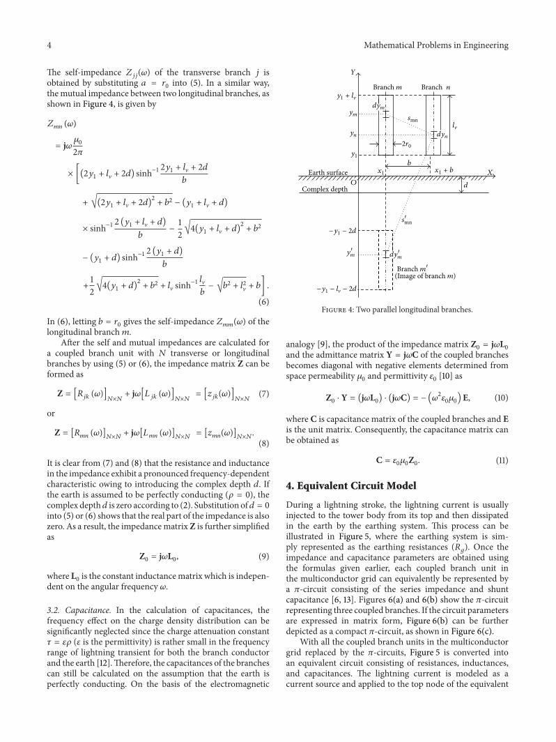
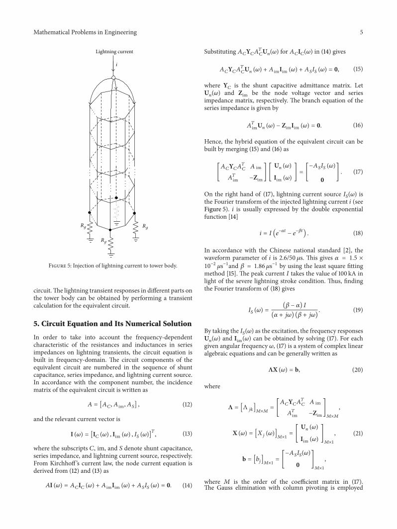
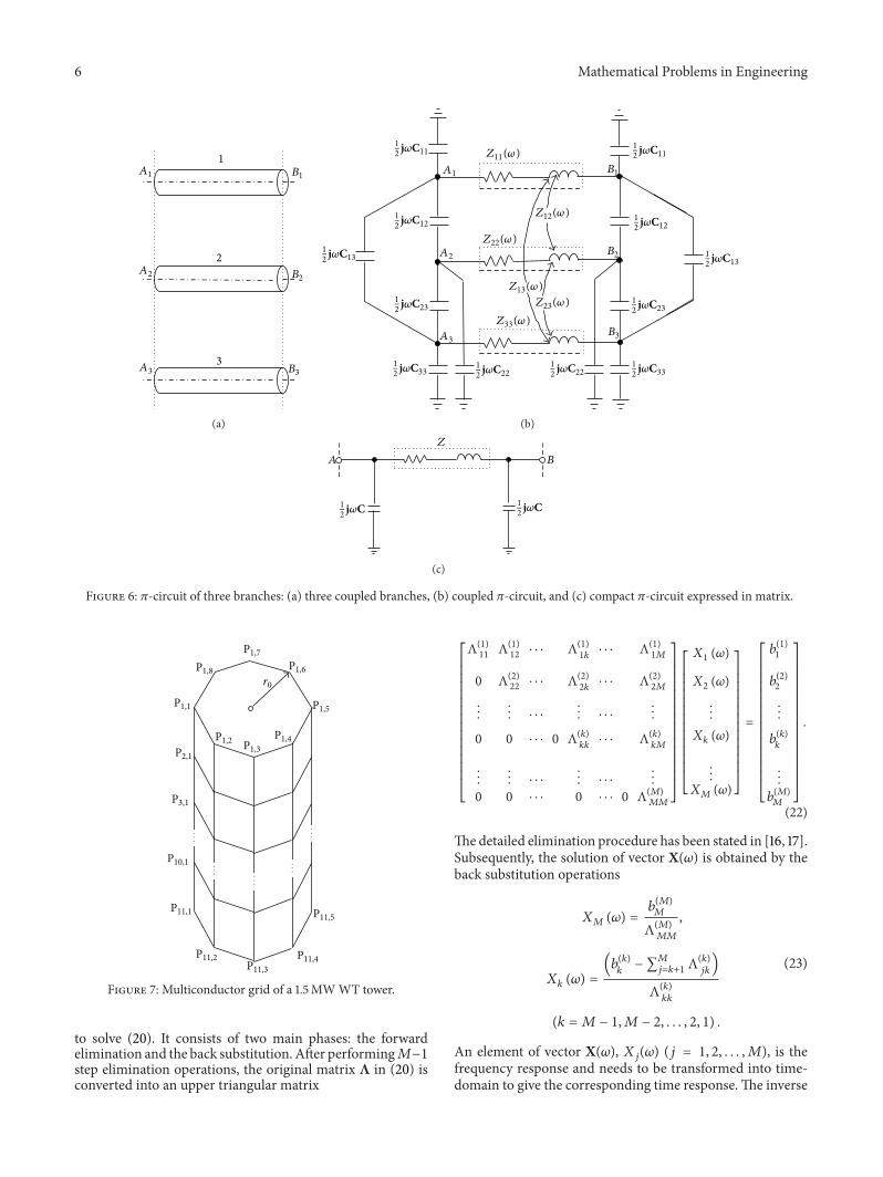
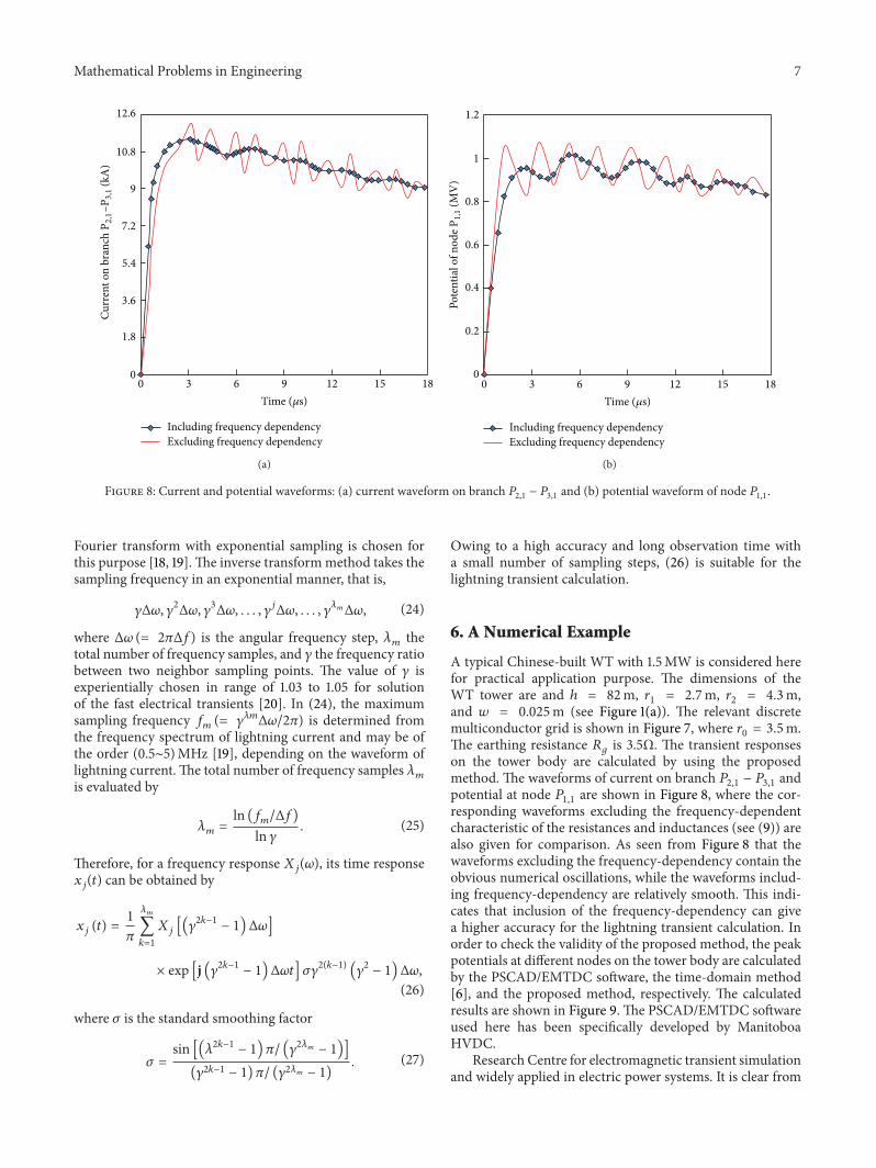


![Research Article An Algorithm for Evaluation of Lightning ...downloads.hindawi.com/journals/mpe/2014/925463.pdf · or substations [ , ]. is study considers the evaluation of electromagnetic](https://img.pdfslide.us/doc/110x75/5f767c11a2edd24b40366e56/research-article-an-algorithm-for-evaluation-of-lightning-or-substations-.jpg)