Embed Size (px)
Citation preview

Research ArticleAnalysis of Water Hammer with Different Closing Valve Laws onTransient Flow of Hydrogen-Natural Gas Mixture
Norazlina Subani and Norsarahaida Amin
Department of Mathematical Sciences Faculty of Science Universiti Teknologi Malaysia (UTM) 81310 Johor Bahru Johor Malaysia
Correspondence should be addressed to Norsarahaida Amin norsarahaidautmmy
Received 14 March 2015 Accepted 10 April 2015
Academic Editor Marco Donatelli
Copyright copy 2015 N Subani and N Amin This is an open access article distributed under the Creative Commons AttributionLicense which permits unrestricted use distribution and reproduction in any medium provided the original work is properlycited
Water hammer on transient flow of hydrogen-natural gas mixture in a horizontal pipeline is analysed to determine the relationshipbetween pressure waves and different modes of closing and opening of valves Four types of laws applicable to closing valve namelyinstantaneous linear concave and convex laws are considered These closure laws describe the speed variation of the hydrogen-natural gas mixture as the valve is closing The numerical solution is obtained using the reduced order modelling technique Theresults show that changes in the pressure wave profile and amplitude depend on the type of closing laws valve closure times and thenumber of polygonal segments in the closing function The pressure wave profile varies from square to triangular and trapezoidalshape depending on the type of closing laws while the amplitude of pressure waves reduces as the closing time is reduced and thenumbers of polygonal segments are increased The instantaneous and convex closing laws give rise to minimum and maximumpressure respectively
1 Introduction
Most analysis of flow in pipelines and networks has assumedthe flow to be at steady state conditions This means that theflow does not change with time at any location in the pipelinesystem With the assumption of uniform flow the analysisbecomes simpler and solutions are easy to obtain Study ontransient condition is important because pipeline flows arefrequently in unsteady state due to the sudden opening andclosing of valves All transient flows are transitions whetherin long or short duration Transient flow can be defined asthe flow fluctuation when the velocity and pressure of a fluidor gas flow change over time due to changes in the systemRelating specifically to pressure they are sometimes calleddynamic pressure changes or pressure transients
It is not feasible to prevent pressure transient whenoperating a piping system but this situation can be controlledThe main causes of transient flow conditions are closing oropening of valves in the piping system switching off thepower supply or a power failure andor equipment failureThe sudden closure of a control valve stopping of a pumpand variation of discharge due to pipeline rupture lead to
excess pressure in a pipeline [1]Wood et al [2] stated that thepressure transient results from an abrupt change in the flowvelocity and can be caused by main breaks sudden changesin demand or uncontrolled pump starting
When velocities in a pipe system change so rapidly thatthe elastic properties of the pipe and the liquid or gas mustbe examined in an analysis we have a hydraulic transientcommonly known as water hammer Water hammer is akind of transient phenomenon that occurs when rapid valveclosure suddenly blocks the flow in pipelines It depends onthe fluid compressibility where there are sudden changes inpressure Understanding water hammer is very importantin order to prevent excessive pressure buildup in pipelineswhich cause pipeline damage [3]
Pressure change in pipelines depends on gas velocityvalve closure time [4] and arrangement of the closing valveMaximum pressure can occur during valve closure or atthe end of the closure operation Therefore short timesduring valve closure are important in reducing themaximumpressure especially in emergency conditions Unfortunatelythis pressure transient is difficult to control because thisdamage is not always visible until long after the event
Hindawi Publishing CorporationAbstract and Applied AnalysisVolume 2015 Article ID 510675 12 pageshttpdxdoiorg1011552015510675
2 Abstract and Applied Analysis
Therefore valves are always installed in the pipeline to controlthe gas flow when damage occurs
According to Provenzano et al [5] there are fourmethodswhich can be used to modify the action of the valve (closurelaw) most commonly referred to as convex concave linearand instantaneous closing law These types of closing valvelaws represent a mathematical function that describes thespeed variation of the flow as it is closingThese types of valveclosure depend on the rate at which valves can be closedThevalve closure rate plays an important role in controlling thewater hammer phenomenon [1]
Valve closure times are also a source of risk when weanalyse the water hammer phenomenon Thus some effortshave been expended to optimize the time closure of controlvalves taking into account several kinds of restrictions Ghi-daoui et al [6] presented a general history and introductionof the water hammer phenomenon They stated that theproblem of water hammer was first studied by Menabrea [7]Michaud [8] examined the use of air chambers and safetyvalves for controllingwater hammer In the early 19th centurysome researchers attempted to develop expressions relating topressure and velocity changes in a pipe
Afshar et al [1] developed a closing rule curve for valvesin pipelines to control the water hammer impact Theypredicted the pressure increase and pipe discharge for avalve closing scenario in fluid flow The effect of differentparameters such as velocity viscosity and compressibilityof the pressure was investigated by Charles [9] Fouzi andAli [10] studied the effects of water hammer in hydraulicsystemsMansuri et al [11] also studied the sensitivity of somehydraulic parameters to water hammer problem These fourtypes of closure laws have been considered mostly in fluidsinvolving water but have not yet been applied in hydrogen-natural gas mixture
Elaoud and Hadj-Taıeb [12] studied the transient flow inhydrogen-natural gas mixture Studies on such problems areimportant because hydrogen is usually transported in thesame pipeline as natural gas to reduce transportation costand hydrogen is often stored together with natural gas toenhance its storage capability However they seemed to haveconsidered only the linear closing valve to determine therelationship between the mass ratio of mixture and pressure
According to Fouzi and Ali [10] analytical solutions arenot possible in the field of those who study the hydraulictransient Allievi [13] developed classical solutions for bothanalytical and graphical approaches Streeter [14] developeda numerical model by using a constant value of the turbulentfriction factorWiggert and Sundquist [15] solved the pipelinetransients using fixed grids projecting the characteristicsfrom outside the fundamental grid size Watt et al [16]provided a solution for rise of pressure by the method ofcharacteristics but transient friction has not been consideredChaudhry and Hussaini [17] solved the water hammer equa-tions by MacCormack Lambda and Gabutti explicit finitedifference schemes Pezzinga [18] and Elaoud andHadj-Taıeb[12] worked to evaluate the transient flow resistance by themethod of characteristics
Various numerical models including the Method ofCharacteristics (MOC) and Finite DifferenceMethod (FDM)
have been presented by different investigators to obtain thetransient pressure and discharge in water hammer situationsHowever these methods are time consuming especiallyfor gas network analysis More accurate results and lowercomputational costs are needed for the simulation of gasnetwork analysis Behbahani-Nejad and Shekari [19 20]proposed a Reduced Order Model (ROM) approach toachieve an efficient computational scheme for natural gastransient pipe flows ROMgave lower computational cost andreduced time for computation ROMwas recently used in theanalysis of unsteady flows [21] Agaie and Amin [22] usedthe ROM technique to study the effect of water hammer ontransportation of hydrogen-natural mixture They validatedthe Provenzano et al [5] problems to verify the accuracy ofROM
In the present study the water hammer phenomenon willbe solved by using this ROM on transient flow of hydrogen-natural gas mixture Our main objective is to determine therelationship between the pressure waves of hydrogen-naturalgas mixture with different modes of closing and opening ofvalves most commonly referred to as convex concave linearand instantaneous closing law To verify our objective thewater hammer on transient flow of hydrogen-natural gas isanalysed based on the types of closing laws closure valvetimes and the number of polygonal segments in the closingfunction
2 Mathematical Formulation
The mathematical models used to describe unsteady flowsof hydrogen-natural gas mixture in horizontal pipelines arepresented in the following
21 Governing Equation From the principle of conservationofmass andmomentum laws the governing equations for thetransportation of hydrogen-natural gas mixture in pipelinesare given by
120597120588
120597119905+ nabla sdot (120588V) = 0
120597 (120588V)120597119905
+ nabla sdot (120588119906V) = minusnabla119875 + nabla120591119908+ 120588F
(1)
where 120588 is defined as density V is vector velocity 119906 is gasvelocity 119875 is pressure 120591
119908is shear force and F is the net body
force per unit massFor a one-dimensional flow the continuity and momen-
tum equation under isothermal conditions can be written as
120597120588
120597119905+120597 (120588119906)
120597119909= 0 (2)
120597 (120588119906)
120597119905+120597 (1205881199062
)
120597119909= minus
120597119875
120597119909+ nabla120591119909+ 120588119891119909 (3)
where 120591119909is the shear force in the 119909-direction and 119891
119909is the net
body force per unit massUsing the hydraulic mean diameter 119863 the perimeter of
the pipe can be defined as 4119863 The shear force may be
Abstract and Applied Analysis 3
expressed in terms of the pipe friction coefficient 1198911015840 =
120591119909(12)120588119906
2 which can then be expressed as
120591119909= minus
1
21198911015840
1205881199062
times4
119863=21198911015840
1205881199062
119863 (4)
Substituting (4) into (3) the one-dimensional momen-tum equation in horizontal pipelines becomes
120597 (120588119906)
120597119905+120597 (1205881199062
)
120597119909= minus
120597119875
120597119909minus21198911015840
1205881199062
119863 (5)
According to Chaczykowski [23] the form of frictionfactor 211989110158401205881199062119863 where 1198911015840 = 1198914 is only used in theUnited Kingdom This friction factor 119891 is called the Fanningfriction factor which is defined as the ratio of the pipelinewallshear stress to the roughness of the pipe When this Fanningfriction factor is applied the momentum equation in (5) canalso be expressed as
120597 (120588119906)
120597119905+120597 (1205881199062
)
120597119909= minus
120597119875
120597119909minus1198911205881199062
2119863 (6)
The form of the friction term minus1198911205881199062
2119863 in (6) is morefrequently used in America and Europe However to ensurethat the frictional force shall always act opposite to thedirection of motion the momentum equation is written as
120597 (120588119906)
120597119905+120597 (1205881199062
+ 119875)
120597119909+119891120588119906 |119906|
2119863= 0 (7)
22 Equation of State For the isothermal flow in a pipelinethe gas properties can be assumed to be uniform or constantover any cross section in a pipeline It is known that the staticpressure may be assumed to be constant over a cross sectionof the pipeline Isothermal flow means that the gas remainsat the same temperature while flowing in a pipeline [24] Theequation of state for gas which is commonly used in the gasindustry is given by
119875
120588= 119885119877119879 (8)
where 119885 is the compressibility factor 119877 is the specific gasconstant and 119879 is the constant temperature
Usually the compressibility factor 119885 is assumed to beconstant too [20] Then the relation between the equation ofstate with celerity pressure wave 119888 is given by
119875 = 1205881198882
(9)
Themomentum equation (7) becomes written in terms ofthe celerity pressure wave
120597 (120588119906)
120597119905+120597 (1205881199062
+ 1205881198882
)
120597119909+119891120588119906 |119906|
2119863= 0 (10)
Therefore the continuity equation (2) and momentumequation (10) will be used in transient analysis of isothermalhydrogen-natural gas mixture in horizontal pipeline
23 Closing Valve Law Equation The closing valve law is amathematical function that describes the speed variation ofthe gas flow as it is closing [5] The derivative of (9) is takenand the subscript 119904 denotes the condition of constant entropygiven by
1198882
= (120597119875
120597120588)
119904
(11)
From (11) the relation of pressure and density to functionof 119905 and 119909 can be written as
120597120588
120597119905=1
1198882
120597119875
120597119905 (12a)
120597120588
120597119909=1
1198882
120597119875
120597119909 (12b)
Substituting (12a) and (12b) into (2) and (10) yields
120597119875
120597119905+ 1205881198882120597119906
120597119909= 0 (13a)
120597119906
120597119905+1
120588
120597119875
120597119909+119891119906 |119906|
2119863= 0 (13b)
Inmany cases on closing valve in pipes the friction factoris negligible because the value is very small Differentiatingequations (13a) and (13b) with respect to 119905 and 119909 respectivelygives
1205972
119875
1205971199052+ 1205881198882120597
120597119905(120597119906
120597119909) = 0 (14a)
120597
120597119909(120597119906
120597119905) +
1
120588
1205972
119875
1205971199092= 0 (14b)
Substituting (14a) and (14b) into one-dimensional waveequation gives the continuity and momentum equationwhich described the pattern of closing valve function as
1
1198882
1205972
119875
1205971199052= minus120588
120597
120597119905(120597119906
120597119909) (15a)
1205972
119875
1205971199092= minus120588
120597
120597119909(120597119906
120597119905) (15b)
24 Hydrogen-Natural Gas Mixture Equation For hydrogen-natural gas mixture the hydrogen mass ratio will be used indetermining the mixture density where the mass ratio of themixture is described as
120601 =119898ℎ
119898ℎ+ 119898119892
(16)
where 119898119892and 119898
ℎare defined as the mass of natural gas and
hydrogen respectivelyThe density of hydrogen and natural gas can be defined as
120588ℎ= 120588ℎ0(119875
1198750
)
1119899
(17a)
120588119892= 1205881198920(119875
1198750
)
11198991015840
(17b)
4 Abstract and Applied Analysis
where 120588ℎ0and 1205881198920are initial density of hydrogen and natural
gas respectively 119875 is transient pressure and 1198750is permanent
pressureThe expression of the average density of the mixture is
defined according to the mass ratio 120601 The density of thehydrogen-natural gas mixture then can be written as
120588 = [120601
120588ℎ
+(1 minus 120601)
120588119892
]
minus1
= [120601
120588ℎ0
(119875
1198750
)
1119899
+(1 minus 120601)
1205881198920
(119875
1198750
)
11198991015840
]
minus1
(18)
From (11) the celerity pressure wave of compressible gasflow can be expressed based on the hydrogen mass ratio Bytaking the derivative of (18) with respect to 119875 the celeritypressure wave (11) can be written as
119888 = [120601
120588ℎ0
(119875
1198750
)
1119899
+(1 minus 120601)
1205881198920
(119875
1198750
)
11198991015840
]
times [1
119875120601
119899120588ℎ0
(119875
1198750
)
1119899
+(1 minus 120601)
11989910158401205881198920
(119875
1198750
)
11198991015840
]
minus(12)
(19)
25 Closing Valve Function Provenzano et al [5] proposedthe following closing function
119906 (119905) = (1199060minus 119906120591) [1 minus (
119905
120591)
119898
] + 119906120591 (20a)
where 120591 = 119873119896 is the closing time 0 le 119898 lt infin and 119906120591is the
gas speed at the end of the closing valveThe closing time (120591) is stepped by a number of polygonal
segments in closing function denoted by 119896 given by
119906119894= (1199060minus 119906120591) [1 minus (
119894119896
120591)
119898
] + 119906120591 (20b)
where 0 le 119894 le 119873Equation (20b) allows finding the speed values at each of
the stepped times 119894119896
26 Boundary Conditions The boundary conditions at theinitial point 119909 = 0 are given by
119875 (0 119905) = 1198750(119905) (21a)
120588 (0 119905) = 1205880(119905) (21b)
120597119906
120597119909(0 119905) = 119906
0(119905) (21c)
where 1198750 1205880 and 119906
0are defined as pressure density and
velocity at the inlet pipeline respectivelyThe boundary conditions at the end point 119909 = 119871 are
120588119906 (119871 119905) = 120588119906119871(119905) (21d)
120597119875
120597119909(119871 119905) = 119875
119871(119905) (21e)
where 120588119906119871and 119875119871are defined as mass flux and pressure at the
outlet pipeline respectively
27 Initial Conditions The initial conditions at 119905 = 0 are
120597120588
120597119909(119909 0) = 0 (22a)
120597120588119906
120597119909(119909 0) = minus119888
2120597120588
120597119909minus119891120588119906 |119906|
2119863 (22b)
3 Numerical Solution
To solve numerically the governing equations (2) and (10)Reduced Order Model (ROM) is used The ROM is anefficient method to solve the transient hydrogen-natural gasmixture in a gas pipeline because of smaller number of errorsand reduced time consumption and computational cost
31 Transformation of Flux Vector Form The governingequations (2) and (10) can be written in the flux vector form
120597119876
120597119905+120597119864 (119876)
120597119909minus 119867 (119876) = 0 (23)
where
119876 = [120588
120588119906]
119864 (119876) = [120588119906
1205881199062
+ 1198882
120588]
119867 (119876) = [
[
0
minus119891120588119906 |119906|
2119863
]
]
(24)
32 Discretization of Implicit Steger Warming Flux VectorSplitting Scheme To construct ROM Implicit Steger Warm-ing Flux Vector Splitting Scheme (FSM) will be appliedFinite Difference Method (FDM) will be used to discretizeequation (23) and to obtain FSM scheme By using this FSMthe eigenvalue problem will be constructed from (23) Theresulting FSM scheme can be written as
minus [Δ119905
Δ119909119860119899(+)
119894minus1]Δ119876119894minus1+ [
Δ119905
Δ119909119860119899(minus)
119894+1]Δ119876119894+1
+ [119868 +Δ119905
Δ119909(119860119899(+)
119894minus 119860119899(minus)
119894) minus Δ119905119861
119899
119894]Δ119876119894
= minusΔ119905
Δ119909[119864119899(+)
119894minus 119864119899(+)
119894minus1+ 119864119899(minus)
119894+1minus 119864119899(minus)
119894] + Δ119905119867
119899
119894
(25)
33 Form of Eigenvalues Problem To perform the eigen-analysis and construct ROM it is necessary to linearizethe finite difference equation in (25) [19] The linearizationcan be achieved by assuming steady state in which stabilityperturbation is used to obtain the transient solution at eachnodal point
Abstract and Applied Analysis 5
For linearization the flow field variables at each time stepare given by
119876119899+1
= 1198760
+ 119876119899+1
(26)
where 1198760 represents the corresponding steady-state valuesand 119876 represents perturbation values
Substituting (26) into (25) yields
minus [Δ119905
Δ1199091198600(+)
119894minus1]119876119899+1
119894minus1+ [
Δ119905
Δ1199091198600(minus)
119894+1]119876119899+1
119894+1
+ [119868 +Δ119905
Δ119909(1198600(+)
119894minus 1198600(minus)
119894)]119876119899+1
119894minus Δ119905119861
0
119894119876119899+1
119894
= 119876119899
119894
(27)
Equation (27) can be simplified in the form of eigenvalueproblem
1198820
119876119899+1
= 119868119876119899
+ 119881119899+1
(28)
where 119881119899+1 = minus[(Δ119905Δ119909)1198600(+)
119894minus1]119876119899+1
119894minus1+ [(Δ119905Δ119909)119860
0(minus)
119894+1]119876119899+1
119894+1
and 119881 is defined as a vector consisting of the imposed valuesby the boundary conditions and1198820 represents the matrix
34 Construction of Reduced Order Model To construct theROM technique the zero eigenvalue in the eigensystem ofmatrix is required For zero forcing function 119881 we need toconsider the homogeneous part of (28) by setting
119876119894= 119909119894exp (119894120596
119894119905) 120572119894exp (119894119911
119894119909) (29)
where 120582119894is defined as eigenvalues 119909
119894is eigenvector and 119911
119894=
exp(120582119894Δ119905)
Then the diagonal matrix which contains the eigenvaluesand eigenvector can be written as
1199111198941198820
119909119894= 119868119909119894 (30)
In general (30) can be written as
119885119882119899
119883 = 119868119883 (31)
where 119885 represents the diagonal matrix of eigenvalue at eachtime step and 119883 is the matrix with column representing theright eigenvector
On the other hand the left eigenvectors satisfy thefollowing relation
(1198820
)119879
119884119885 = 119868119884 (32)
where 119884 is the matrix with rows that represent the lefteigenvector
If the eigenvectors are suitably normalized they satisfythe following orthogonality conditions
119884119879
119882119899
119883 = 119868
119884119879
119868119883 = 119885
(33)
35 Eigenmode Analysis For analysis of eigenmode basedon time (29) reduces the gas flow behavior to the sum ofindividual nodes
119876119894= 119909119894exp (120582
119894119905) (34)
Equation (34) can be written in general form as
119876 = 119883119888 (35)
where 119888 is the vector of normal node coordinateSubstituting (33) and (28) and thenmultiplying by119884119879 give
a set of119873 uncoupled equations for the nodal coordinates 119888
119888119899+1
= 119885119888119899
+ 119884119879
119881119899+1
(36)
Since the orthogonality conditions are satisfied the eigen-mode can be retained to construct ROM using (36)
4 Results and Discussion
Before analyzing the effect of different types of closing valvethe simple case of fluid (water) flow will be validated accord-ing to Provenzano et al [5] problem In the present studyROM is used as numerical method to solve the governingequations (2) and (10)This currentmethod is used to validatethe results
Figure 1 shows the results from the current methodcompared to those obtained by an analytical method Theresults obtained using ROM are in good agreement withthose of the analytical solution The effect of water hammeris observed at pressure oscillation at different types of closinglaws as plotted in Figure 1
41 Effect of Different Types of Closing Valve Case Study 1Four different types of closing valve laws are used to test theaccuracy of the solution in case of transient flow of hydrogen-natural gas mixture occurring in the pipeline
A single horizontal pipeline composed of a compressorpumping the mixture through an iron pipe and characterizedby a section of a pipeline system of 119871 = 500m length and119863 = 04m in diameter is illustrated in Figure 2 A rapidclosure valve (RCV) is placed at the downstreamendwhereasthe automatic closure valve (ACV) is placed at the immediatedischarged side of the compressor to avoid destruction of thecompressor [12]
Two parameters are used to characterize the dynamicresponse of the valves which are the reaction time andactuation time The reaction time is defined as the timetaken to start the valve actuation after sensing a pressureperturbation while the actuation time is the time intervalbetween the initial and the final positions of the valve Theactuation time is only considered for the RCV side
Four types of closing valve laws which are classified intoinstantaneous concave linear and convex are consideredFigure 3 shows the closing function corresponding to thedifferent types of closing valve with different mass ratioof hydrogen-natural gas mixture The 119898 exponent in (20a)determines the closing curve function as follows
6 Abstract and Applied Analysis
0 5 10 15 20 25 30 35
Provenzano et al (2011)Present method
minus1
minus08
minus06
minus04
minus02
0
02
04
06
08
1
(p(t)minusp0)p0
t (s)
(a) Instantaneous closing valve law (119898 = 0)
0 5 10 15 20 25 30minus1
minus08
minus06
minus04
minus02
0
02
04
06
08
1
Present methodProvenzano et al (2011)
(p(t)minusp0)p0
t (s)
(b) Concave closing valve law (119898 = 03)
0 5 10 15 20 25 30 35minus1
minus05
0
05
1
Provenzano et al (2011)Present method
(p(t)minusp0)p0
t (s)
(c) Linear closing valve law (119898 = 1)
0 5 10 15 20 25 30minus1
minus08
minus06
minus04
minus02
0
02
04
06
08
1
Provenzano et al (2011)Present method
(p(t)minusp0)p0
t (s)
(d) Convex closing valve law (119898 = 48)
Figure 1 Transient pressure waves for different types of closing valve laws (comparison present method (ROM) with analytical method) [5]
ACV RCV
CompressorL
Figure 2 Hydrogen-natural gas mixture installation [12]
Abstract and Applied Analysis 7
0 01 02 03 04 05 06 07 08 09 10
01
02
03
04
05
06
07
08
09
1
u(t)u0
Types of closing valve corresponding to different m values
t120591
m = 0
m = 005
m = 05
m = 1
m = 5
m = 50
Figure 3 Closing function corresponding to different values of119898 (from (20a))
119898 = 0 instantaneous closing0 le 119898 lt 1 concave closing119898 = 1 linear closing1 le 119898 lt infin convex closing
For instantaneous closing valve the gas flow speedchanges instantly to zero The speed of gas flow is reduceduniformly during the whole closing time when the linearclosing valve is applied Concave closing valve demonstratesrapid decrease of the speed flow at initial closing time andthen a slow reduction for most of the time whereas convexclosing valve features a low decrease of the speed flow duringthe early closing time which increases with time
Figure 4 shows plots of the numerically obtained resultsfor the pressure wave distribution as a function of time fordifferent values of the hydrogen mass ratio 120601 The numericalresults clearly show the interaction of the pressure wavegenerated by the types of closing valve The results of thenumerical simulation plotted in Figure 4 show that thepressure wave oscillation is repeated every 7 s for each typeof closing law
For instantaneous closing law the maximum pressurewave for hydrogen is 2006 bar for hydrogen-mixture (67)the maximum pressure wave is 2005 bar for hydrogen-mixture (33) the maximum pressure wave is 2003 bar andfor natural gas the maximum pressure wave is 2001 barFrom these numerical results the transient pressure wave ofhydrogen and hydrogen-natural gasmixture aremuch highercompared to natural gas For concave convex and linearclosing valves hydrogen has a maximum value of pressurewave compared to natural gas Instant closing valve producesthe minimum values of pressure waves compared to concaveconvex and linear closing valve
Figure 4 gives information on the pressure wave profileas a function of the closing valve The shape of pressurewave changes from square to trapezoidal for instantaneous
Table 1 Closure times [12]
Test ACV reaction (s) ACV actuation (s) RCV actuation (s)1 2 5 0252 02 05 02
closing law For concave closing law (0 lt 119898 lt 05)the pressure wave shape changes to trapezoidal When thevalue of 119898 increases (05 lt 119898 lt 1) the pressure waveshape is changed to triangular For linear closing law thepressurewave presented a strictly triangular form For convexclosing law (5 lt 119898 lt 50) the pressure wave changesfrom triangular towards the trapezoidal shape and becomespulse when (50 lt 119898 lt infin) This pulse wave is a kind ofnonsinusoidal wave form that is similar to a square wavebut does not have the symmetrical shape associated with aperfect square wave However increasing the values of119898willincrease the computation time and pressure wave
42 Effect of Closing Times Case Study 2 In case study 2the effects of the pressure change can be demonstrated byvarying the valve closure times [25] Two tests of differentvalve closure times are considered Table 1 summarizes theseclosure times
Figure 5 shows the effects of different valve closing timeson the transient pressure wave for hydrogen-natural gasmixture (33) Four different valves are considered for thepurpose of simulating the results The numerical resultsclearly show the interaction of the pressure wave generatedby RCV with the closure time of ACV [12] From the resultsplotted in Figure 5 the maximum value of the pressure waveis 2002 bar for Test 1 which is reached 025 s after the valveclosed instantly This higher pressure may be lowered byreducing the closure time which is represented by Test 2
8 Abstract and Applied Analysis
0 2 4 6 8 10 12 14 16 18 20199
1995
20
2005
201
Time (s)
Pres
sure
(bar
)
(a) Instantaneous closing valve law (119898 = 0)
0 2 4 6 8 10 12 14 16 18 20Time (s)
199
1995
20
2005
201
Pres
sure
(bar
)
(b) Concave closing valve law (119898 = 005)
0 2 4 6 8 10 12 14 16 18 20Time (s)
1985
199
1995
20
2005
201
2015
Pres
sure
(bar
)
(c) Concave closing valve law (119898 = 05)
0 2 4 6 8 10 12 14 16 18 20Time (s)
1975
198
1985
199
1995
20
2005
201
2015
202
Pres
sure
(bar
)
(d) Linear closing valve law (119898 = 1)
0 2 4 6 8 10 12 14 16 18 20Time (s)
Natural gasHydrogen mixture (33)Hydrogen mixture (67)
Hydrogen
1975
198
1985
199
1995
20
2005
201
2015
202
2025
Pres
sure
(bar
)
(e) Convex closing valve law (119898 = 5)
0 2 4 6 8 10 12 14 16 18 20Time (s)
Natural gasHydrogen mixture (33)Hydrogen mixture (67)
Hydrogen
minus200
minus100
0
100
200
300
400
500
600
Pres
sure
(bar
)
(f) Convex closing valve law (119898 = 50)
Figure 4 Transient pressure waves for different types of closing valve laws at different mass ratio
Abstract and Applied Analysis 9
0 2 4 6 8 10 12 14 16 18 20199
1995
20
2005
201
Time (s)
Pres
sure
(bar
)
(a) Instantaneous closing valve law (119898 = 0)
0 2 4 6 8 10 12 14 16 18 20199
1995
20
2005
201
Time (s)
Pres
sure
(bar
)
(b) Concave closing valve law (119898 = 05)
0 2 4 6 8 10 12 14 16 18 20199
1995
20
2005
201
Time (s)
Test 1Test 2
Pres
sure
(bar
)
(c) Linear closing valve law (119898 = 1)
0 2 4 6 8 10 12 14 16 18 2020
2005
201
2015
202
2025
Time (s)
Test 1Test 2
Pres
sure
(bar
)
(d) Convex closing valve law (119898 = 5)
Figure 5 Transient pressure waves as function of time 33 mass ratio of hydrogen-natural gas mixture
In this case the maximum value of the pressure wave isreduced to the value of 2001 bar which is reached in 225 safter the valve is closed For convex valve themaximumvalueof pressure wave for Test 1 is 2024 bar reached in 300 s afterthe valve closed and themaximum value of pressure wave forTest 2 is reduced to 2022 bar which is reached 100 s after thevalve is closed
However for concave and linear closing valve decreasingthe valve closing time shows an increasing pressurewave [25]For concave valve the maximum value of pressure wave ofTest 1 and Test 2 is 2003 bar and 2005 bar which reached600 s and 225 s respectively For linear valve the maximumvalue of pressure wave of Test 1 is 2008 bar at 005 s and
2009 bar at 225 s for Test 2 From the numerical resultsincreasing the values of119898 will increase the pressure wave forboth closing times Closing the valve instantly takes less timeto reduce the pressure compared to the convex closing lawthat takes more time to reduce the pressure
43 Effect of Number of Polygonal Segments in the ClosingFunction Case Study 3 For case study 3 the effect of numberof polygonal segments in the closing function has beenevaluated at different types of closing valves Three differentpolygonal segments denoted by 119896 (119896 = 2 4 10) have beentested to describe the profile and amplitude of pressure wavesat 33 of hydrogen-natural gas mixture
10 Abstract and Applied Analysis
0 2 4 6 8 10 12 14 16 18 201994
1996
1998
20
2002
2004
2006
Time (s)
Pres
sure
(bar
)
(a) Instantaneous closing valve law (119898 = 0)
0 2 4 6 8 10 12 14 16 18 201994
1996
1998
20
2002
2004
2006
Time (s)
Pres
sure
(bar
)
(b) Concave closing valve law (119898 = 05)
0 2 4 6 8 10 12 14 16 18 201985
199
1995
20
2005
201
2015
202
Time (s)
Pres
sure
(bar
)
k = 2
k = 4
k = 10
(c) Linear closing valve law (119898 = 1)
0 2 4 6 8 10 12 14 16 18 20199
1995
20
2005
201
2015
202
2025
Time (s)
Pres
sure
(bar
)
k = 2
k = 4
k = 10
(d) Convex closing valve law (119898 = 5)
Figure 6 Transient pressure waves and their polygonal approach for different 119896 segments at 33 of hydrogen-natural gas mixture
Figure 6 shows the closing valve function and its differentpolygonal segments From Figure 6 the patterns of pressurewave of hydrogen-natural gas mixture remain the same fordifferent number of segments at each type of closing law
Increasing the number of segments 119896 can reduce thepressure wave of hydrogen-natural gas mixture For concavevalve the minimum pressure wave at 119896 = 10 is 1995 barcompared to 119896 = 2 where the minimum pressure waveis 2000 bar The minimum pressure wave of linear valve is1989 bar and 2000 bar at 119896 = 10 and 119896 = 2 respectively
According to Provenzano et al [5] the closing valvemodel gets better asmore segments are included in the polyg-onal approach Increasing values of polygonal segments also
reduces the time to reach a minimum value of the pressurewave From the results plotted in Figure 6 the minimumtime taken to reach the minimum pressure of hydrogen-natural gas mixture is 061 s at 119896 = 10 (instantaneous closingvalve) compared to 110 s at 119896 = 2 for convex closing valve
5 Conclusion
The relationship between the pressure waves of hydrogen-natural gas mixture with the different types of closing valvelaws is determined based on the type of closing laws closuretimes and the polygonal segments of the closing functionThe different closing laws are analysed based on the different
Abstract and Applied Analysis 11
mass ratio of hydrogen-natural gasmixture using the reducedorder modelling technique The transient pressure waveincreases as the mass ratio of hydrogen is increased for eachtype of closing law
The instantaneous closing law (119898 = 0) gives the squareform of the pressure wave For concave closing law (0 le
119898 lt 1) the pressure wave shape changes from trapezoidal totriangular when 119898 increases For linear closing law (119898 = 1)the pressure wave is strictly in a triangular form For convexclosing valve (5 lt 119898 lt 50) the pressure wave changes fromtriangular towards trapezoidal shape Increasing the valueof 119898 increases the pressure wave and the time needed forcomputation It is found that the instantaneous closing lawgives rise to minimum pressure
The relationship between the pressurewaves of hydrogen-natural gasmixture (at 33of hydrogen content) with variousclosure times and different number of polygonal segments isalso determined The numerical results show the interactionof the transient pressure wave with the closure time generatedby RCV and ACV Reducing the closure time for both RCVand ACV reduces the transient pressure wave Closing thevalve instantly takes the least time to reduce the pressurewavewhile the convex closing law takes the longest time to do so
Increasing the values of polygonal segments denoted by 119896reduces the pressure wave and time to reach the minimumvalue The instantaneous closing law gives lowest pressurewhile the convex closing law produces themaximumpressurewavewhen the valve is closingThus to ensure the attainmentof minimum pressure within a short time the instantaneousclosing valve must be considered
It must be noted that to reduce the effects of waterhammer phenomenon devices and procedures such as valvemovement surge tanks and increased pipeline diametercould be considered to mitigate both high and low pressureand to reduce potential surge pressure [11 25]
Conflict of Interests
The authors declare that there is no conflict of interestsregarding the publication of this paper
Acknowledgment
Financial support provided by Vot 00M25 and Vot 01G31Research University Grant Scheme Universiti TeknologiMalaysia is gratefully acknowledged
References
[1] H Afshar R Kerachian M R Bazargan-Lari and A RNiktash ldquoDeveloping a closing rule curve for valves in pipelinesto control the water hammer impacts application of the NSGA-II optimization modelrdquo in Proceedings of the 7th InternationalPipelines Conference (IPC rsquo08) pp 1ndash10 American Society ofCivil Engineering Pipelines (ASCE) Atlanta Ga USA July2008
[2] D J Wood S Lingireddy B W Karney and D L McphersonldquoNumerical Methods for modelling transient flow in distribu-tion systemsrdquo Journal American Water Works Association vol97 no 7 pp 104ndash115 2005
[3] J-S Lee B-K KimW-R Lee and K-Y Oh ldquoAnalysis of waterhammer in pipelines by partial fraction expansion of transferfunction in frequency domainrdquo Journal of Mechanical Scienceand Technology vol 24 no 10 pp 1975ndash1980 2010
[4] B W Karney and E Ruus ldquoCharts for water hammer inpipelines resulting from valve closure from full opening onlyrdquoCanadian Journal of Civil Engineering vol 12 no 2 pp 241ndash2641985
[5] P G Provenzano F Baroni and R J Aguerre ldquoThe closingfunction in the water hammer modelingrdquo Latin AmericanApplied Research vol 41 no 1 pp 43ndash47 2011
[6] M S Ghidaoui M Zhao D A McInnis and D H AxworthyldquoA review of water hammer theory and practicerdquo AppliedMechanics Reviews vol 58 no 1 pp 49ndash76 2005
[7] L F Menabrea ldquoNote sur les effets du choc de lrsquoeau dansles conduitesrdquo Comptes Rendus Hebdomadaires des Seances delrsquoAcademie des Sciences vol 47 pp 221ndash224 1885
[8] J Michaud ldquoCoups de belier dans les conduites Etude desmoyens employes pour en atteneur les effectsrdquo Bulletin de laSociete Vaudoise des Ingenieurs et des Architectes vol 4 no 3-4 pp 56ndash64 65ndash77 1878
[9] B V Charles ldquoAnalysis of water hammer in pipes with non-condensable gasesrdquo in Proceedings of the AMSE Pressure Vesselsand Piping Division Conference (PVP rsquo09) Prague CzechRepublic 2009
[10] A Fouzi and F Ali ldquoComparative study of the phenomenon ofpropagation of elastic waves in conduitsrdquo in Proceedings of theWorld Congress on Engineering (WCE rsquo11) vol 3 London UK2011
[11] B Mansuri F Salmasi and B Oghati ldquoSensitivity analysis forwater hammer problem in pipelinesrdquo Iranica Journal of Energyand Environment vol 5 no 2 pp 124ndash131 2014
[12] S Elaoud and E Hadj-Taıeb ldquoTransient flow in pipelines ofhigh-pressure hydrogenndashnatural gas mixturesrdquo InternationalJournal of Hydrogen Energy vol 33 no 18 pp 4824ndash4832 2008
[13] L Allievi ldquoTheorie generale dumovement varie de lrsquoeau dans lestuyaux de conduitrdquoMechanical Review vol 14 pp 10ndash22 230ndash259 1904
[14] V L Streeter ldquoWater hammer analysisrdquo Journal of theHydraulicsDivision vol 95 no 6 1969
[15] D C Wiggert and M J Sundquist ldquoFixed grid characteristicsfor pipeline transientsrdquo Journal of Hydraulic ASCE vol 103 no12 pp 1403ndash1416 1977
[16] C S Watt J M Hobbs and A P Boldy ldquoHydraulic transientsfollowing valve closurerdquo Journal of Hydraulic ASCE vol 106 no1980 pp 1627ndash1640 1980
[17] M H Chaudhry and M Y Hussaini ldquoSecond-order accurateexplicit finite-difference schemes for water hammer analysisrdquoJournal of Fluids Engineering vol 107 no 4 pp 523ndash529 1985
[18] G Pezzinga ldquoEvaluation of unsteady flow resistances by quasi-2D or 1Dmodelsrdquo Journal of Hydraulic Engineering vol 126 no10 pp 778ndash785 2000
[19] M Behbahani-Nejad and Y Shekari ldquoThe accuracy and effi-ciency of a reduced-order model for transient flow analysis ingas pipelinesrdquo Journal of Petroleum Science and Engineering vol73 no 1-2 pp 13ndash19 2010
12 Abstract and Applied Analysis
[20] M Behbahani-Nejad and Y Shekari ldquoReduced order modellingof natural gas transient flow in pipelinesrdquo International Journalof Engineering and Applied Sciences vol 5 no 7 pp 148ndash1522008
[21] M Behbahani-Nejad H Haddadpour and V EsfahanianldquoReduced order modelling of unsteady flows without staticcorrection requirementrdquo in Proceedings of the 24th InternationalCongress of the Aeronautical Sciences (ICAS rsquo04) pp 1ndash8Yokohama Japan 2004
[22] B G Agaie and N Amin ldquoThe effect of water hammer onpressure oscillation of hydrogen natural gas transient flowrdquoApplied Mechanics and Materials vol 554 pp 251ndash255 2014
[23] M Chaczykowski ldquoTransient flow in natural gas pipelinemdashthe effect of pipeline thermal modelrdquo Applied MathematicalModelling vol 34 no 4 pp 1051ndash1067 2010
[24] J Zhou and M A Adewumi ldquoSimulation of transients innatural gas pipelines using hybrid TVD schemesrdquo InternationalJournal for Numerical Methods in Fluids vol 32 no 4 pp 407ndash437 2000
[25] H Garry B Susan and L Gregory ldquoPipeline surge analysisstudiesrdquo in Proceedings of the Pipeline Simulation Interest GroupAnnual Meeting (PSIG rsquo14) Baltimore Md USA 2014
Submit your manuscripts athttpwwwhindawicom
Hindawi Publishing Corporationhttpwwwhindawicom Volume 2014
MathematicsJournal of
Hindawi Publishing Corporationhttpwwwhindawicom Volume 2014
Mathematical Problems in Engineering
Hindawi Publishing Corporationhttpwwwhindawicom
Differential EquationsInternational Journal of
Volume 2014
Applied MathematicsJournal of
Hindawi Publishing Corporationhttpwwwhindawicom Volume 2014
Probability and StatisticsHindawi Publishing Corporationhttpwwwhindawicom Volume 2014
Journal of
Hindawi Publishing Corporationhttpwwwhindawicom Volume 2014
Mathematical PhysicsAdvances in
Complex AnalysisJournal of
Hindawi Publishing Corporationhttpwwwhindawicom Volume 2014
OptimizationJournal of
Hindawi Publishing Corporationhttpwwwhindawicom Volume 2014
CombinatoricsHindawi Publishing Corporationhttpwwwhindawicom Volume 2014
International Journal of
Hindawi Publishing Corporationhttpwwwhindawicom Volume 2014
Operations ResearchAdvances in
Journal of
Hindawi Publishing Corporationhttpwwwhindawicom Volume 2014
Function Spaces
Abstract and Applied AnalysisHindawi Publishing Corporationhttpwwwhindawicom Volume 2014
International Journal of Mathematics and Mathematical Sciences
Hindawi Publishing Corporationhttpwwwhindawicom Volume 2014
The Scientific World JournalHindawi Publishing Corporation httpwwwhindawicom Volume 2014
Hindawi Publishing Corporationhttpwwwhindawicom Volume 2014
Algebra
Discrete Dynamics in Nature and Society
Hindawi Publishing Corporationhttpwwwhindawicom Volume 2014
Hindawi Publishing Corporationhttpwwwhindawicom Volume 2014
Decision SciencesAdvances in
Discrete MathematicsJournal of
Hindawi Publishing Corporationhttpwwwhindawicom
Volume 2014 Hindawi Publishing Corporationhttpwwwhindawicom Volume 2014
Stochastic AnalysisInternational Journal of
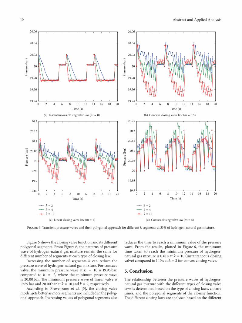


![DESIGN OF WATER HAMMER CONTROL STRATEGIES IN … · transient analysis. Hydraulic transient analysis is traditionally undertaken with deterministic models [2-3] that treat a number](https://img.pdfslide.us/doc/110x75/5fc1449eb026eb002f40d38b/design-of-water-hammer-control-strategies-in-transient-analysis-hydraulic-transient.jpg)


![arranged by tom wallace percussion by tony mccutchen 11 a a 10 aaa > e] aa aaa 6 aaa aaa aaa aaa aaa aaa 13 > 19 — 18 15 a a aa 16 a a 12 20 23 a > 24 aaa > 25 a > 26 aaa > 27 gÆ4k](https://img.pdfslide.us/doc/110x75/5e6c4dfc8bd84b079d5a5076/arranged-by-tom-wallace-percussion-by-tony-mccutchen-11-a-a-10-aaa-e-aa-aaa.jpg)