Embed Size (px)
Citation preview

Research ArticleA Three-Dimensional Finite Element Study onthe Biomechanical Simulation of Various Structured DentalImplants and Their Surrounding Bone Tissues
Gong Zhang,1 Hai Yuan,1 Xianshuai Chen,1 Weijun Wang,1 Jianyu Chen,2
Jimin Liang,1 and Peng Zhang3
1Guangzhou Institute of Advanced Technology, Chinese Academy of Sciences, Guangzhou 511458, China2Hospital of Stomatology, Sun Yat-sen University Hospital, Guangzhou 510000, China3Foshan Stomatology Hospital, Foshan 528000, China
Correspondence should be addressed to Gong Zhang; [email protected]
Received 5 August 2015; Revised 20 November 2015; Accepted 15 December 2015
Academic Editor: Natasa N. Jakoba
Copyright © 2016 Gong Zhang et al. This is an open access article distributed under the Creative Commons Attribution License,which permits unrestricted use, distribution, and reproduction in any medium, provided the original work is properly cited.
Background/Purpose. This three-dimensional finite element study observed the stress distribution characteristics of 12 types ofdental implants and their surrounding bone tissues with various structured abutments, implant threads, and healingmethods underdifferent amounts of concentrated loading.Materials andMethods. A three-dimensional geometrical model of a dental implant andits surrounding bone tissue was created; the model simulated a screw applied with a preload of 200N or a torque of 0.2N⋅m and aprosthetic crown applied with a vertical or an inclined force of 100N. The Von Mises stress was evaluated on the 12 types of dentalimplants and their surrounding bone tissues. Results. Under the same loading force, the stress influence on the implant threadswas not significant; however, the stress influence on the cancellous bone was obvious. The stress applied to the abutment, corticalbone, and cancellous bone by the inclined force applied to the crown was larger than the stress applied by the vertical force to thecrown, and the abutment stress of the nonsubmerged healing implant systemwas higher than that of the submerged healing implantsystem. Conclusion. A dental implant system characterised by a straight abutment, rectangle tooth, and nonsubmerged healing mayprovide minimum value for the implant-bone interface.
1. Introduction
Since osseointegrated dental implants are introduced for therehabilitation of the edentulous patient in the late 1960s, atremendous awareness and subsequent demand have beenarising in the field [1–3]. Recently, dental implants have beenincreasingly applied in oral rehabilitation and orthopedicsused as replacements after the natural teeth are lost orpartially damaged, which could restore human masticationfunctions [4]. Previous studies showed that dental implanta-tion could have a high success rate: retention rate is in excessof 95% over a 5-year period if dental implants were correctlydesigned, manufactured, and inserted [5–7].
However, dental implant treatments are still failing fre-quently. One of the major causes of failure is that an artificial
implant may never function as perfectly as the living tissuesit replaces.
As a matter of fact, the success of dental implant isstrongly affected by a number of biomechanical factors,including the type of loading, material properties of implantand prosthesis, implant geometry, surface structure, qualityand quantity of surrounding bone, nature of implant-boneinterface, and surgical procedures [8]. As far as implantshape is concerned, main design parameters affecting loadtransfer mechanisms include implant diameter and lengthof implant-bone interface [9], as well as thread pitch, shape,and depth in the case of threaded implants [10, 11]. Inconsideration of increasing surfaces appointed for osseousintegration, threaded implants are generally preferred tosmooth cylindrical ones [12].
Hindawi Publishing CorporationInternational Journal of DentistryVolume 2016, Article ID 4867402, 9 pageshttp://dx.doi.org/10.1155/2016/4867402

2 International Journal of Dentistry
The use of screw-type implants increases contact area andimproves implant stability [13]. Other designs, such as thestepped implant and the tapered body of threaded implant,have also been proposed to mimic the root anatomy and toenhance the bony support in spongy bone, thereby creatinga favorable load distribution [14, 15]. In addition, the threadsize, thread profile, and surface roughness may affect thestress pattern in the surrounding bone [16–18].
Otherwise, occlusal loading may often be applied to animplant within 48 h after implant placement [19]. Neverthe-less, the effectiveness of an immediately loaded implant isless predictable than that of the delay-loaded implant [20].The main concern is the occurrence of fibrous encapsulationinstead of osseointegration around implants [21].
The objective of this research is to compare the biome-chanical effects of the immediately loaded dental implantsand the surrounding bone tissue with various abutments(straight and angled), implant threads (trapezia tooth, rect-angle tooth, and saw tooth), and healing methods (sub-merged and nonsubmerged) using a three-dimensional finiteelement analysis, accounting for the interaction betweenthe dental implants and the supporting bone tissues. Threecontact models and four types of loading conditions areused to simulate different integration qualities at the implant-bone interface during the osseointegration process. Extensivenumerical simulation results show the influences of com-positional profile, occlusal force orientations, and preloadtypes on the static and dynamic behavior of the implant/bonesystem.
2. Materials and Methods
2.1. CAD Modeling. The three-dimensional geometricalmodel of the dental implant (Figure 1) and surroundingbone system (shown in Figure 2) was created using the CADsoftware Unigraphics NX 4.0 (Siemens PLM Software Inc.,Germany). The geometry of the adult mandible took theshape created fromCTdatabase through image segmentationand spline reconstruction with STP format [24].
The dental implant/supporting bone system comprisedabutment, an implant, an internal screw connecting theabutment and implant, and prosthetic crown duplicated fromthe molar, surrounding cortical bone and cancellous bone inthe mandibular section (Figure 3).
As shown in Figure 4, the abutments were divided intostraight abutment (shorted for “St”) and angled abutment(shorted for “An”), respectively.Themaximum diameter was5.1mm, wearing gingiva length was 5mm, and the inclinedangle of angled abutment was 15∘ (Straumann Product Cata-log 2012, Straumann AG, Switzerland).
In dentistry, platform switching was a method used topreserve alveolar bone levels around dental implants. Anarrower abutment diameter for a given implant platformdiameter was used [25].
The diameter and length of the implant were 4.1mmand 14mm, respectively (Straumann Product Catalog 2012,Straumann AG, Switzerland). Figure 5 illustrated externalthread of the implant comprising trapezia tooth shorted for“Tr” (pitch P was 0.6mm, thread depth was 0.5P, and thread
Abutment
Implant
Figure 1: Dental implant system.
Cancellous bone
Cortical bone
Figure 2: Surrounding bone tissues.
angle was 30∘), rectangle tooth shorted for “Re” (pitch P was0.6mm, thread depth is 0.5P, and thread angle was 0∘), andsaw tooth shorted for “Sa” (pitch P is 0.6mm, thread depthwas 0.75P, face flank angle was 3∘, and nonface flank anglewas 30∘).
In the connection of the implant and the abutment,we adopted internal hexagon and Morse taper. Figure 6depicted two healing methods of submerged one shorted for“Su” (smooth neck height was 1.2mm) and nonsubmergedone shorted for “Ns” (smooth neck height was 1.2mm, theinclination anglewas 15∘, and total heightwas 2.0mm) (Strau-mann Product Catalog 2012, Straumann AG, Switzerland).
According to the various structured abutments, implantthreads, and healing methods, 12 combinations of the dentalimplant systems were exhibited (Figure 7 and Table 1).
2.2. Finite Element Modeling. All 12 models described abovewere combined using Boolean operations, and the para-solid format of the solid model was then imported intoANSYS Workbench 14.0 (ANSYS, Inc., USA) to generate theFE model (Figure 8) using 10-node tetrahedral ℎ-elements(ANSYS SOLID187 elements).
The convergence of the FEM analysis depended largelyon the mesh grid. A standard convergence study was con-ducted by FEM analysis for mesh grids with different meshrefinement levels. A refined mesh was used in the threadedareas and the surrounding bone. For mesh grid, the relativeerrors for the maximum Von Mises stress in the implantsystem and the surrounding bone were computed as the

International Journal of Dentistry 3
Table 1: 12 combinations of the dental implant systems.
Category Abutment Implant Healing Nodes1# “St” “Tr” “Su” 124,1282# “St” “Re” “Su” 123,6763# “St” “Sa” “Su” 123,6844# “St” “Tr” “Ns” 123,0605# “St” “Re” “Ns” 123,2946# “St” “Sa” “Ns” 124,4337# “St” “Tr” “Su” 129,2028# “An” “Re” “Su” 128,9949# “An” “Sa” “Su” 129,57810# “An” “Tr” “Ns” 127,70611# “An” “Re” “Ns” 128,93812# “An” “Sa” “Ns” 128,721St: straight; An: angled; Tr: trapezia; Re: rectangle; Sa: saw; Su: submerged;Ns: nonsubmerged.
Crown
Abutment
Implant
Cancellous bone
Cortical bone
Screw
Figure 3: Dental implant/bone system.
percent differences between the current stress values andtheir counterparts predicted by the previous trial run. Thecalculation was considered to be convergent and the meshgrid was accepted when the relative errors were less than 1%.Number of total nodes is listed in Table 1, respectively.
2.3. Materials and Load Conditions. The abutment, implant,screw, cortical bone, and cancellous bone were treated asisotropic homogeneous linear elastic materials. Table 2 listedYoung’s modulus (𝐸), Poisson’s ratio (𝜐), and Tensile Strength(Ts) of thematerials used in the numerical examples. Becausethe elements were quite small, the material properties wereassumed to be constant within each element.
The bottom of the mandible was treated as fixed bound-aries, and both side planes were frictionless, which wasnormal constraint (Figure 9). Two different contact models(“bonded” and “frictional”) are used to simulate differentintegration qualities at the implant and the supportingbone tissues during the osseointegration process. Usingcontact type of frictional to describe the integration qualityamong the abutment, implant, and screw interface andamong implant, cortical bone, and cancellous bone interface
(Table 3), the friction coefficient was 0.5 and 0.4, respec-tively [26]. Frictional contact implied that a gap betweenthe implant and the peri-implant part might exist underan occlusal force. The rest of the contact surfaces wereBonded contact (Table 3). The “bonded” type simulatedperfect osseointegration in which the implant and the sur-rounding parts were fully integrated so that neither slidingnor separation in the implant-bone interface was possible.
Based on oral physiology, four types of loading conditions(Figure 6) were simulated:
(1) A vertical occlusal force of 100N (𝜃 = 0) applied onthe crown top surface [4], a preload of 200N appliedto the screw [27].
(2) A vertical occlusal force of 100N (𝜃 = 0) applied onthe crown top surface [4], a torque of 0.2N⋅m appliedto the screw [27].
(3) An inclined occlusal force of 100N (𝜃= 15∘) applied onthe crown top surface [4], a preload of 200N appliedto the screw [27].
(4) An inclined occlusal force of 100N (𝜃= 15∘) applied onthe crown top surface [4], a torque of 0.2N⋅m appliedto the screw [27].
3. Results
Figure 7 gave the VonMises stress distributions of the typicaldental implants and the surrounding bone tissues underloading condition (1), (2), (3), or (4), respectively.
As shown in Figure 10, the stress wasmainly concentratedat the inner hexagon positioning junction because the forcewas just applied only on the contact surface. Application ofthe preload or torque applied to the screw resulted in thestress concentration on the screw, and fatigue failure wouldoccur in the process of long-term use. The stresses in thecortical bone and cancellous bone, which were conjoint withimplant, were relatively small due to the design concept ofplatform switching, which could reduce the stresses graduallyat junction between the implant and the surrounding bonetissues, thus avoiding bone level being decreased in the long-term use.
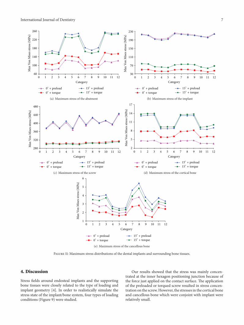
Then we compared the maximum Von Mises stress dis-tributions of 12 types of the dental implants and surroundingbone tissues (Figure 11).
Figure 11(a) exhibited the stress distribution of the abut-ment. When vertical force was applied on the crown, theabutment stress of the torque applied to the screw was largerthan that of the preload condition while in the inclined forcethe abutment stress of the preload applied to the screw waslarger than that of the torque condition. Both in the preloadand in torque condition, the abutment stress of the inclinedforce was significantly higher than that in the vertical force ofthe crown. Taken together, the abutment maximum stressesof 1#, 2#, 3#, 7#, 8#, and 9# were rather small.
Figure 11(b) presented stress distribution of the implant.In the preloaded screw application, the stress differencewas small in both the vertical force and the inclined forceconditions. In the torque condition, the implant stress in

4 International Journal of Dentistry
Table 2: Material properties used in this study.
Material Region E (MPa) 𝜐 Ts (MPa) ReferenceTitanium Implant, abutment, screw 102,000 0.35 485 [22]Porcelain Crown 68,900 0.28 835 [22]Cortical bone Mandible 13,000 0.30 133.9 [23]Cancellous bone Mandible 690 0.30 56 [23]
Table 3: Contact methods.
Abutment Screw Implant Cortical bone Cancellous boneCrown Bonded — — — —Abutment — Frictional Frictional — —Screw — — Frictional — —Implant — — — Frictional FrictionalCortical bone — — — — Bonded
(a) Straight abutment (b) Angled abutment
Figure 4: Abutment category.
(a) Trapezia tooth (b) Rectangle tooth (c) Saw tooth
Figure 5: Thread category of the implant.
the inclined force was larger than that in the vertical force.Both in the vertical and the inclined force, the preloadedapplication had great effect on the implant stress. Takentogether, the implantmaximum stresses of 3#, 4#, 5#, 10#, and11# were rather small.
Figure 11(c) depicted the stress distribution of the screw.Whether in the preloaded or in torque application, the verti-cal and inclined force of the crown application had little effecton screw stress. However, under same loading conditions, thescrew stress of the preloaded screw had greater effect than the

International Journal of Dentistry 5
(a) Submerged (b) Nonsub-merged
Figure 6: Healing method.
1# 2# 3# 4# 5# 6# 7# 8# 9# 10# 11# 12#
Figure 7: 3D model of 12 dental implant systems.
Figure 8: Finite element mesh view.
torque one. Taken together, the screw maximum stresses of1#, 3#, 5#, 7#, 9#, and 11# were rather small.
Figure 11(d) represented the stress distribution of thecortical bone. The cortical bone stress was relatively small.Whether in the preload or in torque application of the screw,the cortical bone stress of the inclined force was larger thanthe vertical force while in the vertical force the torquedscrew application had greater effect on screw stress than thepreloaded one. However, in the inclined force application,the torqued screw had smaller effect on screw stress thanthe preload condition. Taken together, the cortical bone
maximum stresses of 4#, 5#, 6#, 10#, 11#, and 12# were rathersmall.
Figure 11(e) showed the stress distribution of the cancel-lous bone. The cancellous bone stress was relatively small.Whether in the preload or in torque application of thescrew, the cancellous bone stress of the inclined force waslarger than that of the vertical force. However, under sameload conditions, the preloaded screw had greater effect onscrew stress than the torque condition. Taken together, thecancellous bone maximum stresses of 4#, 5#, 6#, 9#, 10#, and11# were rather small.

6 International Journal of Dentistry
Force
Fixed
Frictionless
Preload/torque
𝜃
Figure 9: Load conditions of dental implant-bone tissue.
84.57 Max75.375
66.18
56.984
47.789
38.593
29.398
20.202
11.007
1.8115 Min
217.59 Max193.47
169.36
145.25
121.13
97.017
72.902
48.788
24.673
0.55868 Min
374.87 Max333.48
292.09
250.7
209.31
167.92
126.52
85.132
43.74
2.3486 Min
3.2396 Max2.8801
2.5205
2.161
1.8015
1.4419
1.0824
0.72289
0.36336
0.0038265 Min
4.579 Max4.0702
3.5615
3.0527
2.5439
2.0351
1.5264
1.0176
0.50881
3.9464e − 5 Min(a) Straight abutment, trapezia tooth, and submerged healing under loading condition (1)
142.86 Max127.08
111.3
95.519
79.738
63.956
48.175
32.393
16.612
0.83033 Min
43.47 Max38.654
33.838
29.022
24.206
19.39
14.574
9.7578
4.9417
0.12565 Min
303.05 Max269.53
236.02
202.5
168.99
135.47
101.96
68.442
34.927
1.4119 Min
1.6924 Max1.5048
1.3172
1.1296
0.94204
0.75444
0.56684
0.37924
0.19164
0.0040372 Min
5.7812 Max5.1388
4.4965
3.8541
3.2118
2.5694
1.9271
1.2847
0.64237
1.2292e − 5 Min(b) Straight abutment, rectangular tooth, and nonsubmerged healing loading condition (2)
181.51 Max161.53
141.56
121.59
101.61
81.639
61.665
41.692
21.718
1.7443 Min
213.9 Max190.17
166.43
142.69
118.96
95.222
71.486
47.75
24.015
0.27871 Min
399.65 Max355.52
311.39
267.26
223.12
178.99
134.86
90.73
46.598
2.4663 Min
30.047 Max26.709
23.371
20.033
16.695
13.357
10.018
6.6802
3.342
0.0038453 Min
13.26 Max11.787
10.314
8.8403
7.3669
5.8935
4.4202
2.9468
1.4734
1.9825e − 5 Min(c) Angled abutment, saw tooth, and submerged healing under loading condition (3)
243.2 Max216.3
189.39
162.49
135.58
108.68
81.775
54.87
27.966
1.0609 Min
60.906 Max54.155
47.403
40.652
33.901
27.149
20.398
13.647
6.8955
0.14421 Min
317.46 Max282.24
247.03
211.82
176.61
141.39
106.18
70.968
35.756
0.54331 Min
3.2777 Max2.914
2.5504
2.1867
1.823
1.4594
1.0957
0.73207
0.36841
0.0047473 Min
9.6504 Max8.5782
7.5059
6.4336
5.3614
4.2891
3.2168
2.1446
1.0723
2.2425e − 5 Min
(d) Angled abutment, rectangular tooth, and nonsubmerged healing under loading condition (4)
Figure 10: Stress distributions in the typical dental implants and the surrounding bone tissues.
International Journal of Dentistry 7
60
100
140
180
220
260
0 1 2 3 4 5 6 7 8 9 10 11 12
Max
Von
Mise
s stre
ss (M
Pa)
Category
0∘+ preload
0∘+ torque
15∘+ preload
15∘+ torque
(a) Maximum stress of the abutment
30
70
110
150
190
230
0 1 2 3 4 5 6 7 8 9 10 11 12
Max
Von
Mise
s stre
ss (M
Pa)
Category
0∘+ preload
0∘+ torque
15∘+ preload
15∘+ torque
(b) Maximum stress of the implant
280
320
360
400
440
480
0 1 2 3 4 5 6 7 8 9 10 11 12
Max
Von
Mise
s stre
ss (M
Pa)
Category
0∘+ preload
0∘+ torque
15∘+ preload
15∘+ torque
(c) Maximum stress of the screw
2
5
8
11
14
17
0 1 2 3 4 5 6 7 8 9 10 11 12
Max
Von
Mise
s stre
ss (M
Pa)
Category
0∘+ preload
0∘+ torque
15∘+ preload
15∘+ torque
(d) Maximum stress of the cortical bone
1
2
3
4
5
6
0 1 2 3 4 5 6 7 8 9 10 11 12
Max
Von
Mise
s stre
ss (M
Pa)
Category
0∘+ preload
0∘+ torque
15∘+ preload
15∘+ torque
(e) Maximum stress of the cancellous bone
Figure 11: Maximum stress distributions of the dental implants and surrounding bone tissues.
4. Discussion
Stress fields around endosteal implants and the supportingbone tissues were closely related to the type of loading andimplant geometry [4]. In order to realistically simulate thestress state of the implant/bone system, four types of loadingconditions (Figure 9) were studied.
Our results showed that the stress was mainly concen-trated at the inner hexagon positioning junction because ofthe force just applied on the contact surface. The applicationof the preloaded or torqued screw resulted in stress concen-tration on the screw.However, the stresses in the cortical boneand cancellous bone which were conjoint with implant wererelatively small.

8 International Journal of Dentistry
Table 4: Stress comparisons of 12 implants-bone tissues.
Dental implant-bone systemAbutment Implant Screw Cortical bone Cancellous bone Frequency
Implant combinations
1# + + 22# + 13# + + + 34# + + + 35# + + + + 46# + + 27# + + 28# + 19# + + 210# + + 211# + + + 312# + + 2
The symbol of “+” meant the unit with minimum stress of the implant-bone tissues.
Under same loading direction of the crown, the stressinfluence on the torqued screw was greater than that of thepreload condition in the abutment and cortical bone whilethe stress influence of the preloaded screw was greater thanthat of the torqued condition for the implant, screw, andcancellous bone.The reason was mainly that the torque actedon the upper inner surface of the hexagonal hole of the screwwhile the preloadwas applied to the lower outer surface of thescrew.
Meanwhile, under same loading mode of the screw,the stress distributions of the abutment, cortical bone, andcancellous bone in the inclined force on the crown werelarger than those in the vertical force, up to 2 to 3 times.However, as for the implant and screw, the stress influencewith different loading direction applied on the crown wasnot large. It was mainly due to the fact that the vertical forcemade stress distribution of the surrounding bone uniformthrough the cross section and the thread of implant. Whilethe inclined force generated shear force and bendingmomenton the implant, thus the stress concentration at the implant’sneck and bone contact area has taken place.
In addition, the abutment stress of nonsubmergedimplant was larger than that of the submerged one undersame load conditions. However, the implant, cortical bone,and cancellous bone stresses of nonsubmerged implant weresmaller than those of submerged one indicating that if anoverload condition occurred during chewing, the abutmentof nonsubmerged system and the implant of submergedsystem would be susceptible to be broken, which could affectthe long-term retention rate of the implant system.Therefore,doctors and patients need to take certain protective measuresin use.
Table 4 listed stress distributions of 12 combinations of thedental implants and surrounding bone tissues (The symbol of“+” meant the unit with minimum stress of the implant-bonetissues). It was seen from Table 4 that 5# was the best option,which was the straight abutments, rectangular tooth, andnonsubmerged dental implant system. Meanwhile, 3#, 4#,and 11# were also provided with a certain application value.
5. Conclusion
Under same loading conditions, the thread had no significanteffect on the implant stress but a greater impact on the can-cellous bone stress. The stress distributions of the abutment,cortical bone, and cancellous bone in the inclined force ofthe crown were larger than that in the vertical force. Theabutment stress of nonsubmerged healing implant systemwas larger than that of the submerged healing one. However,the implant, cortical bone, and cancellous bone stresses ofnonsubmerged implant system were smaller than those ofsubmerged one.
In conclusion, a dental implant system characterised bya straight abutment, rectangular tooth, and nonsubmergedhealing method is the optimal design.
Conflict of Interests
The authors declare that there is no conflict of interestsregarding the publication of this paper.
Acknowledgments
Financial support from theNationalNatural Science Founda-tion of China (51307170), the Cooperation Project of ChineseAcademy of Sciences and Foshan City Government of China(2014HT10008), the Guangzhou City Key Laboratory project(15180003), and the Guangzhou Nansha District High-TechIndustrialization Project of China (201202005) is gratefullyacknowledged.
References
[1] H. Iplikcioglu and K. Akca, “Comparative evaluation of theeffect of diameter, length and number of implants supportingthree-unit fixed partial prostheses on stress distribution in thebone,” Journal of Dentistry, vol. 30, no. 1, pp. 41–46, 2002.
[2] R. Adell, B. Eriksson, U. Lekholm, P. I. Branemark, and T. Jemt,“Long-term follow-up study of osseointegrated implants in the
International Journal of Dentistry 9
treatment of totally edentulous jaws,”The International Journalof Oral &Maxillofacial Implants, vol. 5, no. 4, pp. 347–359, 1990.
[3] R. Adell, U. Lekholm, B. Rockler, and P. I. Branemark, “A 15-year study of osseointegrated implants in the treatment of theedentulous jaw,” International Journal of Oral Surgery, vol. 10,no. 6, pp. 387–416, 1981.
[4] J. Yang and H.-J. Xiang, “A three-dimensional finite elementstudy on the biomechanical behavior of an FGBM dentalimplant in surrounding bone,” Journal of Biomechanics, vol. 40,no. 11, pp. 2377–2385, 2007.
[5] R. Calandriello andM. Tomatis, “Immediate occlusal loading ofsingle lower molars using br anemark system(R) wide platformTiUnite implants: a 5-year follow-up report of a prospec-tive clinical multicenter study,” Clinical Implant Dentistry andRelated Research, vol. 19, pp. 381–396, 2009.
[6] G. O. Gallucci, C. B. Doughtie, J. W. Hwang, J. P. Fiorellini, andH.-P.Weber, “Five-year results of fixed implant-supported reha-bilitations with distal cantilevers for the edentulous mandible,”Clinical Oral Implants Research, vol. 20, no. 6, pp. 601–607, 2009.
[7] F. E. Lambert,H.-P.Weber, S.M. Susarla,U.C. Belserand, andG.O. Gallucci, “Descriptive analysis of implant and prosthodonticsurvival rates with fixed implant-supported rehabilitations inthe edentulous maxilla,” Journal of Periodontology, vol. 80, no.8, pp. 1220–1230, 2009.
[8] J. B. Brunski, “Biomechanics of dental implants,” in Implants inDentistry, M. Block, J. N. Kent, and L. R. Guerra, Eds., no. 2, pp.63–71, W.B. Saunders, Philadelphia, Pa, USA, 1997.
[9] T. Li, K. Hu, L. Cheng et al., “Optimum selection of thedental implant diameter and length in the posterior mandiblewith poor bone quality—A 3D finite element analysis,” AppliedMathematical Modelling, vol. 35, no. 1, pp. 446–456, 2011.
[10] C.-C. Lee, S.-C. Lin, M.-J. Kang, S.-W.Wu, and P.-Y. Fu, “Effectsof implant threads on the contact area and stress distributionof marginal bone,” Journal of Dental Sciences, vol. 5, no. 3, pp.156–165, 2010.
[11] H.-L. Huang, C.-H. Chang, J.-T. Hsu, A.M. Fallgatter, and C.-C.Ko, “Comparison of implant body designs and threaded designsof dental implants: a 3-dimensional finite element analysis,”International Journal of Oral andMaxillofacial Implants, vol. 22,no. 4, pp. 551–562, 2007.
[12] C. E. Misch and M. W. Bidez, “A scientific rationale for dentalimplant design,” in Contemporary Implant Dentistry, C. E.Misch, Ed., pp. 329–343, Mosby, St. Louis, Mo, USA, 2ndedition, 1999.
[13] N. Sykaras, A. M. Iacopino, V. A. Marker, R. G. Triplett,and R. D. Woody, “Implant materials, designs, and surfacetopographies: their effect on osseointegration. A literaturereview,” International Journal ofOral andMaxillofacial Implants,vol. 15, no. 5, pp. 675–690, 2000.
[14] C. Maiorana and F. Santoro, “Maxillary and mandibular bonereconstruction with hip grafts and implants using Frialit-2implants,” International Journal of Periodontics and RestorativeDentistry, vol. 22, no. 3, pp. 221–229, 2002.
[15] G. H. Nentwig, “Ankylos implant system: concept and clinicalapplication,” Journal of Oral Implantology, vol. 30, no. 3, pp. 171–177, 2004.
[16] S. Hansson and M. Werke, “The implant thread as a retentionelement in cortical bone: the effect of thread size and threadprofile: A finite element study,” Journal of Biomechanics, vol. 36,no. 9, pp. 1247–1258, 2003.
[17] L. Kong, K. Hu, D. Li et al., “Evaluation of the cylinder implantthread height and width: a 3-dimensional finite element anal-ysis,” International Journal of Oral and Maxillofacial Implants,vol. 23, no. 1, pp. 65–74, 2008.
[18] H.-L. Huang, J.-T. Hsu, L.-J. Fuh, D.-J. Lin, and M. Y. C. Chen,“Biomechanical simulation of various surface roughnesses andgeometric designs on an immediately loaded dental implant,”Computers in Biology and Medicine, vol. 40, no. 5, pp. 525–532,2010.
[19] D. L. Cochran, D. Morton, and H.-P. Weber, “Consensusstatements and recommended clinical procedures regardingloading protocols for endosseous dental implants,” InternationalJournal of Oral andMaxillofacial Implants, vol. 19, no. 5, pp. 109–113, 2004.
[20] C. E. Misch, H.-L. Wang, C. M. Misch, M. Sharawy, J. Lemons,and K. W. M. Judy, “Rationale for the application of immediateload in implant dentistry: part I,” Implant Dentistry, vol. 13, no.3, pp. 207–217, 2004.
[21] R. Gapski, H.-L.Wang, P.Mascarenhas, andN. P. Lang, “Criticalreview of immediate implant loading,” Clinical Oral ImplantsResearch, vol. 14, no. 5, pp. 515–527, 2003.
[22] J. Chen, X. Lu, N. Paydar, H. U. Akay, and W. E. Roberts,“Mechanical simulation of the human mandible with and with-out an endosseous implant,” Medical Engineering and Physics,vol. 16, no. 1, pp. 53–61, 1994.
[23] J. Y. Rho, R. B. Ashman, and H. Turner, “Young’s modulus oftrabecular and cortical bone material: ultrasonic and microten-sile measurements,” Journal of Biomechanics, vol. 26, no. 2, pp.111–119, 1993.
[24] A. N. Natali, P. G. Pavan, and A. L. Ruggero, “Analysis ofbone-implant interaction phenomena by using a numericalapproach,” Clinical Oral Implants Research, vol. 17, no. 1, pp. 67–74, 2006.
[25] Y. Maeda, J. Miura, I. Taki, and M. Sogo, “Biomechanicalanalysis on platform switching: is there any biomechanicalrationale?” Clinical Oral Implants Research, vol. 18, no. 5, pp.581–584, 2007.
[26] Z. Enwei andG. Fei, “Analysis of static force and fatigue betweenthread structure of dental implant and contact surface,” Journalof Clinical Rehabilitative Tissue Engineering, vol. 14, no. 30, pp.5531–5534, 2010.
[27] C. Luo, “Effects of different shape of occlusal screws on stabilityfor single implant-supported crowns,” Chinese Journal of OralImplantology, vol. 14, no. 2, pp. 44–47, 2009.

Submit your manuscripts athttp://www.hindawi.com
Hindawi Publishing Corporationhttp://www.hindawi.com Volume 2014
Oral OncologyJournal of
DentistryInternational Journal of
Hindawi Publishing Corporationhttp://www.hindawi.com Volume 2014
Hindawi Publishing Corporationhttp://www.hindawi.com Volume 2014
International Journal of
Biomaterials
Hindawi Publishing Corporationhttp://www.hindawi.com Volume 2014
BioMed Research International
Hindawi Publishing Corporationhttp://www.hindawi.com Volume 2014
Case Reports in Dentistry
Hindawi Publishing Corporationhttp://www.hindawi.com Volume 2014
Oral ImplantsJournal of
Hindawi Publishing Corporationhttp://www.hindawi.com Volume 2014
Anesthesiology Research and Practice
Hindawi Publishing Corporationhttp://www.hindawi.com Volume 2014
Radiology Research and Practice
Environmental and Public Health
Journal of
Hindawi Publishing Corporationhttp://www.hindawi.com Volume 2014
The Scientific World JournalHindawi Publishing Corporation http://www.hindawi.com Volume 2014
Hindawi Publishing Corporationhttp://www.hindawi.com Volume 2014
Dental SurgeryJournal of
Drug DeliveryJournal of
Hindawi Publishing Corporationhttp://www.hindawi.com Volume 2014
Hindawi Publishing Corporationhttp://www.hindawi.com Volume 2014
Oral DiseasesJournal of
Hindawi Publishing Corporationhttp://www.hindawi.com Volume 2014
Computational and Mathematical Methods in Medicine
ScientificaHindawi Publishing Corporationhttp://www.hindawi.com Volume 2014
PainResearch and TreatmentHindawi Publishing Corporationhttp://www.hindawi.com Volume 2014
Preventive MedicineAdvances in
Hindawi Publishing Corporationhttp://www.hindawi.com Volume 2014
EndocrinologyInternational Journal of
Hindawi Publishing Corporationhttp://www.hindawi.com Volume 2014
Hindawi Publishing Corporationhttp://www.hindawi.com Volume 2014
OrthopedicsAdvances in


![INDEX [microdentsystem.com] · 2015-11-24 · INDEX PRESENTATION. INTRODUCTION MULTIPLE PROSTHESIS. REMOVABLE AND IMMEDIATE PROSTHESIS. SINGLE PROSTHESIS CEMENTED PROSTHESIS. Microdent](https://img.pdfslide.us/doc/110x75/5facd9ee77a5ed547a36b19c/index-2015-11-24-index-presentation-introduction-multiple-prosthesis-removable.jpg)