Embed Size (px)
Citation preview
Hindawi Publishing CorporationMathematical Problems in EngineeringVolume 2013, Article ID 863104, 8 pageshttp://dx.doi.org/10.1155/2013/863104
Research ArticleA Simple Generation Technique of Complex GeotechnicalComputational Model
Hang Lin,1,2 Taoying Liu,1 Jiangteng Li,1 and Ping Cao1
1 School of Resources and Safety Engineering, Central South University, Changsha, Hunan 410083, China2 State Key Laboratory of Coal Resources and Safe Mining, China University of Mining and Technology, Xuzhou, Jiangsu 221116, China
Correspondence should be addressed to Hang Lin; [email protected]
Received 27 November 2012; Accepted 7 January 2013
Academic Editor: Fei Kang
Copyright © 2013 Hang Lin et al.This is an open access article distributed under the Creative CommonsAttribution License, whichpermits unrestricted use, distribution, and reproduction in any medium, provided the original work is properly cited.
Given that FLAC3D (a geotechnical calculation software) is difficult to use for building large, complex, and three-dimensionalmining models, the current study proposes a fast and a convenient modeling technique that combines the unique advantagesof FLAC3D in numerical calculation and those of SURPAC (a mine design software) in three-dimensional modeling, and theinterface program was compiled. First, the relationship between the FLAC3D and the SURPAC unit data was examined, and thetransformation technique between the data was given. Then, the interface program that transforms the mine design model tocalculate the model was compiled using FORTRAN, and the specific steps of the program implementation were described using alarge iron and copper mine modeling example.The results show that the proposed transformation technique and its correspondinginterface program transformed the SURPAC model into the FLAC3D model, which expedited FLAC3D modeling, verified thevalidity and feasibility of the transformation technique, and expanded the application spaces of FLAC3D and SURPAC.
1. Introduction
Along with the rapid development of computer technologyin recent years, the numerical method along with artificialintelligence technique has become an important mean ofanalyzing and calculating modern engineering technologies[1–6] and forecasting engineering stability and reliability [5,7–9]. FLAC3D (numerical calculation software) has beenextensively recognized and applied for analyzing geotechnicalissues [10–12]. FLAC3D could be used to examine thechanging rules of the field effect of rock mass from themacrotrend and it is suitable for most engineeringmechanicsissues, particularly for analyzing material elastoplasticity,large deformation, rheology prediction, and for geotechni-cal numerical simulation of construction processes [13–16].However, FLAC3D is quite difficult to use for pretreatmentmodeling, particularly in the geological body of complicatedmultimedia and multiboundaries [17, 18]. Thus, engineersoften usemodels by simplifications to approximately describegeotechnical models to solve this problem above. But differ-ent lithologies have different mechanical features excessivesimplification of the model would reduce the reliability
of the numerical simulation results. On the other hand,the geology or mine design platform demonstrates goodthree-dimensional modeling, and it could accurately expressthe spatial distribution of the stratum and the geologicalstructure with different lithologies [19–22]. A great progresshas been made on simulation methods of complex geologicalinterfaces and features, for instance, Xu et al. [17] suggesteda 3D geological modeling technique (SGM) as a tool forconstructing complex geological models in rock engineering,Wu and Xu [23] used a simple plane to simulate the faultor multiple combined planes to approximate the fault, formodeling geological faults in 3D, and Zhong et al. [24] pre-sented an integrated 3D geological modeling methodologyfor modeling and visualization of large 3D geoengineeringapplications. But mine design is relatively independent ofnumerical calculation and analysis, and its function is gener-ally limited to visualization and qualitative judgments. Thus,combining the advantages of the mine design platform inmodeling and that of FLAC3D in numerical calculation andanalysis is necessary. Recently, only few studies have beenconducted on this combination.
2 Mathematical Problems in Engineering
The numerical calculation of a large mining project ofteninvolves complicated three-dimensional geological models.The current study takes the mine design software SUR-PAC with its powerful modeling function as the platform,builds complex three-dimensional models of mines, andautomatically generates a FLAC3D model through datatransformation to expand the application of FLAC3D intothe numerical simulation of mine projects to solve thedifficulties of FLAC3Dmodeling and to build accurate three-dimensional mining models that can improve the reliabilityof simulation results and give play to the computationalpower of FLAC3D. Moreover, SURPAC could also expand itsmechanical analytical ability based on its inherent functionssuch as data collection, storage, management, and inquiry tomeet the requirements of an engineeringmodel in predictionand decision support.
2. Development of the ModelTransformation Procedure
2.1. SURPAC Modeling. The SURPAC serial software is a setof megadigitized mining engineering software with domesticleading level in minefields, and it is extensively applied toresource appraisal, geological measurement, mine designplan, production plan management, and reclamation designafter pit closure [25–27]. Moreover, SURPAC could helpmetal mines to effectively achieve digitization and informati-zation of mine design, planning, and management. SURPAChas a complete set of three-dimensional modeling tools,and it could achieve complete imaging of mine exploration,three-dimensional geological modeling, the establishment ofengineering database, open gallery and underground minedesign, production and mining progress plans, tailing, andreclamation designs. Moreover, SURPAC has a powerfulthree-dimensional graphic system, and its core is composedof a totally integrated graphic module that has a complete setof visualization means and of data editing tools that visuallygenerates and displays the three-dimensional structures ofunderground geology or mining areas, ground and terrainmodels, and other graphics. Moreover, it is an effective,convenient, and fast platform for building complex compu-tational models.
SURPAC adopts a polygon mesh to describe the physicalborders of an orebody that forms during extraction, and blockmodeling is performed after the solid model is built. Thesolidmodel is a three-dimensional geometricmodel based oncomputer geometric shaping technologies, and it completelydescribes the spatial structure, geometric configuration, andspatial borderline of the lithology. A block, model includes athree-dimensional model consisting of common hexahedralblocks and it is the foundation for lithologic assignment andthe subsequent numerical calculation. The basic idea is todivide the spatial geometric model of the orebody into amultitude of unit blocks and then to assign lithology valuesto the unit blocks that fill the entire orebody.
2.2. Brief Description of FLAC3D. FLAC3D is a numeri-cal modeling code for advanced geotechnical analysis of
2
2
6
6
4
4
3
3
1
1
5
58
7
𝑠1
𝑠2
𝑠3
Face
Figure 1: Data relationship between FLAC3D and SURPAC unitdata.
soil, rock, and structural support in three dimensions [28].FLAC3D is used in analysis, testing, and design by geotech-nical, civil, and mining engineers. It is designed to accom-modate any kind of geotechnical engineering project, wherecontinuum analysis is necessary.
FLAC3D utilizes an explicit finite difference formulationthat can model complex behaviors not readily suited to FEMcodes, such as problems that consist of several stages, largedisplacements and strains, and nonlinear material behaviorandunstable systems (even the cases of yield/failure over largeareas or total collapse).
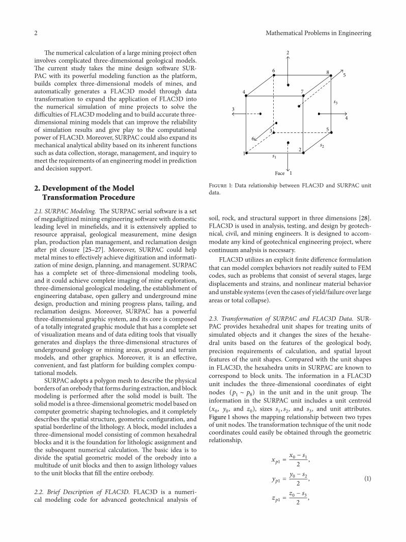
2.3. Transformation of SURPAC and FLAC3D Data. SUR-PAC provides hexahedral unit shapes for treating units ofsimulated objects and it changes the sizes of the hexahe-dral units based on the features of the geological body,precision requirements of calculation, and spatial layoutfeatures of the unit shapes. Compared with the unit shapesin FLAC3D, the hexahedra units in SURPAC are known tocorrespond to block units. The information in a FLAC3Dunit includes the three-dimensional coordinates of eightnodes (𝑝
1∼ 𝑝8) in the unit and in the unit group. The
information in the SURPAC unit includes a unit centroid(𝑥0, 𝑦0, and 𝑧
0), sizes 𝑠
1, 𝑠2, and 𝑠
3, and unit attributes.
Figure 1 shows the mapping relationship between two typesof unit nodes.The transformation technique of the unit nodecoordinates could easily be obtained through the geometricrelationship,
𝑥𝑝1=𝑥0− 𝑠1
2,
𝑦𝑝1=𝑦0− 𝑠2
2,
𝑧𝑝1=𝑧0− 𝑠3
2,
(1)
Mathematical Problems in Engineering 3
34
0
6
2
0
353032
3337
7
Root
0 1 2 4 5 6 3 7
30 31 32 33 34 35 36 37
Figure 2: Unit subdivision.
where, 𝑥𝑝1, 𝑦𝑝1, and 𝑧
𝑝1represent the 𝑥, 𝑦, and 𝑧 coordinates
of point 𝑝1, respectively.
The three-dimensional coordinates of points 𝑝2∼ 𝑝8
could be obtained using the same theory.Parts in the model that need special treatment are
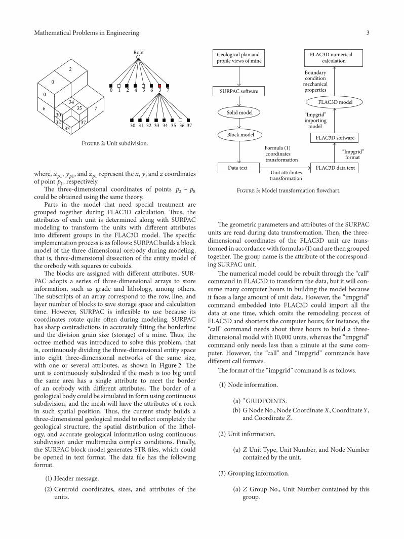
grouped together during FLAC3D calculation. Thus, theattributes of each unit is determined along with SURPACmodeling to transform the units with different attributesinto different groups in the FLAC3D model. The specificimplementation process is as follows: SURPAC builds a blockmodel of the three-dimensional orebody during modeling,that is, three-dimensional dissection of the entity model ofthe orebody with squares or cuboids.
The blocks are assigned with different attributes. SUR-PAC adopts a series of three-dimensional arrays to storeinformation, such as grade and lithology, among others.The subscripts of an array correspond to the row, line, andlayer number of blocks to save storage space and calculationtime. However, SURPAC is inflexible to use because itscoordinates rotate quite often during modeling. SURPAChas sharp contradictions in accurately fitting the borderlineand the division grain size (storage) of a mine. Thus, theoctree method was introduced to solve this problem, thatis, continuously dividing the three-dimensional entity spaceinto eight three-dimensional networks of the same size,with one or several attributes, as shown in Figure 2. Theunit is continuously subdivided if the mesh is too big untilthe same area has a single attribute to meet the borderof an orebody with different attributes. The border of ageological body could be simulated in form using continuoussubdivision, and the mesh will have the attributes of a rockin such spatial position. Thus, the current study builds athree-dimensional geological model to reflect completely thegeological structure, the spatial distribution of the lithol-ogy, and accurate geological information using continuoussubdivision under multimedia complex conditions. Finally,the SURPAC block model generates STR files, which couldbe opened in text format. The data file has the followingformat.
(1) Header message.(2) Centroid coordinates, sizes, and attributes of the
units.
SURPAC software
Solid model
Block model
Data text
coordinates transformation
Unit attributestransformation
FLAC3D data text
format
FLAC3D software
importingmodel
FLAC3D model
FLAC3D numerical calculation
Geological plan and profile views of mine
Boundarycondition
mechanicalproperties
“Impgrid”
“Impgrid”Formula (1)
Figure 3: Model transformation flowchart.
The geometric parameters and attributes of the SURPACunits are read during data transformation. Then, the three-dimensional coordinates of the FLAC3D unit are trans-formed in accordance with formulas (1) and are then groupedtogether. The group name is the attribute of the correspond-ing SURPAC unit.
The numerical model could be rebuilt through the “call”command in FLAC3D to transform the data, but it will con-sume many computer hours in building the model becauseit faces a large amount of unit data. However, the “impgrid”command embedded into FLAC3D could import all thedata at one time, which omits the remodeling process ofFLAC3D and shortens the computer hours; for instance, the“call” command needs about three hours to build a three-dimensional model with 10,000 units, whereas the “impgrid”command only needs less than a minute at the same com-puter. However, the “call” and “impgrid” commands havedifferent call formats.
The format of the “impgrid” command is as follows.
(1) Node information.
(a) ∗GRIDPOINTS.(b) GNodeNo., Node Coordinate𝑋, Coordinate𝑌,
and Coordinate 𝑍.
(2) Unit information.
(a) 𝑍 Unit Type, Unit Number, and Node Numbercontained by the unit.
(3) Grouping information.
(a) 𝑍 Group No., Unit Number contained by thisgroup.
4 Mathematical Problems in Engineering
NN
N
N
in number 1 central mining area
in number 1 central mining area in number 1 central mining area
in number 1 central mining area
in number 2 central mining area
in number 1 central mining area in number 1 central mining area
480 sections worked out area
400 sections worked out area
in main mining area
in main mining area
460 sections worked out area in main mining area
440 sections worked out area in main mining area
420 sections worked out area in main mining area
675 sections worked out area
580 sections worked out area 560 sections worked out area
625 sections worked out area645 sections worked out area 605 sections worked out area
480 sections worked out area
in number 2 central mining area 540 sections worked out area
in number 2 central mining area 560 sections worked out area
in number 2 central mining area 590 sections worked out area
in number 2 central mining area 500 sections worked out area
in number 2 central mining area 520 sections worked out area
NN
Figure 4: AUTOCAD plan view.
Based on the analysis of unit data relationship above,the current study uses FORTRAN to compile the inter-face program. First, the program transforms the data intothe required data format. Then, the program calls in thedata using the “impgrid” command of FLAC3D, and then
it sums the boundary condition, initial condition, anddynamic parameters of the soil body for calculations. Referto Figure 3 for specific procedures. However, the modeltransferred from SURPAC can not make sure the gridof element meets each other, then the command “attach
Mathematical Problems in Engineering 5
480 m main460 m main440 m main420 m main400 m main
1–605 m1–580 m
1–675 m
1–645 m1–625 m
1–605 m
2–590 m
2–560 m2–540 m
2–480 m
2–520 m2–500 m
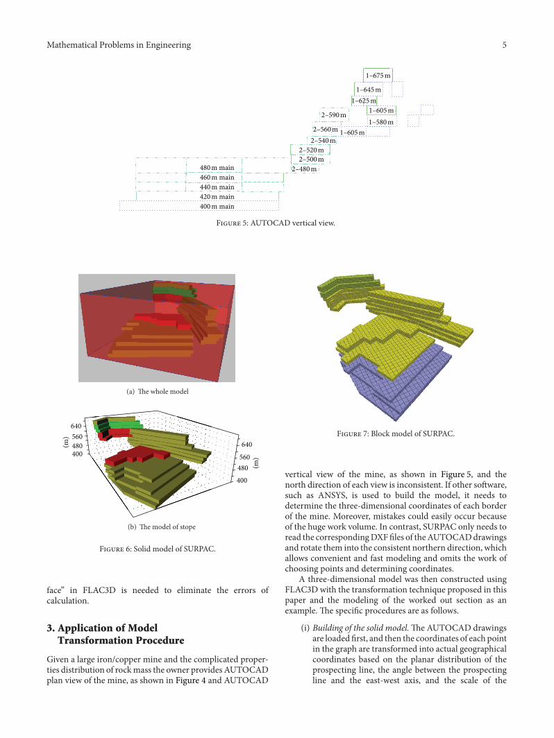
Figure 5: AUTOCAD vertical view.
(a) The whole model
640560480400
(m)
(m)
640
560480
400
(b) The model of stope
Figure 6: Solid model of SURPAC.
face” in FLAC3D is needed to eliminate the errors ofcalculation.
3. Application of ModelTransformation Procedure
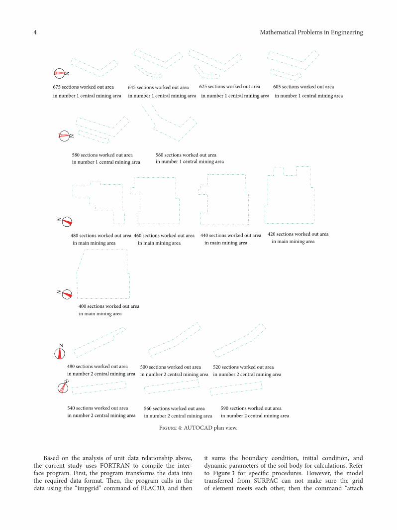
Given a large iron/copper mine and the complicated proper-ties distribution of rockmass the owner provides AUTOCADplan view of the mine, as shown in Figure 4 and AUTOCAD
Figure 7: Block model of SURPAC.
vertical view of the mine, as shown in Figure 5, and thenorth direction of each view is inconsistent. If other software,such as ANSYS, is used to build the model, it needs todetermine the three-dimensional coordinates of each borderof the mine. Moreover, mistakes could easily occur becauseof the huge work volume. In contrast, SURPAC only needs toread the correspondingDXFfiles of theAUTOCADdrawingsand rotate them into the consistent northern direction, whichallows convenient and fast modeling and omits the work ofchoosing points and determining coordinates.
A three-dimensional model was then constructed usingFLAC3D with the transformation technique proposed in thispaper and the modeling of the worked out section as anexample. The specific procedures are as follows.
(i) Building of the solid model.TheAUTOCAD drawingsare loaded first, and then the coordinates of each pointin the graph are transformed into actual geographicalcoordinates based on the planar distribution of theprospecting line, the angle between the prospectingline and the east-west axis, and the scale of the
6 Mathematical Problems in Engineering
(a) The whole model
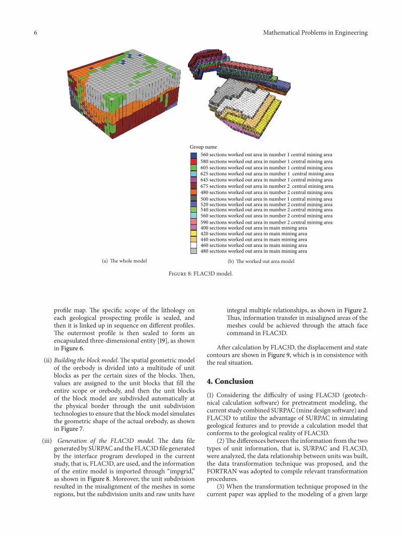
Group name560 sections worked out area in number 1 central mining area580 sections worked out area in number 1 central mining area605 sections worked out area in number 1 central mining area625 sections worked out area in number 1 central mining area645 sections worked out area in number 1 central mining area
520 sections worked out area in number 2 central mining area540 sections worked out area in number 2 central mining area560 sections worked out area in number 2 central mining area590 sections worked out area in number 2 central mining area
480 sections worked out area in number 2 central mining area
400 sections worked out area in main mining area420 sections worked out area in main mining area440 sections worked out area in main mining area460 sections worked out area in main mining area480 sections worked out area in main mining area
675 sections worked out area in number 2 central mining area
500 sections worked out area in number 1 central mining area
(b) The worked out area model
Figure 8: FLAC3D model.
profile map. The specific scope of the lithology oneach geological prospecting profile is sealed, andthen it is linked up in sequence on different profiles.The outermost profile is then sealed to form anencapsulated three-dimensional entity [19], as shownin Figure 6.
(ii) Building the block model.The spatial geometric modelof the orebody is divided into a multitude of unitblocks as per the certain sizes of the blocks. Then,values are assigned to the unit blocks that fill theentire scope or orebody, and then the unit blocksof the block model are subdivided automatically atthe physical border through the unit subdivisiontechnologies to ensure that the blockmodel simulatesthe geometric shape of the actual orebody, as shownin Figure 7.
(iii) Generation of the FLAC3D model. The data filegenerated by SURPAC and the FLAC3Dfile generatedby the interface program developed in the currentstudy, that is, FLAC3D, are used, and the informationof the entire model is imported through “impgrid,”as shown in Figure 8. Moreover, the unit subdivisionresulted in the misalignment of the meshes in someregions, but the subdivision units and raw units have
integral multiple relationships, as shown in Figure 2.Thus, information transfer in misaligned areas of themeshes could be achieved through the attach facecommand in FLAC3D.
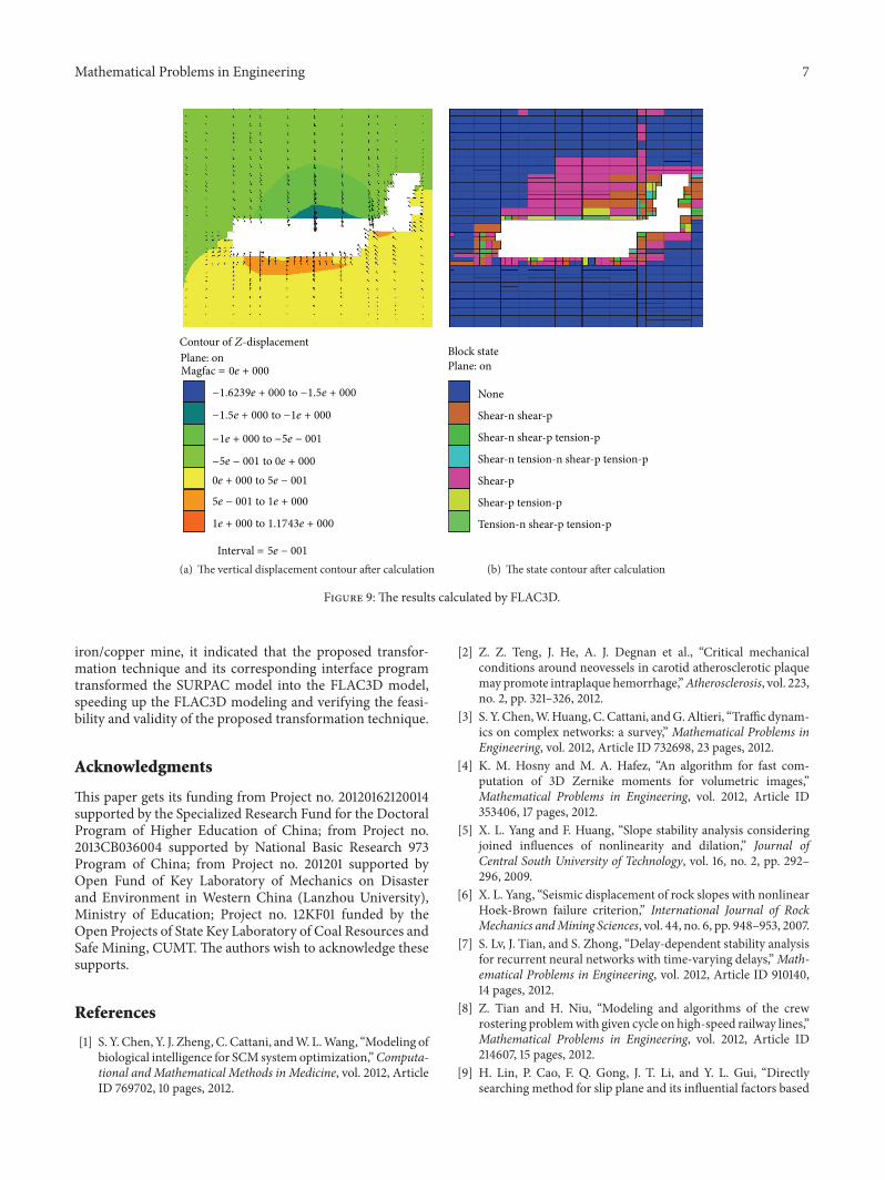
After calculation by FLAC3D, the displacement and statecontours are shown in Figure 9, which is in consistence withthe real situation.
4. Conclusion
(1) Considering the difficulty of using FLAC3D (geotech-nical calculation software) for pretreatment modeling, thecurrent study combined SURPAC (mine design software) andFLAC3D to utilize the advantage of SURPAC in simulatinggeological features and to provide a calculation model thatconforms to the geological reality of FLAC3D.
(2)The differences between the information from the twotypes of unit information, that is, SURPAC and FLAC3D,were analyzed, the data relationship between units was built,the data transformation technique was proposed, and theFORTRAN was adopted to compile relevant transformationprocedures.
(3) When the transformation technique proposed in thecurrent paper was applied to the modeling of a given large
Mathematical Problems in Engineering 7
Plane: onMagfac = 0𝑒 + 000
−1.6239𝑒 + 000 to −1.5𝑒 + 000
−1.5𝑒 + 000 to −1𝑒 + 000
−1𝑒 + 000 to −5𝑒 − 001
−5𝑒 − 001 to 0𝑒 + 0000𝑒 + 000 to 5𝑒 − 001
5𝑒 − 001 to 1𝑒 + 000
1𝑒 + 000 to 1.1743𝑒 + 000
Interval = 5𝑒 − 001
Contour of 𝑍-displacement
(a) The vertical displacement contour after calculation
Block statePlane: on
None
Shear-n shear-p
Shear-n shear-p tension-p
Shear-n tension-n shear-p tension-p
Shear-p
Shear-p tension-p
Tension-n shear-p tension-p
(b) The state contour after calculation
Figure 9: The results calculated by FLAC3D.
iron/copper mine, it indicated that the proposed transfor-mation technique and its corresponding interface programtransformed the SURPAC model into the FLAC3D model,speeding up the FLAC3D modeling and verifying the feasi-bility and validity of the proposed transformation technique.
Acknowledgments
This paper gets its funding from Project no. 20120162120014supported by the Specialized Research Fund for the DoctoralProgram of Higher Education of China; from Project no.2013CB036004 supported by National Basic Research 973Program of China; from Project no. 201201 supported byOpen Fund of Key Laboratory of Mechanics on Disasterand Environment in Western China (Lanzhou University),Ministry of Education; Project no. 12KF01 funded by theOpen Projects of State Key Laboratory of Coal Resources andSafe Mining, CUMT.The authors wish to acknowledge thesesupports.
References
[1] S. Y. Chen, Y. J. Zheng, C. Cattani, andW. L.Wang, “Modeling ofbiological intelligence for SCM systemoptimization,”Computa-tional and Mathematical Methods in Medicine, vol. 2012, ArticleID 769702, 10 pages, 2012.
[2] Z. Z. Teng, J. He, A. J. Degnan et al., “Critical mechanicalconditions around neovessels in carotid atherosclerotic plaquemay promote intraplaque hemorrhage,”Atherosclerosis, vol. 223,no. 2, pp. 321–326, 2012.
[3] S. Y. Chen,W.Huang, C. Cattani, andG.Altieri, “Trafficdynam-ics on complex networks: a survey,” Mathematical Problems inEngineering, vol. 2012, Article ID 732698, 23 pages, 2012.
[4] K. M. Hosny and M. A. Hafez, “An algorithm for fast com-putation of 3D Zernike moments for volumetric images,”Mathematical Problems in Engineering, vol. 2012, Article ID353406, 17 pages, 2012.
[5] X. L. Yang and F. Huang, “Slope stability analysis consideringjoined influences of nonlinearity and dilation,” Journal ofCentral South University of Technology, vol. 16, no. 2, pp. 292–296, 2009.
[6] X. L. Yang, “Seismic displacement of rock slopes with nonlinearHoek-Brown failure criterion,” International Journal of RockMechanics andMining Sciences, vol. 44, no. 6, pp. 948–953, 2007.
[7] S. Lv, J. Tian, and S. Zhong, “Delay-dependent stability analysisfor recurrent neural networks with time-varying delays,”Math-ematical Problems in Engineering, vol. 2012, Article ID 910140,14 pages, 2012.
[8] Z. Tian and H. Niu, “Modeling and algorithms of the crewrostering problemwith given cycle on high-speed railway lines,”Mathematical Problems in Engineering, vol. 2012, Article ID214607, 15 pages, 2012.
[9] H. Lin, P. Cao, F. Q. Gong, J. T. Li, and Y. L. Gui, “Directlysearching method for slip plane and its influential factors based
8 Mathematical Problems in Engineering
on critical state of slope,” Journal of Central South University ofTechnology, vol. 16, no. 1, pp. 131–135, 2009.
[10] S. Kwon, W. J. Cho, and P. S. Han, “Concept developmentof an underground research tunnel for validating the Koreanreference HLW disposal system,” Tunnelling and UndergroundSpace Technology, vol. 21, no. 2, pp. 203–217, 2006.
[11] J. Rutqvist, Y. Ijiri, and H. Yamamoto, “Implementation of theBarcelona Basic Model into TOUGH-FLAC for simulations ofthe geomechanical behavior of unsaturated soils,” Computersand Geosciences, vol. 37, no. 6, pp. 751–762, 2011.
[12] H. Lin and S. W. Sun, “Influence of pile position and lengthon stress deformation behaviors of layered rock mass slope,”Disaster Advances, vol. 5, no. 4, pp. 422–426, 2012.
[13] A. Bhattacharjee and A. M. Krishna, “Development of numer-ical model of wrap-faced walls subjected to seismic excitation,”Geosynthetics International, vol. 19, no. 5, pp. 354–369, 2012.
[14] R. Hasanpour, H. Chakeri, Y. Ozcelik, and H. Denek, “Eval-uation of surface settlements in the Istanbul metro in termsof analytical, numerical and direct measurements,” Bulletin ofEngineeringGeology and the Environment, vol. 71, no. 3, pp. 499–510, 2012.
[15] S. T. McColl, T. R. H. Davies, and M. J. McSaveney, “The effectof glaciation on the intensity of seismic ground motion,” EarthSurface Processes and Landforms, vol. 37, no. 12, pp. 1290–1301,2012.
[16] R. Rai, M. Khandelwal, and A. Jaiswal, “Application of geogridsin waste dump stability: a numerical modeling approach,”Environmental Earth Sciences, vol. 66, no. 5, pp. 1459–1465, 2012.
[17] N. X. Xu, H. Tian, P. Kulatilake, and Q. W. Duan, “Building athree dimensional sealed geological model to use in numericalstress analysis software: a case study for a dam site,” Computersand Geotechnics, vol. 38, no. 8, pp. 1022–1030, 2011.
[18] N. X. Xu, X. Wu, X. G. Wang, Z. X. Jia, and Q. W. Duan,“Approach to automatic hexahedron mesh generation for rock-mass with complex structure based on 3D geologicalmodeling,”Chinese Journal of Geotechnical Engineering, vol. 28, no. 8, pp.957–961, 2006.
[19] M. Grenon and A.-J. Laflamme, “Slope orientation assessmentfor open-pit mines, using GIS-based algorithms,” Computersand Geosciences, vol. 37, no. 9, pp. 1413–1424, 2011.
[20] N. M. Sirakov and F. H. Muge, “A system for reconstructingand visualising three-dimensional objects,” Computers andGeosciences, vol. 27, no. 1, pp. 59–69, 2001.
[21] M. Grenon and J. Hadjigeorgiou, “Integrated structural stabilityanalysis for preliminary open pit design,” International Journalof Rock Mechanics and Mining Sciences, vol. 47, no. 3, pp. 450–460, 2010.
[22] N. M. Sirakov, I. Granado, and F. H. Muge, “Interpolationapproach for 3D smooth reconstruction of subsurface objects,”Computers and Geosciences, vol. 28, no. 8, pp. 877–885, 2002.
[23] Q. Wu and H. Xu, “An approach to computer modelingand visualization of geological faults in 3D,” Computers andGeosciences, vol. 29, no. 4, pp. 503–509, 2003.
[24] D. H. Zhong, M. C. Li, L. G. Song, and G. Wang, “EnhancedNURBS modeling and visualization for large 3D geoengi-neering applications: an example from the Jinping first-levelhydropower engineering project, China,” Computers and Geo-sciences, vol. 32, no. 9, pp. 1270–1282, 2006.
[25] B. A. Flores and I. E. Cabral, “Analysis of sensitivity of the piteconomic optimization,” Revista Escola de Minas, vol. 61, no. 4,pp. 449–454, 2008.
[26] Z. Q. Luo, L. Xiao-Ming, S. Jia-Hong, W. Ya-Bin, and L. Wang-Ping, “Deposit 3Dmodeling and application,” Journal of CentralSouth University of Technology, vol. 14, no. 2, pp. 225–229, 2007.
[27] Z. Q. Luo, X. M. Liu, B. Zhang, H. Lu, and C. Li, “Cavity 3Dmodeling and correlative techniques based on cavity monitor-ing,” Journal of Central South University of Technology, vol. 15,no. 5, pp. 639–644, 2008.
[28] Itasca Consulting Group, “Fast lagrangian analysis of continuain 3 dimensions,” User Manual Version 3.1, 2004.

Submit your manuscripts athttp://www.hindawi.com
Hindawi Publishing Corporationhttp://www.hindawi.com Volume 2014
MathematicsJournal of
Hindawi Publishing Corporationhttp://www.hindawi.com Volume 2014
Mathematical Problems in Engineering
Hindawi Publishing Corporationhttp://www.hindawi.com
Differential EquationsInternational Journal of
Volume 2014
Applied MathematicsJournal of
Hindawi Publishing Corporationhttp://www.hindawi.com Volume 2014
Probability and StatisticsHindawi Publishing Corporationhttp://www.hindawi.com Volume 2014
Journal of
Hindawi Publishing Corporationhttp://www.hindawi.com Volume 2014
Mathematical PhysicsAdvances in
Complex AnalysisJournal of
Hindawi Publishing Corporationhttp://www.hindawi.com Volume 2014
OptimizationJournal of
Hindawi Publishing Corporationhttp://www.hindawi.com Volume 2014
CombinatoricsHindawi Publishing Corporationhttp://www.hindawi.com Volume 2014
International Journal of
Hindawi Publishing Corporationhttp://www.hindawi.com Volume 2014
Operations ResearchAdvances in
Journal of
Hindawi Publishing Corporationhttp://www.hindawi.com Volume 2014
Function Spaces
Abstract and Applied AnalysisHindawi Publishing Corporationhttp://www.hindawi.com Volume 2014
International Journal of Mathematics and Mathematical Sciences
Hindawi Publishing Corporationhttp://www.hindawi.com Volume 2014
The Scientific World JournalHindawi Publishing Corporation http://www.hindawi.com Volume 2014
Hindawi Publishing Corporationhttp://www.hindawi.com Volume 2014
Algebra
Discrete Dynamics in Nature and Society
Hindawi Publishing Corporationhttp://www.hindawi.com Volume 2014
Hindawi Publishing Corporationhttp://www.hindawi.com Volume 2014
Decision SciencesAdvances in
Discrete MathematicsJournal of
Hindawi Publishing Corporationhttp://www.hindawi.com
Volume 2014 Hindawi Publishing Corporationhttp://www.hindawi.com Volume 2014
Stochastic AnalysisInternational Journal of


![Simple complex sentences[1]](https://img.pdfslide.us/doc/110x75/55a216e81a28abe7118b4694/simple-complex-sentences1.jpg)