Embed Size (px)
Citation preview

NASA Technical Memorandum 103811
Research and Technology
1990 Annual Report
of the John F. Kennedy
Space Center

J

FOREWORD
As the NASA Center responsible for assembly, checkout, servicing, launch,
recovery, and operational support of Space Transportation System elements and
payloads, the John F. Kennedy Space Center is placing increasing emphasis on its
research and technology program. In addition to strengthening those areas of
engineering and operations technology that contribute to safer, more effÉcient,and
more economical execution ofour current mission, we are developing the technological
tools needed to execute the Center's mission relative to future programs. The
Engineering Development Directorate encompasses most ofthe laboratories and other
Center resources that are key elements ofthe research and technology program, and
is responsible for implementation of the majority of the projects in this Kennedy
Space Center 1990 Annual Report.
Thomas M. Hammond, Technology Utilization Officer, PT-PMO-A, (407)
867-3017, is responsible for publication of this report and should be contacted for any
desired information regarding the Center-wide research and technology program.
VForrest S. McCa
Director

oi _m
AVAILABILITY INFORMATION
For additional information on any individual report,
contact the person identified following the article. Com-mercial telephone users can dial the listed extension
preceded by area code 407. Telephone users with access tothe Federal Telecommunications System can dial the
extension preceded by 823.
ii

CONTENTS
MATERIALS SCIENCE .............................................
Conductive Organic Polymers as Corrosion Control Coatings ...................
The objective of the research effort is to develop organic corrosion controlcoatings that are easily applied and repaired, resistant to the acid launchenvironment, and stable to intermittent temperature excursions to
400 degrees Celsius.
Environmentally Compliant Coating Systems for the Shuttle LaunchSites ...........................................................
Environmentally compliant, inorganic, zinc coating systems for protection oflaunch site structures and equipment are undergoing evaluation for usein the Kennedy Space Center environment.
Stress Testing of Engineering Materials ..................................
Testing is being conducted on 50 common metallic alloys to determinetheir susceptibility to stress corrosion cracking in the Shuttle launchenvironment.
Accelerated Testing of Inorganic, Zinc-Rich Primers .........................
Electrochemical techniques are being investigated as an acceleratedmethod for testing the corrosion resistance of inorganic, zinc-richprimer systems for use on Kennedy Space Center launch structures andequipment.
Protective Coating Systems for Repaired Carbon Steel Surfaces .................
New metal coating products are undergoing laboratory and field evaluationtests to determine their ability to protect repaired carbon steel from theKennedy Space Center marine and launch environment even if surfacepreparations are less than perfect.
Study of Thermal-Sprayed Metallic Coatings for Potential Applicationon Launch Complex 39 Structures .......................................
This study is evaluating candidate thermal-sprayed metallic coatings forpotential application to structures on Launch Complex 39 at KennedySpace Center.
3
5
6
7
8
9
lio
111

CONTENTS (Cont)
Corrosion of Convoluted Metal Flexible Hoses ..............................
Exposure of a number of aUoys to a salt and acid environment has
resulted in selecting HasteUoy C-22 as the optimum material for
fabricating convoluted metal flexible hoses. A simple electrical
impedance test maybe the key for measuring an aUoy's susceptibilityto acid- and salt-induced corrosion.
Thermal-Sprayed Cathodic Protection for Steel Structures .....................
A study is being conducted to evaluate cathodic TSC systems in thetropical marine environment of Kennedy Space Center.
Protective Top Coating Systems for the Space Transportation System
Launch Environment .................................................
Top coatings, for the protection of zinc-rich primers (applied to launch site
structures and equipment) from the acidic residues produced by solid
rocket boosters, are undergoing a 5-year, harsh-environment exposure
program.
Aqueous Precision Cleaning ............................................
An effort is underway to find an environmentally acceptable replacementfor CFC-113, which is currently used for precision cleaning at Kennedy
Space Center.
Development of New Flooring Materials for Clean Rooms and Launch Site
Facilities ..........................................................
A formulation of chemically resistant polymers, conductive fillers, flame-
retardant additives, and low outgassing plasticizers is a potential replace-
ment for commercial PVC tiles.
Development of a New Chemical-Resistant Fabric for Protective Clothing .........
A program to identify a fabric resistant to toxic propellants used atKennedy Space Center has been initiated that will eventually result
in the next generation of completely encapsulating protective suits.
COmpatibility of Corr0sion:Resistant Alloys With Aerospace Fluids ..............
A study of alloys resistant to the Kennedy Space Center environment has been
initiated to determine their susceptibility to hydrogen embrittlement and
stress-corrosion cracking in typically used aerospace fluids.
11
12
12
13
15
15
16
iv

CONTENTS (Cont)
Fracture Susceptibility Study of Corrosion-Resistant Alloys ....................
A joint program has begun to study the stress corrosion cracking susceptibility,corrosion fatigue, and hydrogen embrittlement of corrosion-resistant alloys.
16
HAZARDOUS EMISSIONS AND CONTAMINATION MONITORING ......... 18
Quick-Response Oxygen Analyzers ..........................t
Fast-response oxygen monitors are being investigated for use in the SpaceStation Processing Facility at Kennedy Space Center.
Integrated Environmental Monitoring System ..............................
An instrumentation system consisting of particle counters, temperature/
relative humidity sensors, oxygen deficiency monitors, and toxic vapordetectors is being developed for use in the planned Space StationProcessing Facility. The system will be composed of both fixed andportable monitors. ,
Evaluation of a Dual Filter Photoacoustic Infrared Hypergolic
Fuel Vapor Detector .................................................
Evaluation of a dual filter photoacoustic infrared detector for potential
use in the Hypergolic Vapor Detection System at Launch Complex 39at Kennedy Space Center.
Evaluation of the Interscan RLD Electrochemical Sensor for Hypergolic
Fuel Vapor Detection .................................................
Evaluation of the Interscan RLD monomethylhydrazine electrochemicalcell for potential use in the Hypergolic Vapor Detection System on
Launch Complex 39 at Kennedy Space Center.
Monomethylhydrazine Active Sampler Using Vanillin Chemistry ................
Test and evaluation of the use of vanillin chemistry in active samples forrapid detection of monomethylhydrazine at a lO-part-per-billion level.
Multispectral Imaging of Hydrogen Flames ................................
Development of an imaging system using multispectral television tech-niques to detect and display hydrogen flames.
2O
2O
22
26
28
29
v

CONTENTS (Cont)
Color Chemistry for Nitrogen Dioxide Detection ............................
Investigation of color chemistry for nitrogen dioxide (NO_) detection. Thechemistry will be applied for the development of N02 dosimeters.
Evaluation of Realtime Portable Nitrogen Dioxide Detectors ...................
A comparative evaluation of four nitrogen dioxide detectors for meetingnew OSHA short-term exposure limits.
Detection of Parts-Per-Billion Concentrations of Monomethylhydrazine
Vapor in Air by the Coulometric Method ..................................
Evaluation of the vapor scrubbing system and the coulometric test procedurefor the low-level vapor verifwation of rnonomethylhydrazine.
Hydrogen Dispersion Nozzle Testing .....................................
A test was run on a nozzle to be used to disperse Space Shuttle hydrogenleaks in the 17-inch line between the Orbiter and external tank.
Evaluation of an Optical Infrared Hypergolic Fuel Vapor Detector ...............
Evaluation of an optical infrared detector for potential use in theHypergolic Vapor Detection System on Launch Complex 39 at
Kennedy Space Center.
Evaluation of Photoionization Detectors for Hypergolic Fuel VaporDetection ..........................................................
Evaluation of five photoionization detectors for monomethylhydrazinedetection.
Preliminary Evaluation of a Fourier Transform Infrared Spectrometer
for Hypergolic Fuel Vapor Detection .....................................
Investigation of the feasibility of using Fourier transform infrared spectro-scopy for hypergolic fuel vapor detection.
Realtime Particle Fallout Monitor .......................................
A realtime monitor for particle deposition on payload surfaces is beingdeveloped and tested.
31
32
34
41
43
48
5O
53
vi

CONTENTS (Cont)
Advanced Hazardous Gas Detection System (AHGDS) ........................
Development ofa hazardous gas detectionsystemthatisreliableand
accuratetoupgrade thepresentlyused detectionsystemsand foruse on
the Advanced Launch System.
BIOSCIENCES ....................................................
Vegetation Studies and Biospherics Research ..............................
Analysis of the effects of fire on wetlands continues.
Habitat Assessment Group ............................................
Functions include the development of methods to interpret and predictthe effects of ongoing and proposed operations at Kennedy Space Centeron wildlife and habitat.
Plant Space Biology Program ...........................................
Research into supplying plants with water and nutrients and theirphysiological response to altered gravity continues.
Orbiter Environmental Simulator .......................................
The Orbiter Environmental Simulator simulates Orbiter flight environment.
Human Physiology Research Projects:Blood Pressure Control .................
Two major research projects were undertaken to determine the effects ofspaceflight and exercise on the blood pressure control system in man.
ControlledEcologicalLife Support System (CELSS) BiomassProduction Chamber .................................................
Crop tests inside the CELSS Biomass Production Chamber (BPC) continued
during the past year, including two tests each with soybean (Glycine max)and lettuce (Lactuca sativa).
Biomass Processing Research ...........................................
Development continues on the conversion processes for transforming bio-mass production chamber crop harvest residues into edible products.
54
56
58
59
61
64
65
66
67
vii

CONTENTS (Cont)
69Air Quality Monitoring ...............................................
Long-term ambient monitoring of pollutants and recording of local
meteorological conditions continue at rAMS.
Raster Vector Integration ............................................. 70
The Remote Sensing and Geographical Information Systems Laboratory
has the ability to integrate raster data and vector data.
Aquaculture Research ................................................ 70
A closed aquaculture system including a fish tank and fluidized-bed bio-
filter has been constructed.
Biomass Production Research .......................................... 71
The influence of CO_ concentration and light spectrum on soybean and
potato plants is being studied.
Tubular Membrane Plant Growth Unit ................................... 72
Work continues on optimizing the nutrient delivery system design being
developed for growing plants in microgravity.
Development of a Method for Imaging Muscle Cross Section Using
Magnetic Resonance , .................................... ............ 72
A program was written to view images and calculate muscle cross-sectionalareas.
The Important Role of Eccentric Muscle Actions in Exercise
Countermeasures .................................................... 72
A research study has been conducted at Kennedy Space Center to deter-mine if eccentric actions are essential for inducing optimal adaptive
responses to resistance training.
AUTONOMOUS SYSTEMS ........................................... 74
Orbiter TPS Automation Study ......................................... 76
A comprehensive Orbiter Thermal Protection System (TPS) process auto-
mation study was performed and a unified robotic system (mobile
platform, lifting device, SCARA robot arm, and sensor package) concept
was developed for the viable TPS processes.
oQo
Vlll

CONTENTS (Cont)
Payload Processing System Study .......................................
An exhaustive study of payload processes was conducted to identifyautomation and robotic enhancements in processing payloads at
various facilities at Kennedy Space Center.
Automation of Payload Canister Cleaning .................................
A study to produce a 2-DOF robotic device on an existing 4-DOF platformthat will automatically clean the inside of the payload canister to cleanroom standards has been implemented.
Orbiter Radiator Damage Inspection .....................................
A program is being initiated to develop a highly reliable (total componentredundancy) robotic system integrated with an inspection sensor that canautomatically locate and inspect damages to Orbiter radiator panels.
High-Speed Flexible Robot Controller ....................................
A replacement is being developed for robot controllers that will allow high-speed communication to a supervisory control computer and allow flexibilityof reprogramming the controller since its control instructions are not fixedin firmware or hardware. This will enable development of realtime force-torque control.
Knowledge-Based Autonomous Test Engineer (KATE) - A Model-Based
Control and Diagnostic Shell ...........................................
A model-based approach to autonomous control and diagnosis is beingdeveloped for ground support equipment.
Remote Umbilical Plate Docking]Insertion .................................
A robotic mechanism and target tracking system is being developed toremotely mate a pair of large-capacity umbilical connections under space-craft dynamics.
Torque Sensing End-Effector (TSEE) .....................................
An intelligent robotic end-effector to open or close valves during hazard-ous maintenance and emergency sating operations is being developed.
Intelligent Launch Decision Support System (ILDSS) ........................
Software tools are being developed to support decisionmaking by the launch
team during Shuttle launch countdown in the areas of time management andoperational access to the Launch Commit Criteria.
77
80
81
85
88
96
99
100
ix

r
CONTENTS (Cont)
COMMUNICATIONS AND CONTROL ................................. 104
Fiber Optics, Communications, and Networks Laboratory ..................... 106
This laboratory provides engineering support for the optimization of copperand optical f_ber communication links at Kennedy Space Center.
Direct Fiber to Operational Television Camera System ....................... 108
The Fiber Optics, Communications, and Networks Laboratory is partici-pating in the development of a television camera system that will bethe prototype for the next generation of an operational television (OTIOsystem camera for use on the launch pad.
METEOROLOGY ................................................... 111
Field Testing of the Sandia Transportable Triggered-Lightning
Instrumentation Facility (SATTLIF) .....................................
For investigating the effects of lightning environments on the safety andreliability of nuclear weapons storage structures, the SATTLIF wasdeveloped and field tested.
Meteorological Monitoring System (MMS), Phase I ..........................
During Phase I, state-of-the-art computer techniques were researched todesign a system for the automated realtime monitoring of critical weatherelements at Kennedy Space Center.
112
113
TECHNOLOGY UTILIZATION ....................................... 115
Magnetic Resonance Imaging Technology .................................. 116
NASA satellite imaging computer technology is being applied toMagnetic Resonance Imaging (MRI) to improve detection and treat-ment of cancerous tumors.
Development of a Digital Hearing Aid .................................... 117
Customizing the physical and acoustical parameters of hearing aids to theneeds of users by use of digital circuitry and adaptive fitting procedures
results in an improved design.
I

CONTENTS (Cont)
Mobile Heat Pipe Air Conditioner .......................................
An experimental air conditioner was developed using heat pipe technologyfor the purposes of heat dissipation, dehumidification, and energy saving.
Heat Pipe in Radon Mitigation (Dinh Radon Fighter) ........................
A fresh-air heat pump was developed that mitigates radon and flushesindoor contaminants in an efficient and low-cost manner.
MECHANICS, STRUCTURES, AND CRYOGENICS .......................
Response of Structures to Random Acoustic Excitation .......................
For the design of launch pad structures, a stochastic modeling approach isbeing developed to predict structural response to launch acoustics.
119
120
122
124
xi


Materials Science
Materials science investigations are con-ducted in two well-equipped and well-staffedlaboratories at the John F. Kennedy SpaceCenter (KSC).
Microchemical Analysis Laboratory
The Microchemical Analysis Laboratory
employs high technology instruments, suchas the electron microprobe, scanning elec-
tron microscope, infrared spectrophotometer,
and mass spectrometer/gas chromatograph,as well as classical analytical methods, to
identify a variety of materials. One basic
function of the laboratory is to chemicallyidentify any fluid or solid material down to
the parts-per-billion range. A second basic
function is to provide the investigative effortnecessary to understand and solve chemical
problems associated with the selection and
application of materials in aerospace sys-tems. Typical subjects for analysis are the
Shuttle thermal protection system, aero-space materials (such as alloys and soft
goods), and any contamination found on orin flight hardware or facilities.
Failure Analysis and Materials Evaluation
Laboratory
The failure analysis portion of this lab-
oratory provides the investigative capability
to determine, on a rapid turnaround basis,
the causes of failures related to ground
support equipment and flight hardware.
The failure analysis process is conducted in
the electrical/electronics, mechanical/fluid,
metallurgical, and metrological laboratories,
with supporting expert services within each
of these areas. After the completion of an
investigation, the engineer or physicist
makes recommendations for preventing
similar occurrences and, if necessary, devis-
es a research program with the goal of
preventing future failures.
The materials evaluation portion of this
laboratory includes materials and environ-
mental testing" facilities, a liquid oxygen
impact testing facility, and an environmen-
tal exposure test site along the Atlantic
Ocean. This section of the laboratory pro-
vides the investigative effort necessary to
understand and solve technical problems
associated with the selection and application
of materials (such as plastics, elastomers,
metals, and lubricants) used in flight hard-
ware, ground support equipment, and facili-
ty systems.
1

Research and Technology 1990
ORIGINAL PAGE
BLACK AND WHITE PHOTOGRAPH
Microchemical Analysis Laboratory
Materials Evaluation Laboratory
\
• .k _
- _ _-
m_.,)
!k
Failure Analysis Laboratory
2

Materials Science
Conductive Organic Polymers asCorrosion Control Coatings
Electrically conductive polymers are beingsynthesized and formulated as protectivecoatings for ground support equipment andstructures at Kennedy Space Center (KSC).
The disadvantage of the current zinc-rich
coatings used on launch structures is that
the high concentrations of hydrochloric acid
released during a Space Shuttle launch
attack the zinc portion of the coating. The
search for a coating with resistance to hy-drochloric acid and to corrosion has focused
on conductive polymers--materials with the
electronic and magnetic properties of metal
but with properties such as flexibility and
chemical resistance of polymers.
The objective of the conjunctive research
effort involving KSC and the Los Alamos
National Laboratory (LANL) is to developcoatings from conductive organic polymers
that will provide galvanic protection to steelsurfaces. These organic coatings should be
formulated to provide easy application,
repair, and long-term resistance to the KSClaunch environment. The launch environ-
ment consists of a marine, severe solar, and
intermittently high acid-elevated tempera-
ture environment. The high acid-elevated
temperature conditions are generated during
vehicle launches using solid rocket motors.
Historically, the field of electrically con-
ductive polymers has produced materials
that have virtually no processibility. How-
ever, in the last few years, it has been dis-covered that aniline, the 3-substituted thio-
phenes, and pyrroles can_be synthesized and
polymerized to high-molecular-weight mate-
rials. In the research effort involving KSC-
and LANL, the nature of the substituents
has been carefully controlled, resulting in
polymers readily soluble in common organicsolvents and ones that can be melt-processed
below decomposition temperatures. Thus,
feasibility has been demonstrated for mak-
ing processible polymers that are electricallyconductive.
In the past year, several conductive poly-mers have been synthesized, and solutions of
sufficient viscosity for casting films have
been prepared. Solvents, casting techniques,
and drying conditions have been developed
for coating steel coupons with pinhole-free
films of pi-conjugated polymers. The most
promising materials at present are
poly(alkylthiophenes) and polyaniline.
Blending agents have been used in combina-tion with the conductive polymers to in-
crease film strength and adhesion to steelsubstrates.
The table "Properties of Processible Con-
ductive Polymers" summarizes the proper-
ties for the most promising of the conductive
polymers and conductive polymer blends.
For suitability of any material to provide the
desired corrosion protection, the material
must demonstrate good/excellent properties
in several categories: (1) ease of preparation
and processing, (2) dopability (i.e., increasing
conductivity by ionic additives), (3) electrical
conductivity, (4) environmental stability, (5)
mechanical integrity of film, and (6) adhe-sion to steel.
Adhesion to steel seems to be a limitingfactor for the materials investigated. Al-
though many of the polymer films adhere
well to steel in water, the presence of acidslilts the films from the substrate. One
method used to prevent the peeling problem
was to treat the steel surface prior to coat-
ing. Coupling agents were used to covalent-ly bond the polymer coating to the steel
surface. Such treatment was especially
3

Research and Technology 1990
Properties of Processible Conductive Polymers
P3HT P3TEA PAn P3HT/Hyp
Dopability, 12 a d a a
a b a aDopability, acid
Ease of preparation
Ease of processing
Atmospheric stability
Processing of filmswith no pinholes
b
b
b
b
b
a
a
a
a
a
a
Film elasticity b d c
Adhesion: H20 b a b
b b b
b
Maximum conductivity
Permeability: H ÷ Yes Yes
CI" Yes Yes
? ?
a
PAn/I-Iyp PAn/Epo
a b
a
a
b
b b
a a
a a
d d
NaCl/O 2 b
HC! d d d d c
c b c e e
Fe n+
b
b d a
d
(No irondetectedafterex-
posureto steelcoupon incorrosiveenvironment)
d,n
b
Yes
?
?
Notes: a = Excellentb = Good
c = Averaged =Poor
P3HT = Poly (3-hexylthiophene)P3TEA = Poly (3-thienylethylacetate)PAn = PolyanilineHyp = HypalonEpo = Epon 828 epoxy
effective in marine environments. Samples
were immersed in sodium chloride aqueous
solutions with vigorous oxygen bubbling.
Under these conditions, the polymer films
adhered strongly to the steel coupons and
the polymer-coated steel remained uncor-
roded even upon prolonged exposure. How-
ever, this surface treatment utilizing cou-
pling agents has not been found effective in
acidic environments. The polymer films
remained adhered to steel coupons in a 1-
molar hydrochloric acid solution for 24 hours
with no corrosion under the coating, but the
coatings wrinkled and peeled off when
rinsed and dried.
A second strategy for improving adhesion
of polymer coatings to steel is to blend epoxy
materials with the polymer. Composites of
various epoxy systems with conductive
polymers were formulated, varying the mix
ratios. The choice of curing agent is a very
important aspect in obtaining conductive
polymer/epoxy composites with a desirable
4

Materials Science
balance of physical properties and electrical
conductivity. Therefore, a range of compos-
ites was prepared with different curing
agents. The conductivities achieved thus far
are in the semiconducting range.
Current work is producing improved
composite coatings with higher conductivi-
ties. Such efforts will continue, and proper-
ties of the coatings will be evaluated. Inves-
tigations will include corrosion testing in
both salt water and hydrochloric acid solu-tions. Electrochemical evaluatiorl of the
conductive polymer coating/steel interface
will also be carried out, using alternating
current impedance techniques. Steps have
been undertaken to locate a coatings insti-
tute to produce the most promising coatings
in large batches.
Contact:
K. G. Thompson, 867-4344, DM-MSL-22
Participating Organization:
Los Alamos National Laboratory (B. Benicewicz)
NASA Headquarters Sponsor:
Office of Space Flight
Environmentally Compliant
Coating Systems for the ShuttleLaunch Sites
In 1986, a test program was started to
evaluate protective coating systems on
carbon steel surfaces exposed to simulated
solid rocket booster (SRB) effluent. Test
panels were coated with materials then
available, exposed to the environment at a
beach-side corrosion test site, periodically
sprayed with a simulated SRB acid effluent,
and evaluated after 18 and 36 months. The
coating systems were based on solvent-
thinned, inorganic, zinc-rich primers and
various solvent-thinned topcoat systems.
The findings of this study were that, in
general, the thick-film topcoat products
provided better chemical and corrosion
resistance than the thin-film counterparts
when exposed to the simulated SRB acid
effluent. However, in recent years, environ-
mental regulations have sought to restrict
the use of paints and coatings with a high
concentration of solvent, which could include
many of the coating systems tested in this
study.
The use of the solvent-based, inorganic,
zinc-rich primers tested and approved in the
1986 study could be prohibited at the Ken-
nedy Space Center (KSC) in the near future
due to their volatile organic content (VOC)levels. These materials all have VOC levels
above 450 grams per liter (3.75 pounds per
gallon), whereas the maximum levels al-
lowed in some areas (such as California,
some counties of Florida, and many other
urban areas of the United States) are 420
grams per liter (3.5 pounds per gallon).
Furthermore, legislation has dictated that
this level be reduced to 350 grams per liter
(2.8 pounds per gallon) by 1993. Therefore,
the possibility that the inorganic, zinc-rich
primers and topcoat systems_ presently
approved at KSC will be prohibited and
unavailable for use is very real.
In response to this circumstance, the
current study will be conducted to search for
inorganic, zinc-rich coating systems that
provide superior protection to KSC launch
structures and ground support equipment
and fully comply with environmental regula-
tions. Currently, the protective coating
manufacturing industry is producing envi-
ronmentally compliant, inorganic, zinc
coatings such as high-volume solids and
5

Research and Technology 1990
ORIGINAL PAGE
BLACK AND WHITE PHOTOGRAPH
KSC Corrosion Test Site
water-based systems. New systems are also
being developed to conform to the anticipat-
ed strengthening of environmental air quali-
ty standards.
rated in accordance with ASTM D610 at 18,
36, and 60 months. During this 5-year
period, there will be approximately 130
applications of the acid slurry.
After application of these environmentally
compliant coating systems, the test panels
will be exposed to atmospheric contaminantsat the KSC beach corrosion site with concur-
rent applications of an acid slurry made of
hydrochloric acid (HC1) and alumina (A1203).
To simulate the worst-case scenario experi-
enced at the launch sites, the slurry will be
applied to the test panels with no subse-
quent washdown.
The exposure test will be conducted for 5
years to determine the suitability of the
coating systems. The test panels will be
inspected for performance at 1, 3, 6, 12, 18,36, and 60 months and will be formally
Contact:
L. G. MacDowell, 867.2906, DM-MSL-2
NASA Headquarter Sponsor:
Office of Space Flight
Stress Testing of Engineering
Materials
Stress corrosion cracking (SCC) of metal-lic alloy materials can have a devastating
impact on the safety and reliability of all
types of structures, mechanisms, and high-
pressure gaseous systems. Many times, this
type of failure is unexpected and occurs at
6

Materials Science
the worst possible moment in a schedule or
critical operation of a system. Obviously,
when dealing in high technology areas such
as Shuttle launch and space travel, exoticmetallic materials are used because of their
high strength and lower weight. Typically,
these types of materials are the most suscep-tible to the SCC phenomenon.
In response to this potential problem,
work is underway to determine the SCCbehavior of 50 of the most commonly used
alloys at the Kennedy Space Center(KSC). These materials range from manystainless steels to the more exotic nickel-
based and aluminum alloys. As a result of
this work, materials with lower susceptibili-
ty to stress corrosion will be identified foruse on facilities and systems at KSC.
The work is currently being conducted
under contract to Florida Atlantic University
by the Department of Ocean Engineering.
The materials are being tested using the
slow strain rate technique (SSRT) or con-
stant extension rate technique (CERT) in a
corrosive solution that simulates the Space
Transportation System (STS) launch envi-
ronment. The SSRT test has been accepted
as a reliable method to judge a material's
SCC resistance in a short time. The alloys
are stressed to failure at a slow strain rate
(10 -6 inch per inch per second) in air and
then compared to identical specimens thathave been tested in the corrosive solution.
Differences in fracture surfaces, stress
levels, and times to failure of the specimens
between the two environments are interpret-
ed as variations in susceptibility to SCC.
The study is approximately 80 percent
complete, and the findings will be available
in the near future. The failed specimens are
being analyzed using scanning electron
microscopy (SEM) and the results will be
sent to KSC for publication. These results
will help to prepare a list of engineering
materials that have specific resistance toSCC in the STS launch environment.
Contact:L. G. MacDowell, 867-2906, DM-MSL-2
NASA Headquarters Sponsor:
Office of Space Flight
Accelerated Testing of Inorganic,Zinc-Rich Primers
Inorganic, zinc-rich coatihgs are used for
corrosion protection of car_n steel struc-tures at the Kennedy Space Center (KSC).To be considered for use at I_C, a primer
must successfully withstand e_osure at thebeach corrosion test site. Primers are peri-
odically rated for rusting on a _cale of 1 to10 in accordance with ASTM D610, with a
rating of 10 being the best. For preliminary
approval, primers must receive a rating of 9
or better after 18 months of exposure. For
final approval, primers must continue to
maintain a rating of 9 or better after 60
months. Unfortunately, this process re-
quires a considerable amount of time to
place new products on the approved list.
Alternating current impedance measure-
ment techniques, also known as electrochem-
ical impedance spectroscopy (EIS), are being
studied as a possible method for determining
the corrosion resistance of inorganic, zinc-
rich primers for use at KSC. The goal of
this test program is to develop an accelerat-
ed method for screening zinc-rich primers
before exposing them to long-term testing atthe beach corrosion test site. A reliable
accelerated laboratory test method such as
EIS could save time for preliminary approval
7

Research and Technology 1990
of primers (see the figure "Electrochemical
Corrosion Testing System").
For this method, primers are sprayed on
test coupons for use in the laboratory experi-
ments. These coupons are immersed in
seawater, which is obtained from the Atlan-
tic Ocean close to the beach corrosion site.
The seawater is aerated during the test to
provide the oxygen necessary for corrosion
reactions. Test results should yield informa-
tion on polarization resistance (Rp), which isa measure of a material's resistance to
corrosion in a particular electrolyte. It is
hoped that a correlation can be found be-
tween these laboratory results and the long-term field results.
This test program was started in
November 1989. Results at this point are
encouraging but preliminary. Tests are
being conducted on primers that have al-
ready been exposed at the beach site for 52
months. Laboratory test results will be
Electrochemical Corrosion Testing System
ORIGINAL PAGE
8
compared with these field results. The new-
generation, zinc-rich primers now startingevaluation will also be tested to predict their
field performance.
Contacts:L. G. MacDowell and C. Ontiveros, 867-2906,DM-MSL-24
NASA Headquarters Sponsor:Office of Space Flight
Protective Coating Systems for
Repaired Carbon Steel Surfaces
In the past, maintenance repair of corrod-
ed carbon steel surfaces required the use ofabrasive blasting to adequately clean and
prePare the metal surface for application ofprotective coatings. Recent advances in
coating technology promise acceptable pro-tective coating performance when surface
preparations are less than perfect. The
present study focuses on new products and
techniques that may reduce the level ofsurface cleanliness required for corrosion
protection in many areas at Kennedy SpaceCenter (KSC).
The coatings being tested in this study
include epoxy mastics, moisture-cured ure-thanes, chemical conversion coatings, and
any other type of repair coating identified
during the course of the program. The study
compares the performance of previously
rusted panels that have been mechanically
prepared using four methods and two initialconditions. The four mechanical methods
used are power wire brush, pneumatic
needle gun, sanding disk, and course wheel
grinder. The two initial conditions used are
to prepare the panels with water washing or
without water washing prior to mechanical
cleaning.
BLACK AND WHITE PHOTOGRAPH

Materials Science
The initial screening of the
many products was accom-
plished by exposing the pre-
pared panels to 2,000 hours in
the salt fog chamber. The
results of this screening pro-
cedure indicate varying per-
formances of the coatings of
the same generic type. This
result has considerably re-
duced the final list of productsto be tested. Further results
show that the "rust converter"
type coatings provide little
protection in an aggressive
atmosphere and should not beconsidered for use at KSC.
The materials identified by
the screening procedure have
been used to prepare panels
for exposure at the KSC beach
corrosion test site (see the
figure "Proximity of the Beach
Corrosion Test Site to the Launch Pads").
The panels were prerusted at the beach site
for 6 months and then brought to the labora-
tory for surface preparation and application
of the coating systems. The completed
panels were installed at the beach corrosion
site in July 1990.
Panels exposed at the beach corrosion site
will undergo solid rocke_t booster (SRB)
effluent testing to simulate the conditions at
the launch site. The SRB effluent tests will
be accomplished by spraying simulated
effluent onto two-thirds of the panels every
2 or 3 weeks. Panels at the beach will be
inspected after 1, 3, 6, 12, 18, 36, and 60
months and rated for rusting on a scale from
1 to 10 in accordance with ASTM D610. An
expanded test plan is available under docu-
ment number MTB-144-88.
Proximity of the Beach Corrosion Test Siteto the Launch Pads
Contact:
L. G. MacDowell, 867-2906, DM-MSL-24
NASA Headquarters Sponsor:
Office of Space Flight
Study of Thermal-SprayedMetamc Coatings for PotentialApplication on LaunchComplex 39 Structures
The objective of this study is to evaluate
candidate thermal-sprayed metallic coatings
for potential application on the Zone 1 (high-
temperature rocket motor blast) structures
at Launch Complex 39 at the Kennedy Space
Center. Tests are being performed to deter-
mine' if the candidate coatings will protect
the structure from the abrasive blast, heat,
and acid-rich environment associated with
ORIGINAL PAGE
BLACK AND WHITE PHOTOGRAPH
9

Research and Technology 1990
OR!G!NAL P::.G_:
BLACK AND WHITE pHO'iOG.RA,H'_
Mount Plate With TSC Composite Test
Panels on the Titan Transporter Prior toLaunch
the solid rocket booster (SRB) exhaust dur-
ing Shuttle launches.
Launch Complexes 17 and 40 have beenutilized to test the coatings. Both the Delta
(Launch Complex 17) and the Titan III
(Launch Complex 40) are p_wered by solid
rocket motors (SRM's) and l_rovide a launchenvironment similar to SRB exhaust.
A group of thermal-sprayed coating (TSC)
test panels were set out at the beach corro-
sion test site on April 15, 1987. Periodically,
the panels were rinsed with a slurry of
alumina (A1203) powder and hydrochloricacid (HC1) to simulate the effects of the SRBexhaust residue.
Most of the TSC alloys applied by either
plasma or hypersonic flame spray processes
are more noble than the low-alloy steels. In
the case of these exotic, noble alloys, thecarbon steel structure becomes the sacrificed
anode that corrodes. This undesirable phe-
nomena was illustrated aider 2-1/2 years of
beach exposure testing.
The testing in the launch environment
has illustrated the problems of porosity andexfoliation due to thermal shock. The use of
the exotic TSC's to protect launch structures
appears to be impractical.
Only the relatively low-cost, aluminum
TSC, which provides some cathodic protec-
tion for steel, appears to be a practical
candidate for further investigation.
The aluminum TSC panel with several of
the other materials will be subjected to the
alumina/hydrochloric acid slurry rinse at thebeach corrosion test site.
Mount Plate With TSC Composite Test
Panels on the Titan Transporter AfterLaunch
10

Materials Science
Contact:
P. J. Welch, 867-4614, DM-MSL-2
Participating Organization:
Martin Marietta Manned Space System Launch
Support Services
NASA Headquarters Sponsor:Off-we of Space Flight
Corrosion of Convoluted MetalFlexible Hoses
Various cryogenic supply lines and
hypergolic lines at the Shuttle launch siteuse convoluted flexible hoses and bellows
constructed of type 304L stainless steel. The
extremely corrosive Space Transportation
System (STS) launch environment, composed
of sodium chloride (NaC1) and hydrochloric
acid (HC1), has caused rapid
pitting and failure of these
flexible hoses; this leads to aloss of vacuum with a result-
ing high boiloff of the cryo-
genics.
C-4, C-22, and C-276, performed well. After
evaluation of all mechanical data and corro-
sion tests, Hastelloy C-22 was determined to
be the most acceptable alloy for use in the
STS launch environment (see the figure
"Metal Bellows Repair Using Hastelloy C-
22"). Samples of all alloys continue to be
exposed at the beach corrosion site to gain
valuable long-term exposure data.
During the summer of 1990, testing
continued on the 19 alloys using alternating
current impedance techniques to assess
corrosion resistance. The alloys were tested
in 3.55 percent NaC1 and 0.1 normal HC1 at
varying immersion times. The acidic electro-
lyte was used to simulate conditions that
exist in the STS launch environment. Pre-
liminary data analysis suggests that this
In 1987, a project was initi-
ated to identify a more corro-
sion-resistant alloy for this
service. After testing 19 cor-
rosion-resistant alloys for
pitting resistance, the study
quickly focused on the nickel-
based alloys such as Has-
telloy and Inconel. These
alloys were chosen on the
basis of their reported resis-tance to acid/chloride environ-
ments.
The first-year results were
published under document
number MTB-325-87A. Sever-
al alloys, such as Inco G-3,
Inconel 625, and Hastelloy
F
Metal Bellows Repair Using HasteUoy C-22
ORYGtNAL PACE
BLACK AND WRITE PHOTOGRAPH
11

Research and Technology 1990
technique may prove to be a valuable tool to
rapidly screen metal alloys for their relative
corrosion resistance. The data was pub-
lished under document number MTB-610-
89A.
Contact:
L. G. MacDowell, 867-2906, DM-MSL-24
NASA Headquarters Sponsor:OffiCe of Space Flight
Thermal-Sprayed CathodicProtection for Steel Structures
Throughout the world, hundreds of steelstructures have been metalized with ther-
mal-sprayed coatings (TSC's) to provide
long-term cathodic corrosion protection.
Several of the structures date back to the
1930's.
Studies conducted by the thermal spray
industry indicate that although the initial
cost ofa TSC system is more expensive than
painting, the extended useful service life of
the TSC makes it potentially less expensive
as a long-term investment.
A study is underway to evaluate the
cathodic TSC systems in the tropical marine
environment of the Kennedy Space Center
(KSC) and the chloride-rich environment at
Launch Complex 39. The TSC's will be
compared to the current protection coating
system. Inorganic zinc paints are presently
used to provide cathodic protection of steel
structures. The test panels in this study
will not be subjected to Zone 1 (high-temper-
ature rocket motor blast) conditions.
The three cathodic-type TSC systems
commonly used in industry are being evalu-
ated. The TSC materials are aluminum (A1),
zinc (Zn), and a zinc/aluminum alloy. All
_he TSC's were applied to the test panels bya combustion-spray system. The test panelswith the three TSC materials and the inor-
ganic zinc paint system will be exposed tothe environment at the KSC beach corrosion
test site, Launch Complex 39, and the KSC
Industrial Area.
Contact:P. J. Welch, 867-4614, DM-MSL-2
NASA Headquarters Sponsor:
Office of Space Flight
Protective Top Coating Systems
for the Space Transportation
System Launch Environment
Zinc-rich coating systems exposed to the
Space Transportation System (STS) launch
environment at the Kennedy Space Center
(KSC) have been suffering premature failure
due to the highly acidic residue produced by
the solid rocket boosters. Early attempts at
topcoating these zinc-rich coatings with a
thin film to increase their chemical resis-
tance have produced only marginal results.
Topcoat systems are being tested to im-
prove coating performance for exposure to
KSC's harsh environment (see the figure
"Coating Evaluation of Test Panels at the
Beach Corrosion Test Site"). The present
study focuses on using thicker film topcoats
over the zinc-rich primers to improve the
chemical resistance to a marine atmosphere
and to highly acidic residues.
In 1986, 119 materials producing 67
coating systems were exposed to atmospheric
contaminants at the KSC beach corrosion
site with concurrent applications of an acid
slurry made of hydrochloric acid (HC1) and
12

ORIGINAL PAGE
BLACK AND WHITE PHOTOGRAPH Materials Science
document number MTB-268-86C. Several
manufacturer's topcoat products are, howev-
er, performing very well. This result has
prompted consideration to prepare a fist, for
incorporation into KSC-STD-C-0001, that in-
dudes approved topcoat products for use
when topcoats are required and specified for
launch structures and ground support equip-
ment at KSC.
Contact:
L. G. MacDowell, 867-2906, DM-MSL-24
NASA Headquarters Sponsor:Office of Space Flight
Coating Evaluation of Test Panels at the
Beach Corrosion Test Site
alumina (A1203). To simulate the worst-case
scenario experienced at the launch sites, the
slurry was applied to the test panels with no
subsequent washdown.
Aqueous Precision Cleaning
NASA's policy is to conserve and reduce
the usage of the chlorofluorocarbons (CFC's)
and Halons identified in the Montreal Proto-
cols. In addition, it is planned to phase-out
the use of these materials by 1995.
The current test will be conducted for 5
years to determine the suitability of the
topcoat systems. The panels have been
judged for performance at 6, 12, 18, and 36
months. The last evaluation will occur at 60
months, which will be followed by a final
report. During this 5-year period, there will
have been approximately 130 applications of _-_ _ii
the acid slurry. _:_
The panels are approaching the 52-month
point of exposure. The results of the 18-
month evaluation were published in Febru-
ary 1988 under document number MTB-268-
86B. The 36-month evaluation revealed that
topcoat performance was generally poorer
than the untopcoated condition; the results
were published in September 1989 under
NVR Analysis by Attenuated Total
Reflectance
13

Research and Technology 1990
ORIGINAL PAGE
BLACK AND WHITE PHOTOGRAph
NVR Analysis by Surface Tension
One of these materials, CFC-113, com-
monly referred to as Freon 113, is used for
precision cleaning at the Kennedy SpaceCenter (KSC). CFC-113 is the test solvent
of choice specified in KSC-C-123, Specifica-tion for Surface Cleanliness of Fluid Sys-
tems.
A Kennedy Integrated Team
(KIT) of NASA and KSC con-tractors was formed to find an
environmentally acceptablere-
placement fluid for the precision
cleaning process. The team, the
CFC Replacement Study Team,
is working toward the goal of
using water for precision clean-
ing.
KSC-C-123 identifies CFC-113
as the test solvent used for
cleanliness verification. Clean-
liness verification consists of
particulate analysis and non-
volatile residue (NVR) analysis. Wiltech,
Inc., and the NASA Microchemical Analysis
Branch personnel at the KSC Component
Cleaning and Refurbishment Facility have
been performing most of the research anddevelopment work with some assistance
from the University of Central Florida.
Most of the work to date involves contam-
inated witness plates that are sampled by
the conventional technique, CFC-113, and by
the proposed method using deionized water.
The greatest challenge is posed by perform-
ing the NVR analysis with water. After
performing initial literature searches, mar-
ket research, and screening tests, two tech-niques were selected for test and develop-ment. The first method is fluid surface ten-
sion by dynamic contact angle (DCA) analy-sis, and the second is infrared spectrometric
attenuated total reflectance (ATR) analysis.
The CFC Replacement Study Team is
working with the other NASA Centers in
this effort to solve this environmentally
sensitive problem.
Sampling of Witness Plate Technique Used in the
Aqueous Precision Cleaning Study
14

Materials Science
Contact:
P. J. Welch, 867-4614, DM-MSL-2
Participating Organizations:Wiltech, Inc.University of Central Florida
NASA Headquarters Sponsor:Office of Space Flight
testing of suitable adhesives has begun.Test floors of each material will be installed
for the durability and wear tests at KSC.
Contact:
C. J. Bryan, 867-4344, DM-MSL-2
NASA Headquarters Sponsor:
Office of Space Flight
Development of New FlooringMaterials for Clean Rooms andLaunch Site Facilities
NASA utilizes one of two different static-
dissipating floor coverings in Shuttle assem-
bly areas: flexible polyvinyl chloride (PVC)
tiling or poured epoxy flooring material.
Both have disadvantages associated with
their use. PVC fails NASA's outgassing test
due to the plasticizer component in the
formulation. The plasticizer can volatilize at
room temperature and then recondense on
sensitive optical surfaces. Although there
are static-dissipating PVC tiles commercially
available, none have qualified that have
been subjected to the outgassing test. The
poured epoxy flooring also performs poorly
and is difficult to maintain, repair, and
clean.
A Small Business Innovation Research
(SBIR) project identified chemically resistant
polymers, conductive fillers, flame-retardant
additives, and stabilizers that could be used
to formulate floor tiles which meet NASA's
requirements. Sample formulations, based
on high-density polyethylene and PVC, have
passed outgassing and fluid compatibility
tests at the Kennedy Space Center (KSC).
Dispersion problems with the conductivefiber filler have been solved. Final evalua-
tion of the materials is underway, and
Development of a New Chemical-Resistant Fabric for Protective
Clothing
A program was initiated to identify a
fabric for the next generation of clothing to
protect workers using hazardous chemicalsat the Kennedy Space Center. The hazard-ous chemicals of interest include hydrazine,
monomethylhydrazine, nitrogen tetroxide,
hexane, toluene, sodium hydroxide, citric
acid, 1,1,1-trichloroethane, methyl ethyl
ketone, 2-propanol, and two hydraulic fluids(MIL-H 5605 and MIL-H-83282).
Tuskegee University is the prime con-
tractor for this program. TRUEnviron-
mental, Inc., has been subcontracted tocontact various manufacturers for infor-
mation concerning new barrier materials
that may be suitable for use in protective
clothing. Samples of the more promisingmaterials will be obtained, and the physical
properties and gross chemical resistance
evaluated by TRI. TRI will further evaluatethe candidate materials for ease of fabri-
cation into garments. Tuskegee University
will perform permeability and degradationtests with the hazardous chemicals to deter-
mine the best material for the new chemical-
ly protective suit.
Contact:
C. J. Bryan, 867-4344, DM-MSL-2
15

Research and Technology 1990
16NASA Headquarters Sponsor:Office of Space Flight / Off'we of EqualOpportunity Program
Compatibility of Corrosion-
Resistant Alloys With AerospaceFluids
Nineteen corrosion-resistant alloys were
evaluated several years ago for corrosion
resistance in the Kennedy Space Center
launch environment. Five of these alloys
that exhibited outstanding corrosion resis-tance were identified in this evaluation.
These alloys, Inco (]-3, Inconel 625, and
Hastelloy C-4, C-22, and C-276, were select-
ed for evaluation of their compatibility with
oxygen, hydrogen, hydrazine, monomethyl-
hydrazine, and nitrogen tetroxide. Promoted
combustion tests in oxygen showed these
alloys to be resistant to ignition at pressures
twice as high as those required for consump-
tion of the 300-series stainless steel alloys
evaluated. Rubbing friction tests also
ranked these alloys more resistant to igni-tion than the 300-series stainless steel in
oxygen. Particle impact tests in oxygen are
still pending.
A test chamber is being designed to per-
form slow-strain-rate, stress-corrosion crack-
ing tests on the five alloys in hydrazine,
nitrogen tetroxide, and monomethylhydra-
zine. Hydrogen embrittlement susceptibility
will be evaluated by a slow-strain-rate
method and by static pressurization of a thin
disk after the establishment of steady-state
hydrogen permeation through the disk.
Contact:
C. J. Bryan, 867-4344, DM-MSL-2
NASA Headquarters Sponsor:Office of Space Flight
Fracture Susceptibility Study of
Corrosion-Resistant Alloys
Advancement of technology puts stricter
performance requirements on materials.
Metallic materials are exposed to more
corrosive environments and higher mechani-
cal stresses. A combination of the two
conditions makes metals uniquely suscepti-
ble to fracture failures; therefore, new alloys
are continuously developed to meet the
increasing performance demand.
A joint research program was established
between the Mechanical Engineering De-
partment at the University of Central Flori-
da (UCF) and the Materials Science Labora-
tory of Kennedy Space Center (KSC). The
main goal of this program is to broaden the
knowledge base for fracture resistance of
metallic materials in the highly corrosive,
salt-bearing KSC environment.
The KSC effort focuses upon the stress
corrosion cracking and corrosion fatigue of
recently developed alloys in the natural KSC
environment. Quantification of the KSC
atmosphere and simulation in the laboratory
are planned. A trailer was acquired for a
mobile field laboratory, and a servohydraulic
testing machine will be purchased.
The UCF effort emphasizes the provision
of mechanistic interpretations for crack
propagation processes. A hydrogen embrit-
tlement study in a cathodically charging
environment was initiated. A microscopic
crack propagation study has been in prog-
ress based upon fractography and laser
interferometry.
Together, UCF and KSC have a full line
16

Materials Science
of analytical instrumentation to assist thecorrosion-enhanced fracture studies, includ-
ing Auger electron spectroscopy, X-ray
photoelectron spectroscopy, scanning elec-
tron microscopes, X-ray fluorescence, Fourier
transform infrared spectroscopy, and elec-
tron microprobe.
Contact:R. U. Lee, 867-3400, DM-MSL-22
Participating Organization:University of Central Florida
NASA Headquarters Sponsor:Office of Space Flight
17

Hazardous Emissions and Contamination
Monitoring
The John F. Kennedy Space Center (KSC)stores and pumps huge quantities of cryo-
genics, as well as lesser amounts of exotic
fluids. The extreme toxicity and volatility of
these fluids mandate a comprehensivesafety program. Four development laborato-
ries are responsible for implementing the
specialized instrumentation hardware and
systems that satisfy stringent safety require-ments.
Hazardous Gas Detection Laboratory
The Hazardous Gas Detection Laboratory
has the continuing task of implementingsystems that are capable of measuring (in
complex mixtures) gaseous components both
qualitatively (specifically hydrogen, helium,nitrogen, oxygen, and argon) and quantita-
tively (parts-per-billion range). A typical
hazardous gas detection system comprises a
mass spectrometer, a sample and calibrationgas delivery subsystem, and a data acquisi-
tion and control system. The laboratory
projects now receiving the most attention
are: (1) applying artificial intelligence/expert systems to aid in realtime diagnostics
and troubleshooting, (2) operations moni-
toring and data interpretation, (3) develop-
ing a military specification, and (4) flight-qualified miniature detection systems for ad-
vanced launch systems.
Optical Instrumentation Laboratory
The Optical Instrumentation Laboratory
develops and tests imaging systems for
viewing phenomena that are undetectable tothe unaided eye or by normal viewing tech-
niques (for example, hydrogen fires and
other thermal emitters and hydrogen and
other gas clouds). A recent laboratory
achievement is the design and demonstra-
tion of a multispectral television camera
that is capable of unambiguously imagingand color coding fuel fires in the infrared
and ultraviolet spectral emission ranges.
The laboratory is equipped with an optical
spectrometer for measuring the emission
spectra of an extensive variety of radiatingsources.
Toxic Vapor Detection Laboratory
The Toxic Vapor Detection Laboratory(TVDL) is developing two new series of toxic
vapor detectors because the commerciallyavailable instrumentation does not meet the
current Government standards for measur-
ing trace amounts of hypergolic fuels and
concentrated ammonia vapors in an ambient
background. The TVDL was established to
perform research on detection techniques; to
design, build, and test prototype and/or
modified commercial detectors; and to evalu-ate new commercial instruments. All re-
search and tests are performed utilizing the
TVDL's unique capability to provide a wide
range of toxic vapor concentrations at con-
trolled flow rate, temperature, and relative
humidity conditions. All tests are computer
controlled to provide comprehensive qualita-
tive and quantitative performance evalua-
tions of every instrument tested.
Contamination Monitoring Laboratory
The Contamination Monitoring Laborato-
ry was established to perform contamination
monitoring research and development; to
develop contamination measuring systems;
to evaluate commercially available particle
counters, hydrocarbon and nonvolatile resi-due monitors, and other instrumentation;
and to advance the technology in the areas
18

Hazardous Emissions and Contamination Monitoring
of realtime nonvolatile
residue (NVR), realtime
particle fallout monitor-ing, and contaminationmonitor calibration meth-
odology. The laboratory is
equipped with particle
counter systems, personal-
computer-based dataacquisition and control
systems, a pulse height
analyzer, a research-gradeFourier transform infra-
red (FTIR) spectrophotom-
eter, nondispersive infra-
red analyzers, an aerosol
standards generation
system, an optical micro-
scope, and a normal com-
plement of test and mea-surement instrumenta-
tion.
Toxic Vapor Detection Laboratory
+ + ,,%%+.o-
Hazardous Gas Detection Laboratory
ORIGINAL PAGE
BLACK AND WHITE PHOTOGRAPH
19

Research and Technology 1990II
Quick-Response OxygenAnalyzers
Objective
To evaluate and qualify quick-response
oxygen analyzers for use in the planned
Space Station Processing Facility (SSPF) at
Kennedy Space Center (KSC). Large quanti-
ties of gases such as nitrogen and helium
will be required for payload processing in
the SSPF. These gases will be supplied by
large-volume, high-pressure pipes that will
run through an underground tunnel system.
Since portions of these tunnels and otherareas will have limited air circulation, the
possibility exists that oxygen-deficient pock-
ets could develop; due to leaks in these
pipes, an oxygen deficiency monitoring
system is required.
A_proach
Personnel exposed to an oxygen-deficient
atmosphere may suffer effects ranging from
severe physiological impairment to uncon-
sciousness within 15 seconds. Therefore,
NASA Safety directed that the oxygen moni-
tors used in the SSPF must have a response
time of 10 seconds or less. Since this is a
safety-related system, the design must be
redundant.
Because none of the oxygen analyzers in
use at KSC meet NASA's required response
time, a market survey was needed to find a
replacement. Analyzers based on a variety
of technologies were purchased and evaluat-
ed for accuracy, linearity, time response,
calibration drift, ruggedness, and reliability.
Other factors included in the evaluation
criteria were sensitivity to power surges,
maintenance requirements, and the required
frequency of calibration.
Accomplishments
After performing a market survey, instru-
ments representing a variety of technologies,
including electrochemical, paramagnetic, and
zirconium crystal detectors, were procured.
Qualitative analyses of ruggedness, reliabili-
ty, maintenance requirements, frequency of
calibration, and sensitivity to power glitches
were performed.
Several instruments were identified that
met the 10-second response time require-
ment in preliminary screening. These ana-
lyzers will be subjected to rigorous testing.
Contact:
P. A. Mogan, 867-4438, DL-ESS-24
Participating Organization:McDonnell Douglas Space Station Company(L. H. Allen and D. G. Garretson)
NASA Headquarters Sponsor:
Office of Space Flight
Integrated EnvironmentalMonitoring System
Obiective
To develop an instrumentation system for
monitoring cleanroom environmental condi-
tions in the planned Space Station Process-
ing Facility (SSPF) and related structures
at Kennedy Space Center (KSC). Quantities
to be monitored include temperature, humid-
ity, differential pressure, oxygen deficiency,
and toxic vapors.
2O

Hazardous Emissions and Contamination Monitoring
Background
Processing of flight hardware elements incleanrooms at the SSPF will involve the use
of toxic substances such as hydrazine propel-
lants and ammonia refrigerant. An integrat-
ed system is required to monitor cleanroomconditions (air cleanliness, temperature,
humidity, and differential pressure) and all
toxic or flammable substances that may be
present in each of the cleanrooms.
Approach
Various particle counters, ammonia detec-
tors (for both low and high concentrations),
and hydrazine detectors will be purchased
and evaluated for use in the integrated
environmental monitoring system. Theseinstruments will be evaluated in terms of
performance as well as reliability, rugged-
ness, maintainability and calibration re-
quirements, and features such as alarm,health checks, etc. Data from these instru-
ments will be multiplexed and transmittedto a central data station. A design trade
study will be performed to determine both
the type of computer and networking that
are best suited for the monitoring system.
Since the toxic vapor detection functions
of this monitoring system are safety related,
the design must include redundancy in
instrumentation, power, and alarms.
Accomplishments
A particle counter evaluation program has
been accomplished and several viable instru-ments identified for use in the monitoring
FACILITY AND
PORTABLE
AMMON_
SENSORS
FACILITY
COMTAMINATION
MONITORING
(TEMPERATURE,
HUMIDITY,
PARTICLE COUNT,
AND PRESSURE)
OXYGEN
DEFICIENCY
MONITORS IN
TUNNELS AND
GROUND SUPPORT
EQUIPMENT FLUID
SUPPORT AREAS
LOCAL
(AUDIBLFJVISIBLE)ACCESS CONTROL
OFFICE ALARM PANEL
ALARM I _ICONTROLLER I
DATALOGGER PRINTER
INTERMEDIATE
BAY
FACILITY DATA
ACQUISITION AND
CONTROL SYSTEM
CAUTION AND
WARNING
SYSTEM
DISPLAY
LOCAL ALARM
___(AUDIBLENISIBLE)
EVACUATION
ALARM
CONTROLLER
ACCESS CONTROL
OFFICE ALARM PANEL
Integrated Environmental Monitoring System
21

Research and Technology 1990
system. An appropriate differential pressuretransducer is being qualified for use at KSC
and temperature and humidity sensors havebeen selected.
A design trade study resulted in the
selection of RS-422 networking. Evaluation
of oxygen analyzers and ammonia monitors
is in progress.
Contact:
P. A_ Mogan, 867-4438, DL-ESS-24
Participating Organization:McDonnell Douglas Space Station Company (L. H.Allen, V. V. Bukauskas, J. S. Francis, W. L. Gill,and D. G. Garretson)
NASA Headquarters Sponsor:Office of Space Flight
Evaluation of a Dual FilterPhotoacoustic Infrared
Hypergolic Fuel Vapor Detector
Objective
To perform an in-depth evaluation of acandidate technology for use in the
second-generation Hypergolic Vapor De-
tection System (HVDS II).
Background
In 1989, a preliminary evaluation of
commercially available monomethyl-
hydrazine (MMH) and hydrazine (N2H 4)
detectors was performed at the Kennedy
Space Center Toxic Vapor Detection Labo-
ratory (TVDL). The Bruel&Kjaer Model1302 Toxic Gas Analyzer, although not
included in the 1989 preliminary evaluation,
was tested September 26 to 29, 1989. Model1302 uses the infrared absorption principle.
The broadband source is filtered by six
narrow bandwidth filters. This feature
enables Model 1302 to detect up to six gases
(water vapor plus five more gases) simulta-
neously. Model 1302 has a photoacousticinfrared detector that measures pressure
fluctuations induced by the temperature
changes caused by infrared absorption in asealed sample chamber.
During this abbreviated evaluation, Model
1302 showed very little relative humidity
dependence from 0- to 90-percent relative
humidity at 25 degrees Celsius and was able
to distinguish between MMH, N2H 4, andsome of the expected interferent gases.
Time response, temperature dependence,
and long-term performance were not tested.Based on this abbreviated test, a decision
was made to include a Bruel&Kjaer Model
1306 toxic vapor photoacoustic infrareddetector (PAIR) in the extended test of the
four selected technologies (electrochemical,
photoionization, optical infrared absorption,and photoacoustic infrared absorption) in1990. The difference between Model 1302
and the PAIR is that the PAIR sampled only
two wavebands (water vapor and one gas)
versus the six sampled by Model 1302. The
wavebands used in Model 1302 are 2.5
microns and 11.6 microns.
Approach
The extended test consisted of four parts:
(1) a basic test at the nominal test condition
of 25 degrees Celsius and 45-percent relative
humidity, (2) a long-term (30 day) test, (3)
an environmental test (temperature/relative
humidity extremes), and (4) a special test
[including interference gases, N2H 4
response, and MMH in nitrogen (N 2) re-
sponse]. The linearity, accuracy, precision,
response time, noise, and drift were evaluat-
ed throughout all except the special test.
22

Hazardous Emissions and Contamination Monitoring
The HVDS II technical requirements againstwhich the PAIR was evaluated are shown in
the table "HVDS II Technical Requirem-ents."
Results
The PAIR's performance is summarized in
the table "PAIR Performance Summary,"
and the results of the evaluation are:
o Range and Accuracy/Linearity: The
PAIR, via photoacoustic infrared technol-
ogy, has the capability of providing
several orders of magnitude of range
without saturating the detector. The
o
PAIR maintained linearity (see the
figure "PAIR Linearity Over the 30-Day
Test") and span accuracy (see the figure
"PAIR Span Over the 30-Day Test") over
the entire test.
Precision, Sensitivity, and Noise: The
PAIR has a low signal-to-noise ratio
because the signal change due to absorp-
tion by MMH at the low parts per mil-
lion (ppm) level is very small relative to
the baseline signal. Because of this, the
PAIR failed both the sensitivity and
noise specifications and could only mar-
ginally pass the deviation part of the
precision specification.
HVDS H Technical Requirements
Range
Test
Accuracy/linearity
Precision
Noise
Response time
Humidity
Temperature
16-hour zero drift
30-day drift
Interferent
N2H4
MMH in N 2
Calibration cycle
Maintenance time
Zero and span
Criteria
0 to 30 ppm
Within _+20percentor 0.5ppm ofactual
Span _+10 percent, maximum deviation _+10 percent
0.3 ppm peak-to-peak (zero and span)
10 to 90 percent in < 60 seconds
Deltaspan within_+20percentfrom I0-to90-percentrelativehun_dity
Deltaspan within-+20percentfrom 0 to50 degreesCelsius
Zero drift less than -+1 ppm
Span and zero drift less than _+1ppm
Rejection ratio > 500:1
Measure _+20 percent of actual concentration
Measure _+20 percent of actual concentration
No calibration for 90 days mandatory (180 days de-sired)
No maintenance for 90 days mandatory (180 daysdesired)
Adjustment present
23

Research and Technology 1990
.
.
Time Response: The PAIR failed the
time response specification. Due to the
need to exchange the volume of the test
cell, seal the cell, and then measure the
sample, the PAIR's average sample cycletime was about 65 sec-
onds. The PAIR's sys-
tem response time is
measured in minutes
rather than in seconds. RangeThe failure of the PAIR
to meet the time re-
sponse specifications is a
limitation of the photo- Precision
acoustic infrared tech-
nology and its implemen-tation.
Humidity, Temperature,and Drift: An inherent
problem in infrared
technology is that water
vapor absorbs infrared
in many wavelengths.
However, the PAIR mea-
sured water vapor and
then subtracted the
water vapor contribution
to eliminate relative
humidity dependence.
Readings for three MMH
concentrations with
relative humidity from 0
to 90 percent are shown
in the figure "PAIR Span
as a Function of Relative
Humidity." The PAIR
measurements varied
with temperature but
only to the extent ex-
pected due to the change
of the molar volume with
temperature (a 10-per-
cent-high reading at -5
degrees Celsius and a 7-percent-low
reading at 45 degrees Celsius).
5. Interferents, N2H4, and MMH in Gas-
eous Nitrogen (GN2): The PAIR failed
PAIR Performance Summary
Performance
PAIR capable of orders-of-mag-nitude range
Accuracy/linearity Excellent throughout all tests°
Noise
Test Result*
P
P
P
F
F
P
P
Kept span accurately but ex-ceeded deviation limits periodi-cally over time and at hightemperatures
Failed the noise specification forthe entire test; noise becamemore than 3 ppm at 50 degreesCelsius
Response time Failed all time response specifi-cations
Humidity Met the specifications on allthree relative humidity ramptests
Temperature Passed for all temperatures
16-hour zero drift P Drifted < 0.1 ppm in 16-hourdrift test
30-day drift P Span drift < 0.4 ppm, zero drift< 0.5 ppm
Interferent F Failed all except Freon 114
N2H 4 F Failed; average N2H4/MMHratio equaled 0.25
MMH in N 2 P Passed for entire range
Calibration cycle P No re-span/re-zero needed forduration of test
Maintenance time P No maintenance performed forduration of test
Zero and span P Via remote computer control
*P = Pass; F = Fail
24

Hazardous Emissions and Contamination Monitoring
12
_ 10
0
JUNE 19
" i .....
...................... _.........it....,
..............L-_.,_r?j.......
A
• | • ! . ,2 4 6 8 10 12
ACTUAL CONCENTRATION
OF MMH (ppm)
y = - 0 4550_ + 1.045Ox RA2 _0.gg7
JUNE 27
12 _ /
•_f: +,t.'c JlLJ"
_:_ , ...--,,-_.,_,_,_.....
0 2 4 6 8 10 12
ACTUAL CONCENTRATION
OF MMH (ppm)
y=-O70732+1.1153x R*2ffiO,_6
JULY 9
,_ lo: ......
:E 0 "_
0 2 4 6 8 10 12
ACTUAL CONCENTRATION
OF MMH (ppm)
y = - 095080 + 1.1335x R^2 =0.998
Z
12
10
8
6
JULY 18
:- i!
-" J i
1 t..ilt4' ,
2 ,-4._.:.,I,-,,,_ -- -- ._=_ ,;_-_--
0 2 4 $ 8 10 12
ACTUAL CONCENTRATION
OF MMH (ppm)
y=-0,77982+1.08S3x R'2=0._7
PAIR Linearity Over the 30-Day Test
11
10
9
8Eo 7CL
LLI
6Z
OQ.u) 5LU
:_ 3
I_ LOW
............................................................................ _, MEDIUM':" HIGH
.................... _-::............ :: ....................... _U":: ............ ._..........................•"-- _ :-:. :::: :,,=: ... -.
-::!:!..................i:i:._i_._..............._........_-.._::..._......_!..._............................
:-=- :_
• , • ,
0 10 20 30
DAY
PAIR Span Over the 30-Day Test
4O
the interferent test because most of the
gases tested had absorbance peaks that
overlapped the MMH peak. The PAIR
did not measure N2H 4 the same asMMH because their absorption is differ-
ent at 11.6 microns. The PAIR read
MMH in GN 2 almost equal to MMH in
air because GN 2 is not an infraredabsorber.
Conclusion
The PAIR meets the HVDS II specifica-
tions, with the exception of the time
response, inter, ferent, and N2H 4 specifica-tions. Of these three deficiencies, the time
response is the most difficult to solve be-cause of the relatively long sample cycle
required for the photoacoustic infrared
25

Research and Technology 1990
I
)
10.
8-:
63
4.
2_
0,
0
JULY 6
)
:. m
i °
)20 40 60 8O IO0
PERCENT RELATIVE HUMIDITY
T
)
10
B
6
4
2
0
JULY 19
• ! • , , ! -
20 40 60 BO 100
PERCENT RELATIVE HUMIDIFY
10
B._
i4.
2.
JULY20
!
=
............. ................................................. 4
)0 20 40 60 80 100
PERCENT RELATIVE HUMIDITY
PAIR Span as a Function
technology. The time required to exchange
and measure the sample makes it nearly
impossible for the PAIR to meet the desired
time response specifications. The other two
shortfalls can be overcome by returning tothe Model 1302 detector to provide detection
of several discreet wavebands to permitinterferents to be removed from the actual
sample measurement.
Contact:
R. C. Young, 867-4438, DL-ESS-24
Participating Organization:
Boeing Aerospace Operations, Engineering SupportContract (Dr. T. A. Hammond)
NASA Headquarters Sponsor:
Office of Space Flight
I:1 LOW
MEDIUM
_: HIGH
of Relative Humidity
Evaluation of the Interscan RLDElectrochemical Sensor forHypergoHc Fuel Vapor Detection
Objective
To evaluate the Interscan RLD mono-
methylhydrazine (MMH) electrochemical cell
for possible implementation in the second
generation of the Hypergolic Vapor Detection
System (HVDS II) at Launch Complex 39,Kennedy Space Center.
Background
The current HVDS utilizes an Ecolyzer
7000 Series Draeger three-electrode
26

Hazardous Emissions and Contamination Monitoring
12.
E
10
"l-
U,-
O 8"Zo_
rrI--- 6,zU.I
0z0_ 4
Dul¢-r
if)
W
[] 6/18/90 yf0.15648+0.97985x R^2-=1.000
'_ 6/19/90 yf7.0861e-2+0.89107x R^2=1.000
o 6727/90 y = - 2.2045e-2 + 0.83292x R^2 = 1.000
_._ 7/9,'90 y = - 0.11704 + 0.62365x RA2 = 0.999 J
2 4 6 8 10
ACTUAL CONCENTRATION OF MMH (ppm)
Interscan Electrochemical Cell LinearityOver Time
electrochemical cell with an unsupported
diffusion membrane and an aqueous caustic
(potassium hydroxide) electrolyte. Numer-ous membranes have ruptured during opera-
tion, causing component contamination from
the caustic. The constant failures, more
importantly, have lowered the level of confi-
dence in the detection system.
The Interscan RLD electrochemical cell
was chosen for evaluation from several other
types of electrochemical systems. One factorfor the decision was that the cell is con-
structed so that the diffusion membrane is
supported by a nylon mesh and a matrix
material of glass wool impregnated with an
electrolyte. The cell has a refillable reser-voir of deionized water that utilizes a wick-
ing mechanism to wet the upper cell matrix.
Another advantage of the system is the
two-electrode design (as opposed to the
three-electrode Draeger cell), which has
demonstrated more stable zero readings.
Approach
The Interscan RLD sensor was tested ina controlled environment to examine its
response to various temperatures and rela-
tive humidities while exposed to severalconcentrations of MMH. The electrochemi-
cal cell's response to these conditions was
characterized over a 30-day drit_ test. The
results were compared to operational param-
eters for evaluating the HVDS II.
Results
The Interscan RLD demonstrated stable
zero and noiseless signal throughout thetest. The cell proved to have extremely
linear responses but was plagued with
continual loss of sensitivity even within 1
day of its calibration. The sensitivity was
lowered to below the 20-percent instrument
criteria within 14 days.
4O
3O
zO_ 20I-
Ul
o 10t-.-zLU
0n- 0U.I
13.
-10
-20
0
i
CEL
IDEAL CALIB2ATION
20 40 60 80 100
PERCENT RELATIVE HUMIDITY
Interscan Electrochemical Cell Response
to Relative Humidity Changes
27

Research and Technology 1990
The Interscan electrochemical cell dis-
played a slight increase in sensitivity,al-
though within the 10-percent criteria,while
the temperature was increased from 15 to45
degrees Celsius.When the temperature waslowered to-5 degrees Celsius,the sensitivity
dropped drasticallyto 60 percent of the
originalvalue, although at -5 degrees Celsi-us, the deionized water reservoir did notfreeze.
The most drastic effect of the cell was its
response to MMH at various relative humid-
ifies. The lowest response was seen at 0-
percent relative humidity and the highest at
90-percent relative humidity. The cell hada tendency to dry out at a lower humidity.
When exposed to 0-percent relative humidity
overnight, the reservoir would lose up to 15
percent of its water content. During the 30-
day drift test at an average of 45-percentrelative humidity, the reservoir needed
refilling after 3 weeks.
An interference test using various gaseous
commodities was performed using a cellcalibrated with MMH. The cell did not
respond to isopropyl alcohol, Freon 114,
Freon 113, and Freon 21, each at a 1000-
parts-per-million level. The cell had a great-
er than 900-to-1 rejection ratio to ammonia.
The only commodity that did show a signifi-
cant response was hydrogen sulfide, with a
33-to-1 rejection ratio.
Conclusion
As it was tested, the Interscan RLD
electrochemical cell would not be a viable
choice for use in the HVDS II, which re-
quires continuous operation of 90 dayswithout calibration or maintenance. How-
ever, changes may be made to ensure more
efficient wetting of the electrode, thereby
lessening the effect to relative humidity. An
automatic refilling device may be used to
refill the water reservoir to prevent cell dryout at low relative humidities. With these
corrections, the cell may be able to maintaina stable sensitivity to meet the requirementsfor use in the HVDS H.
Contact:
R. C. Young, 867-4438, DL-ESS.24
Participating Organization:
Boeing Aerospace Operations, Engineering SupportContract (M. J. Beers)
NASA Headquarters Sponsor:
Office of Space Flight
Monomethylhydrazine Active
Sampler Using Vanillin
Chemistry
Objective
To test and evaluate the vanillin chem-
istry when used as an active sampler for
monomethylhydrazine (MMH) at low con-centrations.
Background
Hydrazines are employed by NASA as
hypergolic fuels. The health hazards associ-ated with these chemicals mandate that
work areas be monitored to ensure expo-
sures of personnel remain within safe limits.
The Naval Research Laboratory (NRL) and
GEO Centers, Inc., personnel developed a
vanillin chemistry colorimetric badge for the
passive sampling of hydrazine vapors under
NASA/Kennedy Space Center sponsorship.
Recently, the American Conference of Gov-
ernmental Industrial Hygienists proposedthat the threshold limit values of the
28

Hazardous Emissions and Contamination Monitoring
hydrazines be dropped to 10 parts per billion
(ppb) by May 1992. The passive badge
responds to hydrazine and MMH at 10 ppbwithin 45 minutes. In some cases, a faster
response is required, so active sampling with
a personal sample pump is described here.
Approach
Small cellulose filter disks were coated
with a vanillin solution and allowed to dry.
Each disk was individually placed in a
plastic cassette that allowed the vapor to be
drawn through the disk at the rate of the
sample pump. Several doses were tested
and the disks were evaluated using a color
wheel dose estimator. Two sample pump
rates were used, 1 and 5 liters per minute.MMH concentrations between 3.2 and 170
ppb were tested.
Results
A good correlation between the MMH dose
and the intensity of the yellow color wasobserved for the tests as shown in the figure
"Color Badge." The results were indepen-dent of the sample rate, indicating that ifthe results are needed five times faster, the
6{D
o
[] [] 0
o oD
o goo doo K oo
Color Badge
DOSE (ppb-liter)
rate could be increased by five. This is a
rapid way to detect a low concentration.
One application is to be used to determine ifan area is safe for entry. The technologycould be adapted in an automated instru-ment such as a paper tape instrument.
Contact:
R. C. Young, 867-4438, DL-ESS-24
Participating Organization:Naval Research Laboratory (S. Rose-Pehrsson)
GEO Centers, Inc. (P. Carver)
NASA Headquarters Sponsor:Office of Space Flight
Multispectral Imaging ofHydrogen Flames
Objective
To develop a room-temperature imaging
system using multispectral television (MTV)
techniques that can detect and display
hydrogen flames, discriminate them fromother infrared sources, and interface compat-
ibly with the existing Launch Complex 39Operational Television System (OTV).
Background
A better instrument that can reliably
detect and display the presence of a hydro-
gen fire has been on the Shuttle program's"want list" for some time. When the Shut-
tle's STS-14 launch aborted with a "cutoff'
after "main engine start," the existing hydro-
gen fire detectors went into alarm. This
condition signals a hydrogen fire on the
launch pad. With the current detectors, the
exact location and intensity of the fire wasindeterminable. The launch team had
insufficient information to react adequately
29

Research and Technology 1990
to the problem and quickly ensure the safety
of the crew, associated flight systems, andground support equipment. As a result of
this event, efforts were initiated to develop
a solution that would provide informationabout not only the presence but also the
location and intensity of a hydrogen fire.MTV is one of these efforts.
Approach
As reported in the Research and Technol-
ogy 1989 Annual Report and summarized
here, a multispectral imaging system was
conceived. The system used two infraredregions and the visible region, the theory
being that most of the light emission from a
hydrogen fire exists in the middle-to-far
infrared regions, Additionally, the visible
image provides background information to
establish the field of view. Although someemission exists in the ultraviolet region and
originally was considered as an input to theimaging system, testing showed that theamount of usable information from the
ultraviolet signal was minimal. Therefore,
the ultraviolet spectrum was removed as a
considered input to the system.
Results
The fundamental concept and general
principles were demonstrated using a first-generation prototype. This initial effort
proved the proposed approach for detecting
and imaging hydrogen fires was achievable.
It represents a viable method for developing
an aerospace quality instrument for use in
launch operations.
The accomplishments thus far have in-
cluded designing, producing, and testing a
second-generation prototype. This design
featured measuring three specific infrared
wavelengths through the application oflenses and a rotating filter wheel. The
selected filters in the wheel permitted view-
ing in three spectral regions: (1) one regionwhere the presence of water vapor exists, (2)
a second spectral region where carbon diox-
ide exists, and (3) a third spectral region
located between regions one and two.
The information from the infrared detec-
tors was converted to video and the three
signals fed to the red-green-blue (RGB)
inputs of a video genlock converter. A
charge-coupled device (CCD) camera was
configured to provide background visualinformation of the identical area viewed by
the infrared lens. A genlock converter mixesthe CCD video and the RGB video and
displays them on a color monitor. Although
testing on this second-generation unit wassuccessful in detecting and discriminating
hydrogen flames among varied background,
effects, the results revealed some typical
development problems. Simple lenses led to
both spherical and chromatic aberration
effects. The system experienced stability
problems in the frame buffers. Conversion
and mixing of the RGB input with the CCD
video, although acceptable, required exces-
sive circuitry to achieve compatibility.
As a result of these accomplishments and
test results, a third-generation design has
begun. This design will provide a compre-
hensive system prototype demonstrating the
new designs, such as beam-splitting tech-
niques and improved video processing that
will eliminate the problems experienced thus
far during the development.
Future Plans
The next series of efforts will have two
parts. Part one will complete the design and
30

Hazardous Emissions and Contamination Monitoring
development of the third-generation camerasystem. Part two will construct a prototypefor testing and demonstration to the poten-
tial users and managers of the system. The
third-generation unit will be a field-usable,
digital version. A special effort will be re-
quired to design, develop, and fabricate aninfrared zoom lens to include this perfor-mance feature in the camera. Once the
performance of the third-generation proto-
type has proven acceptable to the customer,documentation for acquiring a first-produc-
tion MTV article will be prepared. Fabrica-
tion of the unit will be achieved by an out-side contract.
Contact:
J. D. Collins, 867-4449, DL-ESS-24
Participating Organization:
Boeing Aerospace Operations, Engineering Sup-
port Contract (Dr. R. C. Youngquist and Dr. S.Glernan)
NASA Headquarters Sponsor:
Office of Space Flight
Color Chemistry for NitrogenDioxide Detection
Objective
To investigate the use of color chemistriesas indicators for realtime colorimetric detec-
tion of nitrogen dioxide (NO2). The chemis-try will be applied for the development of
NO 2 dosimeters.
Background
NO 2 is the oxidizer employed in the SpaceShuttle program. Large quantities of NO 2
are stored at Kennedy Space Center andcarried on the Shuttle for each mission. Due
to the toxicity of NO 2 at high concentrations,
a short-term exposure limit (STEL) of 1 part
per million (ppm) has been established bythe American Conference of Governmental
Industrial Hygienists. To minimize risk,
monitoring of employees and their workenvironments is necessary.
Approach
Initial investigations identified several
promising chemistries for NO 2 detection,including benzidines, amines, naphthalenes,
benzoic acids, and phenols. Most of the
compounds proved to have a high sensitivity
to ambient concentrations of NO 2. Afterinitial testing was completed, ortho-tolidine
(3,3-dimethylbenzidine) was selected forfurther evaluation. Ortho-tolidine has the
needed sensitivity and little ambient NO 2response over an 8-hour period. Ortho-
tolidine exhibits a sunlight sensitivity that is
being pursued at present.
The reaction that occurs between ortho-
tolidine and NO 2 yields a green color. Seve-ral materials (filter paper, woven absorbent
substrates, and Amberlite cation exchange
resin) were investigated as substrates for
the ortho-tolidine. Filter paper is convenient
and performs well. It will be used for con-
tinued laboratory evaluations.
Results
Laboratory investigations indicated good
correlation between dose and color intensity.
A visual indication is noted almost immedi-
ately upon exposure to 0.5 part per million
(ppm) of NO 2. Badges exposed to low doses
of NO 2 develop pale mint green to mintgreen-blue colors. Exposure to doses up to
approximately 15 ppm-min gives grey-green
shades. Higher doses give olive-toned colors.
Badges exposed to 200 ppm-min develop
31

Research and Technology 1990
forest green and brown shades.
Initial interference tests indicated that
ozone is a potential interferent. Exposure to
ozone caused the badges to quickly develop
a golden tan color. Subsequent exposure to
15 ppm-min of NO 2 indicated that the badge
still reacts with the NO 2. It developed a
grey-green color over the initial tan shade.
When badges were exposed to 300 ppm-min
of ammonia (NH 3) after exposure to 15 ppm-
min of NO 2, they developed a sand brown
color. However, exposure to NH 3 alone wasnot an interferent and did not hinder subse-
quent color development upon exposure to
NO 2. Exposure to 270 ppm-min of NO after
exposure to NO 2 did not cause a shift in
color. Exposure to NO prior to NO 2 caused
badges to develop a very pale yellow-green
discoloration but did not impede the develop-
ment of color from a subsequent exposure to
NO 2.
Contact:
R. C. Young, 867-4438, DL-ESS-24
Participating Organization:Naval Research Laboratory (S. Rose-Pehrsson)
NASA Headquarters Sponsor:Office of Deputy Administrator
Evaluation of Realtime Portable
Nitrogen Dioxide Detectors
Objective
A comparative evaluation of four nitrogen
dioxide (NO 2) detectors was undertaken for
the purpose of finding a new and reliable
portable detector to support hypergolic
oxidizer operations at the Kennedy Space
Center. A new instrument is required to
meet the Occupational Safety and Health
Administration (OSHA) short-term exposure
limit (STEL) of 1.0 part per million (ppm)
because the approved Ecolyzer Model 6300 is
no longer manufactured and spare parts
may soon become unavailable.
Background
Hypergolic nitrogen tetroxide (N204), used
for propulsion in the space program, is not
only highly energetic but also very toxic. Areliable detector is essential to ensure that
the environments in work areas such as the
Orbiter Processing Facility (OPF), the
Hypergolic Maintenance Facility (HMF),
hypergol storage areas, and Launch Pads
39A and 39B do not contain N20 4 vapor
exceeding the STEL of 1.0 ppm. Personnelmust work in these areas for extended
periods of time.
Approach
Laboratory evaluations were conducted on
four instruments: the Ecolyzer Model 6300,
the National Draeger Datalogger Model 190,
the Interscan Model 4000, and the MDA
Model TLD-1. The TLD-1 employs a photo-
optical system to measure the degree of color
change on a chemically impregnated paper
tape cassette. The Ecolyzer, Datalogger,
and Interscan models use electrochemical
cells to measure the change in current
occurring at the electrodes.
The Ecolyzer, Interscan, and TLD-1 use
an internal pump to transport the sample to
the detector, whereas the Datalogger works
on the passive diffusion principle. All four
units are battery powered. The Ecolyzer,
Interscan, and Datalogger were calibrated in
the laboratory at a midrange of 20.6 ppm
(approximately 20 percent fullscale) and at
a near STEL concentration of 1.24 ppm. The
32

Hazardous Emissions and Contamination Monitoring
22
2O:18:
i 14-12-
10:
rr
2"°
o
_5 ooo
PRECISION
_[]c __O D I
-=,;:A --_A= _\ [
XXxX
XXXX XXXX
PERCENT RELATIVE HUMIDITY
X - MDATLD-1
[_ - DATALOGGER 190
3K - ECO_YZER 63O0
• - gCI'ERSCAN 4000
X - DIFFUSION TEST
50.
40,
10-
00
18
14-
12-lo:
"' gdg2:
°
00
ACCURACY/LINEARITY
O-PERCENT RELATIVE HUMIDITY 40-PERCENT RELATIVE HUMIDITY
56 I
r-1
X X
'5 lW0 1'5 2_0 :25 30 3_5 40
No2coNce_^11o. (_)
40-_
20-1
10 J
01
O
5 10 15 20 25 30 35
NO 2CONCENTRATION (ppm)
CALIBRATION DRIFT
O-PERCENT RELATIVE HUMIDITY
24
22:
2O:18:
v 14.
12:
2:
07
HOURS
40-PERCENT RELATIVE HUMIDITY
'1 '2 '3 '4 's 'sHOURS
High-Range Calibration
4O
33

Research and Technology 1990
TLD-1 provides no calibration adjustment; it
was calibrated by the manufacturer. The
parameters tested were accuracyflinearity,
precision, calibration drift, response time,
and humidity effects at 0-, 20- and 40-per-
cent relative humidity.
Results
The responses of the Ecolyzer, Interscan,
and Datalogger were more accurate over the
entire range when calibrated at the higher
concentration of NO 2. A change in relativehumidity did not appear to affect the re-
sponses. The response of the TLD-1 was
less accurate and appeared to become moresensitive to an increase in relative humidity.
The precision of the Interscan improvedwith an increase in relative humidity, while
the precision of the other units did not
exhibit any significant effects due to changes
in relative humidity.
The Ecolyzer and Datalogger showedminor negative drift, but neither was signif-
icantly affected by a change in relative
humidity. The TLD-1 responses were con-
sistent, but an increase in the readings was
noted as the relative humidity increased.
The Interscan exhibited a decrease in the
magnitude of drift with an increase in rela-
tive humidity. This was due to the capillary
action of the matrix material employed by
the Interscan cell as a means of keeping the
sensing electrode "wet" during operation of
the unit.
The TLD-1 is preset to update the reading
every 30 seconds and did yield a final stable
reading for the high-calibration gas concen-
tration after 30 seconds; however, it took
two reading cycles or 60 seconds for a stable
value at the low concentration. The re-
sponse time to 90 percent of the final read-ing was 15 seconds or less at the calibration
gas concentrations for the Ecolyzer, Inter-scan, and Datalogger.
Contacts:R. C. Young, 867-4438, DL-ESS-24A. R. Thurow, 867-0512, WT
NASA Headquarters Sponsor:Office of Space Flight
Detection of Parts-Per-
Billion Concentrations of
Monomethylhydrazine Vapor in
Air by the Coulometric Method
Objective
To evaluate the vapor scrubbing system
and the coulometric analysis procedure used
at Kennedy Space Center (KSC) for detect-
ing low parts-per-billion (ppb) concentrationsof monomethylhydrazine (MMH) vapor inair.
Background
MMH is used as hypergolic propellants for
the inflight Shuttle maneuvering systems.
MMH vapor is highly toxic and has beenshown to cause mutagenic activity. TheAmerican Conference of Governmental
Industrial Hygienists has proposed to reduce
by 1992 the acceptable threshold limit value
of MMH to 10 ppb from the current 200 ppb.
A coulometric analysis procedure has been
in use for many years at KSC for the detec-
tion of parts-per-million concentrations of
hydrazines. The KSC Toxic Vapor Detection
Laboratory conducted an experiment to
evaluate the feasibility of using the coulo-
metric analysis procedure for ppb-level
detection.
34

Hazardous Emissions and Contamination Monitoring
I POWER
SUPPLY [__
ANODE (Pt)WORKING
ELECTRODE _
I STRIP ICHART
r7"
/--- REFERENCE
----------------- _ / ELECTRODE
/ L_=.-2Br2+ 4e- _. _-INDICATOR (Pt)
ELECTRODE
_'_ CATHODE (Pt)
AUXILIARY
ELECTRODE
Typical Standard Coulometric Titration System
Approach
The test vapors are generated by using a
Kin-Tek Span Pac 361 precision standard
vapor generator in conjunction with a Miller-
Nelson HCS-301 flow-humidity-temperature
control system. The Span-Pac consists of
three permeation devices housed individual-
ly in three temperature-controlled ovens.
Each permeation device is a stainless-steel
Dewar containing a coil of polymeric capil-
lary tubing submerged in MMH. Nitrogen
flows through the polymeric tubes at all
times, carrying MMH vapor which perme-
ates through the polymeric tubing. Stan-
dard vapors at various relative humidities
may be generated by diluting the MMH-
nitrogen mixture with conditioned air from
the Miller-Nelson unit. By activating the
SPAN or ZERO mode in conjunction with
activating a combination of channel switches
of the permeation devices on the Kin-Tek
vapor generator, zero air and various con-
centrations of MMH vapor may be generated
at a required percent relative humidity.
This experiment used MMH vapors 3 to 149
ppb at approximately 80-
percent relative humidity.
The circuits of the coulo-
metric analysis system areshown in the figure "Typi-cal Standard Coulometric
Titration System." The
oxidant generator circuitconsists of a platinum
anode (+), an auxiliary
platinum cathode (-), and a
constant-current power
supply. The potential mon-itoring circuit contains a
platinum indicator elec-
trode, a reference electrode,
and a strip-chart recorder.
Quantification of MMH is obtained by count-
ing the electrons produced by the oxidationof the analyte since each mole of MMH
produces 4 moles of electrons. The electrons
produced enter an electric circuit and arecounted by integrating the electric current
as a function of time, since time and current
are related to the number of electrons by the
Faraday constant (96,484.56 ampere-seconds
per mole). In other words, the time or net
recorder chart distance required for reaction
is directly related to MMH concentration in
the scrubbed solution.
MMH vapors were scrubbed through a
straight glass tube impinger containing 25
milliliters of 0.1-Molar sulfuric acid (H2SO 4)as the scrubbing solution at 0.8 to 1 liter perminute. A wet test meter monitored the
volume of the MMH vapor passing through
the impinger. For all vapor concentrations
studied, 15 liters of the MMH vapors were
scrubbed, except for concentrations less than
10 ppb, where 30 liters were scrubbed in
order to have sufficient response above the
background reading. Most of the scrubbing
35

Research and Technology 1990
used a single impinger. Two impingers in
series were used only for the determination
of the absorbing efficiency of the scrubbing
solution. The standard laboratory sampling
setup is presented in the figure 'Vapor
Collection System Setup."
FLOW
VAPOR
SOURCE
(REFERENCE)
PUMP
IM WETTEST
METER
CONTOLLER
Vapor Collection System Setup
For the analysis of the scrubbing solu-
tions, approximately 0.4 gram of potassium
bromide (KBr) crystals were dissolved in the
scrubbing solution. A direct electric current
passing through the solution electrolyzed the
KBr at the anode to produce bromine (Br2),
which immediately oxidized the MMH pres-
ent in the scrubbing solution. The time
required to complete the reaction (see the
figure "Measurement of Coulometric Titra-
tion Length") corresponded to the amount of
MMH present in the solution. Proper coulo-
metric operation was checked by reactingwith a standard solution of MMH.
STRIP CHART RECORD
BLANK
_ID,- TIME
MARK AT START .
I OF TITRATIO_I _
J BASELINE EXTENSION
MEASURE TO BREAKPOINT
INTERSECTION
STANDARD OR MEASUREMENT
Measurement of Coulometric Titration
Length
MMH vapor concentration was calculated
using the following formula:
ppb
(inair)
[nettitrationlengthin centimeters
x 0.38x 10³]/[chartspeed (centime-
tersper minute) x litersofvapor
scrubbed]
where
0.38 = [(104 amperes) x (60 seconds per minute)
x (24.5 liters per mole) x (106 microlitersper liter)] / [(9.65 x 10⁴
ampere-seconds per mole-electron) x (4mole-electrons per mole)]
No volume correction was applied since
all the MMH vapor scrubbing was done at
23 to 25 degrees Celsius and at 1 atmos-
pheric pressure.
Results
1. Efficiency of the Vapor Scrubbing Solu-
tion
The efficiency results obtained for the
various MMH vapor standards are pre-
sented in the table "Efficiency of the
Vapor ScrubbingSolution." There was
no carryover of MMH vapor into the
second impinger except for the 149-ppb
MMH standard, where a slight carryover
was observed. A higher scrubbing vol-
ume (during an overnight run) resulted
in a carryover into the second impinger
for the standards at 42 ppb. The data
indicate that scrubbing volumes of 15
liters for vapors above 10 ppb and 30
liters for vapors under 10 ppb are opti-
mal and that the 0.1-Molar H2SO 4 is an
efficient medium for absorbing the MMH
vapors at low-ppb levels without any
carryover losses.
36

Hazardous Emissions and Contamination Monitoring
Efficiency of the Vapor Scrubbing Solution*
MMH Vapor
Standard
Std-7.5
Std-20
Std-79
Std-158
Std-316
Std-632
Liters of Vapor
Scrubbed
30
15
15
30
15
15
831
15
836
15
Average MMH in
First Impinger
(ppb)
2.7
7.2
8.0
5.7
21.0
42.0
38.0
78.0
84.0
149.0
MMH in
Second Impinger
(ppb)
0
0
<1
0
2
2
*Notes: Temperature: 23 to 25 °CRelative humidity: 80 to 81 percentScrubber volume: 25 milliliters
Scrub rate: 0.8 to 1 liter per minute
2. Precision of the Analytical Procedure
The precision study of the analytical
procedure included the sample collection
system as well as the coulometric analy-
sis. Data obtained for a series of MMH
vapor standards are presented in the
table "Precision of the Analytical Proce-
dure." The variation for most of the
vapor standards was found to be approx-
imately 10 percent or less.
3. Coulometer Response to MM
.
The net chart distance obtained in centi-
meters at a chart speed of 2 centimeters
per minute in the coulometric analysis
versus the MMH vapor concentration is
presented in the figure "Instrument
(Coulometer) Response to MMH." The
curve demonstrates the consistency in
the coulometric response in determining
MMH in the absorbing solution. It also
demonstrates a linear response to the
MMH vapor concentrations, ranging
from 3 to 149 ppb, analyzed in accor-
dance with the prescribed laboratory test
procedure.
Spiking of the Scrubbing Solution Con-
taining MMH
Spiking of the various MMH vapor stan-
dards was performed using 0.1-Molar
H2SO 4 scrubbing solutions containing
72- and 7.9-ppb MMH. The purpose of
37

Research and Technology 1990
°_
_t _ _ _ ,
0
t,.
¢p¢_
38

Hazardous Emissions and Contamination Monitoring
141
12!10-
I--
c_ 8I-
T 6on_
w CHART SPE D: 2 crrgmino 4rrOOw
0 20 40 60 80 100 120 140 160 180
MMH VAPOR CONCENTRATION (ppb)
Instrument (Coulometer) Response to MMH
this study was to determine the amount
of spiked MMH vapor that could be
recovered. Data obtained are presented
in the table "Recovery of Spiked MMH
Vapor." The results reflect that the
average percent recovery for all of the
standard MMH vapors spiked into the
scrubbing solution containing a known
amount of MMH was in the range of 81
to 113 percent, except for the 15-liter
Std-20 runs, where the average percent
recovery was 71 percent. However, the
30-liter Std-20 runs yielded 105 and 103
percent recovery for scrubbing solutions
containing 72- and 7.9-ppb MMH, re-
spectively.
5. Detection Limit of the Analytical Proce-dure
The detection limit of an analytical
procedure is normally a factor of the
baseline noise in any analytical instru-
mentation. In coulometric analysis, the
type of baseline information obtained isa line trace. It was decided to use the
detection limit equal to the line trace ob-
tained by running the blank scrubbingsolution through the coulometric titra-
tion procedure. The blank solution
yielded an average chart distance of ap-
proximately 0.4 centimeters at a chart
speed of 2 centimeters per minute,
which when calculated equated a value
of approximately 5 ppb; hence, 5 ppbwas selected as the theoretical detection
limit of the analytical procedure.
6. Detection Limit of the Overall Method
The detection limit of the overall method
is the amount of MMH spiked that al-
lows recovery equivalent to the detection
limit of the analytical procedure. It was
decided to evaluate if it would be possi-
ble to go below 5 ppb as the detection
limit of the overall procedure. A set of
six absorbing solutions containing 2.1-
ppb MMH were spiked with a 2.7-ppb
MMH vapor standard using 30 liters of
the scrubbing volume. The MMH con-
centrations recovered are presented inthe table "Detection Limit and Reliable
Quantitation Limit for MMH." The
detection limit of the overall procedure
is less than 5 ppb.
7. Reliable MMH Quantitation Limit
The reliable quantitation limit is the
smallest amount of MMH that can be
quantified with at least 75-percent re-
covery and better than plus or minus 25-
percent precision. The data (see thetable "Detection Limit and Reliable
Quantitation Limit for MMH") obtained
for spiking 30 liters of 5.7-ppb MMH
vapor into six absorbing solutions con-
taining 7.9-ppb MMH were used to
calculate the reliable quantitation limit.
39

Research and Technology 1990
Recovery of Spiked MMH Vapor
MMH VaporStandard
Zero gas
Std-20
Std-20
Std-79
Std-158
Std-2o
Std-20
Std-79
Std-158
Std-316
MMH inSolution
(ppb)
72
72
72
72
72
7.9
7.9
7.9
7.9
7.9
MMH
Spiked(ppb)
0
7.2
5.7"
21
42
7.2
5.7*
21
42
MMH Found
(ppb)
72+172+072+1
72+5.172+5.172+5.1
72+5.7
72+6.3
72+1772+1572+2072+16
72+39
72+3872+337.9+18
7.9+187.9+18
7.9+8.97.9+7.67.9+7.6
7.9+8.2
7.9+6.37.9+6.07.9+5.3
7.9+5.77.9+6.07.9+6.0
7.9+197.9+187.9+18
7.9+18
7.9+367.9+36
7.9+377.9+36
Percent
Recovery
71
7171
I00III
81719576
9391
798686
86
124106106114
11110593
100105105
91
868686
86
868886
78 7.9+78
7.9+777.9+797.9+77
10099
10199
Average
71
105
81
88
113
103
87
87
100
*30-liter spikes; all others were I5-liter spikes
4O

Hazardous Emissions and Contamination Monitoring
Detection Limit and Reliable Quantitation Limit for MMH
MMH inSolution
(ppb)
7.97.97.97.97.97.9
MMH Spiked(ppb)
5.75.75.75.75.75.7
Run
Average:
MMH Recovered
(ppb)
6.36.05.35.76.06.0
5.9
Percent
Recovery
III
10593I00
105105
103
2.12.12.12.12.12.1
Standard deviation:6.1
Precisionat 1.96standard deviation= ±12 percent
2.72.72.72.7
2.72.7
123456
Average:
2.92.52.22.2
2.22.2
2.4
1079381818181
87
Standard deviation: 10
Precision at 1.96 standard deviation = ±20 percent
The average percent recovery of six runs
was 103 percent and the precision was
plus or minus 12 percent. Since the
precision obtained was better than re-
quired by the Occupational Safety and
Health Administration methodology, it
was decided to use the data for spiking
30 liters of 2.7-ppb MMH vapor into six
absorbing solutions containing 2.1-ppb
MMH. The average percent recovery
was 87 percent and the precision was
plus or minus 20 percent; hence, it is
appropriate to consider 3 ppb as the
reliable quantitation limit of the method.
Conclusion
The experiment demonstrates that the
MMH vapor scrubbing system and the
coulometric analysis procedure can be uti-
lized for reliably detecting MMH vapor in air
as low as 3 ppb. The estimated sampling
and analysis time required per sample is
approximately 30 minutes.
Contact:
R. C. Young, 867-4438, DL-ESS-24
Participating Organization:
University of Puerto Rico(Dr. N. K. Mehta)
NASA Headquarters Sponsor:
Office of Deputy Administrator
Hydrogen Dispersion NozzleTesting
During cryogenic loading of the SpaceShuttle Columbia, leak detectors measured
excessive hydrogen leakage in the 17-inch
41

Research and Technology 1990
ORIGINAL PAGE
BLACK AND WHITE PHOTOGRAPH
line between the external tank
and the Orbiter. This problem
continued through several liquid
hydrogen loading tests conductedto determine the location and
cause of the leakage.
In an effort to disperse hydro-
gen leaks if they occur, a hydro-
gen dispersion nozzle, shown in
the figure "Hydrogen Dispersion
Nozzle," was designed to blow
high-pressure nitrogen gas fromunder the external tank to the
hydrogen leak area. A test was
performed at Kennedy Space
Center's Launch Equipment Test
Facility with full-size mockups of
the external tank, solid rocket
motors, a portion of the Shuttle
wing, and the connecting piping
setup as shown in the figure
"Hydrogen Dispersion Nozzle
Hydrogen Dispersion Nozzle
Hydrog_.n Dispersion Nozzle 17-Inch Disconnect
Leak Test Setup
17-Inch Disconnect Leak Test
Setup." The nozzle is shown atthe bottom of the lei_ side of the
left solid rocket motor.
The supersonic nozzle was
designed for a 750-standard-
cubic-foot-per-minute gaseous
nitrogen flow with a 125-pound-
per-square-inch inlet pressure.
Hydrogen leakage was simulated
by chilling gaseous hydrogen
with a liquid nitrogen heat ex-
changer and passing the cold
hydrogen to the simulated leak
area through a 1/4-inch tube
with orifices sized for 10-, 5-,
and 2-standard-cubic-foot-per-
minute leak rates. Hydrogen
leak data was taken around the
17-inch line disconnect at the
42

Hazardous Emissions and Contamination Monitoring
Orbiter mockup and the 48-bolt flange line.
Hydrogen leak detectors with 14 channels of
continuous sampling at 1 sample per second
were used. A mass spectrometer with eight
channels manually selected was also used.
Wind velocity was measured using three
axis propeller anemometers.
Wind was simulated using a large fan to
produce 20-knot winds. Tests were also runto determine if the nozzle would blow the ice
or debris particles against the Orbiter wing
by dumping ice and debris on the nozzle.
Tests were successful in determining that
the nozzle is effective in partially dispersing
hydrogen leakage. A nozzle has been in-stalled on Mobile Launcher Platform 2.
Contact:
F. S. Howard, 867-4181, DM-MED-I1
Participating Organization:Boeing Aerospace Operations, Engineering SupportContract
NASA Headquarters Sponsor:Office of Space Flight
hydrazine (N2H 4) detectors was performedat the Kennedy Space Center NASA Toxic
Vapor Detection Laboratory (TVDL) in 1989.None of those instruments was able to
satisfy the desired performance objectives forthe HVDS II; therefore, four technologies
(electrochemical, photoionization, opticalinfrared absorption, and photoacousticinfrared absorption) were selected for refine-ment and further testing in 1990. The
Foxboro Miran 101 Specific Vapor Analyzerwith an ll.3-micron filter was the infrared
detector selected for engineering modifica-tion.
Two deficiencies in the Foxboro Miran
were uncovered during the preliminaryevaluation: (1) the detector output signal
took a long time to stabilize and (2) the zero
output drifted significantly, especially withrespect to temperature change. The Optics
Instrumentation Laboratory of the Engineer-
ing Design Laboratory modified both the
optics and the electronics modules to removethese deficiencies. The modified detector
was redesignated, and the Dual Element
Digital Sampler (DEDS) was used in theextended test.
Evaluation of an Optical
Infrared Hypergolic Fuel VaporDetector
Objective
To perform an in-depth evaluation of an
optical infrared detector for use in the sec-ond-generation Hypergolic Vapor Detection
System (HVDS II)
Background
A preliminary evaluation of commerciallyavailable monomethylhydrazine (MMH) and
Approach
The DEDS was tested with three other
instruments: the Interscan electrochemical
detector, the IO photoionization detecter,
and the Bruel&Kjaer (B&K) photoacousticinfrared detector. The extended test consist-
ed of four parts: (1) a basic test at the nomi-
nal test condition of 25 degrees Celsius and
45-percent relative humidity, (2) a long-term
(30 day) test, (3) an environmental test
(temperature/relative humidity extremes)
and (4) a special test [including interference
gases, N2H 4 response, and MMH in nitrogen
(N 2) response]. The linearity, accuracy,
43

Research and Technology 1990
HVDS H Technical Requirements
Test Criteria
Range 0 to 30 ppm
Accuracy/linearity Within _20 percent or 0.5 ppm of actual
Precision Span ±10 percent, maximum deviation ±10 percent
Noise 0.3 ppm peak-to-peak (zero and span)
Response Time 10 to 90 percent in < 60 seconds
Humidity Delta span within ±20 percent from 10 to 90 percent rela-tive humidity
Temperature Delta span within ±20 percent from 0 to 50 degrees Celsius
16-hour zero drift Zero drift less than ±1 ppm
30-day drift Span and zero drift less than ±1 ppm
Interferents Rejection ratio _>500:1
N2H 4 Measure ±20 percent of actual concentration
MMH in N 2 Measure ±20 percent of actual concentration
Calibration cycle No calibration for 90 days mandatory (180 days desired)
Maintenance time No maintenance for 90 days mandatory (180 days desired)
Zero and span Adjustment present
precision, response time, noise, and drift
were evaluated throughout all except the
special test. The DEDS was evaluated
against the HVDS II technical requirements
as shown in the table "HVDS II Technical
Requirements."
Results
The DEDS performance is summarized in
the table "DEDS Performance Summary"
and Me results of the evaluation are:
11 Range, Accuracy/Linearity: The DEDS,
via optical infrared technology, provides
several orders of magnitude or range
without saturating the detector. The
DEDS maintained linearity (see the
figure "DEDS Linearity Over the 30-Day
Test") and the ability to read a differen-
tial span (see the figure "DEDS Span
Over the 30-Day Test") over the entire
test. The differential span is the aver-
age actual span reading minus the aver-
age actual zero reading immediately
prior to the change of concentration.
This value was necessary because the
zero drifted upward continuously due to
the gradual degradation of the mirors inthe DEDS gas cell. The deterioration ofthe mirror caused the amount of infra-
red light reaching the detector to de-
crease, which was interpreted as an
MMH response. The deterioration of the
mirrors did not change the differential
44

Hazardous Emissions and Contamination Monitoring
o
.
span reading becausethe MMH concentration
is measured by the
change of transmitt-
ance from the estab-
lished zero value.
Sensitivity and Noise:
The DEDS failed the
sensitivity and noise
specifications because
it had a very low sig-
nal-to-noise (S/N) ratio.
The low S/N ratio is
due in part to the in-
frared technology but
was significantly de-
creased further by the
poor initial and contin-
ually degraded condi-
tion of the gas cell
mirrors. The sensitivi-
ty and noise of the
DEDS were marginalat the start of the test.
The noise increased by
about 150 percent by
the end of the test.
Time Response: The
DEDS was marginally
able to meet the time
response specification.
Prior to the test, the
relationship of the time
response to sample flow
rate through the in-
strument was investi-
gated. As expected, an
increased flow rate im-
proved the time res-
ponse. A sample flow
rate of 10 liters per
minute was fast
DEDS Performance Summary
Test
Range
Accuracy/linearity
Precision
Noise
Response time
Result*
P
P
P/M
F
M
Performance
DEDS capable of orders-of-mag-
nitude range
Excellent except at elevatedtemperatures
Kept span accurately but ex-ceeded deviation limits periodi-cally over time and at hightemperatures
Failed the noise specification forthe entire test; noise becamemore than 3 ppm at 50 degreesCelsius
Met the delay specifications, but
met the rise time specification
only about 40 to 70 percent ofthe time (function of relative
humidity and temperature)
Humidity P Met the specifications on allthree relative humidity ramp
tests
Temperature F Failed at 35 and 45 degreesCelsius
16-hour zero drift P Drifted 0.8 ppm in 16-hour drifttest
30-day drift P/F Span drift less than 0.8 ppm;failed zero drift
Interferent F Failed all except Freon 21
N2H 4 F Failed; N2H4]MMH ratioequaled 0.42
MMH in N 2 P Passed for entire range
Calibration cycle P/F
Maintenance time P
Zero and span P
No re-span needed; multiple/re-
zeroing needed
No maintenance performed for
durationoftest
Via remote computer control
*P = Pass; F = Fail; M = Marginal
45

Research and Technology 1990
JUNE 19
12,
2
0 2 4 6 8 10 12
ACTUAL CONCENTRATION
OF MMH (ppm)
y = 8.8830e-2 + 0.97150x R^2 = 0.998
JUNE 27
12
i lO i i _' /i i :"
Y o0 2 4 6 8 10 12
ACTUAL CONCENTRATION
OF MMH (ppm)
y = 0.21319 + 0.96458x R*2 = 0.996
.
JULY 9
12 / _ 12
1o_____ ........................_ / _ ,o
o JCz i'z[ 8 _- ___,-- 8
8 6 _ 6
<_ .......... <: 2uJ
0 '_ o
2 4 6 8 10 12
ACTUAL CONCENTRATION
OF MMH (ppm)
y = 0.34750 + 0.93705x R^2 = 0.991
DEDS Linearity
JULY18
/.-jr J• J
................
- ...........0 2 4 6 8 10 12
ACTUAL CONCENTRATION
OF MMH (pprn)
y - 7.0166e-2 + 0.88908x R^2 - 0.990
Over the 30-Day Test
enough for the DEDS to meet the time
response criteria without drawing too
large a sample flow from the MMH flow
generation system. Thus, the marginal
performance on the time response speci-
fications is an implementation problem
rather than a technology limitation.
Humidity, Temperature, and Drift: The
DEDS did not measure the absolute
value of the MMH accurately over the
range of relative humidities, but it did
read the differential of span and zero
correctly. Because water vapor absorbs
infrared light, a detector will interpret
increased relative humidity as an in-
crease in the concentration of the target
gas. The DEDS was able to read the
correct delta above the elevated zero at
high relative humidities, indicating that
46

Hazardous Emissions and Contamination Monitoring
relative humidity compensation may be
a viable fix to the relative humidity
problem. The DEDS failed to meet the
specifications at high temperatures.
Some error was expected due to the
change of the molar volume as a func-
tion of temperature (a 10-percent high at
-5 degrees Celsius and 7-percent low at
45-degrees Celsius). However, the
DEDS errors were far greater than that
and are probably due to the degraded
mirror surface or mirror alignment
change with temperature. The DEDS
passed the short-term drift test but
failed the long-term drift test. The
failure in the long-term test is again
attributed to the degradation of themirrors.
. Interferents, Hydrazine, and MMH in
GN2: As expected, the DEDS failed theinterferent test. The only way to elimi-nate interferents is to detect absorbance
in multiple wavebands and then sub-
UJ_o
8O.O9t_rc
-i-
11
10
9
8
7
6
5
4
3
2
1
o
i• LOW
._ MEDIUM
_-_ HIGH ;_
ri
-,_----_-..--._._ ...... _ .
i
• i U',l I. • ii =" , " "uS |
i
0 10 20 30 40
DAY
DEDS Span Over the 30-Day Test
tract out the unwanted compounds. Also
as expected, the DEDS did not measure
N2H 4 the same as MMH because MMH
and N2H 4 absorbance peaks are differ-
ent. Again as expected, the DEDS read
MMH in GN 2 very nearly equal to MMHin air.
Conclusion
The DEDS, with some additional engi-
neering development, can meet the HVDS II
specifications, with the exception of the
interferent and N2H 4 response requirem-ents. The other shortfalls can be overcome
with two reasonable changes to the DEDS.
The first and by far most important change
would be to use a new gas cell to eliminate
the problems caused by the poor mirrors. A
gas cell with properly aligned, high-efficien-
cy mirrors would reduce the deficiencies
noted in the sensitivity, noise, precision
drift, and temperature tests. The second
change would be to add relative humidity
compensation. An alternative to adding
relative humidity compensation would be to
zero the instrument at ambient conditions
just prior to use. This would be adequate
for most sampling operations because gross
changes in relative humidity do not normally
occur quickly. These two relatively simple
modifications should permit the DEDS to
meet all but the interferent and N2H 4 test-
ing requirements.
Contact:
R. C. Young, 867-4438, DL-ESS-24
Participating Organization:Boeing Aerospace Operations, Engineering SupportContract (Dr. T. A. Hammond)
NASA Headquarters Sponsor:
Office of Space Flight
47

Research and Technology 1990
Evaluation of Photoionization
Detectors for Hypergolic FuelVapor Detection
Objective
To evaluate photoionization detectors
(PID's) for potential use in the second gener-
ation Hypergolic Vapor Detection System(HVDS II).
Background
PID's are used widely in gas chromato-
graphs and as portable detectors for organicvapor detection. These detectors use an
ultraviolet light source to ionize the sampleand an electric field to collect the ion pairsand to measure the ion current and convert
it to a voltage signal. The output voltage is
then determined by the type of vapor and
the vapor concentration.
Prior to the extended test, five different
PID's were evaluated: the HNU 52a gas
chromatograph detector, the HNU IPSI-101
portable detector, the Photovac Tip 1 porta-
ble detector, the Photovac Autotip 1 area
monitor, and the O.I. 4430 gas chromato-
graph detector. The two Photovac instru-
ments used a radio-frequency-excited lampwhile the other instruments used direct-
current-discharge lamps of approximately1000 volts direct current. A 10.0-electron-
volt lamp was chosen as the best performerfor monomethylhydrazine (MMH) detection.
Signals from both HNU instruments were
quenched significantly by humidity and were
also prone to lamp window fouling. In
addition, for the HNU 52a, both the lamp
and the ion chamber were powered from the
same circuit board, so that brightening the
lamp lowered the ion chamber voltage,
resulting in poor operational characteristics.
Since the Photovac Tip 1 units were unreli-
able and quickly malfunctioned, they were
dropped from the test. Testing was resumed
on a Photovac Autotip 1; however, this
instrument had been modified, and it did not
perform properly even after multiple efforts
to return it to its original configuration.
The O.I. unit was the top performer in the
initial screening test and was selected as the
best system for modification and further
testing. The modified O.I. photoionization
detector (OIPID) incorporated active humidi-
ty compensation to remove signal quenching
due to the presence of water vapors, a nitro-
gen sweep gas to prevent the lamp window
from fouling, and a heated sample chamber
to prevent moisture condensation. The
OIPID was controlled by a Macintosh II
computer operating the National Instrument
Corporation's Labview 2 virtual instrumentsoftware.
Approach
The OIPID was tested with the three
other instruments: the Interscan electro-
chemical detector, the Bruel&Kjaer photo-
acoustic infrared detector, and a laboratory-modified Foxboro Miran 101 infrared detec-
tor. The extended test consisted of four
parts: (1) a basic test at the nominal test
condition of 25 degrees Celsius and 45-per-
cent relative humidity, (2) a long-term (30
day) test, (3) an environmental test (temp-
erature/relative humidity extremes), and (4)
a special test [including interference gases,
hydrazine (N2H 4) response, and MMH in
nitrogen (N 2) response]. The linearity, accu-
racy, precision, response time, noise, and
drift were evaluated throughout all except
the special test.
48

Hazardous Emissions and Contamination Monitoring
Results
The OIPID initially performed well, but
its performance degraded throughout thetest. It was discovered later that dust and
fibers had formed a small ball about 2 to 3
millimeters in diameter which had lodged in
the sample chamber. This contamination
caused erratic signals over the duration ofthe test.
The OIPID signal exhibited very little
noise under normal operating conditions,remaining stable throughout the test at 0.2
to 0.3 parts per million peak-to-peak. The
zero value dritted only minimally; there was
no need to reset the zero during the test.
Span noise gradually increased throughout
the test, due most likely to the dust and
fiber contamination. Noise increased at high
relative humidities but did not vary signifi-
cantly with temperature. As a result, the
OIPID easily met the precision and noise
specifications.
The humidity compensation worked satis-
factorily, resulting in a response that was
accurate and linear over a wide range of
relative humidities. However, the OIPID
accuracy dropped out of the acceptable range
at elevated temperatures due to two factors.
First, the OIPID compensated for water
vapor effects by using relative humidity
rather than absolute humidity. The actual
number of water molecules, the absolute
humidity, causes the decrease of signal. The
number of water molecules at a given rela-
tive humidity increases with temperature,
resulting in more signal decrease than can
be compensated. Second, the nitrogen sweep
gas flow controller failed, which greatly re-
duced the number of photons in the ion-
ization region.
The OIPID was the most responsive of allthe instruments tested. Rise times were
somewhat concentration dependent but wereless than 60 seconds for all conditions test-
ed. Increased humidity significantly slowed
the OIPID's response, but the response wasstill within specifications. Fall times aregenerally longer than rise times, and theOIPID could meet the fall time specification
only sporadically.
The OIPID responded to several of theinterferents tested, but it had reasonable
rejection ratios for all. The interferents
(with the rejection ratios shown in parenthe-
ses) tested are: hydrogen sulfide (18:1),
isopropyl alcohol (18:1), ammonia (45:1),Freon 21 (1061:1), Freon 114 (>2000:1), and
Freon 113 (>1000:1).
The OIPID detected N2H 4 vapors. Usinga detector calibrated with MMH, it regis-
tered readings 36 percent below the actual
N2H 4 concentration. The OIPID detectedMMH with more efficiency in gaseous nitro-
gen (GN 2) than in air. The increased sensi-tivity is due to the absence of the ultraviolet
absorbing oxygen. The OIPID did not meet
the MMH in nitrogen accuracy test, but it
was functional for detecting MMH in a
nitrogen atmosphere.
Conclusion
The OIPID performed better than anyother P1D tested at the NASA Toxic Vapor
Detection Laboratory. However, several
minor improvements would greatly enhance
its performance over extended periods and
at high temperatures. First, and most
important, a flow filter must be installed to
prevent microscopic-size dust or debris from
entering the ion chamber. No PID can
function properly with debris in the electric
49

Research and Technology 1990
field that can provide a possible short be-
tween the electrodes. Second, flow control
should be changed from the Sierra flow
controller to a simple, fixed-orifice flow
regulator. This would provide more stable
and accurate gas flow control under field
conditions. Finally, the humidity compensa-
tion should be changed from the current
relative humidity basis to an absolute hu-
midity basis, so that the moisture quench
would be accurately corrected. Overall, the
OIPID demonstrated good performance and,
with the modifications discussed above, it
could be developed into a serviceable fielddevice for MMH leak detection.
Contact:
R. C. Young, 867-4438, DL-ESS-24
Participating Organization:
Boeing Aerospace Operations, Engineering S_portContract (D. M. Blaies)
NASA Headquarters Sponsor:
Office of Deputy Administrator
Preliminary Evaluation of aFourier Transform Infrared
Spectrometer for Hypergolic
Fuel Vapor Detection
Objective
To investigate the feasibility of usingFourier transform infrared (FTIR) spec-
troscopy to provide the basis for the proto-
type development of the second-generation
Hypergolic Vapor Detection System (HVDSII).
Background
In 1989, a preliminary evaluation of
commercially available monomethyl-
hydrazine (MMH) and hydrazine (N2H 4)
detectors was performed at the KennedySpace Center (KSC) Toxic Vapor DetectionLaboratory (TVDL) (refer to KSC-DL-3382).None of those instruments was able to fullysatisfy the desired performance objectives forthe HVDS II program; therefore, sensors
from four technologies (electrochemical,photoionization, optical infrared absorption,and photoacoustic infrared absorption) wereselected for refinement and testing in 1990.
In addition, on May 17 and 18, 1990, a
preliminary study of an FTIR was conduct-ed. The advantage of the FT1R over otherinfrared detectors is that the FTIR can
calculate the concentration of the target gasby subtracting out the concentrations due tointerferents. The spectral collection andanalysis time is projected to be only seconds.
Approach
The FTIR tested was a standard Bomen
Model MB 120, with a 10-meter gas cell.The FTIR was put through a limited number
of tests to determine its ability to accurately
and linearly measure a range of MMHconcentrations at extremes of relative hu-
midity and in the presence of several differ-
ent interferents. The tests were done using
a standard TVDL MMH vapor generation
system similar to that used for the prelimi-
nary evaluation mentioned earlier. Spectrawere taken for each of the tests and exam-
ined to verify qualitatively that the FTIR
was detecting the MMH and other inter-
ferent gases. The spectra were then ana-
lyzed to determine how accurately and
quickly the concentration of MMH could be
quantified for each of the test conditions.
Due to time limitations, no attempt wasmade to characterize the FTIR time res-
ponse, its performance in a wide range of
5O

Hazardous Emissions and Contamination Monitoring
HVDS H Technical Requirements
Test
Range
Accuracy/linearity
Precision
Noise
Response time
Humidity
Temperature
16-hour zero drift
Criteria
0 to 30 ppm
Within _+20 percent or 0.5 ppm of actual
Span ±10 percent, maximum deviation _+10 percent
0.3 ppm peak-to-peak (zero and span)
10 to 90 percent in < 60 seconds
Delta span within _+20 percent from 10- to 90-percentrelative humidity
Delta span within _+20 percent from 0 to 50 degreesCelsius
Zero drift less than _+1 ppm
30-day drift Span and zero drift less than _+1ppm
Interferent Rejection ratio _>500:1
N2H 4 Measure _+20 percent of actual concentration
MMH in N 2 Measure _+20 percent of actual concentration
Calibration cycle No calibration for 90 days mandatory (180 daysdesired)
Maintenance time No maintenance for 90 days mandatory (180 daysdesired)
Zero and span Adjustment present
temperatures, or its ability to read N2H 4 in
air or MMH in nitrogen (N2). The scope of
the test was to investigate the most difficult
performance requirements for the HVDS II.
The HVDS II technical requirements are
summarized in the table "HVDS II Technical
Requirements."
Results
The spectra collected were analyzed by
using four absorbance bands (at wave-
numbers 929, 963, 1303, and 3016 cm-1),
and by using only a single waveband (at
wavenumber 1303). The analysis was done
both ways to determine the decrease of
accuracy due to using only the single wave-
band (to speed up the analysis process)
versus the multiple waveband. The FTIR
exhibited excellent linearity over the range
of MMH tested (2 to 12 parts per million) in
dry air by both analyses. The linearity
degraded only slightly at the 80-percent
relative humidity test condition using only
the single waveband analysis. Based on this
limited test, the FTIR was judged able to
compensate extremely well for variations of
relative humidity.
51

Research and Technology 1990
The remainder of the tests was directed
toward measuring MMH in the presence of
various interferents (isopropanol, methanol,
Freon, ammonia, and combinations of these
gases). A qualitative review of the dataindicted that MMH absorbance peaks could
be separated from the interferent peaks evenwhen there were orders of magnitude moreinterferent than the MMH. As a result of
the quantitative analysis, it was concluded
that in no case was MMH identified as being
present when it was not actually there andthat the calculated MMH values were al-
ways close to the actual
MMH vapor concentrationin the presence of interfer-
ents. This performance wasachieved in spite of the factthat the number of calibra-
tion spectra was limited. A
summary of the FTIR's
performance against the
HVDS II requirements is
presented in the table"FTIR Performance Sum-
mary."
Conclusion
The FTIR demonstrated
the ability to detect and
quantify concentrations of
MMH below 1 ppm in dry
air, in air at 80-percent
relative humidity, and in
the presence of massiveamounts of interferents.
The FTIR also demonstrat-
ed the ability to detect and
quantify numerous interfer-
ents, separately and in
combinations. A very im-
portant aspect of the FTIR
is that once the spectrum is
collected, analyses can be done to detect and
quantify any molecule that absorbs infrared
in the spectral region covered. Some of the
potential candidates are of course MMH and
N2H 4, but also nitrogen dioxide, carbonmonoxide, carbon dioxide, ethanol, methy-
lene chloride, and acetone. This is not an
exhaustive list, but indicates some of those
gases that might be of interest at KSC. Notests were done to measure the FTIR's time
response. However, it was estimated that
the time to collect, store, and analyze each
spectrum would be shorter than expected to
FTIR Performance Summary
Test Result* Performance
Range P FTIR capable of orders-of-mag-nitude range
Accuracy/linearity P Excellent at both 10- and 80-percent relative humidity
Precision Not tested
Noise Not tested
Response time Not tested
Humidity P Met the specification at 10- and80-percent relative humidity
Temperature Not tested
16-hour zero drift Not tested
30-day drift Not tested
Interferent P MMH can be measured, andinterferents can be identifiedand measured
N2H 4 Not tested
MMH in N 2 Not tested
Calibration cycle Not tested
Maintenance time Not tested
Zero and span P Via remote computer control
*P = Pass
52

Hazardous Emissions and Contamination Monitoring
meet the HVDS II specifications. Further-
more, no tests were done to characterize the
FTIR's response to N2H 4 in air or MMH in
N2, but no difficulties are envisioned inaccomplishing these tasks. Based upon the
results of this feasibility test and projected
performance capabilities of the FTIR tech-
nology, further testing is warranted to
explore the FTIR as a potential candidate foran HVDS II instrument.
Contact:
R. C. Young, 867-4438, DL-ESS-24
Participating Organization:
Boeing Aerospace Operations, Engineering Support
Contract (Dr. T. A. Hammond)
NASA Headquarters Sponsor:
Office of Space Flight
Realtime Particle Fallout
Monitor
Objective
To develop a low-cost, high-reliability,realtime monitor capable of qualifying and
size-segregating particles larger than 20microns for use in clean work areas at
Kennedy Space Center (KSC).
Background
Particulate fallout levels are monitored in
payload operations and storage areas atKSC because of the detrimental effects of
this contamination on both optics and me-
chanical parts. The current method used at
KSC involves collection of these particles ona gridded filter. The filter is taken to a
laboratory and the particles counted under
a microscope.
A realtime method for monitoring par-
ticulate levels is needed to establish control
over events that produce contamination incleanrooms. The instrument would also be
used to study certain operations to deter-mine what events cause payload contamina-
tion and how the operations can be modifiedto minimize contamination.
Approach
A Phase I Small Business Innovation
Research (SBIR) contract was awarded to
develop a realtime particle fallout monitor
based on the principle of vertical elutriation
to size-segregate particles and a quartz
crystal microbalance for quantification.After development, testing and redesign,
laboratory testing, and investigation of
calibration procedures, a field test is re-
quired to ensure the instrument is compara-ble to the standard KSC gridded filter meth-od.
Vertical elutriation uses a vertical lami-
PARTICLES
I I I t" _vE.ooALA LAMINAR
"_ AIRFLOW
FILTERED_ _ FILTERED
AIR IN -'L__________ _--- AIR IN
Vertical Elutriation Principle of
Operation
53

Research and Technology 1990
nar airflow moving upward through a "chim-
ney." Particles larger than a certain aerody-
namic size will fall through the "chimney."
These particles are subsequently drawn into
a quartz crystal microbalance for measure-
ment.
After the field testing at KSC, data will
be analyzed to assess instrument perfor-
mance. Further design improvements will
be identified and discussed in the Phase H
SBIR proposal.
Accomplishments
minimal human dependency.
Background
The Advanced Launch System (AI_)
program requires an improved system for
hazardous gas detection to meet its more
stringent requirements. Also, the hazardous
gas detection systems now used to support
Shuttle operations are reaching their design
lifetime. There is a strong need to upgrade
the present systems due to the high mainte-
nance requirements and the unavailability of
spare parts.
After the completion of the Phase I design
and laboratory testing, the instrument was
field tested for 2 weeks on Operation and
Checkout Building Test Stand 3 at KSC.
Phase I results identified several design
flaws; solutions were presented in the Phase
II proposal. Further work will be performed
pending funding from NASA Headquarters.
Contact:
P. ,4. Mogan, 867-4438, DL-ESS-24
Participating Organizations:Femtronics (Dr. W. D. Bowers)
McDonnell Douglas Space Systems Company(V. V. Bukauskas)
NASA Headquarters Sponsor:Office of Space Flight
Advanced Hazardous Gas
Detection System (AHGDS)
Objective
To develop a hazardous gas detection
system that features high reliability, high
accuracy, simple maintainability, and self-
validation and permits operation with
Approach
As reported in the Research and Technol-
ogy 1989 Annual Report and summarized
here, existing mass spectrometers are beingtested and evaluated in order to select the
main element of the system. The mass
spectrometer selected for this program is
from the Central Atmospheric Monitoring
System (CAMS I). The United States Navy
developed this analyzer for use in measuring
constituents in the "air" aboard submarines.
CAMS I is a fixed-focus, fixed-collector,
magnetic sector mass spectrometer. This
analyzer will undergo extensive evaluation
in different configurations to ascertain its
full capabilities.
The remaining elements of the system,
such as the sampling subsystem, the com-
mand and data subsystem, and the associat-
ed support equipment, are being defined and
produced. The mass spectrometer evalua-
tion and the testing of required components,
such as turbomolecular pumps, flex lines,
quick disconnects, vacuum components, and
transducers, will take place concurrently.
There will be a special effort for the develop-
ment of using knowledge-based techniques
54

Hazardous Emissions and Contamination Monitoring
to ease the operator interface and decision-
making process.
Results
The AHGDS program experienced aboutsix months of uncertainty due to ALS fund-
ing problems. Test plans for CAMS I char-acterization testings were prepared. Vibra-
tion testing of turbomolecular pumps was
completed. An initial report has been pre-pared documenting the test results. In
summary, the results showed that certain
turbomolecular pumps can operate andsurvive in a vibration environment similar
to that experienced at Complex 39 during
Shuttle launches. A CAMS I mass spec-trometer was modified to improve the heli-um detection limit. The modifications in-
cluded employing different electrometers,
replacing the ion pump with a turbomolecu-lar pump, and admitting a sample gas into
the roughing line. The Naval ResearchLaboratory tested these modifications. The
first change had no effect, while the second
and third brought about major improve-
ments to the helium and hydrogen detectionlimits. The overall test results show that
the modified CAMS I is a reliable system
capable of performing the analysis require-
ments for a Kennedy Space Center gas
detection system.
Future Plans
Long-term operational testing will be
conducted on the pumps that successfully
passed the initial vibration tests. The pro-
posed subsystems and components that will
comprise the AHGDS will be designed,acquired, and tested. This will lead to the
integration, assembly, test, and demonstra-
tion of an operational AHGDS prior to
September 1992.
Contacts:W. R. Helms, 867-4438, DL-ESS-2J. D. Collins, 867-4449, DL-ESS-24R. Adams, 867-4449, DL-ESS-24
Participating Organizations:Boeing Aerospace Operations, Engineering SupportContract (F. Luaces-Lorenzo, D. R. Wedekind,
S. M. Simmons, and M. J. Blankenship)
Naval Research Laboratory (Dr. J. R. Wyatt andDr. M. Ross)
NASA Headquarters Sponsor:Office of Space Flight
55

Biosciences
The biosciences research and developmenteffort at the John F. Kennedy Space Center
(KSC) is supported by the Environmental
Monitoring and Microbiological Laboratories,the Biomedical Research Laboratory, and
the Life Sciences Support Facility.
Environmental Monitoring and Microbiologi-cal Laboratories
The Environmental Monitoring Laborato-
ry provides monitoring support for air quali-
ty, water quality, and environmental impact
analyses. Equipment includes a fully opera-
tional chemistry laboratory for sample
analyses using an atomic absorption spectro-
photometer, a Technicon autoanalyzer, aninductive coupled plasma analyzer, and gas
chromatographs. A remote sensing/
geographic information system laboratory
provides for use of satellite and aerial imag-
ery in support of ecological research andenvironmental support to KSC operations.
The Clinical and Environmental Microbiolog-
ical Laboratories support all aspects of
microbiological analyses at KSC. They are
equipped with automatic microbiological
identification systems, automatic plate
counters, and a wide range of sampling
equipment.
Biomedical Research Laboratory
The Biomedical Research Laboratory is a
fully equipped and staffed facility capable of
performing a wide range of physiological
research related to human response to
microgravity. The laboratory supports the
preflight and postflight checkout of theShuttle's bioinstrumentation and systems
used in unique life sciences experiments. Italso has the capability and skills to accom-
plish complete testing at temperature ex-tremes on the full range of personnel protec-
tive equipment. A clinical laboratory oper-
ates within the research laboratory where
radioimmunoassay and a variety of blood
analyses are performed.
Life Sciences Support Facility
The Life Sciences Support Facility is
involved in nonhuman life sciences flight
experiments for the Shuttle program, in-
house and externally sponsored biological
research, space biology research, and the
Controlled Ecological Life Support System
(CELSS) Breadboard project. The facility
provides capabilities for receiving, housing,
and caring for animals and growing plants.
It contains plant growth chambers, analyti-
cal laboratories, preparation areas for food
processing and waste studies, and the large
CELSS growth chamber for dosed system
work. Supporting elements include flight
animal isolation facilities, surgery and x-ray
facilities, and data management and storage.
56

Biosciences
BLACK
ORIGINAL
AND WHITE
PAGE
PHOTOGRAPH
Environmental Monitoring and
Microbiological Laboratory
|
|!!
Life Sciences Support Facility
Biomedical Research Laboratory
57

Research and Technology 1990
Vegetation Studies and
Biospherics Research
Analysis of the effects of fire on wetlands
at Kennedy Space Center as a part of theNASA Biospherics Program continued with
the completion of soil sampling through 12months after the fire and the resampling of
vegetation and biomass of the sites studiedin conjunction with Langley Research Cen-
ter. Chemical analyses of soil and biomass
samples were completed. Preliminary re-sults were presented in Williamsburg, Vir-
ginia, at the Chapman Conference on Global
Biomass Burning. Also, work was initiatedin the Biospherics area to evaluate ecological
effects of elevated carbon dioxide in a joint
study with the Smithsonian EnvironmentalResearch Center.
Work on the fire ecology of scrub vege-
tation continued with the resampling of
permanent transects that burned in 1986 at
36 months aider the fire. Data analysis and
report preparation on this project are under-
way.
Preparation of vegetation studies sum-
mary reports continued with the completion
of a report detailing the climate of the KSC
area based on a climatological data base
that includes nearly 100 years of data. A
report including a revised floristic list and alist of threatened and endangered plants
was completed as was a summary of geologyand soils information.
Monitoring of launch effects on vegetation
continued with the resampling of vegetation
A Control Burn in KSC Wetlands
58ORIGINAL PAGE
BLACK AND WHITE PHOTOGRAPH

Biosciences
and softs near Launch Pad 39A before re-
sumption of launches there, extending the
data base for examining long-term effects.
Chemical analysis of these and previous soil
samples from the launch impact areas is
underway and has been completed for many
parameters. Deposition patterns and vege-tation effects were determined for launches
of STS-31, STS-32, STS-33, STS-34, and
STS-36 and were summarized in quick-look
reports.
Contact:
W. M. Knott, Ph.D., 853-5142, MD-RES-L
Participating Organization:The Bionetics Corporation (P. A. Schmalzer, Ph.D.)
NASA Headquarters Sponsor:Office of Space Flight
Habitat Assessment Group
Environmental monitoring and research
concerning endangered and potentially
endangered wildlife within uplands andwetlands were consolidated to form the
Habitat Assessment Group. Functions
include the development of methods to
interpret and predict the effects of ongoing
and proposed operations at Kennedy SpaceCenter (KSC) on wildlife and habitat. The
species investigated are those most influ-
enced by cumulative construction impacts,
launches, and other NASA operations.
Habitat at KSC provides for the largest
population of the Florida scrub jay, which
occurs near many operations and sites for
proposed facilities. Most scrub and slash
pine at KSC is occupied by scrub jays but
only a small portion is optimal habitat,based on criteria established elsewhere.
Much of the population inhabits areas of
marginal habitat suitability. Studies are
performed to distinguish between conditions
where reproduction exceeds mortality
("sources") and conditions where mortality
exceeds reproduction ("sinks"). If suitable
habitat conditions defined by other investi-
gators apply at KSC, most areas may be
population "sinks." Modeling studies by
other investigators have shown that animal
populations can be maintained by source
populations that are a small percent (e.g., 15
percent) of the entire population so that it is
critical to identify potential "sources" and
manage them properly. Many "sink" habi-
tats are still important because they enable
the population to be more genetically diverse
and able to withstand catastrophic events.
Marked individuals and long-term demo-
graphic data are necessary because "sinks"
can contribute to persistence of a population
that is on a downward slide; such trends are
not recognized by superficial study. To date,
354 Florida scrub jays have been banded in
four areas at KSC and the adjacent Cape
Canaveral Air Force Station. Two study
sites in the Titan launch pad impact areas
are used to evaluate launch effects. Studies
on territory size and composition, reproduc-
tive success, and survival were performed in
20 territories in 1988, 40 territories in 1989,
and 50 territories in 1990. A Geographical
Information System (GIS) model was devel-
oped to identify areas that have the poten-
tial to be optimal for scrub jays. A draft
habitat suitability model was also developed
which, combined with the GIS model, will be
useful for project planning, comparing alter-
native construction sites, and quantifying
cumulative impacts. These models require
long-term demographic data to test their
accuracy before they will be accepted by
regulatory agencies and the scientific com-
munity.
59

Research and Technology 1990
Wood Stork Nest at BIuebill Creek Colony South
of Launch Complex 39A
Other protected species in scrub and slash
pine areas at KSC are the bald eagle, gophertortoise, and indigo snake. Collaboration
with a University of Florida researcher
studying bald eagles at KSC resulted in a
GIS model that overlays areas important for
nesting bald eagles and scrub jays. This
model suggests that nearly half the areas
important for bald eagles occur in places
that are important to scrub jays. This is
only a small portion of the total amount of
area important for scrub jays. Where there
is overlap, however, bald eagle nest sites are
associated with poorly drained conditions,
whereas the best areas for scrub jays arewell drained.
Most construction projects occur in areas
inhabited by gopher tortoises. Initial studies
were funded by the Florida Game and Fresh
Water Fish Commission to identify habitat
preferences of the gopher tortoise and to
develop procedures to evaluate impacts of
\ projects in coastal scrub and
slash pine. Results showed
that a lower percent of bur-
rows were occupied by gophertortoises than would be calcu-
lated by a burrow-to-tortoisecorrection factor that was
considered the regulatorystandard, and that gophertortoises were not restricted
to well-drained areas as once
believed. Radio tracking of 22
tortoises in two study areashas been done to further de-
fine habitat requirements anduses of correction factors.
Early studies north of KSC
showed that indigo snakesrequire tortoise burrows with-in well-drained areas as win-
ter den sites, whereas more recent studiessouth of KSC and on Florida's west coast
showed that indigo snakes can use other
habitat components as den sites. Radio
tracking studies of indigo snakes are per-formed to investigate habitat use and move-
ments and the importance of well-drained
areas that comprise about 2 percent of allKSC lands. These areas are the most suit-
able for future development since much of
KSC qualifies as wetlands. Eight animals
from KSC have been tracked since the study
began 3 years ago. In a cooperative studywith the Merritt Island National Wildlife
Refuge, two additional animals have beenrelocated to KSC and instrumented with
transmitters. This will provide information
regarding relocation and the ability of indigosnakes to live without access to well-drained
ridges.
Wading bird surveys are performed to
quantify the importance of different habitats
60

Biosciences
m
Prime Scrub Jay Habitat at KSC
for feeding, to evaluate seasonal and yearlyvariations in the number of wading birds
using KSC, and to identify historical, cur-
rent, and potential sites for nesting and
roosting. Three years of data collection areused to address water management practices
and the significance of areas influenced by
operations. GIS applications are used todetermine the types of habitat surveyed and
the proportion sampled relative to the totalat KSC.
Other Space Shuttle launch-monitoring
activities include postlaunch site visits to
investigate the direct effects on wildlife andbefore- and after-launch nest surveys of
wood storks and other wading birds at
colonies near launch pads.
Contact:W. M. Knott, Ph.D., 853-5142, MD-RES-L
Participating Organization:The Bionetics Corporation (D. Breininger)
NASA Headquarters Sponsor:Office of Space Flight
Plant Space Biology Program
In an effort to try to examine the influ-
ence of gravity on higher plant photosyn-
thesis and carbohydrate metabolism, tech-
nology development occurred along several
fronts. Development of the Tubular Mem-
brane System (TMS) for supplying water
FAN -_
_COVER
SWITCH
BAITERY_
I
:i:_:i:i:i:i:_:i:_:i:i:_:i:_:i:_!:i:i:i:i:_:i:i3i:i:i:i:i:i:i:i:i:i:i"
::::::::::::::::::::::::::::::::::::::::::::::::::::::::::::::::::::::::::
iiiii_iiii!iii!iiiii!iiiii!iiiiiiiiiiiiiiiiiiiiiiiiiiiii?i_i_:.-:_i!i_
:::::::::::::::::::::::::::::::::::::::::::::::::::::::::::::::::::::::::
.........,.,.,.....,...,............................................,._:::::::::::::::::::::::::::::::::::::::::::::::::::::::::::::::::::::::
PLANT
BASE
.----'_PLANTGROWTH
MEDIUM
GASKET
SCREW FOR MOUNTINGTO HORIZONTAL CLINOSTAT
Sealed Chamber for Plant Growth and Gas
Exchange Measurements on a Clinostat
61

Research and Technology 1990
UNITS
DISPLAY READOUT
COMMUTATORS
BRU_-IES
iBEARING
POWER CABLETO PUMPS
28V DC
POWER SUPPLY
CONTROLLER ANDPOWER SUPPLY
POWER CABLE TO PGU
- CONTROLAND SPLITTER
_IABLE SPEED MOTOR
28V DCPOWER SUPPLY
Clinostat for Rotating the Space Shuttle Middeck LockerPlant Growth Unit
V f,OT_l r _ BLACK/WHITE
I T\,
PACKING FOAMGI.OGKS
Porous Tube Plant Growth Unit Cross
Section
and nutrients to plants in altered gravity
conditions continued this year. Advances
were made in adapting the TMS for the
middeck locker Plant Growth Unit (PGU).
A number of miniaturized TMS units of
varying pore sizes were designed and fabri-
cated that fit into the small Plant Growth
Chambers (PGC) that fit into the PGU.
Comparative tests between the TMS units
and other media have been initiated. Pump
and reservoir modules have also been con-
structed and have been utilized within a
mockup of the PGU. A clinostat, which can
rotate two of these mockups, has been con-
structed and the TMS has supported plant
growth for up to 2 weeks at a time under
altered gravity conditions produced by the
clinostat.
62

ORIGINAL PAGE
BLACK AND WHITE PHOTOGRAPHBiosciences
Clinostat for the PGU
...... ,-:_ _
Sealed Atmospheric Gas Exchange Chamber for Plants
in Altered Gravity Treatments
63

Research and Technology 1990
ORIGINAL PAGE
BLACK AND WHITE PHCTOGRAPI-f
Another advance this year was the devel-
opment of a cylindrical chamber that can be
atmospherically sealed and mounted on a
small clinostat for measuring the effect of
altered gravity on plant photosynthesis and
respiration. Using this, it has been shown
that horizontal clinorotation results in an
increase in the photosynthesis/respiration
ratio of pea and maize seedlings.
Contact:W. M. Knott, Ph.D., 853-5142, MD-RES-L
Pa_wipating Organ_at_n:The B&netws Corporat_n (C. S. Brown, Ph.D.)
NASA Headqua_ers Sponsor:Office of Space Sconces and Applications
1i
i!
Orbiter Environmental
Simulator
The Space Shuttle temperature, humidity,
and carbon dioxide levels are dynamic and
mission specific. These environmental
changes may introduce variables into flight
experiments that cloud test results. TheOrbiter Environmental Simulator (OES) was
developed to resolve this problem by precise-
ly duplicating mission-specific changes in
temperature, relative humidity, and carbon
dioxide levels in ground control experiments.
The OES consists of a plant growth chamber
modified to include dynamic control by a
microcomputer. Orbiter Calibrated Ancillary
System (CAS) data, archived from a par-
ticular mission, is loaded into the micro-
computer which in turn controls the plant
growth chamber to dynamically match
Orbiter environmental conditions. This
system has been successfully employed to
support postflight ground control experi-
ments for the Chromosomes and Plant Cell
Division in Space Experiment (CHROMEX)
Orbi_r Environmental Simulator Control
Unit
64

Biosciences
and the Characterization of Neurospora
Circadian Rhythm (CNCR) Experiment thatflew on STS-29 and STS-32, respectively.
Efforts are underway to modify the OES to
simultaneously support ground control
experiments with flight experiments.
Contact:
W. R. Munsey, 867-4551, CP
Participating Organization:The Bionetics Corporation (C. R. Hargrove)
NASA Headquarters Sponsor:Office of Space Sciences and Applications
Human Physiology Research
Projects: Blood PressureControl
During the past year, the Life SciencesResearch Office undertook two major re-
search projects to determine the effects of
spaceflight and exercise on the blood pres-sure control system in man. These studies
were used as a testing ground for the devel-
opment of new countermeasures designed to
minimize the development of low blood
pressure during standing (a condition known
as orthostatic hypotension) following space-
flight.
In the first project, Kennedy Space Center
researchers collaborated with a group of
scientists from Simon Fraser University in
British Columbia, Canada. In this study,
positive pressure (LPP) was applied to the
lower body to produce an increase in blood
pressure during rest and exercise. This
LPP-induced hypertension caused a signifi-
cant increase in the response of a cardiovas-
cular reflex, which is impaired during expo-
sure to simulated or actual spaceflight and
is associated with orthostatic hypotension.
These results suggest that exposure to
hypertensive stimuli (loading) of cardiovas-
cular baroreceptors may be necessary to
protect the normal function of blood pressure
control. These data may also suggest that
exercise may be a more effective counter-
measure against postflight orthostatic hypo-
tension than lower body negative pressure
(LBNP), which is currently being tested in
the Space Shuttle program and normally
causes unloading of cardiovascular barore-
ceptors.
The second project was a joint bedrest
study conducted at Ames Research Center(ARC) that lasted from late July through
August. In this study, eleven men from 30
to 50 years of age underwent 7 days of
continuous bedrest in a 6-degree headdown
position to simulate the effects of exposures
to weightlessness. The ARC bedrest study
provided the opportunity to examine the
effects of microgravity on specific cardiovas-cular alterations that have not yet been
examined from controlled ground-based
studies. The response of a sympathetically
mediated baroreflex control of vascular
resistance was measured in addition to the
measurement of the vagally mediated
carotid-cardiac baroreflex. These two mea-
surements are important in assessing and
understanding the adaptation of man to
weightlessness since both may be associated
with postflight fainting episodes in astro-nauts. The results demonstrated that the
function of both sympathetic and parasym-
pathetic autonomic control of blood pressure
is significantly impaired following exposure
to microgravity and that these adaptations
should be considered in the development of
countermeasures designed to mitigate post-
flight orthostatic hypotension.
Additional bedrest and exercise studies
65

Research and Technology 1990
OR|Gi_,JAL PAGE
BLACK AND WHITE PHOTOGRAPH
sativa). For each species, one
test was conducted with high-
pressure sodium lamps andone test with metal halide
lamps. Little difference wasnoted between lettuce tests,
but total biomass production
for soybean was greater with
high-pressure sodium in com-
parison to metal halide light-
ing. This was attributable tothe higher amount of photo-
synthetically active radiation
from the sodium lamps. As
with previous tests with
wheat, gas exchange data
[carbon dioxide (CO2), oxygen
(O2), and water (H20)] weremonitored throughout devel-
opment, as were atmosphericconcentrations of ethylene, a
gas known to have profound
effects on the growth and development of
most plants. CO 2 and 02 exchange rates forboth soybean and lettuce rose rapidly as the
plant stands reached complete "ground
cover," suggesting that stand photosynthesis
in early development is limited by total light
interception. Exchange rates for soybean
peaked near 40 days after planting and then
gradually declined with age (stands were
harvested in approximately 90 days after
planting). Lettuce plants were harvested at
28 days aider planting (a typical growth
cycle for loose-leaf-type lettuce). Maximum
water exchange rates (from leaf transpira-
tion) occurred with soybeans near 40 days
after planting and totaled about 120 liters
from the chamber per day. The rate of
transpiration could be strongly influenced by
absolute humidity of the chamber atmo-
sphere as well as the atmospheric CO 2concentration, which is known to affect leaf
stomatal (pore) opening. Unlike previous
Carotid-Cardiac Baroreflex NeckPressure Chamber
will be conducted during the next year. Theresults from present and future experiments
should provide critical information about the
human cardiovascular adaptations to space-
flight and needed development of counter-
measures against adverse effects.
Contact:
V. ,4. Convertino, Ph.D., 867-4237, MD-RES-PD. F. Doerr, 867-3152, MD-ENG
NASA Headquarters Sponsor:Office of Space Sciences and Applications
Controlled Ecological LifeSupport System (CELSS)Biomass Production Chamber
Crop tests inside the CELSS Biomass
Production Chamber (BPC) continued during
the past year, including two tests each with
soybean (Glycine max) and lettuce (Lactuca
66

ORTGINAL PAGE
BLACK AND WHITE PHOTOGRAPHBiosciences
Soybeans Growing in the BiomassProduction Chamber
|
J
mLettuce Growing in the Biomass ProductionChamber
tests with wheat, ethylene levels did not
exceed 20 parts per billion during growth for
either soybean or lettuce.
Contact:
J. C. Sager, Ph.D., 853-5142, MD-RES-L
Participating Organization:The Bionetics Corporation (C. L. Mackowiak)
NASA Headquarters Sponsor:Office of Space Sciences and Applications
Biomass Processing Research
Integration of scaled-up biomass conver-sion processes into the Controlled Ecological
Life Support System (CELSS) Breadboard
Project has progressed. These processes had
been selected to provide maximal conversionof Biomass Production Chamber (BPC) crop
residues into either edible products or recy-
cled crop nutrients. Efforts have continued
to complete the design, procurement and/orfabrication, installation, and testing for each
bioreactor. Completion of these tasks will
provide operable, BPC-scale hardware and
control systems for the processes selected.
Design and fabrication of a BPC-scale
"leachate" reactor were completed this pastyear. This reactor will function to extract
water-soluble organic and inorganic com-
pounds from BPC crop residues in prepara-
tion for subsequent processes. Leached
inorganics will be returned to the hydroponicnutrient solutions in the BPC, but the ulti-
mate fate of the soluble organic compounds
has yet to be decided. Researchers continue
to examine the feasibility of converting these
organic compounds into edible fungal bio-
mass, such as vegetative mycelial cultures of
the oyster mushroom, Pleurotus ostreatus.
Research on this topic continued with a trial
scale-up of the process from a 100-milliliter
67

Research and Technology 1990
shake-flask culture to a 10-liter stirred,
aerated fermentor. The process continues to
provide intriguing possibilities for a CELSSapplication.
Optimization of cellulase enzyme pro-duction by Trichoderma reesei continued
with an examination of crop residue extrac-
tion pretreatments that remove hemicellu-
lose and lignin and expose more cellulose.
Extraction processes that were tested includ-
ed: (1) base, (2) base plus peroxide, and(3) dilute sulfuric acid. None of these
pretreatments increased cellulase enzyme
production. A system for maintenance ofstock fungal cultures was implemented to
provide a more reproducible preparation of
inoculum for larger scale (e.g., 10-liter)fermentor and other studies. An inoculum
preparation protocol was designed and
implemented for the same reason. A small
l-liter (working volume) bioreactor/fer-
mentor with antifoam and pH control and
dissolved oxygen and off-gas carbon dioxide
monitoring will be needed for inoculum
preparation. Scale-up of cellulase enzyme
production to handle BPC outputs of inedible
crop residues continued. The design phase
for a BPC-scale bioreactor for production of
cellulase enzyme was completed and identi-
fied the operational scale needed. This
process could be satisfied by modification of
an existing 14-liter fermentor. Preliminarystudies with this bioreactor were initiated to
define potential operational problems.
The same extraction pretreatments stud-
ied for enzyme production were also applied
to efforts to optimize hydrolysis of crop
residue cellulose to glucose. These extrac-
tions, which remove hemicellulose and lignin
and expose more cellulose, all resulted in
increased cellulose conversion efficiency.
The dilute acid extraction process was se-
Ten-Liter Fermentor Culture ofTrichoderma reesei
lected for further study because it will also
hydrolyze the hemicelluloses into constituentmonosaccharides without undesirable chemi-
cal modification of these products. Commer-
cial sources of cellulase enzyme were com-
pared with CELSS-produced enzyme com-
plex produced onsite from wheat residues.
The CELSS-produced source out performedthe commercial sources. As with other
processes, a BPC-scaie bioreactor has been
designed for enzymatic hydrolysis of cropresidue cellulose. Procurement of a 19-liter
stirred tank reactor with pH and tempera-
ture control (50 degrees Celsius needed) was
initiated.
Involvement is expected during the next
year with resource recovery through aerobic,
and possibly anaerobic, microbial digestion
68

Biosciences
of crop residues and with aquaculturethrough algal cultivation and production ofmicrobial biomass suitable for fish diets.
Contact:
W. M. Knott, Ph.D., 853-5142, MD.RES-L
Participating Organization:The Bionetics Corporation (R. F. Strayer, Ph.D.)
NASA Headquarters Sponsor:Office of Space Sciences and Applications
Air Quality Monitoring
Long-term ambient monitoring of theEnvironmental Protection Agency (EPA) and
the Florida Department of Environmental
Regulation (DER) priority pollutants (ozone,
sulfur dioxide, carbon monoxide, nitrogen
oxides, and particulates) as well as local
meteorological conditions continued at the
permanent air monitoring station (PAMS).Instrumentation used for sampling employs
different analytical techniques including the
following:, ozone - gas chemiluminescence;sulfur dioxide - pulsed-ultraviolet fluores-
cence; carbon monoxide - gas filter correla-tion infrared absorption; and nitrogen oxides
- gas chemiluminescence. The data is col-
lected once per minute by a data logger tiedvia modem to an HP-9000 mainframe com-
puter. The data is validated using the EPA
and DER Quality Assurance guidelines. The
Permanent Air Monitoring Station
ORIGINAL PAGE
BLACK AND WHITE PHOTOGRAPH69

Research and Technology 1990
historic trend of increasing ozone levelscontinued during 1990 with one exceedanceof the national ozone standard. This exceed-
ance brings the theoretical number of ex-pected exceedances to 2.0. There were noother exceedances during the year.
A new trailer was purchased to replacethe old one and new equipment was pur-chased to measure ozone and nitrogen ox-ides. These instruments are microprocessorcontrolled to help eliminate older instrumen-tation problems such as zero and span drift.
Contact:
W. M. Knott, Ph.D., 853-5142, MD-RES-L
Participating Organization:The Bionetics Corporation (J. H. Drese)
NASA Headquarters Sponsor:Office of Space Flight
Raster Vector Integration
The Remote Sensing and GeographicalInformation Systems Laboratory has recent-
ly acquired the ability to integrate Earth
Resources Data Acquisition System (ERDAS)
raster data and Environmental SystemResearch Institute (ESRI) ARCINFO Geo-
graphical Information System (GIS) vectordata via the ERDAS LIVELINK software
module. This allows a user to display raster
data such as satellite data (e.g., Landsat 5)
and integrate vector or point data, superim-posing that information on top of the image.
The image is georeferenced to the Floridastate plane coordinates system by 100
ground control points. Vector data (repre-
senting such features as buildings, roads,
and railroads) and point data (such as
groundwater sampling stations) are digitized
from existing Master Plan maps. In addi-tion, observation records, such as those
collected during aerial surveys of the Florida
manatee occurring in KSC waters, can also
be easily depicted on the screen. Tabular
data for any information superimposed over
the image can simultaneously be displayed.
This ability to query any associated data
base is made possible by the relational data
base capabilities of ARCINFO GIS software.
Contact:
W. M. Knott, Ph.D., 853-5142, MD-RES-L
Participating Organization:The Bionetics Corporation (M. Provancha)
NASA Headquarters Sponsor:Office of Space Flight
Aquaculture Research
The development of aquaculture as an
integral part of the Controlled Ecological
Life Support System (CELSS) biomass
production and resource recovery efforts was
continued. This project included the devel-
opment and construction of a computer-
controlled, atmospherically closed aquacul-
ture system with a 500-liter fish culture
tank and a fluidized-bed biofilter (for con-
trolling toxic ammonia). This system willfacilitate collection of critical data on mass
flows through a controlled aquaculturesystem. The use of chemostats to culture
unicellular algae is being investigated andshows a great deal of promise for providing
supplemental food and oxygen for the fish.
Contact:J. C. Sager, Ph.D., 853-5142, MD-RES-L
Participating Organization:The Bionetics Corporation (T. W. Dreschel)
NASA Headquarters Sponsor:Office of Space Sciences and Applications
70

Biosciences
nAIR METERED IN IJ
AT LOW SAMPLE VALVE _'_ m DISSOLVED
DISSOLVED OXYGEN _ _ rl OXYGEN PROBEL J HOPPER FOR I'_-'_ ' I
...--. II \ / FOOOADOITION I I IIPRESSURE GAUGE (/) GAS _1 f
_, II ANALYZERl,--'t THREE-WAY _ I_THREE.WAYBALI_VALVE( j II IN OUT _ )BALLVA!_VE _ VALVE t _ll I%. JVALVE
_, "IT" II--II_II I-I , _ _ _ "If
I I II . . I I I 1-*. I=1_,, I _ DISSOLVED I I
VALVE BALL_, ,--11I Inl h _!_ _ _v_ I I,,uo:_>
° 7i' *v,wlk :H II _ N / II .EA_R;,: ,_, p_,_p,:.q
%'II +,LOWI I ",It / I I ",' _.4 A,RMET_REOII / I I M I I ",' . ..... _ INATLOWII I I I I II ,, ....... i,i,._,._,_._DISSOLVEDIL,--.,-, 11 II IJ ;.,_ _ oxy_.I U -- I I -- "',/ v I I AiRSTONEI_II SAMPLEVALVE I 1 I1 - .Lt i iII THREE-WAY I l _'_ SAMPLE VALVE ( ] BALLVALVE
_-- _ _,_r"'U._ -_ _ "6 c,-/_-<_v_L ""MPJ k-, 17---------L.___MPJ
181 CONDUCTIVITYPROBE
Closed Aquaculture System for Carbon and Nitrogen Mass Balance
Biomass Production Research
Environmental response studies with
various candidate crops for the Controlled
Ecological Life Support System (CELSS)were conducted using standard plant growth
chambers. As with the previous year, tests
focused on the effects of lamp spectral quali-
ty and atmospheric carbon dioxide (CO 2)concentration on crop growth and develop-ment. Results from 4-week studies showed
that soybeans develop leggy shoot growth
under high-pressure sodium lighting at low
to moderate irradiance, but this can be
avoided by supplementing the sodium light-
ing with some blue light (e.g., from fluores-
cent lamps) or by increasing the overall
irradiance from the sodium lamps alone.
CO 2 tests with potatoes showed that no
advantages in total growth were obtained
when CO 2 enrichment (to 1000 parts per
million) was used in conjunction with long
photoperiods. In contrast, CO 2 enrichmentwith short photoperiods produced yields
nearly as high as those obtained under
regimes with higher total lighting.
Cultural procedure tests with wheat,
sweet potatoes, and peanuts continued in
preparation for growth chamber tests undercontrolled environments. Tests with tissue
culture-propagated cuttings of potatoes were
conducted in cooperation with the Biology
Department at the Florida Institute of
Technology. Results showed that cuttings
could be kept short under wide-spectrum
(white) or special phosphor blue fluorescent
lamps, but became unmanageably tall with
red phosphor fluorescent or low-pressure
sodium lighting. Additional tests showed
that enriching the atmosphere with CO 2could substitute for the normal procedure of
71

Research and Technology 1990
adding sucrose to the growing medium of thetissue culture plantlets. This indicates thatplants can generate photosynthetic compe-
tence in tissue culture and may provide ameans for avoiding the use of sugar for plantpropagation schemes for a CELSS.
Contact:
R. M. Wheeler, Ph.D., 853-5142, MD-RES-L
Participating Organization:The Bionetics Corporation (C. L. Mackowiak)
NASA Headquarters Sponsor:Office of Space Sciences and Applications
space. The testing of computer control forthe TMS continued with a crop of a dwarf
variety of tomato being grown. The TMS
was also used for germination tests with the
Long Duration Exposure Facility (LDEF)space-exposed tomato seeds and controls.
Contact:W. M. Knott, Ph.D., 853-5142, MD-RES-L
Participating Organization:The Bionetics Corporation (T. W. Dreschel)
NASA Headquarters Sponsor:Office of Space Sciences and Applications
Tubular Membrane PlantGrowth Unit
The Tubular Membrane System (TMS) is
a patented plant nutrient delivery system
being developed for growing plants in micro-
gravity. The ability to grow plants in micro-
gravity is important for supplying food and
regenerating oxygen for human presence in
Dwarf Tomato Plants on the TMS
Development of a Method forImaging Muscle Cross SectionUsing Magnetic Resonance
A method was developed for converting
magnetic resonance images (MRI) collectedon a medical MRI scanner to a format read-
able on the Macintosh personal computer. A
program was written to view the images andcalculate muscle cross-sectional areas. This
method was used in a study of changes inmuscle volume.
Contact:
P. Buchanan, M.D., 867-2585, MD
Participating Organization:The Bionetics Corporation (D. Woodard, M.D.)
NASA Headquarters Sponsor:Office of Space Sciences and Applications
The Important Role of EccentricMuscle Actions in ExerciseCountermeasures
Skeletal muscle not only develops force
when it shortens and lii_s a load at 1 g, it
72
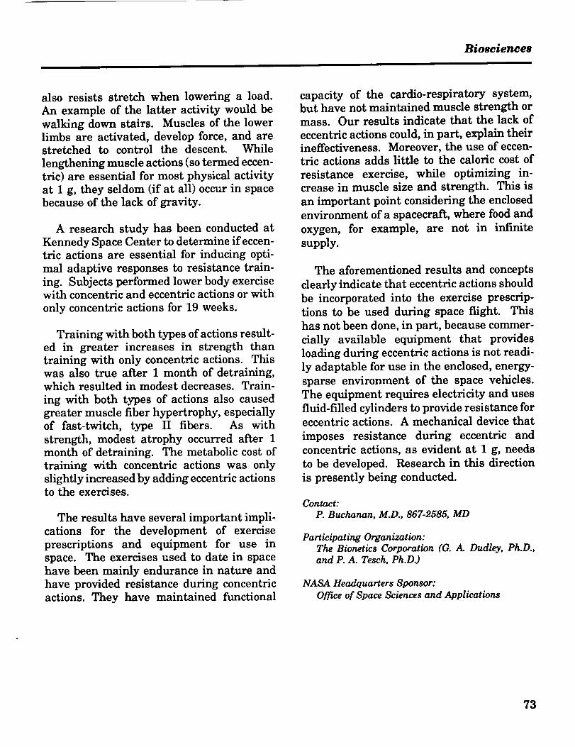
Biosciences
also resists stretch when lowering a load.
An example of the latter activity would be
walking down stairs. Muscles of the lowerlimbs are activated, develop force, and arestretched to control the descent. While
lengthening muscle actions (so termed eccen-
tric) are essential for most physical activity
at 1 g, they seldom (if at all) occur in space
because of the lack of gravity.
A research study has been conducted atKennedy Space Center to determine if eccen-
tric actions are essential for inducing opti-
mal adaptive responses to resistance train-
ing. Subjects performed lower body exercisewith concentric and eccentric actions or with
only concentric actions for 19 weeks.
Training with both types of actions result-ed in greater increases in strength than
training with only concentric actions. This
was also true after 1 month of detraining,which resulted in modest decreases. Train-
ing with both types of actions also caused
greater muscle fiber hypertrophy, especiallyof fast-twitch, type II fibers. As with
strength, modest atrophy occurred after 1
month of detraining. The metabolic cost of
training with concentric actions was only
slightly increased by adding eccentric actionsto the exercises.
The results have several important impli-cations for the development of exercise
prescriptions and equipment for use in
space. The exercises used to date in spacehave been mainly endurance in nature and
have provided resistance during concentricactions. They have maintained functional
capacity of the cardio-respiratory system,
but have not maintained muscle strength ormass. Our results indicate that the lack of
eccentric actions could, in part, explain their
ineffectiveness. Moreover, the use of eccen-tric actions adds little to the caloric cost of
resistance exercise, while optimizing in-crease in muscle size and strength. This is
an important point considering the enclosed
environment of a spacecraft, where food and
oxygen, for example, are not in infinite
supply.
The aforementioned results and concepts
clearly indicate that eccentric actions should
be incorporated into the exercise prescrip-
tions to be used during space flight. This
has not been done, in part, because commer-
cially available equipment that provides
loading during eccentric actions is not readi-
ly adaptable for use in the enclosed, energy-
sparse environment of the space vehicles.
The equipment requires electricity and uses
fluid-filled cylinders to provide resistance for
eccentric actions. A mechanical device that
imposes resistance during eccentric and
concentric actions, as evident at 1 g, needs
to be developed. Research in this direction
is presently being conducted.
Contact:
P. Buchanan, M.D., 867-2585, MD
Participating Organization:The Bionetics Corporation (G. ,4. Dudley, Ph.D.,and P. A. Tesch, Ph.D.)
NASA Headquarters Sponsor:Office of Space Sciences and Applications
73

Autonomous Systems
Autonomous systems research and devel-
opment efforts at the John F. KennedySpace Center (KSC) are focusing on applying
artificial intelligence and robotics technology
to the Space Shuttle's ground processing andlaunch operations. The Artificial Intelli-
gence Laboratory and the Robotics Applica-
tions Development Laboratory are engagedin this application process.
Robotics Applications Development
Laboratory
The Robotics Applications Development
Laboratory (RADL) is used for prototyping
and testing of robotic systems that will be
capable of performing many of the mechani-
cal ground processing functions for the
Space Shuttle and associated payloads.
Elements in the design and evaluation stageinclude stereo and structured laser three-
dimensional vision systems, realtime reac-
tive and adaptive control systems, and a
variety of force/torque and proximity sen-
sors. The integrated RADL system is cur-
rently providing an easy-to-use testbed for
NASA sensor integration experiments.
Advanced target tracking development is in
progress for mating of umbilicals used dur-
ing space vehicle launch. Programmatic
studies are underway to use laboratorycapabilities to enhance the safety, produc-tivity, and efficiency of KSC facilities for
Shuttle and future ground processing opera-
tions. Projects are underway that should
generate large operational cost savings
through the integration of advanced technol-
ogies for ground processing operations, suchas Orbiter tile and radiator damage assess-ment.
Artificial Intelligence Laboratory
The Artificial Intelligence Laboratory
provides the capability to investigate and
develop artificial intelligence/expert systems
technology needed by the Space Shuttleprogram for streamlining checkout and
launch operations. The laboratory serves asa working environment for systems domain
experts and software programmers. It
houses specialized computers (14 symbolic
processors) and 16 general-purpose personal
computers plus peripherals. The laboratory
is involved in the analyses or development of
an intelligent launch decision support sys-tem (launch feasibility management tool)
and a knowledge-based autonomous test
engineer (autonomous control, monitoring,fault recognition, and diagnostics for trouble-
shooting).
74

ORIGINAL PAGE
BLACK AND WHITE PHOTOGRAPHAutonomous Systems
Robotics Applications Development Laboratory
Robotics Applications Development Laboratory
Artificial Intelligence Laboratory =
75

Research and Technology 1990
Orbiter TPS Automation Study under a different program.
A comprehensive study was conducted to
evaluate Orbiter maintenance procedures on
the Thermal Protection System (TPS) and to
select procedures that could be automated
using available robot and sensor technology.
The objectives of the study were to identifyTPS tasks whose automation would be cost
effective and could improve the Orbiter
maintenance schedule and to integrate state-
of-the-art robotic technologies into NASA's
ground operations.
A list of all relevant tasks was compiled.
This list comprised 132 processes fromwhich 19 tasks were selected as candidates
for automation. Preliminary evaluation ofthese tasks narrowed the list to seven tasks
that could be justifiably automated with
available technology. These tasks were then
rank ordered, and the ranking selected the
step-and-repeat tasks (tile rewaterproofingand TPS
anomalydetection)as initial
processes tobe auto-
mated.
Four of the
remainingtasks can
be added at
a later date
with soR-
ware addi-
tions only;one task
would re-
quire a
specializedsensor to be
developed
The study resulted in a conceptual design
for a robotic system capable of moving sen-
sors and specialized tools to inject and
inspect the lower surface tiles. Because the
rewaterproofing tool has to be moved fromtile to tile and because current sensor tech-
nology is incapable of viewing the entireOrbiter underside, a mobile base with an
associated fine-positioning mechanism isrequired to move the tools and sensorsaround in a timely manner. The mobile
base can be semi-automatically or automati-
cally moved into various positions under-
neath the Orbiter and would be capable of
being transported to the appropriate facility
during the refurbishment cycle to perform
work. The system will function by: (1)
accepting user-defined data (e.g., tasks and
regions to work on), (2) performing tasks in
an autonomous fashion, and (3) automatical-
ly uploading the resulting data (e.g., inspec-
Automated TPS Control System Architecture
ENTERPRISE
(HIERARCHIALDATA BASE)
CELL
(OBJECT-ORI ENTEDDATA BASE)
ROBOT
(RELATIONAL
DATA BASE)
76

Autonomous Systems
Automated TPS Processing Mobile Robot
tions, dimensions, pictures, maps, etc.) to
the appropriate data base management
systems.
A 3-1/2-year project plan was developed
that would allow significant demonstrations
of intermediate capabilities of the system
throughout the development cycle. Early
demonstrations will include operator inter-
face displays and tile rewaterproofing and
sensor capabilities. Intermediate demon-strations will include mobile-base move and
fine-positioner capabilities. Early in the
integration, demonstrations of system navi-
gation, positioning, and sensor interactionwill be made with realistic mockups. The
robot will locate randomly selected tiles and
the sensor data will be acquired and dis-
played. These and later demonstrations will
directly support the final goal of complete
integration of a production-qualifiable sys-tem.
The study team concluded that the system
proposed for automating the selected tasksis technically feasible and cost justifiable.
Initial labor hour savings are calculated to
be 630 hours per flow and 2500 hours per
flow on full implementation. Process effi-
ciency savings of several weeks per flow willbe realized for some automated tasks.
Improvements to shop safety, TPS quality,
and paperless documentation will also be
significant.
This will be the first mobile robotic sys-
tem used for Orbiter launch processing.
Development of the system will result in a
nontrivial integration of state-of-the-art
technologies. System development will begin
in January 1991.
Contact:T. A. Graham, 867-4156, DM-MED-12
Participating Organization:Boeing Aerospace Operations, Engineering SupportContract, (J. R. Bledsoe and W. Spiker II)
NASA Headquarters Sponsor:Office of Aeronautics and Space Technology
Payload Processing SystemStudy
The Kennedy Space Center (KSC) is the
operational support base for processing the
Orbiter vehicle and its payloads (cargo) for
the Space Transportation System (STS) to
accomplish specific missions in space. Pay-
load processing at KSC includes the prepa-ration, final checkout, and loading of pay-loads into the Orbiter vehicle before launch
and deintegration of payloads upon their
return from space. A payload is the cargo
77

Research and Technology 1990
\
\
I1_11
I_1
IMI
I_1 _
I_1
I_1
IMi
IN|
I
II!t_ti!
it,|
_J
PCR Washdown Mechanism PCR Vacuum Mechanism
The InterClean Robot
that is designed and built (usually by an
owner other than NASA) specifically for
integration into the Orbiter vehicle at the
Payload Changeout Room (PCR) or the
Orbiter Processing Facility (OPF) at KSC.
More specifically, the Payload Processing
System study was targeted to determine the
requirements and design solutions needed to
support automated payload
processing tasks. The perspec-
tive of the KSC study team was
to identify and propose appro-
priate automation/robotic tech-
nologies and solutions capable
of significantly improving pay-
load processing for the opti-mum mix of human and ma-
chine resources for enhanced
safety, productivity, cleanli-
ness, and cost effectiveness.
Three robotic system solu-
tions were identified and pro-
posed: (1) the High-Efficiency
Particle Accumulator (HEPA)
Filter Aerial Inspection Robot
(HAIR), (2) the Interstitial
Area Cleaning (InterClean) Ro-
bot, and (3) the Multiple-De-
gree-of-Freedom Robot (M-DOF).
HAIR
The HAIR performs the
inspection and certification ofthe clean air HEPA filters in
the ceiling of the PCR. This is
an essential step in preparingthe PCR to meet the environ-
mental parameters. The pro-
posed system is a 4-degree-of-freedom (4-
DOF) robot with three prismatic joints and
one rotational joint (PPRP), designed to
operate on the existing 5-ton bridge crane
rails located at the PCR. This system will
be equipped with sensors and feedback
circuitry to autonomously or semi-autono-
mously control the 4-DOF robot to perform
systematic filter efficiency and leak checks
M-DOF Robot Simulation
78

Autonomous Systems
without damaging the filters orcolliding with existing struc-
tures.
InterClean Robot
The InterClean robot per-forms both the exterior wash-down of the main PCR doors
and the removal of insects from
the interstitial area between
the Orbiter payload bay doorsand the PCR main doors. This
system will incorporate two
vertically translational bases,
permanently installed in theinterstitial area and the wash-
down and vacuum end-effec-
tors. The washdown Inter-
Clean is a 2-DOF robot with
one prismatic joint and one
rotational joint (PR). The vacu-um InterClean is a 3-DOF with
two prismatic joints and one rotational joint
(PRP). The system will be equipped with
adequate sensors, controls, actuators, and
fail-safe features to autonomously clean theinterstitial area.
M-DOF Robot
The M-DOF robot will perform a number
of tasks that require light-duty manipulation
and long reach into a highly restricted work
space. The proposed design is a redundant(greater than 6-DOF) manipulator arm.
This system will perform basic processing
tasks such as inspection, insertion, and
removal of small items. The configuration
will consist of a positioning boom and a
serpentine manipulator. The positioning
boom will provide a base for the serpentine
manipulator and is attached to the PCR
strongback. The boom consists of three
REMOVABLETOOLING
PRISMATIC{BOOMJOiN'r) =IOTATIONAL JOINT ( + 180 o)
HEPA Aerial Inspection Robot (HAIR)
links: a rotary shoulder joint at the base, a
rotary elbow joint between the first and
second link, and a telescopic joint between
the second and third link. This positioning
mechanism will be responsible for position-
ing the serpentine manipulator close to adesirable access window into the payload.
The serpentine manipulator will consist of
three sections: a planar base arm, a planarmidarm, and an end arm that consists of
tubular links moving in three dimensions.
The system will incorporate a number ofadvanced technologies in the area of sensing
(skin), mechanisms, path planning, control,and user interface. The M-DOF will be a 5-
year project with 2 years of research anddevelopment. At the end of 2 years, a feasi-
bility review study is anticipated.
The M-DOF robot presents a tremendous
opportunity to demonstrate advanced manip-
79

Research and Technology 1990
ulation techniques in more complicatedpayload processing scenarios. Due to thefundamentally complex environments sur-rounding payloads and payload processing,a flexible robotic system capable of complexmaneuvers in very constrained spaces will
prove invaluable to inspection, checkout,light manipulations, and general processingof payloads at KSC. In addition to offeringthe advanced capability of redundant de-grees of freedom into automated payloadprocessing, the M-DOF system will no doubtprovide a rich source of systems and compo-nents for technology transfer.
Contact:R. Lewis, 867-4181, DM-MED-12
Participating Organizations:Boeing Aerospace Operations, Engineering SupportContract (G. N. Maliotis)
McDonnell Douglas Space Systems Company
Carnegie Mellon University
NASA Headquarters Sponsor:Office of Aeronautics and Space Technology
Automation of Payload CanisterCleaning
The payload canister is used for trans-
porting mission payloads from several pro-cessing facilities at Kennedy Space Center
(KSC) to the launch pad. The payload is
then installed inside the Orbiter payload
bay. The canister must maintain a clean
interior environment around the payload
throughout transportation. It is required
that the canister interior walls and compo-
nents be cleaned before a payload is in-
stalled. The canister is cylindrical in shape
with a length of about 67 feet and a diame-
ter of about 15 feet. Currently, this cleaning
80
I
process involves the effort of three techni-
cians working for approximately four days.The KSC Robotics Section has studied the
feasibility of automating this process.
After a thorough search and data evalua-
tion, it was determined that there were no
commercially available robots to successfully
perform the cleaning process. A number of
conceptual designs for automating the pro-
cess were investigated; several of these
approaches could be implemented. As the
study progressed, it became clear that canis-
ter cleaning should be approached as an
automation process and not a robotics auto-
mation process. A program has been pro-
posed that emphasizes development of an
automated cleaning system using state-of-
the-art technology.
This approach offers several advantages
to KSC. There are many potential applica-tions for an automated cleaning system, and
this program will develop a generic system
that will have the flexibility to be applied in
other applications. The recommended ap-
proach (see the figure "Proposed Canister
Cleaning Configuration") will minimize risk
and shorten development time. This will
result in a low-cost application that will be
available in a short time frame. Operation-
ally, this system should improve safety and
shorten processing time.
In the next year, engineering design will
commence on the mechanical, electrical, and
control systems. Concurrently, cleaning end-
effectors will be designed, built, and tested.
By the end of the first year, all subsystemswill be built and fabricated. After the first-
year efforts, it is anticipated that anotherfour months will be required to assemble,
test, and certify the complete system.

Autonomous Systems
OPEP_TOR
ARM
TEt E_COPrdGBOOM
_oR
MARKLII_ CHENNY piCKER TRANSPORTER
Proposed Canister CleaningConfiguration
Contact:
R. Lewis, 867-4156, DM-MED-12
Participating Organization:Boeing Aerospace Operations, Engineering SupportContract (A. C. Hiebert and R. P. Bennett)
NASA Headquarters Sponsor:
Office of Space Flight
Orbiter Radiator DamageInspection
Background
NASA Kennedy Space Center (KSC) is
working on a joint project with Lockheed(KSC and Palo Alto organizations). Lock-
heed is developing a sensor system to exam-
ine and inspect the Orbiter radiators for
damage (delamination and meteorite dings)while NASA is developing a robotic mecha-
nism to transport the Lockheed sensor over
the complex contours and 10.5-foot by 60-foot surface of the radiators. A prototype
production system and future productionmodels will be tested, certified, and installed
in the Orbiter Processing Facility (OPF) at
KSC.
The objective of the project is to decreasethe amount of time it takes to process anOrbiter before each mission. The efficiency+
of the radiators to dissipate radiant heat
energy is dependent on their surfaces beingclean and damage free. It presently takes
16 people 24 hours to inspect the Orbiterradiators to determine damage (e.g., dings,
scratches, impacts, etc.) prior to continuingother work in the OPF. A robotic inspection
system should reduce this to two people inthree hours and provide accurate repeatabletrend data and a quality inspection. Cur-rently, the operation is performed with anXYZ mechanism over the Orbiter that moves
"buckets" large enough to carry men and
equipment. The buckets are driven by
highly skilled personnel. The visual inspec-tion is performed using the naked eye andobservations are recorded on a log sheet.
This does not provide an accurate perma-nent record of damages and their locations.
Small imperfections may be overlooked.
This is a very uncomfortable, task-intensive,
repetitive job.
By automating this operation, most of the
personnel would be relieved of their inspec-tion duties so their talents can be used to
perform other jobs more demanding of their
skills. It would also provide a quickly acces-
sible permanent record of radiator inspection
data (damage assessment and precise loca-
tion), reduce the amount of paperwork
81

Research and Technology 1990
required to get the job done, minimize setup
time to get ready for inspection, and provideexpansion capabilities so that other func-
tions could be performed on the radiators
with the automated mechanism (e.g., clean-ing). The overall goal is to achieve an effi-
cient and less expensive operation.
Automatic Radiator Inspection Device(ARID)
The ARID mechanism was an evolution-
ary design culminating in a four-degree-of
freedom robot (see the figure "Radiator
Inspection Robot"). Lockheed originallyenvisioned that the ARID would be a camera
traveling on a contoured beam shaped like
the radiators, transported along two rails
that lie along the edges of the Orbiter radia-tors.
During the design, it became readily
apparent that all these problems could beminimized through a flexible robotic mecha-
nism that could: (1) provide a quick, soft-
ware-programmed "frame shift operation"
eliminating parking offset adjustments, (2)
be cantilevered from under access platforms
located adjacent to the radiator panels and
moved out of the way when necessary so as
to not impact facility operations, and (3) be
reprogrammed or be expanded tn support
Radiator Inspection Robot
other future changes. This robotic flexibilitywill be advantageous for future update ofthe system to allow for cleaning of the radia-
tors by the ARID rather than by men hang-ing over the sides of buckets. In the nearfuture as the use of the robot becomes more
of a standard operation, as people get more
accustomed to using automation, and afterthe ARID proves itself to be reliable, amodification can be made so that it can
actually clean the radiators by "hand rub-bing" the delicate surface.
The first in-house mechanism concept (a
PPRP robot) consisted of a 65-foot prismaticrail to traverse the length of the four radia-tor panels, a prismatic cart to reach from
the outer edge of the door to the Orbiter's
hinge, and another prismatic rack-and-
pinion rail with a rotary joint to move the
inspection device over the contoured surface
of the radiators. However, this configuration
required many closeup pictures and wouldhave produced an excessive amount of data.
The time to process this data would not have
significantly reduced operational timelines.
Therefore, the design quickly evolved into a
PRRR mechanism (see the figure "24-Inch
Inspection Work Space") in which the cables
could be routed within an enclosed space
(bending at the joints rather than being
dragged over the width of the radiators).
Seals can be installed on the joints
to eliminate grease drippings.
Lockheed (the designers of the
payload) requested that NASA KSC
(the robot designers) investigate
designing a mechanism that would
allow taking photos from 6 feet
away. This design would require
that the upper access platforms be
raised and another revolute joint beinstalled to lit_ the nose of the de-
82

Autonomous Systems
(Xo, 138.21,441,81) KU-BAND
ANTENNA
HOUSING
-. ........... ..-""
WORK
ENVELOPE
i ........'(.::
ASSEMBLY
(STARBOARD)
l SPACE SHUTTLE PAYLOAD BAY DOOR
OPEN AT t50 DEGREES POSITION --
24-Inch Inspection Work Space
vice; also, it would have made it difficult to
design the robot to allow for later modifica-
tion so it could reach the radiator surface for
cleaning. However, a 6-foot inspection
proved to be too far away to obtain reliable
photos even with zoom lens. Also, since the
designers did not want the device to hit and
damage the radiators if it fell, it was deter-
mined that a 24-inch inspection distance
would be the required sensing position abovethe surface of the radiators. The link
lengths of the robot were then designed so
the robot could transport the sensor over the
work envelope without hitting the radiators
at its extreme lower position. A mechanical
stop keeps the robot within this work enve-
lope. The link lengths were designed so thestops could be removed later and still be
long enough to reach the surface of the
radiators for any future tactile tasks.
Redundancy Requirements
Since this is the first robot that will be
installed next to flight hardware (and espe-cially since it hangs over the radiator doors),
the reliability of the robot is extremely
important. Recently, several suspendedloads at various NASA facilities have had
mechanical failures that caused them to
drop onto a Spacecratt or flight hardware. If
this occurred at the launch pad, not onlycould an $80 million Spacecraft be damaged,but it would cause an aborted launch. This
produces expensive consequences resulting
in large amounts of serial-time/money to re-
place and repair. The existing inspection"buckets" have even collided with the radia-
tor doors and bent them upward. The robot
has been designed to not hit any of the
radiator panels even in worst-case parkingconditions. However, the robot was also
designed (for future use) so it could actuallytouch the entire surface of the radiators.
When, and if, the stops and mechanical
constraints are removed, the robot control
system must be so reliable that there can be
no inadvertent moves to cause even "dings"
or "scratches" to the sensitive surface. To
prevent this from occurring, the ARID has
been designed so it contains complete control
system component redundancy and addition-
al mechanical constraint redundancy.
Electromechanlcal design of each joint
includes redundant drive shafts, bearings,
harmonic drives, brakes, transmission
chains, encoders, and motors (see the figure
"Redundant Drive Components"). They are
sized for the load, torques, and the space
available in the stowage position. Elec-
trically, the control system includes redun-
dant motor servocontrollers, redundant
indexers, and two separate control comput-
ers. Mechanically, redundancy exists by
83

Research and Technology 1990
adding a special cable/pulley configuration attwo of the joints that would prevent the arm
from colliding with the radiators even if bothredundant brakes or motor drive chainsfailed.
Two motors in parallel could possibly be
expected to "fight" each other, but there is a
400-to-1 transmission gear ratio and a smalltorsional compliance in the harmonic drives
and development in the laboratory hasresulted in synchronous control of redundant
motors. Also, drive components are bal-
anced relative to the load. Therefore, any
noticeable motor torque imbalance caused bycomponent failure will be detected and used
to shut down the system. The internal
motor resolvers are compared against dupli-cate incremental encoders to provide redun-dant sensor feedback to enhance trouble-
shooting by the two computers. Once the
fault is identified, the operator can shutdown one side of the drive, release its brake,
and use the remaining drive to fold the arm
back into its tucked position and stow it in
its "cubbyhole." In the case of a failure that
requires repair of the robot, this will allow
tx\_ <%.\\\\\-,:\x_\\\\,,_ x\\_l
HARMONIC
BRAKE j DRIVE
__.J
! KH - 710
_ ENCODEI
.k_"_."-.\\_
"/ZIIZI//'/://Z//½
Redundant Drive Components
the doors to be closed without having todismantle the robot arm and will enable the
operational workflow to continue. A master
computer and the slave computer each
compare their own calculated kinetic posi-tions, crosscheck positions with each other,
and check sensor feedback before allowingparallel-command moves to continue. Theredundant system will be used in a "fail-
safe" mode. If one computer fails, the othercomputer is switched in as a lone controller
allowing the operation to continue to a safeconclusion.
Simplification is the key to the design.
The rotary links perpendicular to the track
(prismatic link) of the robot will basicallyoperate in a plane. The arm will be posi-
tioned to a location, the joints will be locked,
and then the arm will travel lengthwisedown a panel (using only the motors in the
prismatic axis). Next, the revolute jointswill be unlocked and the arm will be lowered
to another position that extends outwardfrom the Orbiter. Then the arm will be
moved lengthwise again. Photographs will
be taken without stopping as the system
moves at 4 inches persecond. After an auto-
matic scan, the operator
may wish to look again at
an anomaly or take a
"still" photograph. He
then can either program
that position for an auto-
matic move or manually
drive the robot to a point
that requires more resolu-tion.
It is significant to notethat the ARID robot in-
volves the application of
complete control hardware
84

Autonomous Systems
Final ARID Configuration
redundancy to enable performance of work
above and near expensive critical Shuttle
hardware (see the figure "Final ARID Con-
figuration"). There are applications in which
a robot would not normally be used because
of "reliability" or in situations where an
inadvertent move could result in damage to
expensive components or even more expen-
sive personnel. In such applications, the
consumer marketplace may wish to explore
commercialization of these component re-
dundancy techniques.
Contacts:
V. L. Davis, Chau Ba Le, E. Lopez del Castillo,
T. A. Graham, and G. Tamasi; 867-4181; DM-MED- 12
D. J. Minderman, 867-7584, DM-MED-33
A. P. Smith, 867-9120, DF-FED.21
NASA Headquarters Sponsor:
Office of Space Flight
High-Speed Flexible RobotController
With the advent of high-speed sensor
equipment, realtime automated systemshave become more feasible. The Robotics
Section of NASA's Engineering Development
Directorate has undertaken the development
of a high-speed robotic controller that com-
pensates for the realtime response deficien-
cies of commercially available robot control-
lers. Typical controllers are not designed to
respond robustly to streams of realtimesensor data such as vision and force-feed-
back data used to control a robot
manipulator's configuration. This unique
control problem prompted the design of aHigh-Speed Flexible Robot Controller
(HSFRC) capable of meeting the demands of
realtime, sensor-based control for a generic
six-axis industrial manipulator. This system
is required for the purpose of fully realizingthe benefits of automated mating of
umbilicals with flight vehicles. The Robotics
Section has already initiated development of
this realtime control technology and hasestablished a solid baseline of expertise
through relevant analyses, studies, tests,
and the production of a working prototype
system to demonstrate and evaluate this
emerging technology.
The flexibility of this system is found inthe soRware architecture that allows the
user to customize the controller to suit any
system requirements (see the figure "RunTime Control Software").
The servocontrol is done with an integral
term coupled with velocity and acceleration
feedback. This feedback increases accuracy
and reduces overshoot. The servocontroller
also contains a feed-forward gain. This con-
troller takes realtime inputs in world coordi-
85

Research and Technology 1990
MODIFYV/OC
CONTROL MOVE_TO ( ) SYNCHRONIZE TEACH PENDANTROBOT MOVE
EVENTS ROBOT LOOP ERROR
HANDLER
VAX
COMMUNICATIONS
MAILBOX LOGIC .)
FORCE
CONTROL
TO DACP _H_MAILBOXES
MODEL
MAILBOXES
Run Time Control Software
nates and produces a digital servosignal thatis sent to the robot's servos through digital-
to-analog converters. The actual position of
the robot is measured by the resolvers that
are installed at each joint of the robot. This
e
COMMAND
FEED-FORWARD
GAIN
INTEGRAL
GAIN
POSITION
FEEDBACK
e COMMAND
information is used to calculate the velocityof the robot and is fed back to the servo-
control loop algorithm as shown in the figure
"HSFRC Servocontrol Loop." The velocity iscalculated by differentiating the current
VOLTAGE TO
FEEDBACK ! SERVOS
VELOC FrY ESTIMATION
t _Z2+ blZ +b0 IAXIS VELOCITY Z3+ "2 Z2+ alZ + ao
ESTIMATE
<]
HSFRC Servocontrol Loop
RESOLVER-TO-DIGITAL
CONTROLLER
RESOLVER
FEEDBACK
86

Autonomous Systems
I CPU I
MEMORY IMAI LBOX
ELECTRONICS INTERFACE SYSTEM 1LROBOT
MOVE
DATA
SERVO IDRIVE
POWER
DRIVE
RESOLVE
FEEDBACK
ROBOT I
HSFRC Hardware Layout
F()RCE I VISI()N
robot position. This differentiation introduc-
es noise into the calculated velocity; there-
fore, a low-pass filter is placed inline. This
algorithm is used for all joints.
The HSFRC's hard-
ware consists of four
major units: (1) the
Central Processing
Unit (CPU), whichexecutes the servo-
control software, (2) the
mailbox system inwhich all transfers of
data to and from the
CPU take place, (3) the
Data Acquisition Con-
trol Processor (DACP),
which connects the
mailboxes to the interface hardware, and (4)
the Electronics Interface System (EIS),
which takes data from all sensors and sends
data to the robot.
The CPU used for the HSFRC is a Moto-
rolla 68020-based system with a lightning
co-processor. This system runs a realtimeversion of Unix and all servocontrol software
is written in "C." The system mailboxes are
a chunk of main memory allocated for the
purpose of transferring data between theCPU and the DACP. The EIS is the sensordata traffic controller and also decodes the
robot's positional data (see the figure"HSFRC Hardware Layout").
The HSFRC takes inputs from realtime
sensor systems at rates up to 100 hertz and
is capable of sending processed data in worldcoordinates to the robot at a 100-hertz rate,
which increases the control bandwidth from
the current 8 hertz to 100 hertz. The world
coordinate data is calculated at the servo-
control preprocessor from the robot's current
position information fed back from therobot's resolvers (see the figure "HSFRC
Servocontrol Preprocessor").
VISION .._ VISIONPOSITIONAL MOTION
ERROR ALGORITHIM
CONTACT __ FORCE ___FORCES CONTROL
ALGORrrHIM
PREPROGRAMMED J
POINT "_TRAJECTORYGENERATION
ALGORITHIM
CURRENTCOMMAND CURRENTPOSITION COMMAND
POSITION
_" (JOINTX (t) I I COORDINATES)
INVERSEKINEMATICS
I e COMMAND
___ SOF-13NARE-
CONTROLLEDINPUT
SELECTION
,/POSITION
FORWARD _ FEEDBACKKINEMATICS 0 COMMAND
HSFRC Servocontrol Preprocessor
87

Research and Technology 1990
Contact:
Chau Le, 867-4181, DM-MED-12
Participating Organizations:Iowa State University (Dr. R. Fullmer andK. Bigelow)
Boeing Aerospace Operations, Engineering SupportContract (J. R. Lago)
NASA Headquarters Sponsor:
Office of Space Flight
Knowledge-Based Autonomous
Test Engineer (KATE) - A Model-
Based Control and DiagnosticShell
Conventional approaches to developingand maintaining diagnostic and control
process software are time consuming and
costly. Furthermore, the resulting software
may be incomplete and unable to handlesituations that were unforeseen when the
software was written. Significant advantag-
es are obtained by systematically represent-
ing and using knowledge of a system's struc-
ture and function. This concept is also
known as "model-based reasoning." TheArtificial Intelligence Section, Engineering
Development Directorate, at the KennedySpace Center (KSC) is continuing the devel-
opment of realtime knowledge-based diag-
nostic and control systems for ground launch
operations. The project resulting from these
efforts is called KATE. KATE employsconcepts of sensor-based and model-driven
monitoring and fault location and performs
control and redundancy management of
process control systems.
KATE is being designed as a generic,
model-based expert system shell. The main
objective is to provide autonomous control,
monitoring, fault recognition, and diagnos-
tics for electrical, mechanical, and fluid
system domains. KATE incorporates theengineer's reasoning about control and
diagnosis of complex engineering systems in
the form of general software algorithms.
These algorithms are generic in the sense
that they do not contain any domain-specific
information. The algorithms are then ap-
plied to an exchangeable knowledge base(also referred to as a model base), whichdescribes the structure and function of a
specific domain. This knowledge base isessentially a mathematical model of the
particular engineering system to which
KATE is being applied.
Using this domain-specific model orknowledge base, KATE has the capability of
intelligently controlling, monitoring, anddiagnosing faults for the particular applica-
tion. The model produces control operations
and expected values for the hardware sys-
tem's measurements. In addition, it is used
to test diagnostic hypotheses generated asexplanations for observed failures. The
model is automatically updated as the engi-
neering system is manipulated or degrades.
The result is increased machine intelligence
in reasoning about the system's health and
in controlling the state of the hardware
system.
KATE is currently implemented in LISP
and'runs on symbolic processors.
Previous Work
At the Kennedy Space Center, NASA first
developed the LOX Expert System (LES) in
1983 to perform fault detection and isolation
for the process control system that handles
the loading of liquid oxygen into the external
tank of the Space Shuttle. In 1985 with the
addition of control capability, LES evolved
88

Autonomous Systems
into the more generic and robust model-
based system, KATE.
During 1989, KATE was successfullydemonstrated against a scale model of theOrbiter Maintenance and Refurbishment
Facility's (OMRF's) Environmental Control
System (ECS). The OMRF ECS suppliesconditioned air to four different compart-
ments of the Orbiter during processing. Thehardware model of the OMRF ECS contains
a purge unit that supplies chilled air to fourducts that, in turn, supply air to the Orbiter.Each duct consists of a heater for maintain-
ing a constant temperature and a motorizedflow control valve for controlling the flow
rate. A failure panel has been added to
allow for manual failing of various compo-
nents during testing. An operator can
request certain flow and temperature set-
points, and KATE will respond by adjustingthe valves and heater output to achieve the
setpoints. KATE will also identify and
respond to external inputs to the ECS, suchas load changes. In addition to control,
KATE monitors the system, identifying
discrepant measurement values and assign-
ing probable causes. In most cases, control
of the system can continue, especially if the
discrepancy is due to a measurement failure.
KATE's ability to control and diagnose the
ECS model is currently available for demon-
stration.
In February of 1990, the KATE software
was implemented as the Generic ControlSystem (GCS) prototype and was successful-
ly integrated into the Generic Checkout
System. The Generic Checkout System is
composed of a network of Unix-based equip-
ment connected to a physical model of a
Shuttle water tanking system, referred to as
the Red Wagon. KATE-GCS performs con-
trol and diagnosis of chilldown, fastfill,
replenish, and other processes related to
filling the Red Wagon external tank.
This application of KATE was demon-strated on a Texas Instruments ExPlorer II.
Although KATE is designed to operate the
Red Wagon in a stand-alone mode, the
Explorer II functions as a display processorwithin the Generic Checkout System archi-
tecture. Communication to the network is
accomplished via a Unix co-processor housed
in the Explorer II.
Current Activities
The Artificial Intelligence Section is
currently focusing on the following twomajor implementations of KATE: (1) Autono-mous Launch Operations (ALO) and (2)
Liquid Oxygen (LOX) System.
Autonomous Launch Operations. KATE
is being developed under the U.S. Air Force's
Advanced Launch System (ALS) Advanced
Development Program (ADP) as a projectentitled Autonomous Launch Operations.
The objective of ALO is to demonstrate an
autonomous launch control software system
that performs realtime monitoring, fault
detection, diagnosis, and control from high-
level operations requirements. It is part of
an effort to reduce overall launch operation
costs by significantly decreasing process
control software development and mainte-
nance costs and by greatly reducing launch
crew size, human error, and the time re-
quired for fault detection, isolation, and
recovery.
It is expected that an 80-percent reduc-
tion in software development and mainte-nance costs can be achieved by eliminating
application-specific software and automati-
cally generating the required knowledge
89

Research and Technology 1990
bases from computer-aided design/computer-
aided engineering (CAD/CAE) data basefiles.
The launch crew size is expected to be
reduced to one individual per launch subsys-
tem, a reduction of at least 50 percent from
current unmanned launch vehicles, by pro-dding realtime diagnosis and recovery
capability. In addition, it is intended that as
a result of implementing this research, fewer
people will be required to analyze data and
make decisions under stress, resulting in a
reduction of human errors. Furthermore,
the chances of launching on schedule will be
improved as a result of this faster analysisof problems and the reduction of humanerrors.
fault diagnosis, explanation of diagnoses
through the generation of problem reports,
redundancy management, procedure reading,autonomous camera control, single pointfailure analysis (SPFA), and historical data
plotting. Preliminary demonstrations have
already begun against the H20 TankingSystem hardware.
In September of 1991, the ALO project
plan includes taking another step forward by
demonstrating the KATE software against
the LN 2 Tanking System model. KATEdevelopers will be greatly challenged by the
modeling issues and the required KATE
software enhancements surrounding the
control and health monitoring of cryogenicfluid systems.
In order to demonstrate the previouslystated goals, two hardware testbeds, a
Water (H20) Tanking System model and a
Liquid Nitrogen (LN 2) Tanking System mod-el, have been constructed.
In June of 1992, an integration between
the ALO project activities and another
Kennedy Space Center ALS ADP (No. 5504)entitled Remote Sensor/Cable Identifier willoccur.
As a first step in demonstrating the
KATE software for the ALO project, the H20Tanking System model will be used for
realtime monitoring, fault detection, diagno-
sis, and control of fluid tanking systems. As
part of the H20 Tanking System demonstra-
tion objectives, KATE will be required to
perform the following tanking sequences and
operations through its control capabilities:
ullage pressurization, transfer line chilldown
(simulated), main engine chilldown (simulat-
ed), slow fill, fast fill, topping, replenish, fill
circuit drain and vehicle pressurization,
engine firing (simulated), and drainback.
During these H20 Tanking System opera-
tions/sequences, KATE's ability to perform
the following tasks will also be demonstrat-
ed: dynamic modeling of the physical sys-
tem, monitoring, anomaly detection and
In September of 1992, the KATE software
will be demonstrated against a multiple-
subsystem testbed that will include the
existing ECS model hardware, the H20
Tanking System model, and the LN 2 Tank-ing System model. This testbed was de-
signed specifically to demonstrate the gener-
ic control and diagnostic capabilities in amore launch-realistic environment with
KATE software handling a variety of launch
support subsystems. A supervisory-level
KATE will be tasked to handle the higher
level sequencing of the individual KATE-con-
trolled subsystems.
The ALO project plan includes an optional
extension for 1993. If the optional year is
funded, goals of the project include transfer-
ring the KATE software to a conventional
9O

ORrGINAL PAGEBLACK AND WHITE PHOTOGRAPR Autonomous Systems
i
ALO-H20 Tanking System Storage Tank
hardware and software platform and en-
hancing the generic software to run against
a more robust integrated demonstration
testbed, while concentrating on the realtime
aspects of monitoring, control, and diagnos-tics.
The technology transfer for this program
will be accomplished by inviting the ALS
prime contractors to attend project reviewsand demonstrations and to utilize the soft-
ware, where applicable, on their advanced
projects and/or for unmanned launch com-
plex applications. The KATE developers will
act as consultants for the installation and
integration into an operational environment.
The deliverables will be the resulting
generic control, monitor, and diagnostic
software system and tools that will provide
single-point failure analysis and will permit
rapid generation, modification, and verifica-
tion of knowledge bases for future applica-
tions of the software system.
Liquid Oxygen System. Following the
integration of KATE into the GCS architec-
ture, Systems Autonomy activities continued
91

Research and Technology 1990
with the application to KATE to the Shuttle
liquid oxygen loading system. The ongoing
objectives of this project are to incorporate
technological advances in control, monitor-
ing, and diagnostic techniques as well as
lower software development and mainte-
nance cost in the Shuttle ground operationsenvironment.
The KATE-LOX system currently moni-
tors all phases of liquid oxygen loading into
the Orbiter's external tank during fuelingoperations. Discrepancy reporting and a
limited amount of diagnosis are also beingperformed.
Generic utilities provided in the KATE
software shell include data plotting (histori-cal and realtime), online schematics, toler-
ance graphs, and tree displays. Effective
monitoring of the subject domain required
the addition of application-specific systemfunctions such as fill mode detectors, short-
interval sequence timers, and extensions to
realtime measurement tracking. Feedback
from target users was used extensively to
92
KATE ALO-H20 Tanking System Overview
ORIGINAL PAGE IS
OF POOR QUAUTY

Autonomous Systems
KATE Liquid Oxygen
design a graphical representation of the
LOX system overview that incorporates KSC
firing room color-coding convention and icon
representations and the animation of the
flow of liquid oxygen at critical points in the
fill path.
Initial attempts were made to test the
KATE-LOX system in the Artificial Intelli-
gence Laboratory using realtime Shuttle
playback data from the LOX system. This
proved inefficient because playback data is
System Overview
recorded by measurement rather than time,
and use of this data required timely resort-
ing. KATE-LOX is installed on a SymbolicsXL1200 and now resides in the Vehicle
Engineering New Technology Processing
Laboratory. Model validation and system
testing are being accomplished by exercising
the KATE-LOX against the Shuttle Ground
Operations Simulator model of the Liquid
Oxygen Loading System and online monitor-
ing during live launch countdown loading
operations.
ORIGINAL PAGE ISOF pOOR QUALITY 93

Research and Technology 1990
Access to data is performed by an 80486
front-end processor. The 80486 reads LOX-
related information being broadcast over the
KSC Switched Data Network by a software
package known as PCGoal and routes it to a
Symbolics workstation. Currently, a combi-
nation of 284 vehicle and ground measure-
ments are being processed by KATE-LOX.
Development efforts in 1991 will focus on
the completion of the knowledge base, imple-
mentation of control advisories, completion
of the diagnoser, and design of an explana-
tion facility. End-to-end checkout of the
KATE-LOX system in the Vehicle Engineer-
ing New Technology Processing Laboratory
will be followed by installation in firing room
2 at the Launch Control Center and systemvalidation and verification.
Related Activities
Knowledge Acquisition. Currently,KATE's model bases are built by engineers
who have an understanding of KATE's
method of knowledge representation andhave access to the electrical and mechanical
design schematics and design specification
documents for the particular application
domain. The manual generation of a knowl-
edge base is a time-consuming and tedious
task. As a solution, research and develop-
ment involving the automatic generation of
KATE-compatible knowledge bases from
CAD/CAE data base files is underway. In
addition to in-house development, this re-
search task is being addressed through twooutside research projects: the University of
Central Florida (UCF) and Prospective
Computer Analysts, Inc. (PCA).
A research grant to UCF has sponsored a
study to create a tool that can generate
knowledge bases from existing CAD/CAEfiles. Existing data bases associated with
most engineering drawings are sparse,
usually describing only component names,
interconnectivity between components, andminimal functional information. This infor-
mation is directly translatable, whereas
other information required by KATE must
be inferred through the use of intelligent
tools. UCF has successfully demonstrated
the ability to produce an accurate and fairly
robust KATE-compatible knowledge base.
This 3-year research grant officially termi-
nated in August of 1990; however, some
work by UCF continues under a maximum
1-year, no-cost extension. The resultingsoftware tool, referred to as Automated
Knowledge Generation (AKG), and associat-
ed documentation and user guide, is intend-
ed to be analyzed and integrated into exist-
ing KATE software utilities by KATE devel-
opers.
A Small Business Innovation Research
(SBIR) Phase II 2-year contract awarded to
PCA is supporting development of a
CAD/CAE Knowledge Base Development
Tool. Similar to the UCF research grant
activities, PCA's project involves the auto-
matic creation of knowledge bases fromCAD/CAE data base files but is more encom-
passing in its objectives. The proposed tool
will influence the information input to the
CAD/CAE data base by the design engineer.
Furthermore, in order to capture the knowl-
edge required by the model base that is not
directly transferrable from the CAD/CAE
data base, the tool will interface with the
system designer during the design phase.
The overall objective of the project is to
create a tool through which knowledge and
94

Autonomous Systems
information gained throughout the design,
development, and operational use of aCAD/CAE-designed system can be retained
and utilized to develop and maintain knowl-
edge bases for KATE. Phase II will be
complete in July of 1991. At that time, the
resulting tool is expected to be demonstrated
using the ALO-H20 Tanking System model
as its target application.
Simulation. The KATE software devel-
oped forthe Generic Control System proto-
type is currently being enhanced to demon-
strate KATE's capability as a simulation
tool. This prototype is being implemented
on two Symbolics XL1200's and utilizesthe
knowledge base developed forthe Red Wag-
on. In this two-machine configuration,
KATE isinstalledon both processors.In the
firstprocessor,KATE operates in a _agnos-tic and control mode. KATE also runs on
the second processor but simulates actual
hardware, or in this case,the Red Wagon.
Possible uses of this tool include simula-
tion of ground support systems and Space
Station flight hardware systems for software
component checkout and launch team train-
ing. Concepts presented by this type of
simulation may also be included in a generic
simulation prototype currently being devel-
oped at KSC in support of "core" software
requirements for Checkout Control and
Monitoring System II and Test Control and
Monitor System.
Space Station Applications. In October of
1989, funding was granted from the Space
Station Advanced Development Program to
prepare KATE for delivery to the Space
Station environment. This project is re-
ferred to as the Autonomous Control System
(ACS) and its main objective is to implement
KATE on a conventional, space-rated hard-
ware platform in both LISP and Ada.
The ACS task suffered a severe funding
cut as a directresultofSpace Stationbudget
reductions in 1990. Consequently, the
decrease in availablemanpower and lack of
development hardware led toa restructuring
of the projectplan. LISP porting activities
to the Compaq 80386 and development ofthe user interface for the 80386 were de-
layed in 1990 and completion rescheduled
for mid-1991. Implementation and demon-
strationof KATE in Ada were slipped from
1991 to 1992.
A Functional Requirements Document
(FRD) and a Performance Test Plan (PTP)
were developed in 1990. The FRD baselines
the version of KATE to be implemented on
the 80386 in both LISP and Ada. The PTP
contains performance criteria and methods
for conducting and evaluating system perfor-
mance tests. Performance testing of the TI
Explorer H LISP version of KATE was
completed in 1990.
Other milestones for 1991 include produc-
ing a detailed design document, which will
guide the development of an Ada version of
KATE, and gathering system performance
data on KATE running in LISP on the
80386.
Summary
The development of KATE and its associ-
ated concepts is ongoing. With each new
application of KATE, software enhancementsare made to enable KATE to become more
generic and robust so that it is capable of
95

Research and Technology 1990
handling a wider variety of complex engi-
neering systems.
Contacts:C. L. Belton, B. L. Brown, J. E. Galliher, andP. ,4. Mullenix; 867-3224; DL-DSD-23
Participating Organizations:Boeing Aerospace Operations, Engineering SupportContract
McDonnell Douglas Space Systems Company,Payload Ground Operations Contract
University of Central Florida
Prospective Computer Analysts, Inc.
NASA Headquarters Sponsor:Office of Aeronautics and Space Technology
Remote Umbilical Plate
Docking/Insertion
Realtime adaptive control is a necessary
tool for tracking a Shuttle vehicle that rocks
in the wind while stacked at the launch pad
at Kennedy Space Center (KSC). This
adaptive control is necessary in order to
dock and insert umbilicals (consisting of a
ganged connection of electrical and cryo-
genic/hypergolic fluid lines) without damageto the vehicle and without hazardous leaks.
This reduces reconnect times of 17 to 34
hours to less than 15 minutes and elimi-
nates hazards associated with umbilicals
that would otherwise have to be connected
at launch.
The KSC environment is demanding; the
system must withstand heavy acoustical
shock and see through fog caused by the
dumping of thousands of gallons of water
onto the flames of the Shuttle main engines
(conditions that exist right after an abortedlaunch when an umbilical reconnect would
take place). These shock and blast condi-
tions rule out sensitive laser tracking. The
prototype system being developed at KSCcan be upgraded quite easily for this envi-
ronment. For instance, an infrared filter
can be added to the charge-coupled device(CCD) camera and the five dots can be
changed to infrared light emitting diodes
(LED's) to see through the water vapors
without affecting the system architecture or
changing the extensive soRware algorithms.
Speeds at which a target can be blurredare being tracked. The state of the art has
been advanced at KSC by developing algo-
rithms and packaging off-the-shelf imaginghardware into process machines that signifi-
cantly reduce the blurring of moving targets
to allow for more precise and smoothertracking.
Adaptive control (trajectory perturbationbased on realtime sensory feedback) with
heavy inertial loads is being studied. At
KSC, engineers are attempting to precisely
position 5,000-pound umbilicals (200 pounds
initially) with pneumatic counterbalances onfuture heavier umbilicals. Research in
industry has been conducted on compliance-
aided insertion of resistors into millimeter-
tolerance holes; however, at KSC, heavy
umbilicals (oriented perpendicularly with
respect to gravity) are being inserted into
millimeter-tolerance holes on an object
randomly moving with wind-induced pertur-
bations. This induces high torques into
servocontrol motors, and stability has beenobtained under these extreme conditions.
The Robotics Applications Development
Laboratory (RADL) prototype system con-
sists of a vision-based six-degree-of-freedom
(6-DOF) tracking system attached to the
ASEA robot and a target attached to a sepa-
96

Autonomous Systems
rate receptacleplate. Using a passive com-
pliance end-effector,the robot is able to
track and insertan umbilical plate mockup
(which incorporates fluid, electrical,and
data lines) into a receptacle plate mountedon a 3-DOF device that simulates the motion
of the Orbiter (see the figure "Remote Um-
bilical Mating With Dynamic Simulator
Target"). The passive compliance device
uses nontactile vision tracking and is beingaugmented by a high-speed flexible robot
|1
Remote Umbilical Mating With DynamicSimulator Target
controller, which will provide direct access to
each joint controller and provide 6-DOF
adaptive control capabilities in realtime (30-
hertz control updates for vision and 100
hertz for force-torque tracking).
Enhancements include the use of a coun-
terbalance mechanism that removes loads
from the robot and enables the robot to
disconnect from the umbilical after mating.The robot will be turned off and the umbili-
cal will free float with the counterbalance
removing loads from the vehicle. This re-
duces vehicle design weight and allows more
payload to reach space at reduced costs. A
floating plate is also incorporated that re-
duces insertion loads, reduces connect/
disconnect surges, and eliminates galling ofsensitive cryogenic fluid coupling surfaces.
Improvements also have been made inalignment and capture mechanisms to re-
duce forces, reduce galling, and ensure
positive latching.
6-DOF Tracking
A major innovation is a robotic vision
subsystem that measures the relative posi-
tion and orientation of a specially designed
target and provides realtime control to a
large robotic mechanism. The subsystem
uses standard image processing algorithms
implemented directly in circuitry instead ofcomputer programs that consume more time.
This feature makes it possible to extract
complete sets of target tracking data fromsuccessive image frames at the rate of more
than 30 frames per second.
A solid-state video camera views the
target, which consists of five bright or reflec-
tive circles, four located at the corners of a
square and the fifth located at the center of
the square but 'offset from the plane of the
square (see the figure "Tracking Camera/
Target"). The raw image data is sent to
image processing circuitry that performs a
convolution difference-of-Gaussian edge-
analysis filtering operation to clarify the
picture elements representing the edges of
the circles. On the Shuttle, the fifth circle
could be implemented simply as a styrofoam
thread-spool glued in the center of four
painted circles.
97

Research and Technology 1990
ORIGINAL PAGE'
BLACK AND WHITE PHOTOGRAPH
The image is then processed further to
obtain the centroids of the five circles. The
locations of these centroids relative to each
other and to the overall image frame are
processed to obtain three Cartesian coordi-
nates of the target relative to those of the
camera. Triangulation calculations based on
the vector relationships among the locations
of the five circles and the central axis of the
target yield the roll, pitch, and yaw angles
that describe the orientation of the target
TARGET__1
Note:
The five bright circles of the target are positionedin such a way that the video images of them can be
processed into data on the position and orientationof the target relative to the camera.
Tracking Camera/Target
relative to the line of sight and the field of
view of the camera (see the figure "6-DOF
Target Discrimination in the RADL"). Thus,
the relative position and orientation of the
target are determined in all six degrees of
freedom (see the figure "6-DOF Robot Target
Tracking"). The offset of the central circle
from the plane of the other four circles can
be increased or decreased to increase or
decrease the sensitivity of the subsystem to
the pitch and yaw of the target and to pro-
6-DOF Target Discrimination in the RADL
vide more accurate distance-to-the-targetinformation.
The output data may have to be trans-
formed into spherical or other coordinates
6-DOF Robot Target Tracking
98

Autonomous Systems
used by any other robot. However, thistransformation can be performed easily insoftware. If the robot is changed, it is neces-
sary only to change this software.
Contact:
E. Lopez del Castillo and V. L. Davis,867-4181, DM-MED-12
Participating Organizations:Boeing Aerospace Operations, Engineering SupportContract (J. R. Bledsoe, R. P. Bennett, J. R. Lago,A. C. Hiebert, and A. H. Ladd)
Adaptive Automation, Inc. (Dr. P. Walsh)
NASA Headquarters Sponsor:Office of Aeronautics and Space Technology
Torque Sensing End-Effector
(TSEE)
The TSEE was produced from a SmallBusiness Innovation Research (SBIR) project
to develop an "intelligent" tool/gripper to
open or close valves during hazardous main-
tenance or emergency work. The TSEE fea-
tures servocontrol of jaw-opening dimen-
sions, nontactile/tactile sensors, and torquefeedback to determine and maintain opti-
mum seat pressure settings. This feedback
provides reflective force feedback to an
operator and to automatic computer-con-
trolled operations enabling determination of
valve position and preventing damage to
valve seals. A Phase I SBIR produced a
small working model and a Phase II SBIR
(see the figure "Large Phase II TSEE")
produced a hardened mechanism with a
user-friendly data base capable of operating
in hazardous NEC Class I, Division I, Group
B, hypergolic/cryogenic environments.
The TSEE's interchangeable gripper can
locate a valve position and rotate continu-
ously to open or close valves ranging from
either 0.5 to 4.0 inches or 3.5 to 6.0 inches
in size. Valves can be opened that have a
torque range of 10 to 150 inch-pounds. The
TSEE has a unique nontactile torque sensor
utilizing magnetoelastic phenomena.
The end-effector is used in conjunction
with a computer controller that can inter-
pret commands from an operator at a com-
puter keyboard, from a parallel digitalinterface on the robot carrying the end-
effector, or from a serial communicationslink to another computer. This lets the
system open and close valves and determineif the valve is turning as expected from any
of these operating modes.
The computer that controls the end-effec-tor stores information about a range of
valves whose positions need to be adjusted.
Valves are identified to the system by labels
that may be descriptive or numeric. Infor-
mation in the valve data base is used to
Large Phase H TSEE
ORIGINAL PAGE
BLACK AND WHITE PHOTOGRAPN 99

Research and Technology 1990
identify valves and to provide information on
turning ranges, gripping forces, valve handle
sizes, and current status or position of the
valves. Once valve configuration informa-
tion has been put into the system, opera-
tions of the valve will automatically updatethe data base.
A TSEE can be incorporated with the six-
degree-of-freedom target tracking system to
allow a remote operator [Space Station
astronaut, Flight Telerobotic Servicer (FTS)
remote controller, nuclear cleanup engineer,
or fire fighter] to: (1) position or teleoperate
the robot in front of a panel where it can see
the target, (2) let the target tracker autono-
mously orient the robot at the correct angle
and distance from the panel, and (3) activate
a stored program to perform pretaught
routines. The TSEE locates valves (which
may be in the wrong position with stems in
or out) through simple sensors and then
performs pretaught operational sequences to
"safe" an operation in a hazardous environ-
ment. This can be done with existing tech-
nology rather than waiting for telerobots to
incorporate artificial intelligence to perform
"smart" autonomous operations. This prod-
uct can also enhance robotic applications in
NASA and industry without redesigningexisting valve panel facilities for robotics. It
will provide safer and less serial-time opera-tions in hazardous environments.
Contact:
Chau Ba Le, 867-4156, DM-MED-12
Participating Organizations:Automated Dynamics Corporation (E. Hauber)
Boeing Aerospace Operations Engineering SupportContract (J. C. Windharn)
NASA Headquarters Sponsor:
Office of Space Flight
Intelligent Launch DecisionSupport System (ILDSS)
The overall objective of the ILDSS Projectis to develop prototypes of tools for thelaunch, team that support decisionmakingduring Shuttle launch countdowns. The
specific objectives of ILDSS were determined
in a feasibility study performed in the sum-
mer of 1988 by Arthur D. Little, Inc. The
objectives identified were time management,
anomaly management, and verbal capture.
Time management by the NASA Test
Director (NTD) during terminal count was
the first objective chosen for prototyping.
The first phase of the time managementproject focused on a Time Management
Integrated Display (TMID). The TMID
provides a substrate for all the successive
phases. A conceptual prototype was devel-
oped in 1989 and a realtime field prototype
was developed in 1990.
The realtime field prototype has been fieldtested against Shuttle countdown simula-
tions, terminal countdown demonstration
tests, and launch countdowns. The follow-on
phases (of situation annunciation, interac-
tive "what-if," and advisory capabilities in
terms of situation action and reactive plan-ning) that were planned in 1990 were de-
ferred until 1991 in order to develop the
unplanned realtime field prototype. The
decision to develop the realtime field proto-
type was made when realtime Launch Pro-
cessing System data became available exter-
nal to the launch environment. Technology
transfer of the realtime TMID field proto-
type into the launch environment and into
the Checkout, Control, and Monitor System
II portion of the Common Operational Re-
search Equipment (CORE) Project is
planned in 1991.
100

Autonomous Systems
Operational use of Launch Commit Crite-
ria (LCC), a subset of anomaly management,
was the second objective chosen for proto-
typing. This project will begin in 1991. _No
work is currently planned for verbal capture.
TMID
Time management by the NTD simplisti-cally consists of those decisions required bythe extension of the T-9 minute hold or
invocation of an unplanned hold at one of
the remaining hold points. This requiresmaintaining mental models of the dynamic
state of the countdown and managing theprocess that determines when to resume the
count. The TMID integrates information
currently available on firing room clocks and
hard-copy timelines and correlates the
information graphically in realtime.
The figure "Prototype Overview of the
ILDSS" is a black and white print of a color
screen from the realtime TMID field proto-
type. It depicts the end of theSTS-41 countdown just after
entering the 10-minute holdat T-9 minutes.
the "now" bar, select a mission profile, quit,and start over.
Each row of the UT timeline represents 1minute of UT and is labeled in UT with the
starting time for that minute. There arethree windows that are not labeled. From
left to right, the windows are the resumewindow, the launch window, and the auxilia-
ry power unit (APU) runtime window.
The resume window uses green, yellow,and red. It is displayed in UT but is depen-dent on CDT, the launch window, collision
avoidances (COLA's), and APU run time.This window is enabled after T-20 minutes
and counting and is active when there is ahold pending and when there is a hold. It is
not active when CDT is counting and there
are no holds pending. The colors are used intraffic-light fashion to indicate the situation
if the count were resumed at that point in
the timeline. Green (go) indicates that if the
count were resumed at that point in the
The TMID screen consists
of vertical timelines, a hori-
zontal "now" bar, clocks, and
commands. The timelines are
Universal Time (UT) and
Countdown Time (CDT). The
"now" bar at the top corre-lates the timelines. The
clocks are UT, CDT, Time to
T-0, Hold Time Remaining,
Time in Hold, Window Re-
maining, APU Hold Time,
LOX Drain Time, and Project-ed T-0. The commands are
toggle automatic scrolling for Prototype Overview of the ILDSS
ORIGINAL PAGE ISOF POOR QU$_!.ITY
101

Research and Technology 1990
timeline, then projected T-0 would fall with-
in the launch window, would not fall within
a COLA, and full APU contingency run time
would be available. Yellow (caution) indi-
cates that if the count were resumed at that
point in the timeline, then projected T-0
would fall within the launch window, would
not fall within a COLA, but full APU contin-
gency run time would not be available. Red
(stop) indicates that if the count were re-
sumed at that point in the timeline, then
projected T-0 would either fall past the endof the launch window or within a COLA.
The launch window uses blue. It is de-
fined directly in UT without any dependen-
cies. COLA's appear within the launch
window in red and are also defined directly
in UT without any dependencies. This
window is always enabled and active.
The APU runtime window uses cyan,
green, and yellow. It is displayed in UT butis not anchored in UT until the APU's are
started. It depends on CDT until that point
and will slip accordingly when holds are
extended or unplanned holds are invoked
prior to APU start after T-5 minutes. The
window changes from cyan to green and
yellow aider APU start. Green indicates the
nominal time to T-0 and yellow indicates the
APU contingency run time. This window is
always enabled and active.
Each row of the CDT timeline represents
I minute of UT. Each row is labeled in CDT
with the starting time for that minute.
Labels for holds are in yellow and have an H
suffix. There are no windows. Ground
Launch Sequencer milestone events are
shown as text in the minute in which they
are planned. Events are shown in white
initially and then switched to cyan to indi-
cate that they have occurred based upon the
appropriate function designator status.
When a hold is extended or an unplanned
hold is invoked, it is possible for a row in
the timeline to represent more than 1 but
less than 2 minutes of UT. It will always be
in the past so that each row in the future
will always represent 1 minute of UT.
In order to represent "now" on the time-
lines, a "now" bar is drawn horizontally
across both.timelines for correlation of the
two. The "now" bar is equal to 1 minute of
UT. The idea is to position the bar so the
current UT is within its boundary. When
enough time has passed so that the current
UT is no longer within the "now" bar, it is
moved down the timelines to the next min-
ute.
The clocks are numeric displays of three
types: (1) time-of-day, (2) contingency, and
(3) countdown. Clocks with firing room
analogies act similarly to their firing room
counterparts and are marked parenthetically
with FR. Time-of-day docks display Julian
day and 24-hour time. Time-of-day clocks
are UT (FR) and Projected T-0. Contingency
docks display unsigned time as 24-hour
time. They count down and then count up
when they reach zero. Counting is enabled
and disabled depending upon events. The
amount of time displayed on a particular
clock varies from hours to minutes. Contin-
gency clocks are Hold Time Remaining (FR),
Time in Hold, Window Remaining (FR), APU
Hold Time (FR), and LOX Drain Time.
Countdown clocks display signed time as
daytime and 24-hour time. They also count
down and then count up when they reach
zero. Counting is enabled and disabled
depending upon events. Countdown clocks
are Time to T-0 (FR) and CDT (FR).
102

Autonomous Systems
Development
The conceptual prototype development hasbeen done on Symbolics 36XX LISP ma-
chines with high-resolution monochromemonitors in Common LISP and Flavors
under Genera 7.2. The field prototype
development has been done on 286 and 486
personal computers (PC's) with EGA mode
color monitors in Microsoft Quick C 2.5
under DOS and uses the same hardware and
software development environment as PC
GOAL. The field prototype resides within acustomized version of PC GOAL software.
PC GOAL is a project that provides a facilityfor developing GOAL-like data-driven dis-
plays that can be run in realtime againstLPS data with a GOAL-like user interface.
Contacts:
A. E. Beller, 867-3224, DL-DSD-23F. J. Merlino, 867-4735, TP-VPD.1J. Simon, Jr., 861-2910, TV-PEO-2
Participating Organization:
Boeing Aerospace Operations, Engineering SupportContract (H. G. Hadaller and M. J. Ricci)
NASA Headquarters Sponsor:Office of Space Flight
103

Communications and Control
Fiber Optics1 Communications, andNetworks Laboratory
The Fiber Optics, Communications, and
Networks Laboratory has been expandedduring the last year to include a Networks
Development group. The Fiber Optics andCommunications group provides engineering
support for the John F. Kennedy Space
Center (KSC) copper and optical fiber cables.
The major share of its human and material
resources is assigned to the evaluation and
application of state-of-the-art fiber opticscommunication technology: _ This includes
fibers, connectors, splicing techniques,electro-optical receivers and transmitters,
and multiplexing. Three other significant
laboratory tasks are: (1) maximizing the
utilization of the existing fiber optic and
copper cable plant; (2) providing the techni-cal expertise and hardware for the video and
photo-optical systems used in support of
KSC technical operations; and (3) defining
and furnishing test equipment necessary forthe maintenance of communications, video,
and photo-optical systems.
The networks section of the Fiber Optics,Communications, and Networks Laboratory
is dedicated to a wide range of computer-network-related activities. This area serves
as the primary operations hub and networkcontrol center of the KSC data network. The
majority of all network monitoring, trouble-
shooting, and support is performed from this
location. This laboratory is also responsible
for the evaluation and application of ad-vanced network systems technologies. These
technologies are intended to provide the
most efficient utilization of the cable plant
and the maximum possible support to thenetwork users at KSC.
104

Communications and Control
!
Prototype Fiber Optic TV Camera ProjectControl Terminal
Camera�Pan-Tilt Units Connected by
17 Kilometers of Single-Mode Fiber
With Successful Operation
OR;GJN._L PAGE 105_LACK AND WHITE PNO[OGR,e, pFt

Research and Technology 1990
Fiber Optics, Communications,and Networks Laboratory
General
The Fiber Optics, Communications, andNetworks Laboratory provides engineeringsupport for the optimization of copper andoptical fiber communication links at the
Kennedy Space Center (KSC). During thelast year, the capability of supporting net-works has been added to what used to be
known as the Fiber Optics and Communica-tions Laboratory. The major share of itshuman and material resources is assigned to
the evaluation and application of state-of-the-art fiber optics communication technolo-
gy. This laboratory defines and furnishes
test equipment necessary for the develop-
ment and evaluation of communications,
video, and photo-optical systems. Accep-
tance testing of new technologies to be used
in support of KSC technical operations,
including individual fiber optic components,
is a task accomplished by the Fiber Optics,
Communications, and Networks Laboratory.
This laboratory has been involved with the
development of the next generation of vari-
able-rate, high-speed data links.
Variable High-Data-Rate Fiber Optic Link
Development
The need for variable high-data-rate fiber
TX TERMINAL
BERT "I-X
ANRITSUME522A
CLOCKi..=
5o OHM COAX
DATA
5O OHM COAX v
W/LRCVR/DRVR
100112
W&
RCVR/DRVR
100112
mm
OTX
DlV192
DTX -200
OTX
DM92
DTX-200
SINGLE MODE
FIBER TEST LINK
WDM
RX TERMINAL
ORXSUMITOMO
DM57 mW,'L
RCVR/DRVR
100112
W&RCVR/DRVR
ORXSUMITOMO
DM57100112
WDM
CLOCK i
5O OHM_ _
DATA
i 5OOHucoax _1
BERT RX
ANRtTSUME522A
CLOCK i
5O OHM CC¢=X _11802
DIGITALSAMPLING
' DATA O 'SCOPE
50 OHM COAX _ !
DC to 150-Mb / s Single-Mode Fiber Optic Test Link
106

Communications and Control
optic links at KSC has been increasing over
the past few years to support the Space
Station Processing Facility (SSPF) require-
ments. The Fiber Optics, Communications,
and Networks Laboratory has designed and
fabricated a fiber optic data link that willoperate at any data rate between 0 and 150
megabits per second. The system consists of
two rack-mountable units with two indepen-dent channels to accommodate data and
dock. To provide such a wide variability of
data rates, the docking information must be
sent along with the data. The system was
designed to operate on single-mode fiber due
to modal noise and jitter considerations.
One of the major design goals of high-
data-rate systems at KSC is to keep the
jitter under 5 percent. Such a low jitter was
accomplished using optimized 100K series
emitter-coupled-logic (ECL) circuits: The
electronic portion of this system will transfer
data at up to 585 megabits per second. The
laser drivers, PINFET receivers, and disper-sion characteristics of the fibers are the
limiting factors. The units were field tested
with fiber distances of 8.8 and 15 kilometers.
The jitter remained under the desired 5
percent when the optical energy on thereceiver remained above minimum sensitivi-
ty levels. Two different optical sources were
tested successfully. No errors were detected
during the field test at data rates of up to
200 megabits per second. This system
provides the user with a transparent link so
that whatever goes in will come out the
other side, which will allow an end user
complete flexibility utilizing any protocol.
In order to consider configurations whereonly one optical fiber would be needed,
wavelength division multiplexing (WDM)
was tested. A system was designed to put
two wavelengths (1300 and 1550 nanome-
ters) on one fiber and separate them at the
receiver side. The results are preliminary at
this point; however, there are some situa-
tions where the WDM approach would prove
an adequate solution. The longer wave-
length (1550 nanometers) does exhibit someundesirable jitter characteristics on fiber
that has the zero dispersion point designed
to be at 1310 nanometers. This jitter can be
within the desired goal if the fiber length islimited.
This prototype system is in the process of
being repackaged into a chassis with redun-
dant power switching units and vertical
mounting of the communication channels.
Due to the unusually high data rates in-
volved, the development of a mother board is
critical and has slowed the work. Next year,
however, it is expected that the repackaged
vertical mount chassis will be complete.
The Fiber Optics, Communications, and
Networks Laboratory is also developing a
variable high-data-rate fiber optic link that
will operate at 0 to 1.2 gigabits per second
for distances of 330 meters. This systemwould be used to link computer systems in
the same building such as the SSPF. Con-
cept studies, analysis, and circuit designhave been completed. The parts are being
procured and will be available for prototypefabrication &1ring the upcoming year.
Contact:
P. T. Huang, 867-4548, DL-ESS-12
Participating Organization:Boeing Aerospace Operations, Engineering Support
Contract (F. H. Galloway andR. W. Swindle)
NASA Headquarters Sponsor:
Office of Space Flight
107

Research and Technology 1990
Direct Fiber to Operational
Television Camera System
The Fiber Optics, Communications, andNetworks Laboratory is participating in the
development of a television camera system
that will be the prototype for the next gener-ation of an operational television (OTV)
system camera for use on the launch pad.
The OTV system at the Kennedy SpaceCenter (KSC) provides realtime and recorded
visual information necessary to conduct anddocument hazardous and nonhazardous
activities during daylight and nighttime
operations involving buildup, integration,
launch, and landing of the Space Transpor-
tation System. This engineering and safetyinformation must be of the highest achiev-
able quality. This quality must be sustained
without material degradation and during
duplication, development of training aidsand materials, engineering evaluation, and
analysis for the detection, investigation, and
correction of anomalies. To that end, each
element of the system must meet the maxi-
mal performance criteria to ensure optimum
overall picture quality and resolution.
The existing OTV system (refer to the
figure "Existing OTV System") consists of a
mixture of color, monochrome, and infraredtelevision cameras. Television cameras with
a scan rate approved by National Television
Systems Committee (NTSC) are presentlyused to monitor launch operations. At the
launch pad, these cameras are connected to
camera control units in the Pad Terminal
Connection Room (PTCR) via TV-39 multi-
core camera cable. The camera control units
contain built-in video equalizers to compen-sate for loss in transmission on this cable.
The video output from the camera control
units is connected to a frequency modulation
radio frequency (FM-RF) modulator; the
radio frequency outputs of these modulatorsare combined onto coaxial trunk cables. The
trunk cables proceed through numerousrepeater stations to the Launch Control
Center (LCC). In the LCC, the radio fre-
quency signal from these trunks passes
through a splitter to individual demodula-
tors. The demodulated video signal is then
fed to a video routing switcher for distribu-
tion to the end users, to recorders for docu-
mentation of launch operations, and to theNASA Select channel for use at other NASA
centers.
The prototype OTV camera system (refer
to the figure "Prototype OTV System:')consists of a color television camera at the
launch pad connected to the camera control
unit in the LCC via a single fiber optic cable,which is utilized for bidirectional transmis-
sion of video, synchronization, control, and
status signals. This prototype eliminates
the necessity of equipment for camera con-
trol and synchronization at the launch pad
and eliminates the requirement for repeaters
between the launch pad and the LCC. The
camera control unit and the camera head
each contain a fiber optic transmitter and
receiver connected to the optical fiber via a
wavelength division multiplexer. Signals for
synchronization and control of the camera
and control of the pan-and-tilt head are
transmitted from the camera control unit to
the camera head on one optical wavelength(1330 nanometers), while the camera's video
output and status information are returned
on the same fiber utilizing a different wave-length (1550 nanometers).
The prototype system is being used to
study analog transmission of component
video versus analog transmission of compos-ite video from the camera. Future tests will
108

Communications and Control
llllWlJllllllllmllll_
PADCAMERA HOUSING
!
II II II w-m II
I c_.E I
_I
i- __,o_7_ AECEIVIER I J8
II ,___,:__o_"" .....
_J F_v7 F_-._--I .___---'1 E_IAL_7 I ,o I--
"---- I I"o*Rol J3
J4 IJ13 4
,imllmlll_
_M I
_OEO 1 "ODUL"I I ... TEST1AI_ I--I_S)
'DELAYED T_T T
8YNC
4V P-P
ALL OTHER
CAMERAS I
V_IAI_.E DELAY I
PULSE DISTRIBLmON SYNC 4V P-P
sYSTEM
III @II
LEIT6H TB J ! ®
N Ii®
r- ...... LCC ROOM 1P2CAMERA CONTROL
I
® _ ' ' I I"_,7' I
PAoA I .," d V,OE_O_----_,-,,, o..'r, o_. o_. I _.-._1 " " .--.-__ I I ...,w I
, _ s I q 2 I I "1DE_ TESTI "1 o_/ _ PFE_E'WIP-" _ L,-/
PAD B I
® ' CO(.C_ COMPARATOR
i__ _31 1 I B_CK / _ LEn_SYNCCOLORS_NAL tREF) CSC46S
I®®
Existing OTV System
concentrate on digital transmission of video
over fiber.
A series of tests of the existing and proto-
type television transmission systems wereconducted to evaluate the potential benefits
of fiber optic transmission for OTV signals
used in monitoring and documenting launch
processing operations at KSC. These tests
supplied both subjective and objective data
on the benefits of improvements in thistransmission media to the monitoring of
launch processing operations. Some of the
measured improvements attributed to fiber
optic transmission include: (1) an increase inthe resolution of the camera signals from
approximately 400 lines to in excess of 800
lines, (2) a decrease of distortion attributable
109

Research and Technology 1990
t--
PAD"1
CAMERA HOUSING |
-J
FIBER OPTIC UNK
"1
J3J4
I
LCC ROOM 1P2
RS-2_. L
Prototype OTV System
to a differential phase from 2 degrees to 0.5
degree, (3) a differential gain from 2 percent
to 1.5 percent, and (4) an improvement in
the signal-to-noise ratio from 56 decibels to69 decibels.
The project is also using the prototype to
study the potential of and the requirements
for a new camera control system utilizing a
host central processor and local area net-
work to provide control, monitoring, and
fault reporting for the OTV system. While
microprocessor-based systems for camera
control are used in the existing OTV system,
the camera interfaces
are primarily hardwarebased. This situation
results in system limita-
tions on the type, num-ber, and compatibility ofcontrol functions that
can be interfaced. The
prototype system usesserial data communica-
tion with a micropro-cessor-based camera to
maximize the ability toaddress and control
camera functions. The
prototype system soi_-ware has been written in
C language. The soil-
ware provides the useraccess to and status
reporting of the camerasystem functions, includ-
ing control of the cam-
era, lens, pan-and-tiltmechanism, and lighting
system and remote mon-
itoring of the pressure in
the camera housing,
pan-and-tilt housing,and light assemblies.
Contact:
J. E. Kassak, 867-4548, DL-ESS-12
Participating Organizations:Boeing Aerospace Operations, Engineering SupportContract (F. H. Galloway andJ. E. Brogdon)
Lockheed Space Operations Company,Processing Contract (C. D. Smith andR. E. Niedermeier)
Shu_
NASA Headquarters Sponsor:Office of Space Flight
110

Meteorology
Atmospheric Science Field Laboratory
The Atmospheric Science Field Laboratory
was established at the John F. Kennedy
Space Center (KSC) to provide a focal pointfor thunderstorm and lightning studies. The
laboratory has the tools and expertise todelve into all aspects of lightning phenome-
na, including measurement of electric and
magnetic fields, space charges, and lightning
current densities. Data produced by thelaboratory's research efforts are used to
improve forecasting accuracies, design light-
ning detection equipment, and optimizelightning protection facilities, equipment,
and personnel through the use of physicaland mathematical models. The latest re-
search programs supported by the laboratory
utilize both a 6-million-volt lightning simula-
tor and rocket-triggered lightning.
Rocket-Triggered Lightning
ORIGINAL PAGE
BLACK AND WHITE PHOTOGRAPH111

Research and Technology 1990
Field Testing of the SandiaTransportable Triggered-Lightning InstrumentationFacility (SATTLIF)
In 1988, the Lightning EnvironmentWorking Group (LEWG) was established by
the Department of the Army to investigate
the effects of lightning environments on the
safety and reliability of nuclear weapons
inside storage structures. In support of the
LEWG, a computer model has been devel-oped by Electromagnetic Applications, Inc.
(EMA), for predicting environments inside
maintenance buildings and storage struc-tures.
Under proper thunderstorm conditions,
lightning can be initiated artificially using a
procedure that is now generally consideredto be technically routine. In this
technique, a small anti-hail
rocket is sent aloft during appro-
priate conditions dispensing athin wire behind it that is
grounded at the launcher end.
At a typical height of 100 to 500
meters, upward-going streamers
develop from the top end of thewire, which then lead to the
initiation of lightning to theground. The ensuing flash gen-
erally follows the ionized chan-
nel left when the wire vaporizesunder the streamer current. In
this way, the flash is directed to
the desired terminus point,
where it can be used for testing
purposes.
In 1990, the SATTLIF was
developed and field tested dur-
ing July and August at the
Kennedy Space Center's (KSC's)
triggered-lightning test site in Florida. The
test site is configured as shown in the figure"KSC Rocket-Triggered Lightning Test Site
Layout." The SATTLIF operations shelter is
a 20-foot, all-steel transportainer that hasbeen converted into an instrumentation van.
The objectives of this preliminary field trial
were to check out all the SATTLIF systems,
gain experience with the triggering rockets
and their handling, and acquire damage
data produced by measured lightning on a
variety of metallic specimens. Each of these
objectives was met, and the SA2_I'LIF was
demonstrated to perform very reliably. Its
initial major application will be the testing
of an ordnance storage bunker (igloo) to
direct-strike lightning. This testing will
take place during the 1991 summer light-
ning season on a specially fitted igloo located
at Fort McClellan, Alabama.
KSC Rocket-Triggered Lightning Test Site Layout
112

Meteorology
The figure "Rocket-Triggered LightningExperiment Platform at KSC" shows thesetup used for triggered-lightning tests of2-1/2-inch-diameter metallic disks of various
alloys and thicknesses. Each disk wasplaced in a cup at the end of a pole that wasraised to a vertical position in order toexpose the disk to triggered lightning.Results showed that a 10 to 20 coulomb
continuing current stroke could melt throughan 0.08-inch-thick disk of aluminum alloy.This result confirmed simulated lightningtests showing that the Shuttle externaltank's 0.088-inch-thick aluminum skin could
be perforated by a continuing current strokeas low as 20 coulombs.
Contact:
W. Jafferis, 867-3404, DL-ESS-23
Participating Organization:Boeing Aerospace Operations, Engineering SupportContract (J. R. Stahmann)
!
Rocket-Triggered Lightning ExperimentPlatform at KSC
NASA Headquarters Sponsor:Office of Space Flight
Meteorological MonitoringSystem (MMS), Phase I
Objective
The primary purpose of the NASA PhaseI Small Business Innovation Research
(SBIR) project for the Meteorological Moni-
toring System (MMS) was to research state-
of-the-art computer techniques for artificial
intelligence, man-machine interfaces, and
information display applications, and to
apply these techniques to the design of a
system for the automated realtime monitor-ing of critical weather elements at Kennedy
Space Center (KSC) and Cape Canaveral AirForce Station (CCAFS). The objectives forthis research were that the MMS should:
1. Continuously monitor data fromweather sensors at KSC and CCAFS
2. Disseminate weather forecasts and
warning information to system users
o Review the ingested data in light of
established criteria either set by the
system as a default or changed by the
user
4. Sound an alarm when a threshold
value is exceeded
Background
Weather impacts most NASA operations
at KSC. Severe weather can result in injury
to people, loss of equipment, and even de-
struction of a space vehicle. The MMS will
reduce the risk of damage and personal
113

Research and Technology 1990
injury by providing managers with timely
data on the threat and occurrence of severe
weather and on the trends in the current
weather that may impact operations in the
near term. By monitoring the wind tower
network, the lightning sensors, the radar,
and local observations, in conjunction with
knowledge about KSC operations, the MMS
willbe of valuable assistance to managers in
the decisionmaking process.
Approach
To develop the MMS design, ENSCO, Inc.,
completed the following tasks:
1. Reviewed weather warning and
advisory criteria, launch constraints,
and flight rules
. Reviewed meteorological data to be
ingested by the system
e Reviewed user interface require-
ments
o Selected the system hardware, sys-
tem soRware, and design of the
applications soRware
Results
The accomplishments of Phase I of the
MMS project are:
The hardware and software design
for the operational Phase II system
o The development of the prototype
displays for the MMS
. The development of a prototypeWeather Information Network Dis-
play Systems (WINDS)
o The development of the proposal for
Phase II of the MMS. The proposal
was submitted to NASA in August
1990 and is under evaluation at this
time. The proposal describes the
hardware requirements to ingest
and analyze the data from the dif-ferent sources.
Contact:J. A. Car.ball., 867-4888, RT-SAF-3
Participating Organization:ENSCO, Inc. (G. E. Taylor, Ph.D9
NASA Headquarters Sponsor:OfficeofSpace Flight
114

Technology Utilization
Congress has charged NASA with thetask of stimulating the widest possible useof technology resulting from the space pro-gram. Thousands of these applications,known as spinoffs, have been transferred tothe public and private sectors of the U.S.economy. This transfer of technology in-cludes spinoffs in medicine, electronics,computer systems, design, and manage-ment.
This section of the R&T report describesfour such developments of technology at theJohn F. Kennedy Space Center (KSC): (1) adigital hearing aid, (2) a radon removal
device, (3) a portable air conditioner usingheat pipe technology, and (4) magnetic
resonance imaging. The technology fromthese projects has come from the spaceprogram and the application has been trans-ferred to industry.
115

Research and Technology 1990
Magnetic Resonance Imaging
Technology
Background
In November 1989, the American CancerSociety, Florida Division, Inc., and NASA
Kennedy Space Center signed a Memoran-
dum of Understanding establishing a means
by which space technology could be formallytransferred to the medical profession. The
agreement broke new ground in the transfer
of technology developed for the space pro-gram to lifesaving cancer-control applica-
tions on earth. The partnership represents
the first systematic approach to matching alist of medical needs with space technology.
The Magnetic Resonance Imaging (MRI)
project at the University of South Florida is
one of the projects undertaken by the part-
nership. The project involves the develop-
ment of computer software that can analyzeMRI data sets, mathematical-
ly identifying different tissue
types in the body and gener-
ating color-coded images. Thenew technology will allow for
the generation of a singlecomposite magnetic resonance
image in which each tissue
type is represented by a dif-ferent color. The color inten-
sity of the tissue reflects the
probability of correct tissueclassification as well as the
boundary definition betweentissues.
certain soft tissue tumors with greater
sensitivitythan any other imaging modality,
including x-ray.
When a patient enters the magnetic fieldcreated by the MRI, a radio signal is beamedthrough the body. When the beam is turned
off, the body tissue releases energy that ispicked up by a scanner and converted tocomputer data. The data can then be used
to create three-dimensional images of bodytissues.
MRI has the unique capability to generate
a number of image data sets with varyinglevels of soft-tissue contrast. Mathematical
analysis of several images allows for subtle
differences in image contrast or features to
be enhanced providing better boundary
definition of a tumor site. The MRI project
is concerned with monitoring tumor response
for patients who have head and neck tumors
Approach
MRI uses magnetic fields
and radio waves to form imag-
es of soft tissues in the body,
allowing for the detection of Image Enhancement of the Brain
116

Technology Utilization
or ovarian cancer and are undergoing radia-
tion therapy treatments.
Application
The MRI technology gained from the
project will make tumor diagnosis more
specific and sensitive. In addition, improve-
ments in the ability to identify tumor loca-
tion and boundaries will make the planning
and treatment of patients undergoing exter-
nally directed radiation more .accurate and
precise.
Contact:
R. L. Butterfield, 867-3017, PT-PMO-A
Participating Organizations:American Cancer SocietyArtificial Cognition Systems, Inc.University of South Florida
NASA Headquarters Sponsor:Office of Commercial Programs
Development of a DigitalHearing Aid
The purpose of this project is to develop a
digital heating aid that will lead to im-
proved performance of acoustic amplification
for the heating impaired. Digital hearing
aid technology can provide the flexibility of
adjustment and control of auditory signal
processing required to better compensate forthe patient's hearing impairment than is
possible with conventional analog technology
or even hybrid technology in which analog
amplifiers and filters can be adjusted with
digital logic.
Five digital heating aid prototypes using
custom very large scale integration (VLSI)
circuitry for all digital signal processing
functions have been completed. A block
diagram of the digital hearing aid is shown
in the figure "Functional Block Diagram of
the Digital Hearing Aid." These prototypes
are benchtop systems employing nine customVLSI circuits to provide multichannel com-
pression, noise reduction, and feedback
SUl_pression processing. This combination of
circuits is capable of implementing over 11
million multiply-accumulate operations[finite impulse response (FIR) digital filter
tal_s] per second. The hearing aid digital
filter tap values, gain coefficients, compres-sion parameters, and related information are
downloaded by a host computer system that
includes an acoustic measurement system
for quantifying the acoustic coupling of the
hearing aid to the user's ear canal.
In a clinical application, the audiologist
provides information regarding the hearingloss and hearing aid prescription to the hostcomputer. Typically, this consists of the
desired amount of amplification and maxi-
mum power output over the auditory fre-
quency range. The host computer combines
this prescribed hearing aid fitting with themeasured acoustic characteristics of the
patient's ear canal and the hearing-aid/ear-
canal coupling to derive the data down-
loaded to the hearing aid. The acoustic
measurement system is then used to verify
the performance of the hearing aid. The
measured mean-square-error (MSE) associ-
ated with achieving the desired amplifica-tion curve from 250 to 6000 hertz is less
than 3.5 decibels. The prescribed fitting is
then refined using subjective and objective
test procedures controlled by the host com-
puter. These tests include the presentationof audio-visual information stored on video
laser disks.
The incorporation of digital signal pro-
cessing into a heating aid opens the door to
117

Research and Technology 1990
MICROPHONE
ANALOG/DIGITAL
I--1
SUPPRESSIONRECEWER
DIGITAL/ANALOG
DSP
Funcaonal Block Diagram of the Digital Hearing Aid
powerftd signal processing techniques such
•as adaptive filtering. These adaptive filter-ing capabilities have been used to createunique processing methods for noise reduc-tion and feedback suppression. Currenthearing aids do not adequately address theproblems most hearing aid users encounterwhen trying to listen to speech in environ-ments with competing noise. No currenthearing aid incorporates active methods toprevent the occurrence of oscillatory feed-back.
noise higher with the noise reduction pro-cessing on than with the noise reduction off.Objective testing of speech intelligibility also
showed improvements with the noise reduc-
tion active. The response of the noise reduc-
tion processing to a narrowband noise is
shown in the figure "Hearing Aid Gain."
The feedback oscillation that occurs in
hearing aids is analogous to the feedback
problem that occurs in public address sys-
tems. Similarly. the Rolutions currently
The noise reduction processinguses an adaptive filter to generate
a linear predictive coding (LPC)estimate of the noise component
of each incoming sample. In prac-tice this will allow the noise re-
duction to be "fit" to an individ-
ual's hearing loss and subjective
preferences. Current analog noisereduction methods can onlychoose from a limited set of fre-
quency/gain responses in contrast
to the enormous range of re-
sponses resulting from the use ofthe adaptive digital filter. Hear-
ing impaired subjects rated the
subjective clarity of speech in
m
Z
10
0
IO0
GAIN NOISE REDUCTION OFF (dB)
GAIN NOISE REDUCTION ON {dB)
• • • • • II
1,000
FREQUENCY (Hz)
Note:
Hearing Aid Gain in the Presence of 500 Hertz One-Third OctaveBand of Noise With and Without Noise Reduction Active
Hearing Aid Gain
10.000
118

Technology Utilization
used in such systems are to either reducethe system gain (turn down the volume) or
provide better isolation for the input micro-phone. In the case of in-the-ear hearingaids, the isolation of the microphone is forall practical purposes fixed and the onlysolution is to reduce the gain. This reducesthe effectiveness of the hearing aid in that
low-level sounds and quiet speech may not
be amplified sufficiently to be understood bythe user. The feedback suppression method
used in the digital hearing aid employs anadaptive filter to model the acoustic feed-back path. This feedback path is deter-
mined by the physical placement and cou-pling of the hearing aid input (microphone)and output (receiver) transducers to theuser's ear canal. Using this method, greaterthan 15-decibel increases in stable hearingaid gain have been achieved.
Two new custom VLSI circuits have been
designed this year that will be used with a
previously completed multichannel digital
signal processing (DSP) circuit to implementthe body-worn version of the digital hearing
aid previously described. The adaptive
signal processor (ASP) circuit is a digital
signal processor that combines the noise
reduction and feedback suppression systems
previously distributed over eight chips onto
a single circuit. The ASP contains two
adaptive FIR filters, five fixed FIR filters,
two tapped delay lines, a noise generator,
and a memory controller used to bootstrap
the body-worn prototype. The transistor
count for this circuit exceeds 83,000 field
effect transistors (FET's). The second new
circuit, the analog interface processor (AIP),
is an integrated analog/digital and digital/
analog system that includes various pro-
grammable gain and filtering stages. This
chip combined with the two DSP circuits
forms the complete processing path of the
digital hearing aid. Body-worn prototypeswill be constructed with these three circuits
for use in 1991.
Contact:R. M. Davis, 867-2780, PT-AST
Participating Organizations:Central Institute for the Deaf, St. Louis, Missouri
(A. M. Engebretson, D.Sc9
Washington University, St. Louis, Missouri (R. E.
Morley, Jr., D.Sc.)
NASA Headquarters Sponsor:
Off-we of Commercial Programs
Mobile Heat Pipe AirConditioner
An experimental air conditioner wasdeveloped using heat pipe technology for thepurposes of heat dissipation, dehumidifica-
tion, and energy saving. The machine was
designed and built for NASA by Dinh Com-
pany, Inc., of Alachua, Florida. It is used to
provide fresh air within narrowly specified
limits regarding cubic feet per minute,
pressure, humidity, and temperature.
The machine was delivered to NASA in
August of 1990 and has brilliantly demon-
strated that heat pipes, a spinoff technology
from NASA, could be used to prodigious
advantages. The machine is performing as
designed and meets all the required specifi-
cations. It uses a turboblower to compress
1000 to 1400 cubic feet per minute of fresh
air to 4 pounds per square inch gage. The
air overheated by compression passes
through a bank of heat pipes that dissipatethe heat to the outside. The removal of this
huge amount of heat would normally require
a large conventional refrigeration system,which in this case has been eliminated. The
119

Research and Technology 1990
compressed and now cooled-down air passes
through the precooled section of another set
of wraparound heat pipes, which further
lowers the temperature of the air. There-
fore, by the time the air arrives at the evap-orator, its temperature is brought down to
the desired level necessary for maximum
removal of moisture. The compressed air,
now considerably cooled down and dry, then
passes through the reheat section of the
wraparound heat pipes that brings its tem-perature up to the specified level. The air
provided meets the specifications required
by NASA for the interior of the Shuttles
when they are on the ground.
The innovative use of heat pipes in differ-
ent configurations and for different purposesallows the Dinh system to provide the same
performances as a conventional air condi-
tioning system with three times the capacityand size. In addition to its capability of
maintaining the supply air at the specifica-
tions required, this heat pipe air condition-ing system permits energy savings of a 65-
to 70-percent range over conventional air
conditioning systems.
Contact:R. ,4. Turner, 867-3688, DF-FED-33
Participating Organization:
Dinh Company, Inc.
NASA Headquarters Sponsor:Office of Commercial Programs
Heat Pipe in Radon Mitigation(Dinh Radon Fighter)
One of the most direct ways of mitigating
radon is to open all the windows, but such asolution would require enormous amounts of
energy to compensate for the loss of insideheated or cooled air. Radon is a natural gas
produced by the decay of radioactive materi-als in the soil and
has been found to
cause cancer. A
level of 30 pico-
curies per literinside the house
could be as harmful
as smoking two
packs of cigarettes
a day.
Mobile Heat Pipe Air Conditioner
The solution
provided by theDinh radon ma-
chine is to pumpfresh air to the
inside of the house,
which creates a
slight positive pres-sure that will chase
out radon and with
120 ORIGINAL FA_E
BLACK AND WHITE PHOfOGRAPH

Technology Utilization
A specially designed configuration of a heatpipe is used to increase dehumidification ofthe incoming air and to exchange heat
between the incoming and outgoing air-streams. This reduces the loss of heat or
cooled air to a minimum. Other features are
also incorporated to maximize efficiency, oneof which is the use of the cold condensate to
cool the heat pipes.
In January 1990, a prototype installed ata house in Gainesville with an annual radon
level averaging 22.2 picocuries per liter has
brought that level down to 4.2 picocuries per
liter (4 picocuries per liter is considered safe
by the Environmental Protection Agency).
The machine tested is reported to have used
approximately $18 worth of electricity in amonth.
Dinh Radon Machine
it other pollutants and bad odors. This
positive inside pressure also prevents radon
from filtering up from the ground.
The machine is a small, high-efficiency,
fresh-air heat pump that pumps 250 cubicfeet per minute of air into the house while
pulling out 200 cubic feet per minute, leav-
ing behind 50 cubic feet per minute to createthe positive pressure. It dehumidifies the
pumped-in air and, depending on the season,cools or heats the air to the level of the
inside temperature. Thus, the introductionof fresh air has little or no effect on the
existing air conditioning or heating system.
Compared to other methods of radon
mitigation, the fresh-air method has the
advantage not only of mitigating radon but
also of flushing the house of other indoor
contaminants such as formaldehyde, carpet
insecticides, cooking odors, vapors, and
smoke. This machine is also a low-energy-cost solution for the addition of fresh air now
being required for some public buildings.
Contact:
R. A. Turner, 867-3688, DF-FED-33
Participating Organization:Dinh Company, Inc.
NASA Headquarters Sponsor:Office of Commercial Programs
ORrGINAL PA(_E
BLACK AND WHITE PHOTOGRAPH
121

Mechanics, Structures, and Cryogenics
The sheer magnitude of the mechanical
systems and attendant structures at the
John F. Kennedy Space Center (KSC) re-
quires unique facilities and equipment to
solve design and operations problems or to
advance the state of the art in mechanical
and civil engineering. Four major areas that
support the mechanics, structures, and
cryogenic design and research effort are:
(1) the Launch Equipment Test Facility,
which is the primary testbed for full-scale,
proof-of-concept testing of the umbilicals,
service arms, holddown posts, and other
ground-to-vehicle electrical and fluid connec-
tions used at the launch sites; (2) the com-
puter-aided design and computer-aided
engineering facilities, where modeling is
accomplished via an extensive design soft-
ware library; (3) the Prototype Laboratory,which provides the services and tools to
rapidly convert the engineering designs to
hardware; and (4) the academic community
in which conceptual design and theoretical
analyses are performed.
Launch Equipment Test Facility
The Launch Equipment Test Facility is a
unique engineering complex dedicated to the
development and qualification testing of
virtually all the NASA launch equipment
mechanisms. The facility's test fixtures and
supporting electrical/electronic systems have
the capability to simulate launch-site condi-
tions such as cryogenic loading and flow,
pyrotechnic operation, random motion, abort
motion, lift-offmotion, and other phenomena
associated with launch operations. An
extensive measurement system is available
to obtain, record, display, and analyze the
data associated with the testing. The facili-
ty also supports development and qualifica-
tion testing of fluid system valves and other
components, free-fall restraints, load-bearing
fixtures and lifting slings, and robotic appli-
cations development.
Prototype Laboratory
The Prototype Laboratory provides KSC
with a civil-service-staffed facility that has
the capability to develop, fabricate, modify,
model, breadboard, and/or test all manner of
electrical and mechanical passive or active
components, subsystems, and systems on a
nonproduction or limited-production basis.
The technical staff has the versatility to
work from rough sketches as well as from
formal engineering drawings. The laborato-
ry is composed of a mechanical department
(including metal working, sheet metal form-
ing, welding, and a high-pressure fluid test
cell), a woodworking and model-making
department, an electrical/electronic depart-
ment, an instrumentation department, and
a personal computer board fabrication de-
partment capable of fabricating single- or
doubled-sided printed circuit boards from
customer-supplied positives or negatives.
122

Mechanics, Structures, and Cryogenics
____E__TOH PROOFLOAD
TEST FIXTURE
_" _]_ ET H2
TEST FIXTURE
AND LIFT-OFF
. - SIMULATOR
OOX VENT TEST FIXTUREAND RANDOM MOTION SIMULATOR
"" HDP TESTINSTIAND CONTROL ROOM-
INSTRUMENTATION _ II
AND COMPUTER _,_VAN (IVAN) 1 -I
IOSOTIC$ APPLICATIONS
DEVELOPMENT LABORATORY (RADL)
Launch Equipment Test Facility
'AURROLLING
BEAM
Prototype Laboratory
ORIGINAL PAGE
BLACK AND WHITE PHOTOGRAPH
123

Research and Technology 1990
Response of Structures toRandom Acoustic Excitation
Structures near a launch pad must bedesigned to withstand intense acoustic
loadings generated by rocket exhausts. The
factors influencing the acoustic excitation
process and the resulting structural re-
sponse are numerous and cannot be predict-
ed precisely. Rather, they can be modeled
as stochastic(random) processes in time and
space and can be specifiedin terms ofstatis-ticalproperties(such as the correlationandcross-correlationfunctions in the time do-
main, or the spectral and cross-spectraldensities in the frequency domain). On-
going research at Kennedy Space Center
attempts to use availablespectralmeasure-
ments from past launches to gain physicalinsight to accurately define launch-induced
acoustics. Additionally,theoreticalreason-
ing is also being exercised to construct andverifynoise excitationmodels so as to devel-
op a more general solution.Implementation
of structuralresponse to acousticinput via
matrix formulation is being worked on.
Lastly,environmental testingwillbe sought
to verify analytically predicted response be-havior of structures subjected to such ran-dom acoustic excitations.
Contact:
R. E. Caimi, 867-4181, DM-MED-11
Participating Organization:Boeing Aerospace Operations, Engineering SupportContract (R. Margasahayam and V. Sepcenko)
NASA Headquarters Sponsor:
Office of Space Sciences and Applications
PROPOGATIONTRACE/VERTICAL )IRECTION -
PREVAILINGWAVE FRONTS
PLUMES ATLIFT-OFF(TYPICAL}
) po
PREVAILINGWAVE FRONTSIN HORIZONTALPR OJE CTI ON
PLAN
Typical Near-Field Acoustics
124

I'_II0 L-_I.A_OnaullC s and
I. Report No.
NASA TM 103811
4. Title and Subtitle
Research and Technology1990 Annual Report of the Kennedy Space Center
7. Author(s)
Report Documentation Page
2. Government Accession No.
9. Pedorming Organization Name and Address
NASA John F. Kennedy Space CenterKennedy Space Center, Florida 32899
12. Sponsoring Agency Name and AdcJress
National Aeronautics and Space AdministrationWashington, DC 20546
3. Recipient's Catalog No.
5. Report Date
December 1990
6. Performing Organization Code
PT-PM0
8. Performing Organization Report No.
10. Work Unit No.
11. Contract or Grant No.
13. Type of Report and Period Covered
Technical Memorandum1990
14. Sponsoring Agency Code
15. Supplementary Notes
16, Abstract
As the NASA Center responsible for assembly, checkout, servicing, launch, recovery,and operational support of Space Transportation System elements and payloads,Kennedy Space Center is placing increasing emphasis on the Center's research andtechnology program. In addition to strengthening those areas of engineering andoperations technology that contribute to safer, more efficient, and more economicalexecution of our current mission, we are developing the technological tools neededto execut_ the Center's mission relative to future programs. The EngineeringDevelopment Directorate encompasses most of the laboratories and other Centerresources that are key elements of research and technology program implementationand is responsible for implementation of the majority of the projects in thisKennedy Space Center 1990 Annual Report.
For further technical information about the projects, contact David A. Springe r ,Projects Management Office, DE-PMO-5, (407)867-3035. Thomas M. Hammond, TechnologyUtilization Officer, PT-PMO-A, (407)867-3017, is responsible for publication of thisreport and should be contacted for any desired information regarding the Center-wideresearch and technology program.
17. Key Words (Suggested by Author(s))
Research and Technology
18, Distribution Statement
Unclassified - UnlimitedSubject Category 99
19. Security Classif. (of this report)
Unclassified
20. Security Classif. (of this page)
Unclassified21. No. of pages 22. Price
NASA FORM 1626 OCT B6