Embed Size (px)
Citation preview

Research and MATLAB simulation of single-phase active power filter
Xue Yingcheng; Yancheng Institute Of Technology, Yancheng, Jiangsu ,china,224051
Keywords: Single Phase Parallel Active Power Filter; Harmonic Current Detecting;Compensating Current Control. Abstract. A new single-phase of the harmonic current detection method and compensating current control method are presented in this paper. It’s a simple algorithm and achieve more,fast response and real-time. This detecting method is fit for t single-phase parallel active power filters. The simulative result shows that the active power filter possesses good dynamic capability and synthetical compensation.
Introduction Active power filter (Active Power Filter, referred to as APF) is a power electronic device, reactive
power compensation which can change the frequency and amplitude of harmonic and changes, and the compensation performance is not affected by the grid impedance; Active power filter can overcome the shortcomings of traditional harmonic suppression and reactive power compensation methods such as LC filter, and has become a research hotspot of harmonic suppression and reactive power compensation.
At present, the principle of APF is generally to detect harmonic current, to track and control the current, and to drive the main circuit inverter. The key factors to determine the compensation performance is accurate, real-time detection of harmful currents in three-phase systems, In three-phase systems, the instantaneous power theory and detection methods have been widely applied. First, three phase currents are constructed in single-phase harmonic detection, then the harmonic is calculated by three-phase instantaneous power theory, but the algorithm is relatively complex [1-4].
Based on the analysis of harmonic current detection method, a new single-phase harmonic detection method and an improved triangular wave modulation current control method are put forward, and the control of the DC side capacitor voltage of the main circuit is studied..
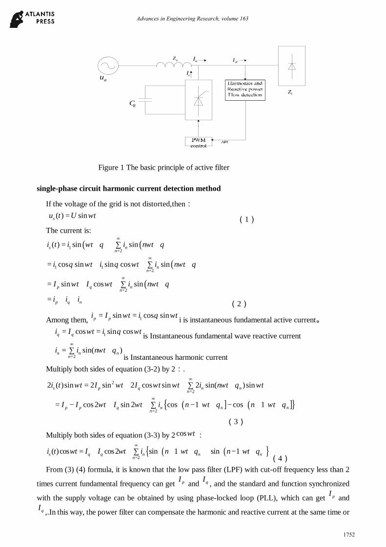
The basic principle of active power filter The active filter consists of two main parts: harmonic and reactive power detection circuits and
compensation circuits that produce compensation current. The former's role is to detect harmonic and reactive current components from the compensation objects. The latter's role is to generate equal amplitude and phase harmonic components based on the detected harmonic and reactive currents, and then injects the power grid to achieve the purpose of real-time harmonic compensation. The basic principle structure of the voltage type parallel type is shown in Figure 1..
7th International Conference on Energy, Environment and Sustainable Development (ICEESD 2018)
Copyright © 2018, the Authors. Published by Atlantis Press. This is an open access article under the CC BY-NC license (http://creativecommons.org/licenses/by-nc/4.0/).
Advances in Engineering Research, volume 163
1751
au
dC
aZ
cI
aI alI
lZ
Figure 1 The basic principle of active filter
single-phase circuit harmonic current detection method
If the voltage of the grid is not distorted,then:
( ) sinsu t U tω= (1) The current is:
( ) ( )
( )
( )
12
1 12
2
( ) sin sin
cos sin sin cos sin
sin cos sin
s nn
nn
p q nn
p q n
i t i t i n t
i t i t i n t
I t I t i n t
i i i
ω θ ω θ
θ ω θ ω ω θ
ω ω ω θ
∞
=
∞
=
∞
=
= + + ∑ +
= + + ∑ +
= + + ∑ +
= + + (2)
Among them, 1sin cos sinp pi I t i tω θ ω= = i is instantaneous fundamental active current。
1cos sin cosq qi I t i tω θ ω= = is Instantaneous fundamental wave reactive current
2sin( )n n n
ni i n tω θ
∞
== ∑ +
is Instantaneous harmonic current Multiply both sides of equation (3-2) by 2:.
2
22 ( )sin 2 sin 2 cos sin 2 sin( )sins p q n n
ni t t I t I t t i n t tω ω ω ω ω θ ω
∞
== + + ∑ +
( ) ] ( ) ]
2cos 2 sin 2 cos 1 cos 1p p q n n n
nI I t I t i n t n tω ω ω θ ω θ
∞
== − + + ∑ − + − + +
(3)
Multiply both sides of equation (3-3) by 2 cos tω :
( ) ( ) 2
( )cos cos2 sin 1 sin 1s q q n n nn
i t t I I t i n t n tω ω ω θ ω θ∞
== + + ∑ + + + − + (4)
From (3) (4) formula, it is known that the low pass filter (LPF) with cut-off frequency less than 2
times current fundamental frequency can get pI and qI , and the standard and function synchronized
with the supply voltage can be obtained by using phase-locked loop (PLL), which can get pI and qI ,.In this way, the power filter can compensate the harmonic and reactive current at the same time or
Advances in Engineering Research, volume 163
1752
only harmonics according to the user's choice. If the harmonic and reactive current are compensated at the same time, it only needs to separate the active current of the fundamental wave as the compensation current, then the algorithm is simpler.
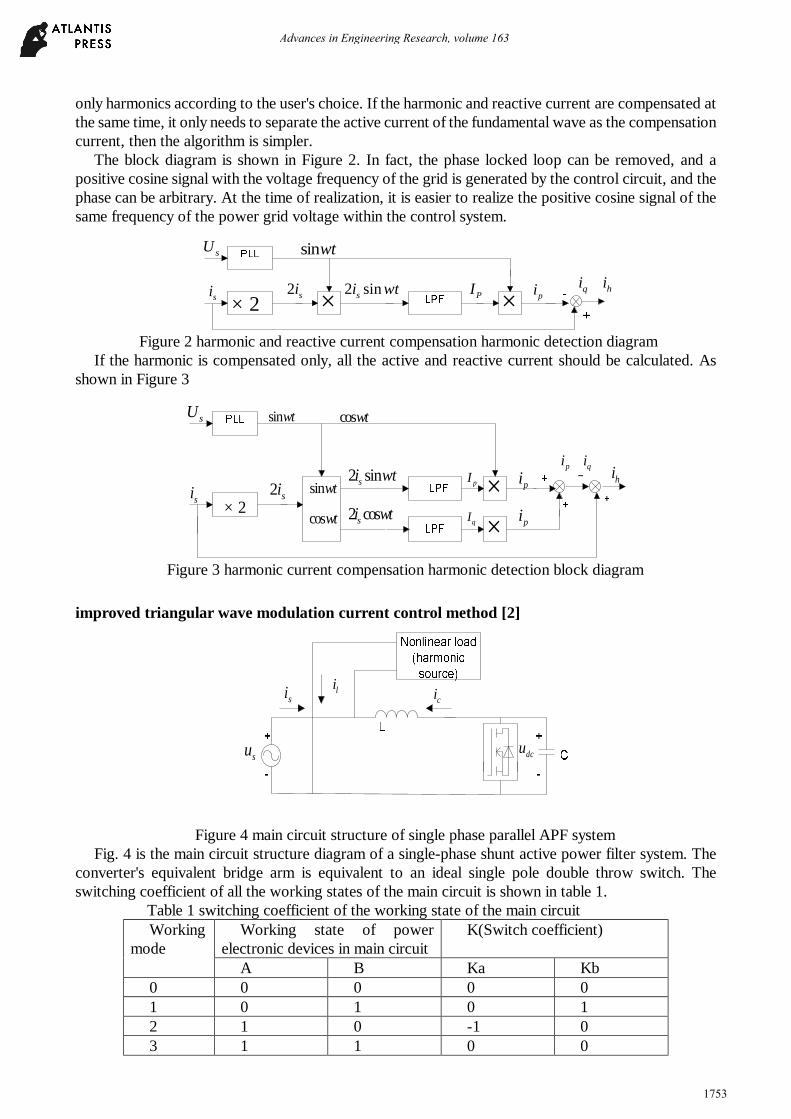
The block diagram is shown in Figure 2. In fact, the phase locked loop can be removed, and a positive cosine signal with the voltage frequency of the grid is generated by the control circuit, and the phase can be arbitrary. At the time of realization, it is easier to realize the positive cosine signal of the same frequency of the power grid voltage within the control system.
××2×q hi i+
PI2 sinsi tω pi2 si
sU
si
sin tω
Figure 2 harmonic and reactive current compensation harmonic detection diagram
If the harmonic is compensated only, all the active and reactive current should be calculated. As shown in Figure 3
×2×
p qi i+pi2 si
sU
si
sin tω cos tω
sin tω
cos tω 2 cossi tω
2 sinsi tω
× pi
− hipI
qI
Figure 3 harmonic current compensation harmonic detection block diagram
improved triangular wave modulation current control method [2]
su
si cili
dcu
Figure 4 main circuit structure of single phase parallel APF system
Fig. 4 is the main circuit structure diagram of a single-phase shunt active power filter system. The converter's equivalent bridge arm is equivalent to an ideal single pole double throw switch. The switching coefficient of all the working states of the main circuit is shown in table 1.
Table 1 switching coefficient of the working state of the main circuit Working
mode Working state of power
electronic devices in main circuit K(Switch coefficient)
A B Ka Kb 0 0 0 0 0 1 0 1 0 1 2 1 0 -1 0 3 1 1 0 0
Advances in Engineering Research, volume 163
1753
The compensation current of the active power filter is generated by the interaction between the
output voltage dcku of the converter and su the voltage of the AC side on the filter inductance L.
[ ]*
*
1
1
ca dc s
t
cc s
t
di k u ud Ldi u ud L
= − = − (5)
In the formula, is the instruction current of the converter and the is the command voltage on the corresponding converter. From the upper form
** cc s
t
diu L ud
= + (6)
It can be seen that is related to the instantaneous voltage of the power supply, and there is a
linear proportional relationship between them. So a parameter which is directly proportional to the instantaneous value of the supply voltage is introduced. Then the control relation is shown in the form (7).
( )*1 2c c c su k i i k u= − +
(7)
Among them, 、 is the ratio coefficient, which can be realized through the PI controller and select the appropriate parameters.
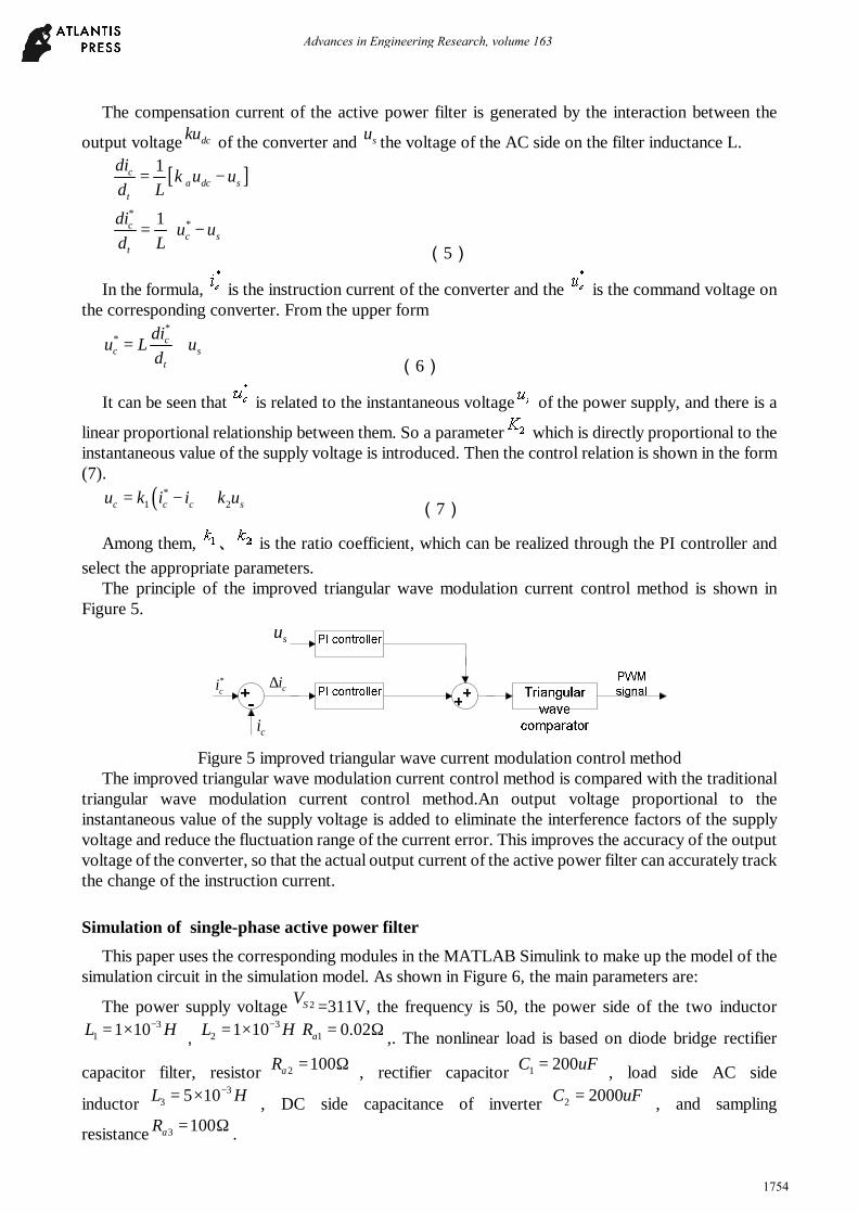
The principle of the improved triangular wave modulation current control method is shown in Figure 5.
ci∗
ci
su
ci∆
Figure 5 improved triangular wave current modulation control method
The improved triangular wave modulation current control method is compared with the traditional triangular wave modulation current control method.An output voltage proportional to the instantaneous value of the supply voltage is added to eliminate the interference factors of the supply voltage and reduce the fluctuation range of the current error. This improves the accuracy of the output voltage of the converter, so that the actual output current of the active power filter can accurately track the change of the instruction current.
Simulation of single-phase active power filter This paper uses the corresponding modules in the MATLAB Simulink to make up the model of the
simulation circuit in the simulation model. As shown in Figure 6, the main parameters are:
The power supply voltage 2SV =311V, the frequency is 50, the power side of the two inductor 3
1 1 10L H−= × ,3
2 1 10L H−= × 1 0.02aR = Ω ,. The nonlinear load is based on diode bridge rectifier
capacitor filter, resistor 2 100aR = Ω , rectifier capacitor 1 200C uF= , load side AC side
inductor3
3 5 10L H−= × , DC side capacitance of inverter 2 2000C uF= , and sampling
resistance 3 100aR = Ω .
Advances in Engineering Research, volume 163
1754

Simulation curve of single-phase active power filter The detected harmonic, reactive current, and compensatory power side current waveform are
shown in Figure 7-9.
Continuous
powergui
u(1)/20 com5
f(u)
com4
f(u)
com3
f(u)
com1
VS2v +-
VM 3
v+ -
VM2
v+ -
VM1
1
0.00001s+1
Transfer Fcn1
1
0.1s+1
Transfer Fcn
Step1
Sine Wave
Scope8 Scope7Scope6Scope5
Scope4
Scope3Scope2 Scope1
Saturation
RepeatingSequence
Ra3
Ra2
Ra1
A
B
+
-
PWM IGBT Inverter2
g
A
B
+
-
PWM IGBT Inverter1
Mux
Mux6
Mux
Mux4
Mux
Mux3
M ux
Mux2
Mux
Mux12
Mux Mux11
Mux
Mux1
M emory3
M emory1
NOTLogi1
AND Log6ANDLog5AND Log4ANDLog3
NOT Log2
L3
L2
L1
-1*u(1)Fcn-m21-u6
u(1)*u(2)
Fcn-m21-u3
u(1)-u(2)
Fcn-m 21-u2
u(2)-u(1)
Fcn-m21-u1
u(1)/80
DV
i+ -
CM4
i+ -
CM3
i+ -
CM2
i+
-
CM1
C2
C1
1000
5.1VDC
V12
Figure 6The simulation model of active filter
Figure 7 harmonic and reactive current d
figure 8 DC side voltage of converter
Figure 9 power side current after compensation
Figure 5-2 system simulation waveform after introducing APF
Advances in Engineering Research, volume 163
1755

From Fig. 8, it is known that the DC side voltage of the converter reaches 400V at the time of (about 0.1s), and the subsequent waveform is relatively straight, indicating that the control method of the voltage loop has basically succeeded in the control of the DC side voltage.When the DC side voltage does not reach the given value, the converter works in the inverter state. Voltage tracking control makes the compensation current track the harmonic and reactive current quickly, and has smaller tracking error. The width of the hysteresis loop in the model parameter is set to 1.
After the DC side voltage of the inverter reaches a specified value, the power supply side current is basically sinusoidal, and is in the same phase with the supply voltage. It shows that the single-phase active power filter basically realizes the function of eliminating harmonic and improving power factor.
Conclusions The detection of harmonic and reactive current and the tracking control of compensation current are
the two core parts of APF. In this paper, the harmonic and reactive current detection of single phase APF and the tracking control of compensation current are analyzed and verified by simulation.The detection method of single-phase harmonic current and the improved triangular wave modulation current control method is proposed.
It can track the variation of harmonic currents in real time, effectively suppress the harmonics, and successfully control the DC side voltage, so that APF can achieve the purpose of eliminating harmonic and improving power factor.
References:
[1] AREDES M,HAFNER J,HEUMANN K.Three-phase four-wire shunt active filter control strategies[J].IEEE Trans on Power Electronics,1997,12(2):311-318.,
[2] Ahmed Faheem Zobaa, Optimal multiobjective design of hybrid active power filters considering a distorted environment, IEEE Trans. Ind. Electron. 61 (1)(2014) 107–114.
[3]F.Z.Peng,H.Akagi,and A.Nabae,“ A new approsch to harmonic comensation in power system-A
combined system of shunt passive active filter” ,IEEE Trans.Ind,Appl,vol.26,no.6pp.983-990,1990
Advances in Engineering Research, volume 163
1756