Embed Size (px)
Citation preview

919Sensors and Materials, Vol. 33, No. 3 (2021) 919–932MYU Tokyo
S & M 2505
*Corresponding author: e-mail: [email protected]://doi.org/10.18494/SAM.2021.3207
ISSN 0914-4935 © MYU K.K.https://myukk.org/
Research and Development of Testing Device for Evaluating Force Transmission, Friction, and Contact
Pressure Distribution of Surgical Spring Forceps (Tweezers)
Rui Zhu,1* Yuma Takamura,1 Ikuo Yamamoto,2 Keitaro Matsumoto,1 and Takeshi Nagayasu1
1Department of Surgical Oncology, Nagasaki University Hospital, 1-7-1 Sakamoto, Nagasaki 852-8501, Japan2Engineering Department, Nagasaki University, 1-14 Bunkyo, Nagasaki 852-8521, Japan
(Received December 1, 2020; accepted February 16, 2021)
Keywords: spring forceps, force transmission, friction, contact pressure, load-cell sensor
To meet a surgeon’s need to compare the physical properties of conventional surgical spring forceps (tweezers), a hydraulic-driven system (HDS) based on syringes and syringe pumps is used for driving a left–right symmetrical lever linkage system of a testing device. Furthermore, by using an Arduino microcontroller and four load cells, a simple real-time feedback control system was built to digitally control the operating tweezers in the bar parts and monitor the forces on the jaw side of a surgical tweezers. Then, the same models of surgical tweezers from two different manufacturers were tested with the following test items: (1) the transmission relationship between the input side (bar area) and the output side (jaw side), (2) the contact pressure between the input side and the output side (tested using a Fujifilm Prescale System), (3) the horizontal friction on the jaw side, (4) the horizontal friction in the pinch bar area, and (5) the vertical friction in the pinch bar area. Finally, by analyzing the test results, the performances of the two surgical tweezers were compared and evaluated.
1. Introduction
Spring forceps have been used in a wide range of applications in human life over many years. They are made of wood, metal, or plastic and are of great use in the areas of food, clothing, housing, and transport, improving working conditions and significantly increasing the efficiency of human work. The reason for their widespread use is that the mechanism is very similar to how the human body uses the thumb and index finger to squeeze objects together, and they are also manipulated by using the thumb and index finger to perform their squeezing action. Also, in contrast to chopsticks, tweezer-like devices are based on a riveted or linked fixation at the end, which makes them simple to operate without the need for training, making them universally and widely used around the world. Nowadays, “forceps” is applied loosely to any surgical instrument that fixes or grips tissues or structures, embracing a definition that includes tweezers, dissecting forceps, intestinal clamps, artery forceps, dental forceps, bone cutting forceps, obstetric extraction forceps, and so on.(1)

920 Sensors and Materials, Vol. 33, No. 3 (2021)
Although the essential operation of forceps is easy to learn and medical device manufacturers have made considerable effort to optimize their performance, recent developments in bionics have led to the development of more effective nonslip structures based on traditional surgical forceps. However, for surgical procedures that require fine control of the force of the jaws in clinical situations, such as operations that must not damage the clamping target (e.g., membrane structures and blood vessels) and remain stable without slippage, practice and familiarity with the instrument are still the only way to improve the surgeon’s proficiency. At the same time, because of the rigorous environment in which surgical instruments are used and the simplicity of forceps construction, they are not used with the same variety of datasheet as electronic components and are operated purely by experience and feel. The same problem occurs in minimally invasive surgery,(2–5) which has become increasingly sophisticated in the last decade and is hampered by the complete loss of tactile feedback in robot-assisted surgery.(6,7) The loss and blurring of haptic feedback in these two types of surgery have therefore attracted the attention of many researchers and development organizations, who have attempted to provide assistance to surgeons using a variety of components such as haptic sensors,(8–11) optical sensors,(12,13) and posture sensors(14) in conjunction with real-time image assistance systems, augmented reality, virtual reality, and other technologies.(15–17) On the other hand, although new technologies, such as virtual reality, are used to varying degrees in clinical education, the practice and use of traditional surgical instruments have not been further enhanced with the introduction of new technologies. Therefore, at the request of surgeons and in response to the confusion surrounding the application of tweezers in clinical surgery, we have designed and developed a testing device based on the mechanics of tweezers to evaluate the mechanical properties of tweezers, focusing on the efficiency of force transmission, the contact pressure between the jaws and the pinch point, and the friction between the jaws and the pinch point. The aim is to provide surgeons and those in related fields with a relatively brief reference on the mechanical properties of existing tweezers as an option for future evaluation of the mechanical properties of new tweezer-like devices.
2. Materials and Methods
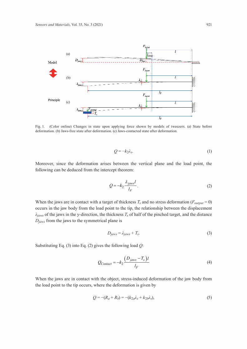
Owing to the left–right symmetry of tweezers, we can separate them by their symmetrical surfaces when discussing their principle of operation. Taking the right half as an example and fixing the trailing parting plane, the state before deformation of the tweezers due to the force applied is shown in Fig. 1(a). The states after deformation of the tweezers due to the forces exerted on them can be reduced to the suspension bridge problems in Figs. 1(b) (jaws-free state) and 1(c) (jaws-contacted state), where one end is fixed in the vertical plane, and the other end is free. A load Q (Finput) is applied to the bridge, l is the distance from the vertical plane to the point where the load acts, lF is the distance from the vertical plane to the tip, lCOG is the distance from the center of gravity (COG) to the load position, λs is the displacement of the load point in the y-direction, and λjaws is the displacement of the head end of the bridge in the y-direction. By Hooke’s law, the relationship between the load Q and the distance l from the vertical plane to the point of load action is
Sensors and Materials, Vol. 33, No. 3 (2021) 921
Q = −k2λs. (1)
Moreover, since the deformation arises between the vertical plane and the load point, the following can be deduced from the intercept theorem:
2jaws
F
lQ k
lλ
= − . (2)
When the jaws are in contact with a target of thickness Ts and no stress deformation (Foutput = 0) occurs in the jaw body from the load point to the tip, the relationship between the displacement λjaws of the jaws in the y-direction, the thickness Ts of half of the pinched target, and the distance Djaws from the jaws to the symmetrical plane is
Djaws = λjaws + Ts. (3)
Substituting Eq. (3) into Eq. (2) gives the following load Q:
( )
2jaws s
ContactF
D T lQ k
l
−= − (4)
When the jaws are in contact with the object, stress-induced deformation of the jaw body from the load point to the tip occurs, where the deformation is given by
Q = −(Ra + Rb) = −(k2aλs + k2bλs), (5)
Fig. 1. (Color online) Changes in state upon applying force shown by models of tweezers. (a) State before deformation. (b) Jaws-free state after deformation. (c) Jaws-contacted state after deformation.
(a)
(b)
(c)

922 Sensors and Materials, Vol. 33, No. 3 (2021)
where Ra is the reverse force at the fixed end of the vertical plane and Rb is the reverse force at the tip of the clamp with the target as a fulcrum. In this case, λs > λContact. Thus, we can classify the physical state of the tweezers in terms of the contact between the jaws of the tweezers and the pinching target as follows.
Free state—where a force is applied to the tweezers, and the force produces a deformation Q = Ra ≥ 0, but the jaws are not in contact with the target.Critical state—where a force applied to the tweezers produces a deformation Q = Ra ≥ 0, and the jaws are in contact with the target but there is no interaction force (Rb = 0). Then,
λjaws = Djaws − Ts. (6)
Force state—where the jaws come into contact with the target and generate an interaction force Q = Ra + Rb. Then,
( )jaws s
sF
D T ll
λ−
> . (7)
After discussions with several surgeons, we examined the tweezer holding position, with the middle finger and vice as support points between which the COG of the tweezers is positioned, and the thumb and index finger parallel to each other and holding the left and right branches of the tweezers, respectively. The clamping position, i.e., the load point, is between the jaws and the COG, usually about 10 to 20 mm from the COG.
2.1 Mechanical parts design
After a thorough analysis of the tweezer mechanism and how it is used, we designed and developed the test device, as shown in Fig. 2. By using a hydraulic-driven system (HDS) consisting of a pair of syringes and a syringe propulsion pump, the propulsion rods of the driven syringes drive two connected left–right symmetrical lever-rod actuators to control the input load at the pinching end of the tweezers. As shown in Fig. 2(a), to simulate the two-point support when the tweezers are held manually in the gripping position, two support platforms are provided to guide the tweezers on the central axis of the device, and the rear support platforms are grooved at the central axis to hold the tweezers in place so that they do not shift vertically on the central axis. The platforms with the two mounted load cells then form a worm actuation system through worm shafts positioned in them and the left and right levers with horizontal straight teeth. The contact position of the load cells with the tweezers is adjusted by rotating the worm to simulate the two-point pinching action for manual use of the tweezers. Furthermore, to maintain symmetry in the movement of the two sets of lever-connecting rods, the shafts holding the syringe pusher and the two connecting rods are extended, with the ends fixed in slides in aluminum frame slots parallel to the central axis. At this point, the basic mechanical structure of the tweezer operating system (TOS) is complete.
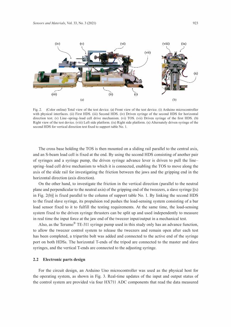
Sensors and Materials, Vol. 33, No. 3 (2021) 923
The cross base holding the TOS is then mounted on a sliding rail parallel to the central axis, and an S-beam load cell is fixed at the end. By using the second HDS consisting of another pair of syringes and a syringe pump, the driven syringe advance lever is driven to pull the line–spring–load cell drive mechanism to which it is connected, enabling the TOS to move along the axis of the slide rail for investigating the friction between the jaws and the gripping end in the horizontal direction (axis direction). On the other hand, to investigate the friction in the vertical direction (parallel to the neutral plane and perpendicular to the neutral axis) of the gripping end of the tweezers, a slave syringe [(x) in Fig. 2(b)] is fixed parallel to the column of support table No. 1. By linking the second HDS to the fixed slave syringe, its propulsion rod pushes the load-sensing system consisting of a bar load sensor fixed to it to fulfill the testing requirements. At the same time, the load-sensing system fixed to the driven syringe thrusters can be split up and used independently to measure in real time the input force at the jaw end of the tweezer input/output in a mechanical test. Also, as the Terumo® TE-311 syringe pump used in this study only has an advance function, to allow the tweezer control system to release the tweezers and remain open after each test has been completed, a tripartite bolt was added and connected to the active end of the syringe port on both HDSs. The horizontal T-ends of the tripod are connected to the master and slave syringes, and the vertical T-ends are connected to the adjusting syringe.
2.2 Electronic parts design
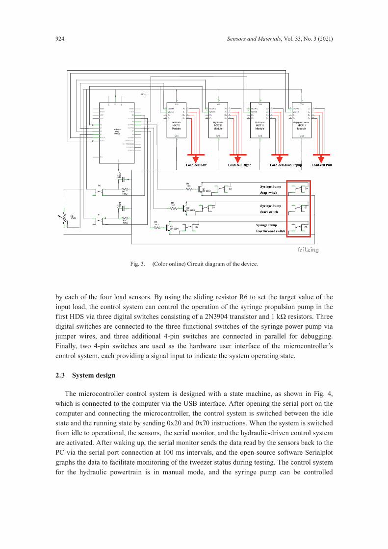
For the circuit design, an Arduino Uno microcontroller was used as the physical host for the operating system, as shown in Fig. 3. Real-time updates of the input and output status of the control system are provided via four HX711 ADC components that read the data measured
Fig. 2. (Color online) Total view of the test device. (a) Front view of the test device. (i) Arduino microcontroller with physical interfaces. (ii) First HDS. (iii) Second HDS. (iv) Driven syringe of the second HDS for horizontal direction test. (v) Line–spring–load cell drive mechanism. (vi) TOS. (vii) Driven syringe of the first HDS. (b) Right view of the test device. (viii) Left side platform. (ix) Right side platform. (x) Alternately driven syringe of the second HDS for vertical direction test fixed to support table No. 1.
(a) (b)
924 Sensors and Materials, Vol. 33, No. 3 (2021)
by each of the four load sensors. By using the sliding resistor R6 to set the target value of the input load, the control system can control the operation of the syringe propulsion pump in the first HDS via three digital switches consisting of a 2N3904 transistor and 1 kΩ resistors. Three digital switches are connected to the three functional switches of the syringe power pump via jumper wires, and three additional 4-pin switches are connected in parallel for debugging. Finally, two 4-pin switches are used as the hardware user interface of the microcontroller’s control system, each providing a signal input to indicate the system operating state.
2.3 System design
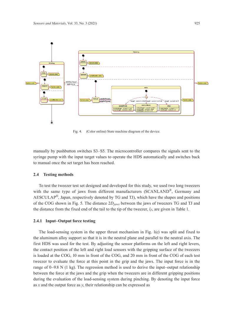
The microcontroller control system is designed with a state machine, as shown in Fig. 4, which is connected to the computer via the USB interface. After opening the serial port on the computer and connecting the microcontroller, the control system is switched between the idle state and the running state by sending 0x20 and 0x70 instructions. When the system is switched from idle to operational, the sensors, the serial monitor, and the hydraulic-driven control system are activated. After waking up, the serial monitor sends the data read by the sensors back to the PC via the serial port connection at 100 ms intervals, and the open-source software Serialplot graphs the data to facilitate monitoring of the tweezer status during testing. The control system for the hydraulic powertrain is in manual mode, and the syringe pump can be controlled
Fig. 3. (Color online) Circuit diagram of the device.
Sensors and Materials, Vol. 33, No. 3 (2021) 925
manually by pushbutton switches S3–S5. The microcontroller compares the signals sent to the syringe pump with the input target values to operate the HDS automatically and switches back to manual once the set target has been reached.
2.4 Testing methods
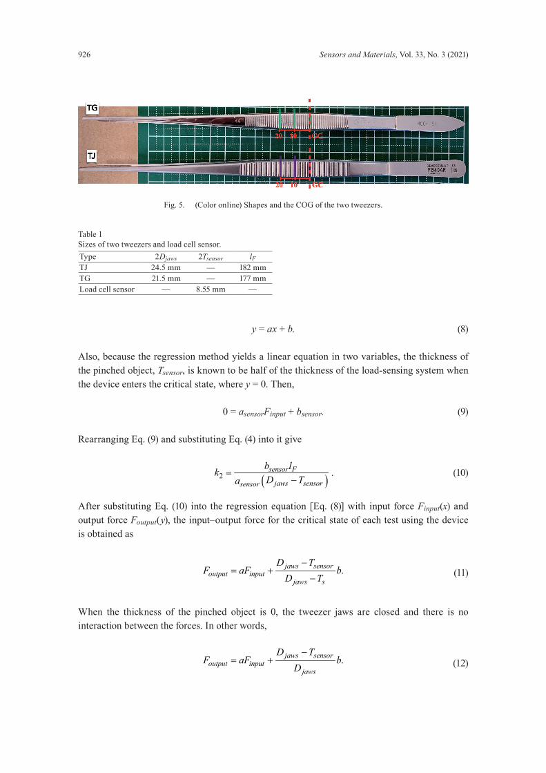
To test the tweezer test set designed and developed for this study, we used two long tweezers with the same type of jaws from different manufacturers (SCANLAND®, Germany and AESCULAP®, Japan, respectively denoted by TG and TJ), which have the shapes and positions of the COG shown in Fig. 5. The distance 2Djaws between the jaws of tweezers TG and TJ and the distance from the fixed end of the tail to the tip of the tweezer, lF, are given in Table 1.
2.4.1 Input–Output force testing
The load-sensing system in the upper thrust mechanism in Fig. 1(c) was split and fixed to the aluminum alloy support so that it is in the neutral plane and parallel to the neutral axis. The first HDS was used for the test. By adjusting the sensor platforms on the left and right levers, the contact position of the left and right load sensors with the gripping surface of the tweezers is loaded at the COG, 10 mm in front of the COG, and 20 mm in front of the COG of each test tweezer to evaluate the force at this point in the grip and the jaws. The input force is in the range of 0–9.8 N (1 kg). The regression method is used to derive the input–output relationship between the force at the jaws and the grip when the tweezers are in different gripping positions during the evaluation of the load-sensing system during pinching. By denoting the input force as x and the output force as y, their relationship can be expressed as
Fig. 4. (Color online) State machine diagram of the device.
926 Sensors and Materials, Vol. 33, No. 3 (2021)
y = ax + b. (8)
Also, because the regression method yields a linear equation in two variables, the thickness of the pinched object, Tsensor, is known to be half of the thickness of the load-sensing system when the device enters the critical state, where y = 0. Then,
0 = asensorFinput + bsensor. (9)
Rearranging Eq. (9) and substituting Eq. (4) into it give
( )2sensor F
jaws sensorsensor
b lkD Ta
=−
. (10)
After substituting Eq. (10) into the regression equation [Eq. (8)] with input force Finput(x) and output force Foutput(y), the input–output force for the critical state of each test using the device is obtained as
.jaws sensoroutput input
jaws s
D TF aF b
D T−
= +− (11)
When the thickness of the pinched object is 0, the tweezer jaws are closed and there is no interaction between the forces. In other words,
.jaws sensoroutput input
jaws
D TF aF b
D−
= + (12)
Fig. 5. (Color online) Shapes and the COG of the two tweezers.
Table 1Sizes of two tweezers and load cell sensor.Type 2Djaws 2Tsensor lFTJ 24.5 mm — 182 mmTG 21.5 mm — 177 mmLoad cell sensor — 8.55 mm —
Sensors and Materials, Vol. 33, No. 3 (2021) 927
To follow the clinical scenario as closely as possible, a layer of foam of approximately 1 mm thickness was added to the contact between the left and right load sensors and the tweezer gripping surfaces, and the finger portion of a surgical glove was applied.
2.4.2 Contact pressure
The Fujifilm Prescale System (FPS) was used in this study to measure the contact pressure distribution between the jaws and the gripping surface for contact pressure testing. The LLLW film used has a pressure test range of 0.6–2.5 MPa. When the jaws close and generate a pressure greater than 0.6 MPa with an input load greater than 3.92 N (400 gf), the range of input forces in the contact pressure test is 3.92 N (400 gf) to 9.8 N (1000 gf) and the input load is set 10 mm in front of the COG of the tweezers. Because of the left–right symmetry of the tweezers, the measurement film is set at the jaws and the right-side gripping surface. After 120 s of static testing under the target input force conditions, the film’s stained portion revealed the pressure distribution on a single side surface. After the test, the contact pressure distribution corresponding to the target input load was obtained by reading the stain information on the film using a scanner and FPS software.
2.4.3 Horizontal friction on jaws
A plastic sheet of approximately 0.5 mm thickness was fixed between two aluminum alloy frames, and the frames were fixed to the table using a bench vice, which was used to adjust the plastic sheet so that it is in the same plane as the central axis of the test device. Once the drive unit pinches the tweezers to reach the input load target, the second HDS is used to pull the TOS, generating a relative movement between the jaws and the plastic sheeting. For this test, the input load position was set 20 mm in front of the tweezer COG, the input force targets were 3.92, 4.9, 5.88, 7.84, and 9.8 N, and each target was tested five times. The pulling force during the change from static to dynamic friction was extracted as a result, and the median value of the results was taken. The relationship between the jaw friction force and the input force at the gripping end of the tweezers was obtained using the regression method.
2.4.4 Horizontal friction on bars
By placing the tweezers reversely and securing the tail, the TOS is used to pinch the tweezers against the input target force. The second HDS is then used to pull the TOS to generate relative motion between the left and right load sensors and the gripping surface of the tweezers. The input target forces for this test were 0.98 and 1.96 N. The input load position was set 20 mm in front of the tweezer COG. Each target was tested five times. The pulling force during the change from static to dynamic friction was evaluated as the result, and the median value of the results was taken. The relationship between the horizontal friction force and the end input force on the gripping surface of the tweezers in the horizontal direction was obtained using the regression method.
928 Sensors and Materials, Vol. 33, No. 3 (2021)
2.4.5 Vertical friction on bars
Referring to Fig. 1(c), the second HDS is used to connect the syringe fixed to support stand No. 1. The tweezers are placed in the normal orientation and the TOS is used to pinch the tweezers. After a target force is set, the syringe is driven to push the tweezers upwards to create relative motion between the left and right load sensors and the tweezer gripping surface. The input target forces for this test were 1.96 and 2.94 N. The input load position was set at 20 mm in front of the tweezer COG. Each target was tested five times. The pulling forces during the change from static to dynamic friction were extracted as a result and the median value of the results was taken.
3. Results
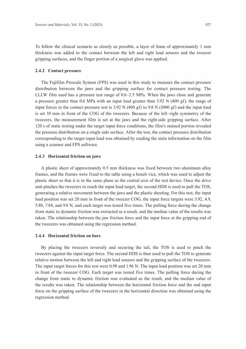
3.1 Force transmission
The results obtained by the load-sensing system are shown in Fig. 6.
3.2 Contact pressure distribution
Devices TG and TJ are subjected to forces in the range of 3.92 to 9.8 N during each test, and the contact pressure distribution results are shown in Figs. 7(a) and 7(b). The resolution of the figures is 0.125 mm2 per pixel. Moreover, Fig. 7(c) shows the comparison of total distribution area for TG and TJ.
Fig. 6. (Color online) Force transmission. (a) TG. (b) TJ. (c) Comparison at the COG. (d) Comparison at 10 mm in front of the COG. (e) Comparison at 20 mm in front of the COG.
(a)
(b)
(c)
(d)
(e)

Sensors and Materials, Vol. 33, No. 3 (2021) 929
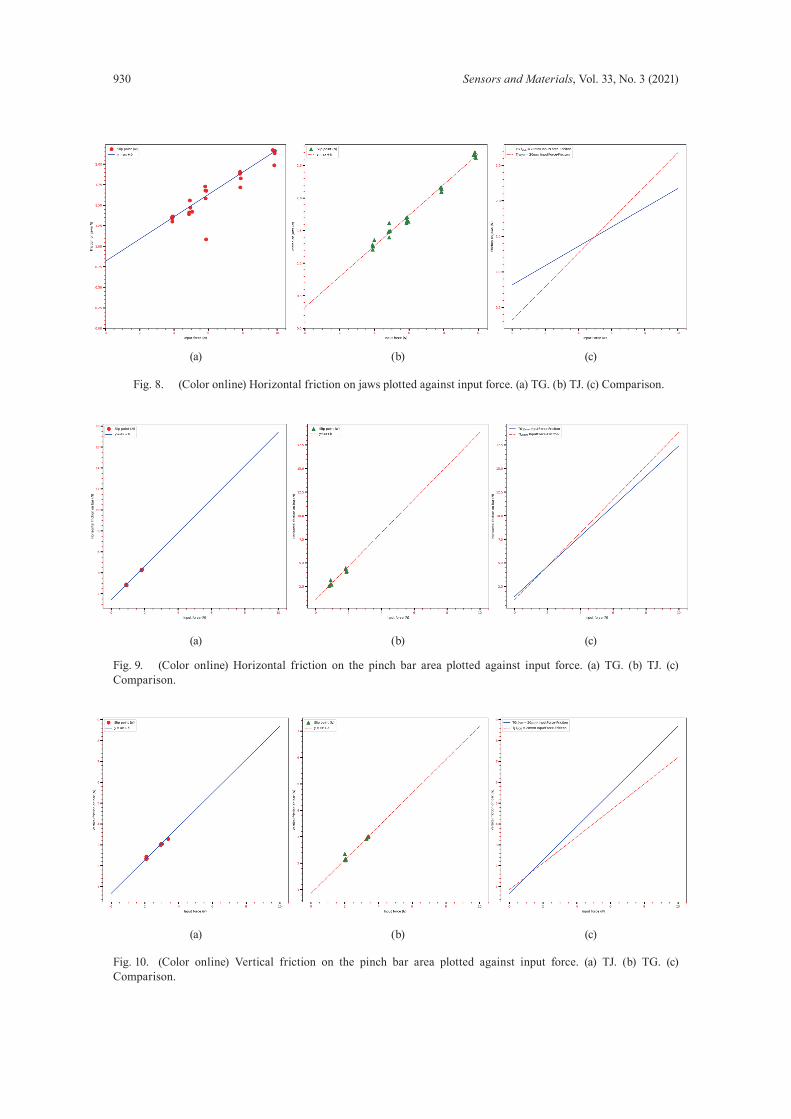
3.3 Horizontal friction on jaws
The results obtained in the jaw friction tests in the horizontal direction are shown in Fig. 8.
3.4 Horizontal friction on the pinch bar area
The results obtained in the holding bar friction tests in the horizontal direction are shown in Fig. 9.
3.5 Vertical friction on the pinch bar area
The results obtained in the holding bar friction tests in the vertical direction are shown in Fig. 10.
4. Discussion
By comparing the relationship between the grip input and the jaw output of tweezers TJ and TG, it can be concluded that for equal input loads, the farther the grip position is from the COG of the tweezers, the greater the jaw output force. This corresponds to a surgeon applying
Fig. 7. (Color online) Contact pressure distribution of jaws. (a) TJ. (b) TG. (i–vii) 3.92 to 9.8 N. (c) Comparison of total distribution area for TG and TJ.
(a) (b)
(c)
930 Sensors and Materials, Vol. 33, No. 3 (2021)
Fig. 8. (Color online) Horizontal friction on jaws plotted against input force. (a) TG. (b) TJ. (c) Comparison.
Fig. 9. (Color online) Horizontal friction on the pinch bar area plotted against input force. (a) TG. (b) TJ. (c) Comparison.
Fig. 10. (Color online) Vertical friction on the pinch bar area plotted against input force. (a) TJ. (b) TG. (c) Comparison.
(a) (b) (c)
(a) (b) (c)
(a) (b) (c)
Sensors and Materials, Vol. 33, No. 3 (2021) 931
tweezers in a clinical scenario. Furthermore, comparison of the force input–output relationships of TJ and TG at the same distance for the different COGs shows that TG is more responsive than TJ, as evidenced by the fact that when the output force y is 0, the input force x is smaller for TG and it can pinch the target more quickly than TJ. Furthermore, the difference in the slope a between the two tweezers is so small that in the input force range of 0–9.8 N, TG requires a smaller input force than TJ to achieve the same jaw output force. It can also be seen from Fig. 7(c) that TG has almost relatively more significant area of distribution than TJ for the same input. In terms of horizontal jaw friction, from Fig. 8, the input force–friction lines of TG and TJ intersect at 4.9 N. This means that objects pinched with TG are less likely to slip when the input force is less than 4.9 N. Also, because the slope of TJ is substantially greater than that of TG, TJ is substantially better than TG when a fixed pinch is required, and damage to the pinched target surface is less likely. The test data for both horizontal and vertical tweezer grips gave promising results, with TG showing better performance in the vertical direction and TJ showing better performance in the horizontal direction. By looking at the nonslip construction of the two types of tweezers in Fig. 5, it can be seen that the construction is almost identical, with a wavy concave–convex construction parallel to the gripping surface of the tweezers and perpendicular to the central axis. The differences between the tweezers are in the degree and density of the convexity. Approximating the convexity as a sinusoidal function, TG has a shorter period and lower amplitude. At the same time, neither tweezer exhibits much friction at the grip end at low forces of up to 3.92 N. This is because the friction of the two types of tweezers is low. In summary, TG is more effective than TJ at low input forces of up to 3.92 N. Furthermore, by comparing the results of the jaw friction test with those of the horizontal friction test of the grip end, the results for the test devices deviate significantly from the test data in the jaw friction test.
5. Conclusions
We have developed a testing device for tweezer-like instruments based on an Arduino microcontroller and load sensors using a lever-rod drive system with a hydraulic powertrain consisting of syringes and syringe pumps in combination with a slide, spring, and wire. The test device was developed to evaluate the strengths and weaknesses of the two types of tweezers and to validate the effectiveness of the test device by evaluating the input–output force and friction–input force characteristics, the contact pressure distribution at the gripping end of the jaws, and the input–friction force characteristic at the gripping end in both the horizontal and vertical directions. By comparing the data, the reasons for the large deviations in the grip-jaw friction–input force results of the test devices were identified. Also, the test data and evaluation results of the two types of tweezers can serve as a useful reference for surgeons and medical students to improve their proficiency in using these two types of tweezers. In the future, we expect that by using this device to evaluate the performance of more surgical forceps, it will provide an improved reference for relevant professionals to choose
932 Sensors and Materials, Vol. 33, No. 3 (2021)
appropriate instruments and to improve their proficiency with them more effectively. It is also expected that the mechanism of the device will serve as a reference for future robotic-assisted surgical devices.
Acknowledgments
Firstly, thanks go to the Department of Oncology, Nagasaki University Hospital, for providing materials such as syringes and syringe propellers for this study, and the surgeons for their detailed answers to various questions regarding the clinical application of forceps-like devices, which greatly assisted in the development and refinement of the test set. Thanks are also due to the Yamamoto Laboratory, Engineering Department, Nagasaki University, for providing the premises and various helpful instructions for the fabrication and testing of the test device.
References
1 J. Kirkup: Ann. R. Coll. Surg. Engl. 78 (1996) 544. http://www.ncbi.nlm.nih.gov/pmc/articles/pmc2502851 2 D. Vyas and S. Cronin: Am. J. Robot. Surg. 2 (2015) 39. https://doi.org/10.1166/ajrs.2015.1018 3 A. M. Okamura: Curr. Opin. Urol. 19 (2009) 102. https://doi.org/10.1097/MOU.0b013e32831a478c 4 T. Jaschinski, C. G. Mosch, and M. Eikermann: Cochrane Database Syst. Rev. 11 (2018) 1. https://doi.
org/10.1002/14651858.CD001546.pub4 5 N. Bandari, J. Dargahi, and M. packirisamy: IEEE Access 8 (2020) 7682. https://doi.org/10.1109/
ACCESS.2019.2962636 6 S. Schostek, M. O. Schurr, and G. F. Buess: Med. Eng. Phys. 31 (2009) 887. https://doi.org/10.1016/
j.medengphy.2009.06.003 7 J. Stoll and P. Dupont: Proc. 2006 IEEE Int. Conf. Robotics and Automation (Orlando, Florida, 2006) 4309–
4311. 8 A. Tobergte, and P. Helmer: Proc. 2011 IEEE/RSJ Int. Conf. Intelligent Robots and Systems (San Francisco,
CA, 2011) 3023–3030. https://doi.org/10.1109/IROS.2011.6094433 9 A. M. Okamura: Ind. Rob. 31 (2004) 499. https://doi.org/10.1108/01439910410566362 10 C. Pacchierotti, S. Scheggi, and D. Prattichizzo: Front. Robot. AI 3 (2016) 53. https://doi.org/10.3389/
frobt.2016.00053 11 F. Amirabdollahian, S. Livatino, and B. Vahedi: J. Robotic Surg. 12 (2018) 11. https://doi.org/10.1007/s11701-
017-0763-4 12 J. Peirs, J. Clijnen, and D. Reynaerts: Sens. Actuators, A 115 (2004) 447. https://doi.org/10.1016/j.sna.2004.04.057 13 P. Puangmali, H. Liu, and K. Althoefer: Proc. 2008 IEEE Inter. Conf. Robotics and Automation (Pasadena,
CA, 2008) 2934–2939. https://doi.org/10.1109/ROBOT.2008.4543655. 14 R. C. King, L. Atallah, and B. P. L. Lo: IEEE Trans. Inf. Technol. Biomed. 13 (2009) 673. https://doi.
org/10.1109/TITB.2009.2029614 15 C. Zheng, L. W. Lau, and J. Cha: Biomed. Opt. Express 9 (2018) 5962. https://doi.org/10.1364/BOE.9.005962 16 L. Chen, W. Tang, and N. W. John: Healthc. Technol. Lett. 4 (2017) 163. https://doi.org/10.1049/htl.2017.0068 17 S. M. Kannangara, E. Fernando, and N. D. Nanayakkara: Proc. 2016 6th IEEE Int. Conf. Biomedical Robotics
and Biomechatronics (IEEE, 2016) 396–400. https://doi.org/10.1109/BIOROB.2016.7523659