Embed Size (px)
Citation preview

1
RIGA TECHNICAL UNIVERSITY Faculty of Power and Electrical Engineering
Institute of Industrial Electronics and Electrical Engineering
Lauris BISENIEKS Doctoral student of program “Computer control of electrical technology”
Research and Development of Interface Converter for PMSG Based Wind Generator
Summary of doctoral thesis
Scientific supervisor Dr.sc.ing., Professor
Ilya GALKIN
Riga 2011

2
UDK 621.311.245(043.2) Bi 830 r
Bisenieks L. Research and development of interface converter for PMSG based wind generator. Summary of doctoral thesis.- Lauris Bisenieks, 2011.-49 lpp. Printed according to the decision of IEE institute on May 25th, 2011. Protocol Nr.56 This work has been supported by the European Social Fund within the project «Support for the implementation of doctoral studies at Riga Technical University».
ISBN 978-9984-49-345-9

3
DOCTORATE WORK PRESENTED TO OBTAIN THE DOCTOR'S DEGREE IN ENGINEERING SCIENCES
Doctorate work for the doctor's degree in the engineering sciences was publicly presented on the 02.08.2011 at 10:30 o’clock in Riga Technical University, Kalku str. 1 – 119
OFFICIAL OPPONENTS
Professor, Dr.hab.sc.ing. Ivars Rankis Riga Technical University, Latvia Professor, Dr.hab. Sc.Ing. Ryszard Strzelecki Gdynia Maritime University, Poland Senior Researcher, Dr.sc.ing. Leonards Latkovskis Institute of Physical Energetics, Latvia
CONFIRMATION
Hereby I confirm that I have worked out the present doctorate work, which is submitted for consideration to the Riga's Technical University for the degree of Doctor of engineering sciences. Doctorate work has not been submitted in any other university for obtaining the Doctor’s degree. Lauris Bisenieks ………………………. Date ………………………. The doctorate work is written in English language, contains: 108 pages, introduction, 3 chapters, conclusions, 88 figures, 74 formulas, 13 tables, 100 references and 2 appendixes.

4
SIGNIFICANCE OF THE TOPIC
Continuous growth of the earth population and improving standards of living are the main driving forces for the continuous growth of the energy demand. Although the energy use per unit of gross domestic product (GDP) is declining in most countries, the GDP increase is faster than efficiency growth, causing to use more and more recourses for energy production. It is forecasted that this trend will continue in the upcoming decades. Limited availability of fossil energy resources, such us coal, natural gas, oil and nuclear, urge to make use of renewable sources for electric energy generation. Moreover, the use of fossil fuels are connected with greenhouse gas emissions and in case of the nuclear energy, there is a high potential of radiation product leakage that can cause irreversible damage to environment, but used fuel and old utility disposal is connect with high expenses after the closure of nuclear power stations. Environmental aspects and expenses are additional driving forces for technology development of alternative energy usage. The cost of electrical energy from alternative energy sources is major concern that prohibits wider its utilization. This is particularly true for micro and small wind turbine applications due to the low typical installation height and as a result lower average wind speeds that leads to lower produced energy. Since there is no possibility to affect average wind speeds, the only way how to increase the energy output of wind turbine systems (WTS) is to improve the efficiency of all its components. This dissertation is devoted to new power electronics converter development for micro and small wind turbines.
OBJECTIVE OF THE WORK AND FULFILLED TASKS
The objective of this doctoral work is to research and develop of interfacing converter for PMSG based variable speed wind turbines. Since the whole interfacing converter is a complex system consisting of a power converter, control unit and other elements, several specific tasks are defined: • analysis and comparison of DC/DC converters with HF
isolation in context of PMSG based VSWT interfacing converter with quasi impedance source (qZS) converters for wind applications;
• analysis of wind theory and PMSG based variable speed wind turbine properties to define the requirements for interfacing converter;
5
• analysis of qZS DC/DC converters in context of VSWT applications;
• development of interfacing converter prototype for wind applications;
• analysis of experimental results and conclusions of system potential;
• development of new qZS DC/DC converter topology with improved boost properties.
METHODS AND MEANS OF RESEARCH
In order to estimate the proposed idea of new interface converter for PMSG based VSWT the number of simulations was performed in PSIM and Matlab Simulink. QZS DC/DC converters were simulated in PSIM, but behaviour of controlled rectifier was evaluated by Simulink. To verify the correct operation of proposed interface converter with multistage boost operation the experiments were carried out. Controlled rectifier was tested with PMSG at different speed and respective power levels, firstly. Then the tests with qZS DC/DC converter with HF isolation were carried out at corresponding voltage and power levels, to evaluate the predicted operation modes. Analytic analysis of qZS based DC/DC converter with improved boost properties was done. Analysis of proposed interface converters suitability for different VSWT applications was carried out.
SCIENTIFIC ORIGINALITY
A novel interface converter based on controlled rectifier with PFC functionality and qZS DC/DC converter with HF isolation has been elaborated and verified by means of simulations, analytic calculations and experiments; A novel simplified interface converter based on uncontrolled rectifier and qZS DC/DC converter with HF isolation has been elaborated and verified by means of simulations and experiments for micro wind turbines; A novel qZS DC/DC converter with switched inductors are proposed and analytic equations are given. Design of interface converter is described for further market ready product development; Comparison of proposed topologies of interface converter is made.

6
PRACTICAL APPLICATION OF THE WORK
The elaborated prototype of the interface converter can be further developed to commercial product and launched on the market for micro and small wind turbine systems. Typical application of such system can be considered as stand-alone and grid connected systems
WORK APPROBATION
The approbation of work has been realized by presenting the results of the research at the following international conferences: 1. Bisenieks L., Galkins I. Estimation of Converter Topologies for Small Wind Turbine // Topical Problems in the Field of Electrical and Power Engineering*Doctoral School of Energy and Geotechnology II : Proceedings, Estonia, Parnu, 14.-19. June, 2010. - pp 25-28. 2. Bisenieks L., Vinnikov D., Galkins I. New Isolated Converter for Interfacing PMSG Based Wind Turbine with Distribution Network // Topical Problems in the Field of Electrical and Power Engineering*Doctoral School of Energy and Geotechnology II: Proceedings, Estonia, Parnu, 10.-15. January, 2011. - pp 100-107. 3. Bisenieks L., Vinikkov D., Galkins I. New Isolated Interface Converter for Grid-Connected PMSG based Wind Turbines // Proceedings of 10th International Conference on Environment and Electrical Engineering, Italy, Rome, 8.-11. May, 2011. - pp 869-872. 4. Bisenieks L., Vinikkov D., Zaķis J. Analysis of Operating Modes of the Novel Isolated Interface Converter for PMSG Based Wind Turbines // Proceedings of the III International Conference on Power Engineering, Energy and Electrical Drives, Spain, Torremolinos, 11.-13. May, 2011. - pp 1-8. 5. Bisenieks L., Vinikkov D., Galkins I. New Converter for Interfacing PMSG based Small-Scale Wind Turbine with Residential Power Network // Proceedings of the 7th International Conference-Workshop Compatibility and Power Electronics, Estonia, Tallinna, 1.-3. June, 2011. - pp 354-359. 6. Husev O., Bisenieks L. Control Algorithm for Front-End Active Rectifier for Grid-Connected PMSG based Wind Turbines // Student Forum Proceedings of the 7th International Conference-Workshop Compatibility and Power Electronics CPE 2011, Estonia, Tallinn, 3.-3. June, 2011. - pp 82-86

7
7. Bisenieks, L.; Vinnikov, D.; Galkin, I. (2011). PMSG based residential wind turbines: possibilities and challenges. In: Agronomy research: Biosystems Engineering BSE2011. 2011, accepted for publication 8. Bisenieks, L.; Vinnikov, D.; Ott, S. (2011). Switched Inductor Quasi-Z-Source Based Back-to-Back Converter for Variable Speed Wind Turbines with PMSG. In: ELECTRONICS AND ELECTRICAL ENGINEERING: The 15th International Conference of ELECTRONICS, 2011, accepted for publication
AUTHOR’S PUBLICATIONS
1. Stepanovs A., Galkins I., Bisenieks L. Supercapacitor Usage in Uninterruptible Power Supply // Технiчна Електродинамiка, Ukraine, Alushta, 17.-21. September, 2006. - pp 45-48. 2. Bisenieks L., Galkins I. Simulation, validation and implementation of a control system for uninterruptible power suppl // ISBN 978-9985-69-041-3 Proceedings of the 4th International Symposium"Topical Problems of Education in the Field of Electrical and Power Engineering" , Estonia, Kuressaare, 15.-20. January, 2007. - pp 130-135. 3. Bisenieks L., Galkins I., Stepanovs A. Connection of Photovoltaic Modules to the Electricity Supply Grid or to a Local Consumer Utilizing Topology of the On-Line Converter // Conference Proceedings of the 11th International Conference on Solar Energy in High Latitudes, Latvia, Riga, 30.May-1. June, 2007. - pp 1-4. 4. Stepanovs A., Galkins I., Bisenieks L. Implementation of Supercapacitors in Uninterruptible Power Supplies // Proceedings of EPE 2007, Denmark, Alborg, 2.-5. September, 2007. - pp 1-7. 5. Stepanovs A., Galkins I., Bisenieks L. Pspice Simulation of an On-Line Converter Powered by a Photovoltaic Array // Технiчна електродинамiка, Ukraine, Alushta, 18.-22. September, 2007. - pp 79-82. 6. Bisenieks L., Stepanovs A., Galkins I. Comparison of a Traditional Diode Photovoltaic Model and Simplified I-V Curve Based Model // Proceedings of the 5th International Symposium "Topical Problems in the Field of Electrical and Power Engineering", Estonia, Kuresāre, 14.-19. January, 2008. - pp 73-77. 7. Stepanovs A., Bisenieks L., Galkins I. Comparison of Controllable Rectifiers for Direct-Current Supply System // Технічна електродинаміка. Тематичний випуск „Силова електроніка та енергоефективність”. - Київ, 2008. - Частина 2, с. 96-99. 8. Galkins I., Stepanovs A., Bisenieks L. Direct-Current Supply System with Capability of an Uninterruptible Power Supply // BEC 2008 :

8
2008 International Baltic Electronics Conference : Proceedings of the 11th Biennial Baltic Electronics Conference, Tallinn University of Technology, October 6-8, 2008, Tallinn, Estonia. - Piscataway, NJ : IEEE, 2008. - P. 301-304. 9. Stepanovs A., Galkins I., Bisenieks L., Sokolovs A. Development of a Modular Power Converter // Scientific Journal of RTU. 4. series., Power and Electrical Engineering. - 25. vol. (2009), pp 107-110. 10. Stepanovs A., Galkins I., Bisenieks L. Development of Fast and Easy Reconfigurable Modular Power Converter // Технiчна Електродинамiка, Ukraine, Alushta, 21.-26. September, 2009. - pp 17-20. 11. Bisenieks L., Vinogradov R., Lazdans A., Galkins I. Upgrade Possibilities of Low-Power Electric Scooter // Proceedings of the 51st Annual International Scientific Conference of Riga Technical University , Latvia, Riga, 11.-15. October, 2010. - pp 213-216. 12. Bisenieks L., Galkins I. Estimation of Step-up Converters for Photovoltaic // Topical Problems in the Field of Electrical and Power Engineering*Doctoral School of Energy and Geotechnology II" : Proceedings, Estonia, Parnu, 11.-16. January, 2010. - pp 227-231.

9
CONTENTS OF DOCTORAL THESIS
INTRODUCTION 1. CHALLENGES OF PMSG BASED WIND TURBINE 1.1. WIND ENERGY CONVERSION 1.1.1. Wind power conversion 1.1.2. Wind velocity distribution 1.2. WTS POWER CONFIGURATIONS 1.2.1. Interface converter topologies for PMSG based VSWT 1.3. RESIDENTIAL NETWORK 1.4. PMSG BASED WSVT CHARACTERISTICS 1.5. TOPOLOGY ANALYSIS OF INTERFACE CONVERTERS FOR WSVT 1.6. CONCLUSIONS 2. NEW ISOLATED CONVERTER TOPOLOGY 2.1. GENERATOR SIDE CONVERTER 2.1.1. Simulation results of generator side inverter 2.2. QZS BASED DC/DC CONVERTER WITH HF ISOLATION 2.2.1. Operating modes qZS based DC/DC converter 2.2.2. Discontinuous conduction mode of qZS inverter 2.2.3. Simulation and experimental results. 2.3. CONTROL METHODS 2.4. INTERFACE CONVERTER FOR MICRO TURBINES 2.5. CONCLUSIONS 3. QZS DC/DC CONVERTER WITH IMPROVED BOOST PROPERTIES 3.1. OPERATION MODES OF THE INTERFACE CONVERTER 3.2. ANALYSIS OF SIMULATION AND EXPERIMENTAL RESULTS 3.2.1. Analysis of experimental results of PWM rectifier 3.2.2. Analysis of simulation and experimental results of the SL qZSI 4. CONCLUSIONS AND FUTURE WORK REFERENCES

10
INTRODUCTION
Continuous growth of the earth population and improving standards of living are the main driving forces for the continuous growth of the energy demand. Although the energy use per unit of gross domestic product (GDP) is declining in most countries, the GDP increase is faster than efficiency growth, causing to use more and more recourses for energy production. Limited availability of fossil energy resources, such us coal, natural gas, oil and nuclear, urge to make use of renewable sources for electric energy generation. Moreover, the use of fossil fuels are connected with greenhouse gas emissions and in case of the nuclear energy, there is a high potential of radiation product leakage that can cause irreversible damage to environment, but used fuel and old utility disposal is connect with high expenses after the closure of nuclear power stations. Environmental aspects and expenses are additional driving forces for technology development of alternative energy usage. The cost of electrical energy from alternative energy sources is major concern that prohibits wider its utilization. This is particularly true for micro and small wind turbine applications due to the low typical installation height and as a result lower average wind speeds that leads to lower produced energy. Since there is no possibility to affect average wind speeds, the only way how to increase the energy output of wind turbine systems (WTS) is to improve the efficiency of all its components. This dissertation is devoted to new power electronics converter development for micro and small wind turbines. Wind energy is quite an attractive form of renewable energy especially at high latitudes where feasibility to apply direct solar energy conversion technologies is limited. The commercial potential of wind energy [72 TW] is five times higher than world energy demand in all forms [8]. However, the installed capacity in 2009 was only 159GW and there are the huge potential of grow [23]. Mechanical energy of wind turbines are converted in electrical energy with help of appropriate generators. Permanent magnet synchronous generators (PMSG) predominate in small turbines and become popular in large power range due to multipole design that eliminates the need for gearbox [19]. Although the energy yield is higher for large inland and off-shore installations, the issue of transmission and distribution losses still is of major concern. Distributed generation and smart grid technologies are introduced to reduce transmission losses by bringing closer energy generation and utilization and reducing load variations over time. The charging control of the
11
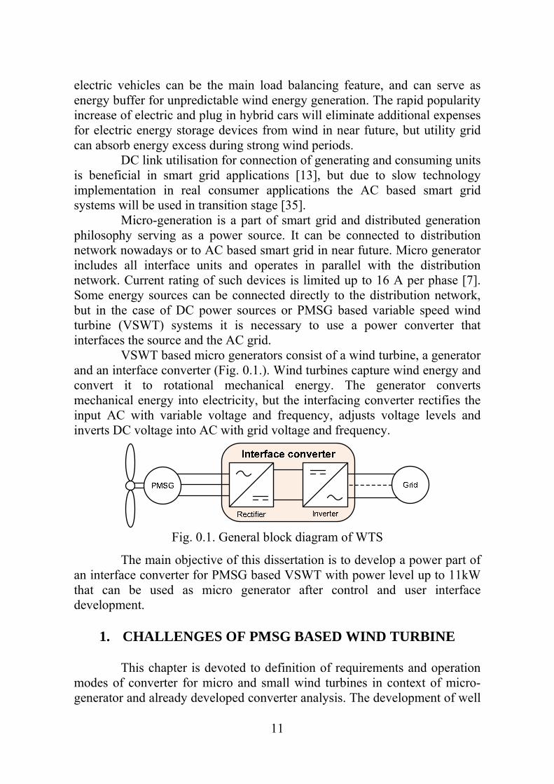
electric vehicles can be the main load balancing feature, and can serve as energy buffer for unpredictable wind energy generation. The rapid popularity increase of electric and plug in hybrid cars will eliminate additional expenses for electric energy storage devices from wind in near future, but utility grid can absorb energy excess during strong wind periods. DC link utilisation for connection of generating and consuming units is beneficial in smart grid applications [13], but due to slow technology implementation in real consumer applications the AC based smart grid systems will be used in transition stage [35]. Micro-generation is a part of smart grid and distributed generation philosophy serving as a power source. It can be connected to distribution network nowadays or to AC based smart grid in near future. Micro generator includes all interface units and operates in parallel with the distribution network. Current rating of such devices is limited up to 16 A per phase [7]. Some energy sources can be connected directly to the distribution network, but in the case of DC power sources or PMSG based variable speed wind turbine (VSWT) systems it is necessary to use a power converter that interfaces the source and the AC grid. VSWT based micro generators consist of a wind turbine, a generator and an interface converter (Fig. 0.1.). Wind turbines capture wind energy and convert it to rotational mechanical energy. The generator converts mechanical energy into electricity, but the interfacing converter rectifies the input AC with variable voltage and frequency, adjusts voltage levels and inverts DC voltage into AC with grid voltage and frequency.
Fig. 0.1. General block diagram of WTS
The main objective of this dissertation is to develop a power part of an interface converter for PMSG based VSWT with power level up to 11kW that can be used as micro generator after control and user interface development.
1. CHALLENGES OF PMSG BASED WIND TURBINE
This chapter is devoted to definition of requirements and operation modes of converter for micro and small wind turbines in context of micro-generator and already developed converter analysis. The development of well

12
suited converter for wind applications requires understanding of wind turbine generator system (WTGS) characteristics. Wind properties directly affect WTGS characteristics and for this reasons wind theory and wind regime is discussed. Since micro-generator can be connected to low voltage distribution or residential network, the main requirements and grid parameters are stated next. PMSG based WSVT characteristics and analysis of traditional grid tied converter topologies are given in the end of this chapter.
Wind energy conversion
Wind is a kind of air flow and, since this air has its own mass and speed, the wind contains some kinetic energy, which can be extracted. This energy is usually captured by an electromechanical generator which consists of wind turbine, some electrical generator and power electronic converter. Wind turbine transfers the energy from the air flow to the generator, where electrical energy is generated, but converter provides control of generator and turbine. the amount of mechanical power captured by the turbine could be calculated:
3
2
1ρAvCP pturbine , (1)
where A - swept area (m2); ρ - air density (kg/m3); v - wind velocity (m/s); Cp - power coefficient of wind turbine. The air density depends on air pressure and moisture, but for practical calculations its value may be assumed as 1.2 kg/m3. The theoretic maximum value of power coefficient is 0.59 and it is called the Betz limit, but the maximum values lies between 0.4 and 0.5 for industrial wind turbines. Power coefficient is a function of the tip speed ratio (TSR) λ which is another important parameter for wind turbines. The TSR shows the relation between circumferential velocity of the blade tips and the wind velocity:
v
r
v
vt , (2)
where r - radius of the wind turbine rotor (m); vt - velocity of the blade tip (m/s); ω - angular rotor speed (rad/s). The power coefficient has its maximum at certain TSR value λopt. Optimum value of TSR depends on turbine aerodynamics and type, for example: λopt=5...8 for three blade horizontal axis turbines and 4 to 7 for vertical axis designs [17]. Since the optimum value of TRS is constant for

13
certain turbine, then rotation speed of turbine should follow wind speed to obtain maximum mechanical efficiency. This aspect directly leads to variable speed operation of wind turbine to get maximum energy from wind. Wind mills with variable speed operation mode are named - variable speed wind turbines (VSWT). Nominal rotation speed of turbines is affected by their size. Rated rotation speed of small turbines with rotor diameter less than 2 meters is 500 rpm, usually, but big ones with 126 m rotor only 12.6 rpm. It shows that wind mills are slow running machines and multipole generators are required to eliminate the gear box [22, 38]. The PMSG are often utilized in such applications.
Wind velocity distribution
The wind velocity determines the rotational speed of the VSWT and the generator. Since it has direct impact on power converter operation modes, an example of wind velocity distribution at 10 meter height is shown in Fig. 1.1., but the corresponding energy yield in Fig. 1.2. An average velocity is 5.4 m/s for these distributions. These distributions are obtained from the analysis of Pavilosta weather forecast data for the year 2009. If only annual average value of velocity is available, then wind velocity distribution can be approximated by Reyleigh-distribution [17].
Fig. 1.1. An example of wind velocity distribution
Fig. 1.2. An example of normalized energy yield

14
WTS power conversion
The wind turbine system consists of two basic parts: a mechanical and an electrical one (Fig. 1.3.). Mechanical part of WTS extracts the energy from wind and makes the kinetic energy of air flow available to the generator shaft. The electrical part converts the electric energy from generator making it suitable for electric grid. The electric generator transforms the mechanical energy into electrical one and acts as the connection point of both parts of WTS [29].
Fig. 1.3. Power conversion in wind turbine system
From WTS description one can see that there are three distinct stages that can be optimized for maximum wind energy extraction: mechanical, electromechanical and electrical. The mechanical stage may regulate the pitch angle of the blades, the yaw of the turbine shaft and the speed of generator shaft. The electromechanical stage can have different structures: different types of generators (synchronous, asynchronous and custom constructions [25]) with variable structure (pole pairs, excitation types) and some power converter for control of generator excitation. An electrical stage can have power electronics converter that adapts the grid and the generator voltages and controls the active and reactive power flows [7].
Interface converter topologies for PMSG based VSWT
There are several topologies of interface converters for PMSG based VSWT studied in literature. They can be divided in topologies without isolation and ones with galvanic isolation by means of HF transformer utilisation. One of the simplest transformerless interface converter topologies consists of uncontrolled rectifier and grid side converter. This topology is the cheapest solution due to low number of controlled switches and simple control system which is necessary only for the grid side inverter. The main disadvantage of this solution is the absence of DC link voltage regulation possibility that leads to lack of extracted power at low speeds [20]. Additionally, this topology does not offer any generator power and speed

15
control possibilities that exclude MPPT functionality. All these disadvantages make this topology unsuitable for VSWT applications. The topology with an additional boost converter was introduced to improve the generator power control capability by keeping the power circuit of the converter at a simple level [11]. This topology offers a possibility to extract power at low wind speeds and thus significantly expand the operation range of the PMSG based VSWT system. These improvements are significant, but due to the limited PFC capability and lower efficiency than with a controlled rectifier, it is not feasible to use this topology with a boost converter in high efficiency applications [20]. The back-to-back converter has high control flexibility of a generator torque and current [39]. Implementation of the controlled rectifier allows the generator to operate with the unity power factor and easily implement MPPT functionality. The energy storage devices like batteries can be added to the intermediate DC link of the back-to-back converter to improve the low voltage ride-through (LVRT) capability. The LVRT capability becomes more and more important in the context of grid code requirements [23]. The main disadvantage of the classical back-to-back converter is only two voltage regulation freedoms of the generator and grid side converters. The generator side converter can boost the generator voltage to obtain the necessary level of the DC link voltage, but the inverter can only reduce it. Since the VSWT operates at low rotation speeds more than half a time [4] and the output voltage of the generator is significantly lower than the nominal at this mode, the boost properties of the interface converter become an issue. This is especially topical at micro power level, where the nominal generator voltage is lower than the grid voltage. Implementation of Z-source inverters (ZSI) has become popular in recent years in applications where additional voltage boost is necessary [10]. The ZSI topology features the PWM inverter coupled with a symmetrical lattice network consisting of two inductors and two capacitors connected in X-shape. The ZSI has inherent voltage boost and buck capability using the shoot-through switching states in each phase leg of the PWM inverter. This enables the wind generation system to achieve the demanded variable-speed operation. Converters with HF isolation represent the interface converter group mainly addressed for WTS connected to the residential power grids or systems connected to DC bus (smart grid applications, for example). Interfacing converters with HF (Fig. 1.4.) isolation are the main topic of this research.

16
Fig. 1.4. Interface converter with a HF isolation
Residential network
Small wind turbine systems are usually utilised at rural and residential houses and are connected to residential power network. These networks are low voltage part of distribution network and utilize 400 V line to line voltage or 230 V phase to neutral voltage. These voltages can vary depending on load conditions and distance from substation. Voltage tolerances for the residential networks are defined by the standard EN 50610 [27]. The interface converter should be able to transfer the power from wind turbine to grid at all power network operation conditions predefined by the standard requirements. It means that output voltage of converter should be higher than nominal at least by 15% or reach the 265 V value for one phase system [24].
PMSG based WSVT characteristics
Utilization of PMSG in VSWT applications becomes more and more popular during last decades [2] especially at micro and small power WTS. The popularity of the PMSG usage is determined by three features: high efficiency, possibility of multipole design implementation and maintenance free operation. Despite the many advantages of PMSG there are some major drawbacks. The main drawback of PMSG is the dependence of its output voltage on the rotation speed. The difference between the minimum and the maximum voltage can reach four times in VSWT applications [28]. This drawback can be easily overcome with the help of an appropriate interfacing converter. Another drawback is high weight and price of multipole PMSG that leads to utilisation of fast running machines together with gearbox for large scale turbines [28]. The 8 pole PMSG generator with 1.2 kW power was used as power source in this research. The main parameters of the generator are collected in Table 1.1. The generator was driven by asynchronous motor with belt transmission. The motor speed was controlled by ABB frequency converter to imitate the wind turbine speed change and obtain all operation modes of VSWT.

17
Table 1.1 Parameters of PMSG
Nominal power 1160 W Nominal current 5 A Nominal voltage 134 V Nominal speed 375 rmp Phase resistance 1.2 Ω Phase inductance 5 mH Number of pole pairs 8
VSWTs have three distinct operation modes: silent mode, variable speed operation mode and constant speed mode. A turbine is silent in two cases: wind speed is below a cut-in level or above the cut-off speed. If the speed is below its cut-in level it produces insufficient torque to move the turbine. At the same time winds above the cut-off level may damage the turbine that must be stopped at such conditions. A turbine usually starts to operate at 3.5 m/s and it should be stopped at the wind speed above 25 m/s [17]. Turbines operate at variable speed in the wind velocity range from cut-in to rated wind speed. Rated wind speed differs by turbine types, but often has the value of 12 meters per second. The turbine has rated output power at rated wind speed. Constant speed mode takes place above the rated wind speed. The output power of turbine remains constant at this mode. Fig. 1.5. illustrates the maximal power curve of the example wind turbine with rotor diameter of two meters that match to our PMSG.
0
200
400
600
800
1000
1200
1400
0 3 6 9 12 15 18 21 24
Pow
eer
(W)
Wind speed (m/s) Fig. 1.5. Output power of PMSG based VSWT
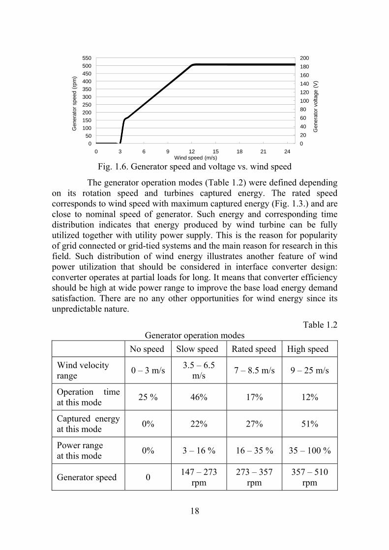
The rotation speed dependence on wind velocity of the generator and its voltage characteristics is illustrated in Fig. 1.6. It clearly demonstrates the wide range of generators output voltage and wind turbine operation modes (at maximal turbine power in variable speed mode).
18
0
20
40
60
80
100
120
140
160
180
200
0
50
100
150
200
250
300
350
400
450
500
550
0 3 6 9 12 15 18 21 24
Gen
erat
or v
olta
ge (
V)
Gen
erat
or s
peed
(rp
m)
Wind speed (m/s) Fig. 1.6. Generator speed and voltage vs. wind speed
The generator operation modes (Table 1.2) were defined depending on its rotation speed and turbines captured energy. The rated speed corresponds to wind speed with maximum captured energy (Fig. 1.3.) and are close to nominal speed of generator. Such energy and corresponding time distribution indicates that energy produced by wind turbine can be fully utilized together with utility power supply. This is the reason for popularity of grid connected or grid-tied systems and the main reason for research in this field. Such distribution of wind energy illustrates another feature of wind power utilization that should be considered in interface converter design: converter operates at partial loads for long. It means that converter efficiency should be high at wide power range to improve the base load energy demand satisfaction. There are no any other opportunities for wind energy since its unpredictable nature.
Table 1.2 Generator operation modes
No speed Slow speed Rated speed High speed
Wind velocity range
0 – 3 m/s 3.5 – 6.5
m/s 7 – 8.5 m/s 9 – 25 m/s
Operation time at this mode
25 % 46% 17% 12%
Captured energy at this mode
0% 22% 27% 51%
Power range at this mode
0% 3 – 16 % 16 – 35 % 35 – 100 %
Generator speed 0 147 – 273
rpm 273 – 357
rpm 357 – 510
rpm

19
Topology analysis of interface converters for WSVT
There are a lot of interface converter topologies without galvanic isolation studied in literature, but only few researches are devoted to topologies with high frequency isolation for micro and small wind applications [9,14,16]. In [9] the authors have proposed a buck type isolated DC/DC converter (Fig. 1.7.)
Fig. 1.7. Buck type isolated DC/DC converter
Stabilization of the second DC link voltage is obtained with the buck type isolated DC/DC converter by means of duty cycle variation. The main drawback of buck type converter utilization in wind applications is high currents in the transformer’s primary winding and HF inverter switching devices at rated wind speeds. Moreover such topology does not offer possibility to use low voltage transistors: they should withstand the maximal voltage of the first DC link voltage UC1 (Fig. 1.8). Fig. 1.8. illustrates the simulation results of buck type interface converter at 1250 W load. One can see that inductor current IL1 is enormous for 1.3kW converter and will lead to high power losses is HF inverter switches, inductor and
Fig. 1.8. The main current and voltage waveforms of buck type isolated DC/DC interface converter at 1250 W load

20
transformer primary windings. On the other hand there will be high switching losses at cut-in conditions due to high power transistor utilization in HF inverter. The inductor current IL1, HF inverter output voltage U1 and transformer primary voltage UTr,prim and both DC link voltage UC1, UC2
waveforms of buck type interface converter at 40 W load are demonstrated in Fig. 1.9. Previously mentioned disadvantages make this topology unattractive for wind applications.
Fig. 1.9. The main current and voltage waveforms of buck type isolated DC/DC interface converter at 40 W load
In [16] the authors have proposed a one-phase soft-switched dual LCL DC/AC converter (Fig. 1.10.).
Fig. 1.10. A HF isolated dual-bridge LCL resonant converter
This converter utilizes a controlled rectifier for generator voltage rectification and DC link voltage stabilization. The output voltage of series connected HF transformers is rectified into DC voltage with diode bride. This rectified voltage (HF transformer output voltage too) contains ripple with grid frequency. The switching frequency of grid side inverter is reduced in

21
such way. This pulsating voltage is filtered by low pass LCL filter and after is inverted with line connected inverter (LCI) The switches of LCI is commutated when line voltage cross the zero point. High switching frequency of the HF inverter (100 kHz) helps to reduce the low pass LCL filter size, but low switching frequency of LCI eliminates the switching loss in this converter part. The main disadvantage of dual-bridge LCL resonant converter is big amount of controlled switches (Table 1.3) that needs driver circuits and appropriate control unit. Another disadvantage is reported efficiency of proposed converter prototype: only 90 % at 500 W (nominal load) and 83 % at 250 W load [34]. Reduced efficiency at partial load will significantly reduce the total energy transmitted to the grid that can be the worst case for wind turbine applications. Analysis of two topologies with HF isolation studied in literature for VSWT applications shows the significant disadvantages in terms of efficiency issues and complexity. Buck type isolated interface converter has relative simple circuit, but high current stress on semiconductor devices in HF inverter and primary winding of transformer can lead to big converter size and high price. Dual bride LCL resonant converter offer soft switching approach at HF isolation and LCI stages, but still has high circuit complexity and low reported efficiency. For these reasons the new HF isolated converter topology for wind applications is proposed. Due to voltage and power characteristics of the PMSG based VSWT an interface converter topology utilizing converters with boost properties seams the most suitable solution for this application.
Table 1.3 Component count in two reviewed topologies
Topology Elements
Buck type converter Dual bridge LCL resonant converter
Transistors 8 18 Diodes 10 4 Transformers 1 2 Inductors 1 2 Capacitors 2 3
22
2. NEW ISOLATED CONVERTER TOPOLOGY
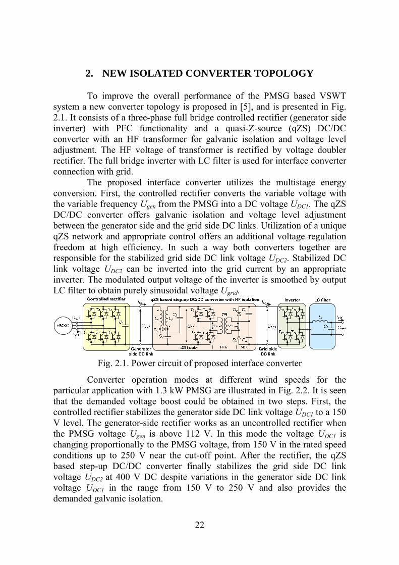
To improve the overall performance of the PMSG based VSWT system a new converter topology is proposed in [5], and is presented in Fig. 2.1. It consists of a three-phase full bridge controlled rectifier (generator side inverter) with PFC functionality and a quasi-Z-source (qZS) DC/DC converter with an HF transformer for galvanic isolation and voltage level adjustment. The HF voltage of transformer is rectified by voltage doubler rectifier. The full bridge inverter with LC filter is used for interface converter connection with grid. The proposed interface converter utilizes the multistage energy conversion. First, the controlled rectifier converts the variable voltage with the variable frequency Ugen from the PMSG into a DC voltage UDC1. The qZS DC/DC converter offers galvanic isolation and voltage level adjustment between the generator side and the grid side DC links. Utilization of a unique qZS network and appropriate control offers an additional voltage regulation freedom at high efficiency. In such a way both converters together are responsible for the stabilized grid side DC link voltage UDC2. Stabilized DC link voltage UDC2 can be inverted into the grid current by an appropriate inverter. The modulated output voltage of the inverter is smoothed by output LC filter to obtain purely sinusoidal voltage Ugrid.
Fig. 2.1. Power circuit of proposed interface converter
Converter operation modes at different wind speeds for the particular application with 1.3 kW PMSG are illustrated in Fig. 2.2. It is seen that the demanded voltage boost could be obtained in two steps. First, the controlled rectifier stabilizes the generator side DC link voltage UDC1 to a 150 V level. The generator-side rectifier works as an uncontrolled rectifier when the PMSG voltage Ugen is above 112 V. In this mode the voltage UDC1 is changing proportionally to the PMSG voltage, from 150 V in the rated speed conditions up to 250 V near the cut-off point. After the rectifier, the qZS based step-up DC/DC converter finally stabilizes the grid side DC link voltage UDC2 at 400 V DC despite variations in the generator side DC link voltage UDC1 in the range from 150 V to 250 V and also provides the demanded galvanic isolation.

23
Fig. 2.2. General operation modes of the interface converter
The series of simulations are carried out to validate the proposed operation modes. The theoretical assumptions are experimentally validated by help of the 1.3 kW test setup (Fig. 2.3.) assembled in accordance with schematics presented in Fig. 2.1. The generator side rectifier was powered with 1.3 kW PMSG with 8 pole pairs and loaded with electronic load. The qZS DC/DC converter was tested with fixed input voltages and fixed loads. A general specifications of experimental setup is collected in Table 2.1.
Fig. 2.3. Laboratory test setup of interface converter

24
Table 2.1 General specifications of test setup
Component Value or type PMSG Phase resistance 1.2 Ω Phase inductance 5 mH Interface converter T1…T6 600 V/48 A IGBT (IXSH24N60AU1) T7…T10 600 V/12 A IGBT (G4PC30UD) D1 600 V/120 A fast diode (STTH200L06TV) D2, D3 1.2 kV /60 A FRED (DSEI2x61-12B) Capacitance of C1 470 uF Inductance of L1 and L2 1.2 mH Capacitance of C2 and C3 60 uF HF transformer turns ratio 1 : 1.2 Capacitance of C4 and C5 25 uF
Generator side converter
The control principle of generator side inverter is built according to the PWM method of control (Fig. 2.4a).
a)
Igen&
Igen_ref +
-
D Q
Q
10 kHz
T1
T2
Switch Control Block
D Q
Q
b)
Fig. 2.4. Control system of generator side inverter (for one phase)

25
The input values of regulator enter the instantaneous value of generator side DC link voltage UDC1 and the reference voltage UC_ref, equal to the necessary voltage level. In order to escape pulsations of voltage across capacitors, only constant component of voltage is used. Further voltage error is feed to the PI regulator, whose output determines the amplitude of reference current. The form of reference current is determined by supply voltage, as a result the current is in-phase to the voltage. Nonlinear element of the type “saturation” is used for limiting the amplitude of current. Further reference current will be given to the controller of the commutation of power switches. The unit of the commutation of power switches is built according to the method of vector control of power switches. In Fig. 2.4b the scheme of controller is represented. The flowchart of the control algorithm (Fig. 2.5) illustrates the control process of the generator side inverter.
Fig. 2.5. Flowchart of the control algorithm for the generator side inverter
The controlled rectifier operates in the PFC mode and boosts the generator voltage to 150 V level when the line voltage of the generator is below the level of 112 V. The PFC signal generation is stopped and the uncontrolled rectification mode takes place, when the generator line voltage is higher than 112 V. In order to check the control algorithm simulation has been carried out. The first simulation was performed at the generator voltage Ugen = 53 V and 40 W load (Fig. 2.6.). At the time moment t=0.1 s, the regulator is switched on and the capacitor voltage level is gradually increased up to reference level 150 V. The amplitude of current is simultaneously raised up to the level that corresponds to the consumed power in this case. It is evident that current shape follows generation voltage. THD is about 31%. There are

26
high frequency ripple that can be reduced by additional serial inductance or increased switching frequency of power switches. The second simulation was performed at rated generator speed conditions, with the generator speed at 315 rpm and turbine power at 330 W. At this point the amplitude of the generator voltage Ugen is 150 V and boost control are not needed (Fig. 2.7). At the time moment t=0.1 s, the regulator is switched on. The generator current doesn’t follow the voltage shape in this mode that can be considered as a disadvantage. Such situation is caused by relative low voltage difference between DC link and generator voltage. THD is improved from 41% to 31%.
Fig. 2.6. Generator side DC link voltage UDC1, PMSG current ia, and voltage Ugen and filtered generator voltage Uref at 40 W
Fig. 2.7. Generator side DC link voltage UDC1, PMSG current ia, and voltage Ugen and filtered generator voltage Uref at 330 W

27
The third simulation was performed at maximal speed and power of the PMSG: 510 rpm and 1250 W, respectively (Fig. 2.8). Since the nominal speed of the generator is 375 rpm, it was required to verify the generator’s ability to produce the power necessary at that speed. The amplitude of the generator’s output voltage Ugen reaches 250 V. PFC control is not used in this mode and THD of generator current is about 28%.
Fig. 2.8. Generator-side DC link voltage UDC1, PMSG current ia and voltage
Ugen, at 1250 W A series of experiments were performed to verify the proper operation of the PMSG with the controller. Control was realized by controlling six transistors with a fixed duty cycle at 20 kHz switching frequency. It should be noted, that additional serial inductance was added in order to smooth output voltage of generator. It is necessary for proper measurement of voltage that is used as reference signal in control system. Additionally the inductors ensure lower current ripple.
Fig. 2.9. Laboratory test setup for generator side inverter tests

28
The first experimental test was performed at rated speed conditions, with the generator speed at 315 rpm and turbine power at 330 W. At this point the amplitude of the generator voltage Ugen is 150 V and boost control are not needed (Fig. 2.10.). Opposite site of this situation is current shape that doesn’t coincident with voltage shape.
Fig. 2.10. Experimental results: PMSG current (a) and generator side DC link
voltage and current (b) at 330 W
The second test was performed at maximal speed and power of the PMSG: 510 rpm and 1250 W, respectively (Fig. 2.11.). Since the nominal speed of the generator is 375 rpm, it was required to verify the generator’s ability to produce the power necessary at that speed. The amplitude of the generator’s output voltage reaches 250 V. PFC control is not possible in this mode.
Fig. 2.11. Experimental results: PMSG voltage and current (a) and generator-
side DC link voltage and current (b) at 1250 W
From experimental results is concluded that the controlled rectifier operates in close to expected mode. Limitations connected with voltage distortion during transistor switching can be eliminating by improvement of signal filtering.

29
qZS based DC/DC converter with HF isolation
The qZSI is derived from a traditional Z-source inverter (ZSI) [21] and has two distinctive advantages as compared to ZSI, such as continuous DC current drawn from the source and lower operating voltage of the capacitor C2 [1]. Practically, qZSI is a traditional PWM inverter coupled with a special quasi-Z-source network (qZS-network). As seen from Fig. 2.12., the qZS-network consists of two capacitors C1 and C2, two inductors L1 and L2 and a diode D1.
UDC1
L1 L2
UDC2
TRD2
D3
C3
C1
C2
D1
qZS based step-up DC/DC converter with HF isolation
C4
UDC
IDC1 IDC2
T1
T2
T3
T4
UTR, pr UTR, sec
qZS-inverter HF tr VDR
*
*
Fig. 2.12. qZS based step-up DC/DC converter with HF isolation
The high-frequency step-up isolation transformer provides the required galvanic isolation of the input and output sides of the converter. Transformer’s primary winding is connected to the output terminals of qZSI, while the secondary side is connected to the voltage doubler rectifier (VDR). The main function of the HF isolation converter is to stabilize the grid side inverter voltage UDC2 despite the variations of the first DC link voltage UDC1. By keeping the DC-link voltage constant the PWM inverter could be operated with a fixed duty cycle value, thus ensuring constant volt-second and flux swing of the isolation transformer. In accordance with the input voltage (generator side DC link voltage) the operating modes of the proposed DC/DC converter could be broadly categorized as non-shoot-through and shoot-through operating modes (Fig. 2.13).
Fig. 2.13. Flow chart of operating modes of qZSI based DC/DC converter

30
If the voltage is equal or higher than the desired DC-link voltage, the converter starts to operate in the non-shoot-through mode. In this mode the qZSI operates as a traditional VSI. The operating period of the qZSI in the non-shoot-through mode consists of the combination of active and zero states. During active (energy transfer) states the power switches of the inverter bridge are gated alternately in pairs (T1, T4 and T2, T3) and power is transferred from the DC-link to the isolation transformer (Fig. 2.14.). During zero states the primary winding of the isolation transformer is shorted either through the upper switches (T1, T3) or the bottom switches (T2, T4) of the inverter bridge (Fig. 2.15) and the transformer sees no voltage from the inverter.
Fig. 2.14. Equivalent circuit during active states: positive (a) and negative (b) half-cycles
Fig. 2.15. Equivalent circuit during zero-states created by upper (a) and lower (b) switches
The operating period of the PWM inverter during the non-shoot-through mode consists of an active state tA and a zero state tZ:
ZA ttT . (3)
If the generator side DC link voltage drops below the predefined DC link voltage level UDC the converter begins to operate in the shoot-through mode. The varying voltage of the generator side DC link is preregulated to a desired DC-link voltage level by adjusting the shoot-through duty cycle. Afterwards the isolation transformer is being supplied from the inverter with a voltage of constant amplitude, as described in the previous section.
31
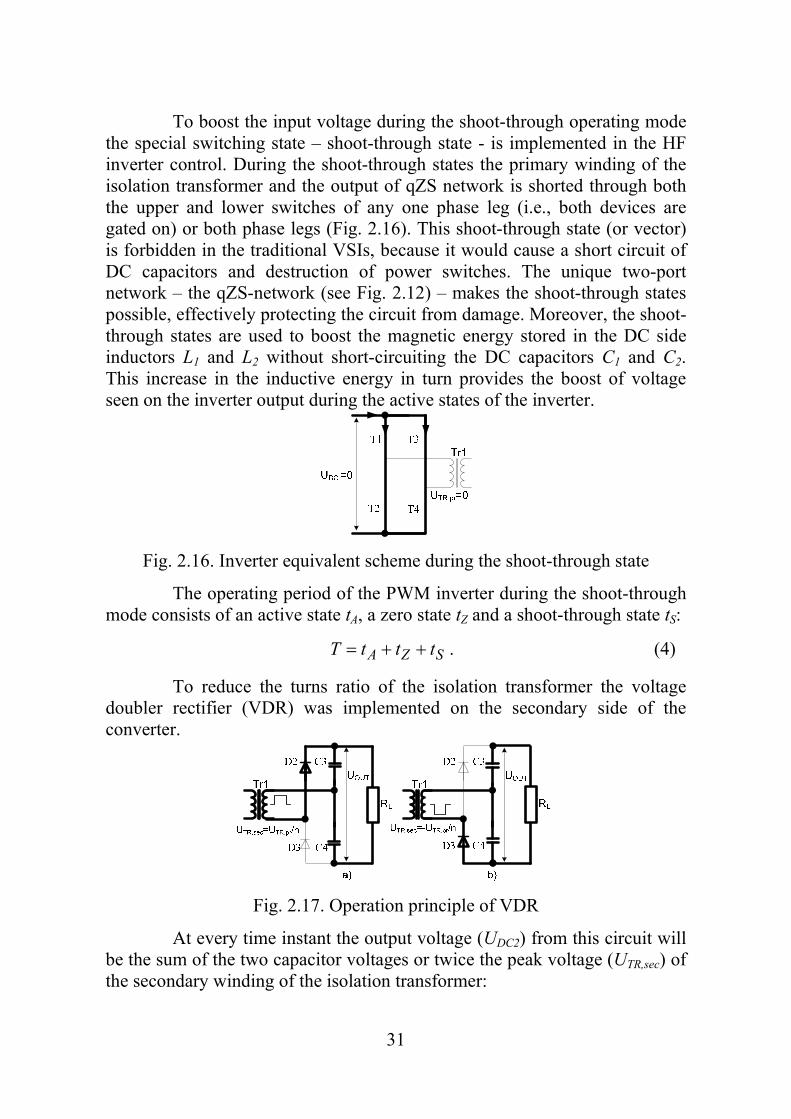
To boost the input voltage during the shoot-through operating mode the special switching state – shoot-through state - is implemented in the HF inverter control. During the shoot-through states the primary winding of the isolation transformer and the output of qZS network is shorted through both the upper and lower switches of any one phase leg (i.e., both devices are gated on) or both phase legs (Fig. 2.16). This shoot-through state (or vector) is forbidden in the traditional VSIs, because it would cause a short circuit of DC capacitors and destruction of power switches. The unique two-port network – the qZS-network (see Fig. 2.12) – makes the shoot-through states possible, effectively protecting the circuit from damage. Moreover, the shoot-through states are used to boost the magnetic energy stored in the DC side inductors L1 and L2 without short-circuiting the DC capacitors C1 and C2. This increase in the inductive energy in turn provides the boost of voltage seen on the inverter output during the active states of the inverter.
Fig. 2.16. Inverter equivalent scheme during the shoot-through state
The operating period of the PWM inverter during the shoot-through mode consists of an active state tA, a zero state tZ and a shoot-through state tS:
SZA tttT . (4)
To reduce the turns ratio of the isolation transformer the voltage doubler rectifier (VDR) was implemented on the secondary side of the converter.
Fig. 2.17. Operation principle of VDR
At every time instant the output voltage (UDC2) from this circuit will be the sum of the two capacitor voltages or twice the peak voltage (UTR,sec) of the secondary winding of the isolation transformer:

32
sec,2 2 TRDC UU . (5)
Operating principle of the qZSI during the shoot-through mode
In the shoot-through operation mode there are two general power conversion states: shoot-through (voltage boost in primary side) and active (power transfer to secondary side) state. The equivalent schemes of the qZSI during the shoot-through and active state are presented in Fig. 2.18.[30]. All the polarities, voltages and currents are defined with arrows and polarity signs.
(a)
(b)
Fig. 2.18. Equivalent circuits of the qZSI during the shoot-through (a) and active (b) states

33
From Fig. 2.18.a, which represents the shoot-through state of the qZSI with duration tS, one can obtain
1221 , CLINCL UUUUu , (6)
211,0 CCDDC UUuu . (7)
From Fig. 2.18.b, which represents the active state of the qZSI with the duration of (T-tS), we can obtain
2211 , CLCINL UuUUu , (8)
0, 12121 DCCLCDC uUUuUu . (9)
At the steady state the average voltage of the inductor over one switching period is zero. Thus, from equations (6) and (8) we can obtain
0
0
2122
1211
T
)U()t(T)(UtuU
T
)U(U)t(T)U(UtuU
CSCSLL
CINSINCSLL
. (10)
Accordingly,
INS
S
C U
T
tT
t
U
21
1
1 and INS
S
C U
T
tT
t
U
21
2 . (11)
The peak DC-link voltage across the inverter bridge is
ININS
CCDC UBU
T
tUUu
21
1ˆ 21 , (12)
where B - the boost factor of the qZSI:
T
tB
S
21
1. (13)
The operating voltages and average currents of the qZSI during active and shoot-through states are shown in Table 2.2. For the better appearance the shoot-through time interval tS was replaced with the shoot-through duty cycle DS=tS /T.

34
Table 2.2 Operating voltages and average currents of the qZSI
State Active Shoot-through
Inductor voltage (uL1=uL2) INS
S UD
D
21 IN
S
S UD
D
21
1
DC-link voltage (uDC) INS
UD
21
1 0
DC-link current (IDC,av)
IN
S
U
DP 21 S
IND
U
P
2
Diode D1 voltage (uD1) 0 INS
UD
21
1
Capacitor C1 voltage (UC1) INS
S UD
D
21
1
Capacitor C2 voltage (UC2) INS
S UD
D
21
Input current (IIN,av) INU
P
Inductor current (IL1,av=IL2,av) INU
P
Capacitor current (IC1,av=IC2,av) IDC,av - IL1,av
Diode current (ID1,av) 2·IL1,av - IDC,av
Discontinuous conduction mode of qZS inverter
As it is seen from Fig. 2.1., the proposed qZS-inverter has the input inductor L1 that buffers the source current. It means that in the continuous conduction mode (CCM) the input current never drops to zero during the shoot-through states. However, in the case of small loads, relatively low switching frequency and low inductance values of L1 and L2, the qZS-inverter could start to operate in the discontinuous conduction mode (DCM) and the input current falls to zero during some part of the switching period. In the current application, similar conditions could appear during the operation of a wind turbine near the cut-in region, when the PMSG power drops to minimum [8].

35
The operating period of the qZS-inverter in the DCM generally consists of an active state tA, a shoot-through state tS and a discontinuous conduction state tD
1 DSADSA DDDT
t
T
t
T
t, (14)
where DA - duty cycles of active; DS - shoot-through state; DD - discontinuous conduction state. The equivalent circuit of the discontinuous conduction state is similar to the active states (Fig. 2.18.b), the only difference is that the diode D1 stops conducting at that time interval. The equivalent circuits of the qZS-inverter in the shoot-through and active states remain the same as in Fig. 2.18. When the converter is in a discontinuous conduction state tD, the voltages of the inductors L1 and L2 are equal to zero. For the DCM, Eq. (10) could be extended as follows:
00)()(
00)()(
3222
211311
DCACSLL
DCDCADCCSLL
DUDUDuU
DUUDUUDuU, (15)
where DA - duty cycles of active; DS - shoot-through state; DD - discontinuous conduction state. In contrast to the CCM the operating voltage of the capacitor C2 during the DCM will increase:
.UDD
DDU DC
DS
DSC 12 21
1
(16)
That, in turn, will lead to an increased peak value of the DC link voltage during the DCM, causing the “overboost effect” of the input voltage:
132 21
1ˆDC
DS
DCCDC(DCM) U
DD
DUUU
. (17)
Simulation and experimental results.
In the first test the generator-side DC link voltage was set to 150 V that corresponds to the cut-in and rated wind speed conditions. The load that corresponds to the turbine power at cut-in is 40 W. The qZS based DC/DC converter operates in the discontinuous conduction mode (DCM) at such load. Since the voltage boost of the qZS based DC/DC converter is higher at
36
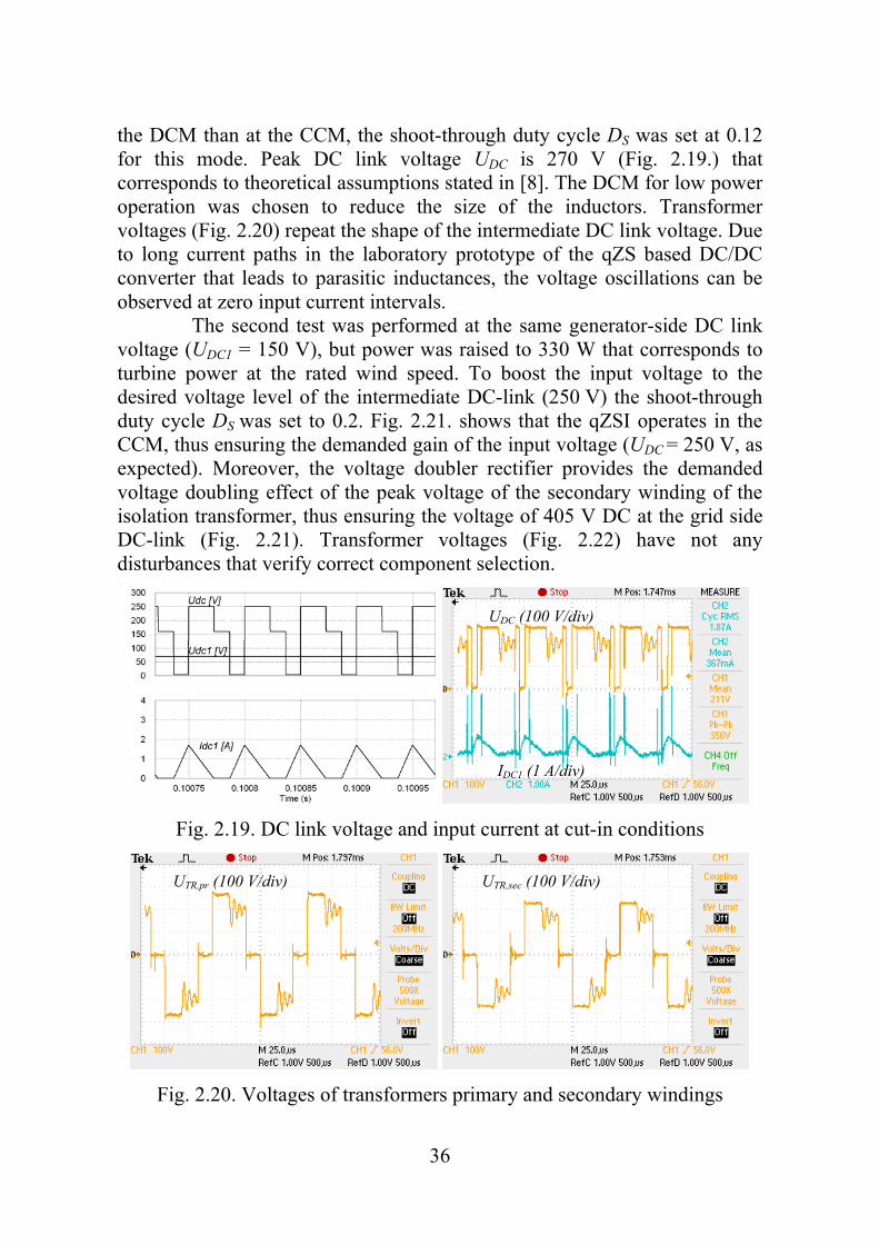
the DCM than at the CCM, the shoot-through duty cycle DS was set at 0.12 for this mode. Peak DC link voltage UDC is 270 V (Fig. 2.19.) that corresponds to theoretical assumptions stated in [8]. The DCM for low power operation was chosen to reduce the size of the inductors. Transformer voltages (Fig. 2.20) repeat the shape of the intermediate DC link voltage. Due to long current paths in the laboratory prototype of the qZS based DC/DC converter that leads to parasitic inductances, the voltage oscillations can be observed at zero input current intervals. The second test was performed at the same generator-side DC link voltage (UDC1 = 150 V), but power was raised to 330 W that corresponds to turbine power at the rated wind speed. To boost the input voltage to the desired voltage level of the intermediate DC-link (250 V) the shoot-through duty cycle DS was set to 0.2. Fig. 2.21. shows that the qZSI operates in the CCM, thus ensuring the demanded gain of the input voltage (UDC = 250 V, as expected). Moreover, the voltage doubler rectifier provides the demanded voltage doubling effect of the peak voltage of the secondary winding of the isolation transformer, thus ensuring the voltage of 405 V DC at the grid side DC-link (Fig. 2.21). Transformer voltages (Fig. 2.22) have not any disturbances that verify correct component selection.
Fig. 2.19. DC link voltage and input current at cut-in conditions
Fig. 2.20. Voltages of transformers primary and secondary windings
UDC (100 V/div)
IDC1 (1 A/div)
UTR,pr (100 V/div) UTR,sec (100 V/div)

37
Fig. 2.21. DC link voltage and current at rated speed conditions (330 W)
Fig. 2.22. Voltages of transformers primary and secondary windings The third test was performed at the maximum generator-side DC link voltage (UDC1 = 250 V), which corresponds to the maximal power of the turbine (1250 W). At this operating point, when the input voltage equals the desired intermediate DC-link voltage (UDC1 = UDC = 250 V), the shoot-through states were eliminated (DS = 0) and the converter operated as a traditional VSI (Fig. 2.23.). In that case the isolation transformer is supplied with voltage pulses with the amplitude value equal to the generator-side DC link voltage. The voltage waveforms of the isolation transformer in this operation point are similar to those presented in Fig. 2.24.
Fig. 2.23. DC link voltage and input current at rated wind speed (1250 W)
UDC (100 V/div)
IDC1 (2 A/div)
UTR,pr (100 V/div) UTR,sec (100 V/div)
UDC (100 V/div)
IDC1 (2 A/div)

38
Fig. 2.24. Voltages of transformers primary and secondary windings
Interface converter for micro turbines
To reduce the overall cost of the system and taking into account “overbost” effect of qZS DC/DC converter was offered simplified interface converter (Fig. 2.25.). Elimination of controlled rectifier allows utilization of simpler control circuit.
Fig. 2.25. Power circuit for wind turbine systems of micro power level
The necessary boost is obtained only by qZS DC/DC converter. Converter operation modes at different wind speeds for the particular application with 1.3 kW PMSG are illustrated in Fig. 2.26. First, the rectifier converts the variable voltage with the variable frequency Ugen from the PMSG into a DC voltage UDC1. The generator side DC link voltage range is between 70 V at cut-in conditions and 250 V in constant speed mode.
Fig. 2.26. Operation modes of simplified interface converter
UTR,pr (100 V/div) UTR,sec (100 V/div)
39
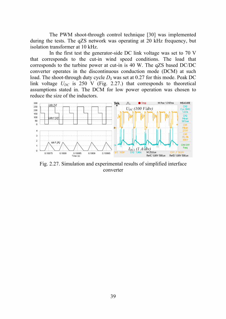
The PWM shoot-through control technique [30] was implemented during the tests. The qZS network was operating at 20 kHz frequency, but isolation transformer at 10 kHz. In the first test the generator-side DC link voltage was set to 70 V that corresponds to the cut-in wind speed conditions. The load that corresponds to the turbine power at cut-in is 40 W. The qZS based DC/DC converter operates in the discontinuous conduction mode (DCM) at such load. The shoot-through duty cycle DS was set at 0.27 for this mode. Peak DC link voltage UDC is 250 V (Fig. 2.27.) that corresponds to theoretical assumptions stated in. The DCM for low power operation was chosen to reduce the size of the inductors.
Fig. 2.27. Simulation and experimental results of simplified interface converter
UDC (100 V/div)
IDC1 (1 A/div)

40
3. QZS DC/DC Converter with improved boost properties
Improved quasi-Z-source based back-to-back interface converter is introduced by the utilization of the switched inductor quasi-Z-source network (Fig. 3.1.). The new topology offers the increased voltage boost capability of the grid-side inverter.
Fig. 3.1. New proposed switched inductor quasi-Z-source based back-to-back
converter for VSWTs with PMSG The proposed SL qZS network consists of three inductors (L1…L3), four diodes (D1…D4) and two capacitors (C1 and C2). Inductors L2 and L3 can be implemented as coupled inductors. Coupled with the grid side PWM inverter, the SL qZS network forms the SL quasi-Z-source inverter (SL qZSI). Similarly to the traditional qZSI [75], the SL qZSI has two main types of operational states at the DC side: non-shoot-through states and shoot-through states. Fig. 3.2. shows the equivalent circuits of the SL qZSI operating in the CCM for the shoot-through (a) and active (b) states. At the steady state the average voltage of the inductors over one operating period is zero:
011 Tt
t
LL dtuU ; 022 Tt
t
LL dtuU ; 033 Tt
t
LL dtuU . (18)
Based on that fact and defining the shoot-through duty cycle as DS and the non-shoot-through duty cycle as (1-DS), the inductors voltages over one operating period could be represented as
0)2
)(1(
0))(1()(
213232
112111
CSCSLLLL
CDCSCDCSLL
UDUDuuUU
UUDUUDuU. (19)
The peak inverter input voltage UDC2 are derived from the steady state analysis.
121
2)21(
)1(ˆDC
SS
SDCDC UB
DD
DUU
. (20)

41
The voltage conversion ratio G of the whole inverter can be expressed by
BMU
UG
DC
mgrid 1
, (21)
where M - is the modulation index.
The modulation index is connected with the shoot-through duty cycle by the following relation [1]:
SDM 1 . (22)
(a)
‐+
(b)
Fig. 3.2. Equivalent circuits of the SL qZSI: during shoot-through state (a) and during active (non-shoot-through) state (b)
In Fig. 3.3. the voltage boost factor B and the voltage conversion ratio G of the traditional qZSI are compared with those of the proposed SL

42
qZSI. It is seen that the shoot-through duty cycle DS for the SL qZSI is lower than for traditional qZSI at the same voltage conversion ratio G (Fig. 3.3.b). This is significant feature of the SL qZSI that allows expand the grid voltage regulation possibilities at reduced grid side DC link peak voltage UDC2p.
0
1
2
3
4
5
6
7
0 0,1 0,2 0,3
Boostfactor, (B)
Shooth‐through, (Ds)
(a)
0
1
2
3
4
5
0 0,1 0,2 0,3
Vol
tage
con
vert
ion
rati
o, (
G)
Shooth-through, (Ds)
(b)
Fig. 3.3. Boost factor B (a) and voltage conversion ratio G (b) as functions of the shoot-through duty cycle for qZSI andd SL qZSI
Operation modes of the interface converter

43
Based on the specifications of the PMSG the operation modes of the proposed back-to-back interface converter are presented in Fig. 8. The necessary voltage boost is obtained in two steps. The PWM rectifier stabilizes the DC link voltage UDC1 to a 150 V level when the generator voltage is below 112 V. This operation mode of the converter is called a PWM mode. The transferred power of the converter lies between 40 W and 330 W at this mode. The controlled rectifier works as diode rectifier when the generator voltage Ugen is above 112 V. In this mode the DC link voltage is changed proportionally to the generator voltage, at the range from 150 V in rated generator speed conditions up to 250 V at the maximal speed.
Fig. 3.4. Operation modes of the proposed converter
The SL qZS network with appropriate inverter control is stabilizing the peak value of the inverter side DC link voltage UDC2 to 490 V despite the voltage variations on the generator side DC link. The inverter input voltage UDC2 regulation is obtained by changing the shoot-through duty cycle Ds [5]. The peak value of the inverter side DC link voltage UDC2 is so high due to lower modulation index M if compared with voltage source inverters. Modulation index is limited by shoot-through states implemented in SL qZSI. The variation range of the voltage conversion ratio G lies between 1.44 and 2.4 that corresponds to the generator side DC link voltage UDC1 range from 250 V up to 150 V. Since the modulation index M and the boost factor B are the functions of DS, the appropriate values of shoot-through can be found for minimum and maximum G values. The variation range of the shoot-through duty cycle DS is from 0.17 in maximum speed conditions to 0.27 in the cut-in speed conditions.
Analysis of simulation and experimental results
44
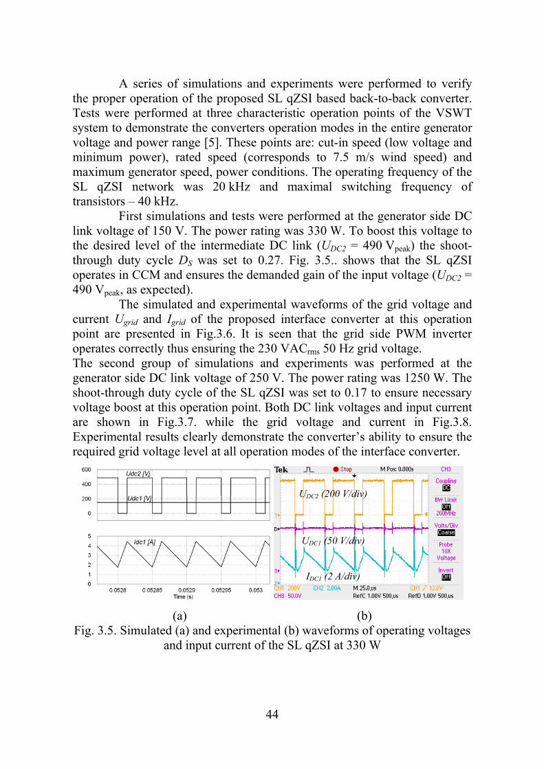
A series of simulations and experiments were performed to verify the proper operation of the proposed SL qZSI based back-to-back converter. Tests were performed at three characteristic operation points of the VSWT system to demonstrate the converters operation modes in the entire generator voltage and power range [5]. These points are: cut-in speed (low voltage and minimum power), rated speed (corresponds to 7.5 m/s wind speed) and maximum generator speed, power conditions. The operating frequency of the SL qZSI network was 20 kHz and maximal switching frequency of transistors – 40 kHz. First simulations and tests were performed at the generator side DC link voltage of 150 V. The power rating was 330 W. To boost this voltage to the desired level of the intermediate DC link (UDC2 = 490 Vpeak) the shoot-through duty cycle DS was set to 0.27. Fig. 3.5.. shows that the SL qZSI operates in CCM and ensures the demanded gain of the input voltage (UDC2 = 490 Vpeak, as expected). The simulated and experimental waveforms of the grid voltage and current Ugrid and Igrid of the proposed interface converter at this operation point are presented in Fig.3.6. It is seen that the grid side PWM inverter operates correctly thus ensuring the 230 VACrms 50 Hz grid voltage. The second group of simulations and experiments was performed at the generator side DC link voltage of 250 V. The power rating was 1250 W. The shoot-through duty cycle of the SL qZSI was set to 0.17 to ensure necessary voltage boost at this operation point. Both DC link voltages and input current are shown in Fig.3.7. while the grid voltage and current in Fig.3.8. Experimental results clearly demonstrate the converter’s ability to ensure the required grid voltage level at all operation modes of the interface converter.
(a) (b) Fig. 3.5. Simulated (a) and experimental (b) waveforms of operating voltages
and input current of the SL qZSI at 330 W
UDC2 (200 V/div)
UDC1 (50 V/div)
IDC1 (2 A/div)

45
(a) (b)
Fig. 3.6. Simulated (a) and experimental (b) waveforms of the grid voltage and current at 330 W
(a) (b)
Fig. 3.7. Simulated a) and experimental b) waveforms of qZSI voltages and current at 1250W load
(a) (b)
Fig. 3.8. Simulated a) and experimental b) waveforms of SL qZSI output voltage and current at 1250W load
Ugrid (200 V/div)
Igrid (2 A/div)
Ugrid (200 V/div)
Igrid (5 A/div)
UDC2 (200 V/div)
UDC1 (50 V/div)
IDC1 (2 A/div)

46
4. CONCLUSIONS AND FUTURE WORK
The family of qZS based interface converters for PMSG based VSWT applications are offered in this thesis The qZS based interface converter with generator side inverter was offered for PMSG based VSWT systems in small power range, but topology with uncontrolled rectifier for micro power range. The new topology of qZS converter with switched inductors was offered and analysed. The main target for this topology is converters with ultra wide input voltage range, thanks to enhanced boost performance of this converter. The main advantage of the proposed converter is the enhanced output voltage regulation properties thanks to the new SL qZS network implemented. The proposed topology could be implemented in the residential PMSG based wind turbines with power rating up to 15 kW. The future work should be concentrated on brand new semiconductor switch utilisation in converters for future efficiency optimization and higher utilization of renewable energy.

47
REFERENCES
1. Anderson, J., Peng, F.Z., “Four Quasi-Z-Source Inverters”, 2008 IEEE Power Electronics Specialist Conference, PESC 2008, Rhodes, Greece, 2008, pp. 2743-2749.
2. Arifujjaman, M.; Iqbal, M.T.; Quaicoe, J.E.; "A comparative study of the reliability of the power electronics in grid connected small wind turbine systems," Canadian Conference on Electrical and Computer Engineering, 2009. CCECE '09, pp.394-397, 3-6 May 2009
3. Bisenieks, L.; Galkins, I.; “Estimation of Converter Topologies for Small Wind Turbine,” 9th international symposium, Topical Problems in the Field of Electrical and Power Engineering, Doctoral School of Energy and Geotechnology II, 2010, pp. 25 – 28, January 2010
4. Bisenieks, L.; Vinikkov, D.; Galkin, I.; “New Converter for Interfacing PMSG based Small-Scale Wind Turbine with Residential Power Network,” 10th International Conference on Environment and Electrical Engineering. 2011, EEEIC2011, pp. 869 – 872, 8-11 May 2011
5. Bisenieks, L.; Vinnikov, D.; Galkin, I.; “New Converter for Interfacing PMSG based Small-Scale Wind Turbine with Residential Power Network” 7th International Conference-Workshop Compability and power Electronics, pp. 1 – 6, June 2011
6. Bisenieks, L.; Vinnikov, D.; Zakis, J. “Analysis of Operating Modes of the Novel Isolated Interface Converter for PMSG Based Wind Turbines,” International Conference on Power Engineering, Energy and Electrical Drives, 2011, POWERENG2011, pp.1 – 8, 11 – 13 May 2011”
7. Blaabjerg, F.; Teodorescu, R.; Liserre, M.; Timbus, A.V.; "Overview of Control and Grid Synchronization for Distributed Power Generation Systems," IEEE Transactions on Industrial Electronics” vol.53, no.5, pp.1398-1409, Oct. 2006
8. Cristina L. Archer and Mark Z. Jacobson. Evaluation of global wind power, 2005. Journal Of Geophysical Research, Vol. 110
9. Darbyshire, J.; Nayar, C.V. "Modelling, simulation and testing of grid connected small scale wind systems," Australasian Universities Power Engineering Conference, 2007. AUPEC 2007, pp.1-6, 9-12 Dec. 2007
10. Dehghan, S.M.; Mohamadian, M.; Varjani, A.Y.; "A New Variable-Speed Wind Energy Conversion System Using Permanent-Magnet Synchronous Generator and Z-Source Inverter," IEEE Transactions on Energy Conversion , vol.24, no.3, pp.714-724, Sept. 200
11. Fujin Deng; Zhe Chen; , "Power control of permanent magnet generator based variable speed wind turbines," International Conference on Electrical Machines and Systems, 2009. ICEMS 2009, vol.pp.1-6, 15-18 Nov. 2009
12. http://www.windenergymarket.de/en/wind-turbines/ 13. Leon, A.E.; Mauricio, J.M.; Solsona, J.A.; Gómez-Expósito, A.; , "Adaptive
Control Strategy for VSC-Based Systems Under Unbalanced Network

48
Conditions," IEEE Transactions on Smart Grid, vol.1, no.3, pp.311-319, Dec. 2010
14. Li, H.; Chen, Z.; "Overview of different wind generator systems and their comparisons," IET, Renewable Power Generation, vol.2, no.2, pp.123-138, June 2008
15. Li, H.; Chen, Z.; "Overview of different wind generator systems and their comparisons," IET Renewable Power Generation, vol.2, no.2, pp.123-138, June 2008
16. Li, X.; Bhat, A.; "Multi-cell operation of a high-frequency isolated DC/AC converter for grid-connected wind generation applications," International Conference on Industrial and Information Systems (ICIIS), 2009, pp.169-174, 28-31 Dec. 2009 Xiaodong Li, Ashoka K.S.Bhat
17. Manfred Stiebler. Wind Energy Systems for Electric Power Generation. Berlin: Springer-Verlag Berlin Heidelberg, 2008
18. P. Gipe, Wind Energy Basics, a guide to small and micro wind systems, Chelsea Green Publishing Company, ISBN-13: 978-1890132071, 1999.
19. Pathmanathan, M.; Tang, C.; Soong, W.L.; Ertugrul, N.; "Comparison of power converters for small-scale wind turbine operation," Australasian Universities Power Engineering Conference, 2008, AUPEC '08, pp.1-6, 14-17 Dec. 2008
20. Pathmanathan, M.; Tang, C.; Soong, W.L.; Ertugrul, N.; "Comparison of power converters for small-scale wind turbine operation," Australasian Universities Power Engineering Conference, 2008, AUPEC '08, pp.1-6, 14-17 Dec. 2008
21. Peng, F.Z.; , "Z-source inverter," Industry Applications Conference, 2002. 37th IAS Annual Meeting. Conference Record of the , vol.2, no., pp. 775- 781 vol.2, 2002
22. Polinder, H.; van der Pijl, F.F.A.; de Vilder, G.-J.; Tavner, P.; "Comparison of direct-drive and geared generator concepts for wind turbines," IEEE International Conference on Electric Machines and Drives 2005, 15 May 2005,pp.543-550.
23. Rajveer Mittal, Sandhu K. S., Jain D. K. Low voltage ride-through of grid interfaced wind driven PMSG // ARPN Journal of Engineering and Applied Sciences. – 2009 – P. 73-83.
24. Requirements for the connection of micro-generators in parallel with public low-voltage distribution networks, EN 50438:2007
25. Ribickis, L.; Kamolins, E.; Levin, N.; Pugachev, V.; "One-phase reluctance generators in low-power wind plants," European Conference on Power Electronics and Applications, 2007, pp.1-10, 2-5 Sept. 2007
26. Shchur, I.; "Impact of nonsinusoidalness on Efficiency of alternative electricity generation systems," International School on Nonsinusoidal Currents and Compensation (ISNCC), 2010, pp.218-223, June 2010
27. Standard EN 50160 - Voltage Characteristics of Public Distribution Systems 28. Tan, K.; Islam, S. "Optimum control strategies in energy conversion of PMSG
wind turbine system without mechanical sensors" IEEE Transactions on Energy Conversion, vol.19, no.2, pp. 392- 399, June 2004
29. Teodorescu, R.; Liserre, M.; Rodriguez, P.; “Grid converters for photovoltaic and wind power systems” Singappore, A John Wiley and Sons, 2011.

49
30. Vinnikov, D.; Roasto, I.; , "Quasi-Z-Source-Based Isolated DC/DC Converters for Distributed Power Generation," Industrial Electronics, IEEE Transactions on , vol.58, no.1, pp.192-201, Jan. 2011
31. Vinnikov, D.; Roasto, I.; Jalakas, T.; , "Comparative study of capacitor-assisted extended boost qZSIs operating in continuous conduction mode," Electronics Conference (BEC), 2010 12th Biennial Baltic , vol., no., pp.297-300, 4-6 Oct. 2010
32. Vinnikov, D.; Roasto, I.; Zakis, J.; Strzelecki, R.; “New Step-up DC/DC Converter for Fuel Cell Powered Distributed Generation Systems: Some Design Guidelines”, Przeglad Elektrotechniczny, 86 245-252.
33. World wind energy association. World Wind Energy Report 2009. [online]. available: www.wwindea.org/home/images/stories/worldwindenergyreport2009_s.pdf
34. Xiaodong Li; Bhat, A.; "A phase-modulated high-frequency isolated dual LCL DC/AC converter," Energy Conversion Congress and Exposition, 2009. ECCE 2009 IEEE , pp.350-357, 20-24 Sept. 2009
35. Xiaohong Guan; Zhanbo Xu; Qing-Shan Jia; , "Energy-Efficient Buildings Facilitated by Microgrid," IEEE Transactions on Smart Grid, vol.1, no.3, pp.243-252, Dec. 2010
36. Yanto, H.A.; Chun-Ta Lin; Jonq-Chin Hwang; Sheam-Chyun Lin; "Modeling and control of household-size vertical axis wind turbine and electric power generation system," International Conference on Power Electronics and Drive Systems, 2009. PEDS 2009., pp.1301-1307, 2-5 Nov. 2009
37. Yogesh M.; Kawale Mtech; Subroto Dutt; “Comparative study of Converter Topologies used for PMSG Based Wind Generation”, Second International Conference on Computer and Electrical Engineering, Dubai, UAE, 2009, pp. 367-371
38. Yu-Shi Xue; Li Han; Hui Li; Li-Dan Xie; , "Optimal design and comparison of different PM synchronous generator systems for wind turbines," International Conference on Electrical Machines and Systems 2008. ICEMS 2008., pp.2448-2453, 17-20 Oct. 2008.
39. Zhang, S.; Tseng, K.; Vilathgamuwa, M.; Nguyen, D.; "Design of a Robust Grid Interface System for PMSG-based Wind Turbine Generators," IEEE Transactions on Industrial Electronics, vol.PP, no.99, pp.1-1

50
LAURIS BISENIEKS
RESEARCH AND DEVELOPMENT OF INTERFACE CONVERTER FOR PMSG BASED WIND GENERATOR
Summary of doctoral thesis