Embed Size (px)
Citation preview
Research and Design of ETC System’s Key Technologies Based on FPGA
Yuming Zhang1, a, Huanqing Xu2, b and Jun Yang3,c 1,2,3School of Information Science and Engineering, Yunnan university, Kunming, China
[email protected], [email protected], [email protected]
Keywords: electronic toll collection system; FPGA; lane layout; HDLC
Abstract: This paper not only describes the design of a central overhead ETC lane and the lane controller, canceling the traditional Lane rail to achieve a transparent ETC to the user, but also effectively solves problems of congestion. And by optimizing the internal structure of the ETC baseband circuit, this paper uses the FPGA technology to achieve the international standard of B baseband codec - Manchester codec.
1. Introduction
Compared with the traditional manual charging method, ETC system reduces the manualtransaction link, the vehicle through the toll station time greatly reduced. However, the ETC system also has some shortcomings. Such as the current lane detection sensor equipment accuracy is not high, there is misidentification of the situation; if the deduction is not successful, easily lead to congestion and so on.
In this paper, by analyzing the current situation of ETC system, the ETC lane of automatic railings is demonstrated, and the key modules and baseband codecs in ETC system baseband circuits are realized by using FPGA technology with rich logic resources and high real-time advantages. An M-sequence verifies the correctness of the design.
2. ETC System Design
In the ETC system, the most important is the on-board equipment (OBE) and roadside unit(RSE), both in the ETC signal transmission, processing plays a decisive role[4]. In general, the functions of the vehicle equipment include signal transmission, signal processing, account management, identification card read and write functions, in which the signal transmission and processing by the baseband circuit. The function of the road side unit mainly includes signal transmission, processing, and signal modulation and demodulation transceiver, the signal transmission processing also rely on the baseband circuit to complete. Both the on-board device and the roadside unit baseband circuits contain two important blocks of High-level Data Link Control (HDLC) and baseband codecs.
(a) Realization of Lane Controller Based on FPGAIt can be seen that the excitation source is the state of the vehicle in the lane controller. The
signal that can be recognized by the system is whether the OBE and RSE communication are successful and whether the lane controller can fully identify the vehicle label and whether the system can deduct the cost. These three conditions determine the signal indication of the lane aids. Designed based on Verilog HDL hardware programming language, the above three conditions as input to the signal signal of each device as an output.
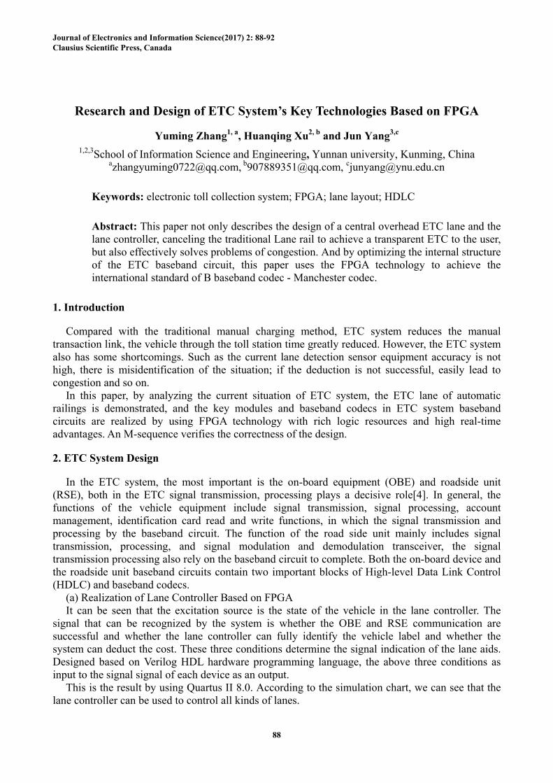
This is the result by using Quartus II 8.0. According to the simulation chart, we can see that the lane controller can be used to control all kinds of lanes.
88
Journal of Electronics and Information Science(2017) 2: 88-92 Clausius Scientific Press, Canada
3. HDLC D
As a bnon-codingsynchronoutransmissio
(a) HDLAccordi
structure, cthe sender Serial and and generaafter the traof the send
(b) ImplSince th
the state mneed for Hdescribes t
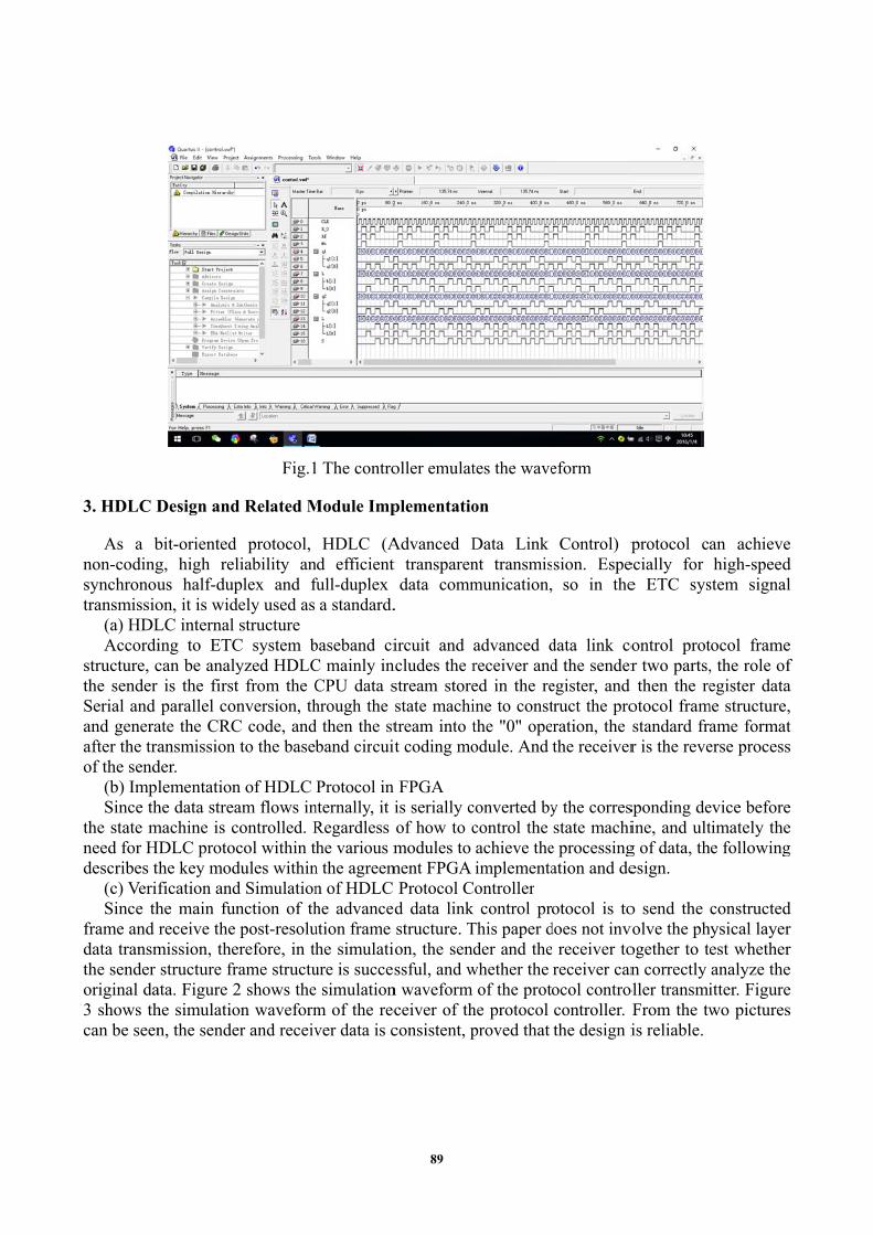
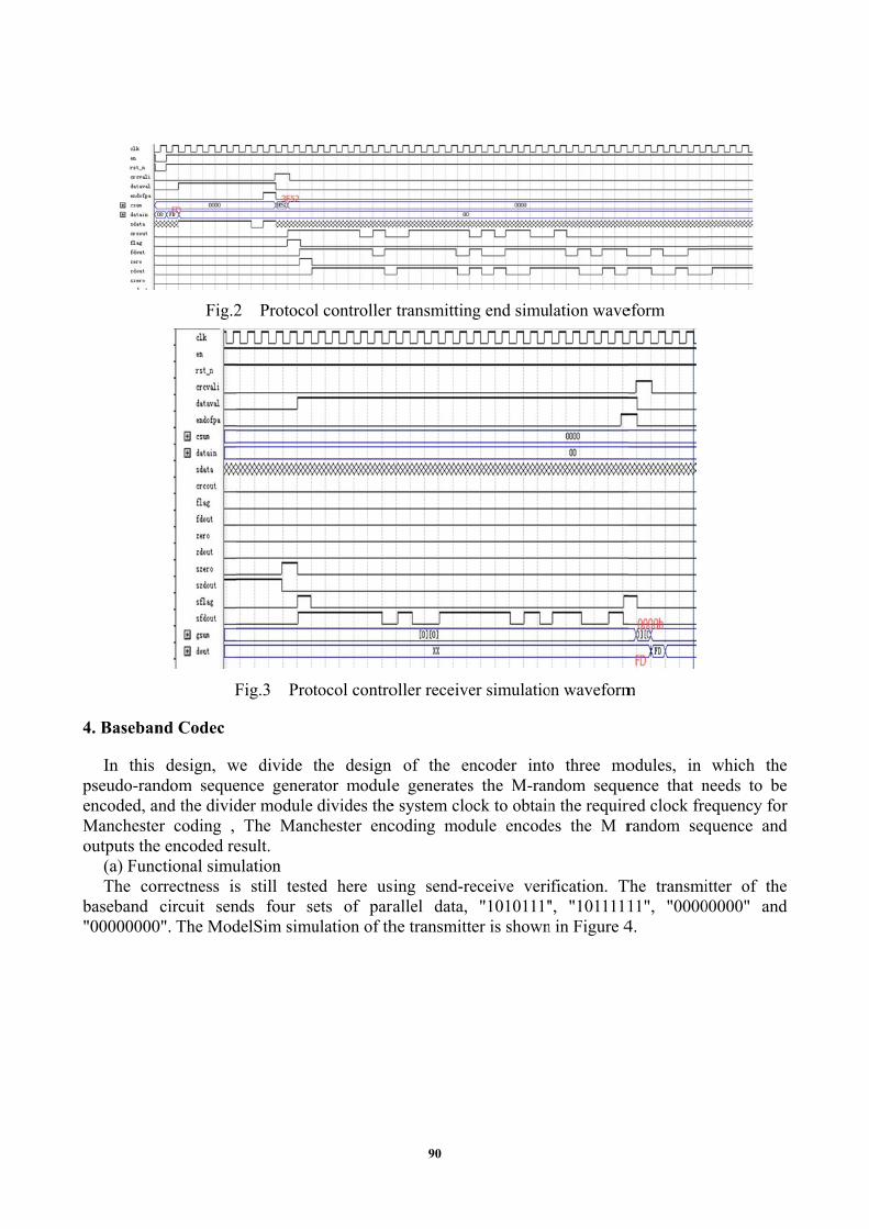
(c) VerifSince th
frame and data transmthe sender original da3 shows thcan be seen
Design and
bit-oriented g, high relus half-dupon, it is widLC internal ing to ETCcan be analy
is the firstparallel con
ate the CRCansmission
der. lementation
he data streamachine is cHDLC protocthe key modfication andhe main funreceive the
mission, thestructure fr
ata. Figure 2he simulation, the sende
Fig.1
d Related M
protocol, liability anplex and f
dely used as structure
C system byzed HDLCt from the Cnversion, th
C code, andto the baseb
n of HDLC am flows incontrolled. Rcol within tdules withind Simulationnction of thpost-resolu
erefore, in thrame structu2 shows theon waveformer and receiv
1 The contro
Module Imp
HDLC (And efficient full-duplex
a standard.
baseband ciC mainly inCPU data shrough the d then the stband circuit
Protocol in nternally, it iRegardless he various m
n the agreemn of HDLC he advancedution frame he simulatioure is succese simulationm of the recver data is c
oller emulat
plementatio
Advanced Dt transparen
data comm.
ircuit and ncludes the rstream storestate machitream into tt coding mo
FPGA is serially cof how to cmodules to
ment FPGA Protocol Cd data linkstructure. Ton, the sendssful, and w
n waveform ceiver of thconsistent, p
tes the wave
on
Data Link nt transmismunication,
advanced dreceiver anded in the reine to constthe "0" opeodule. And
converted bycontrol the achieve theimplementa
Controller k control prThis paper dder and the
whether the of the proto
he protocol proved that
eform
Control) psion. Espe
so in the
data link cod the senderegister, and truct the proration, the the receiver
y the corresstate machi
e processingation and de
otocol is todoes not inv receiver toreceiver canocol controcontroller. the design i
protocol caecially for e ETC sys
ontrol protr two parts,then the re
otocol framstandard frar is the reve
sponding deine, and ultg of data, thesign.
o send the volve the phogether to ten correctly
oller transmiFrom the twis reliable.
an achievehigh-speed
stem signal
tocol frame, the role ofegister data
me structure,ame formaterse process
evice beforetimately thee following
constructedysical layerest whetheranalyze theitter. Figurewo pictures
e d l
e f a , t s
e e g
d r r e e s
89
4. Baseban
In this pseudo-ranencoded, aManchesteoutputs the
(a) FuncThe co
baseband "00000000
Fig.2
F
nd Codec
design, wndom sequeand the divider coding , e encoded rectional simurrectness iscircuit sen
0". The Mod
2 Protoco
Fig.3 Prot
we divide tence generader module
The Mancesult. ulation s still testends four sedelSim simu
l controller
tocol contro
the design ator moduledivides the
chester enc
ed here usets of paraulation of th
transmittin
oller receive
of the ene generates
e system clocoding mod
ing send-reallel data, he transmitt
ng end simul
er simulatio
ncoder intos the M-ranock to obtaindule encode
eceive veri"1010111"
ter is shown
lation wave
on waveform
o three mondom sequen the requires the M r
fication. T", "1011111n in Figure 4
eform
m
odules, in ence that nred clock frerandom seq
The transmi11", "00004.
which theneeds to beequency forquence and
itter of the00000" and
e e r d
e d
90
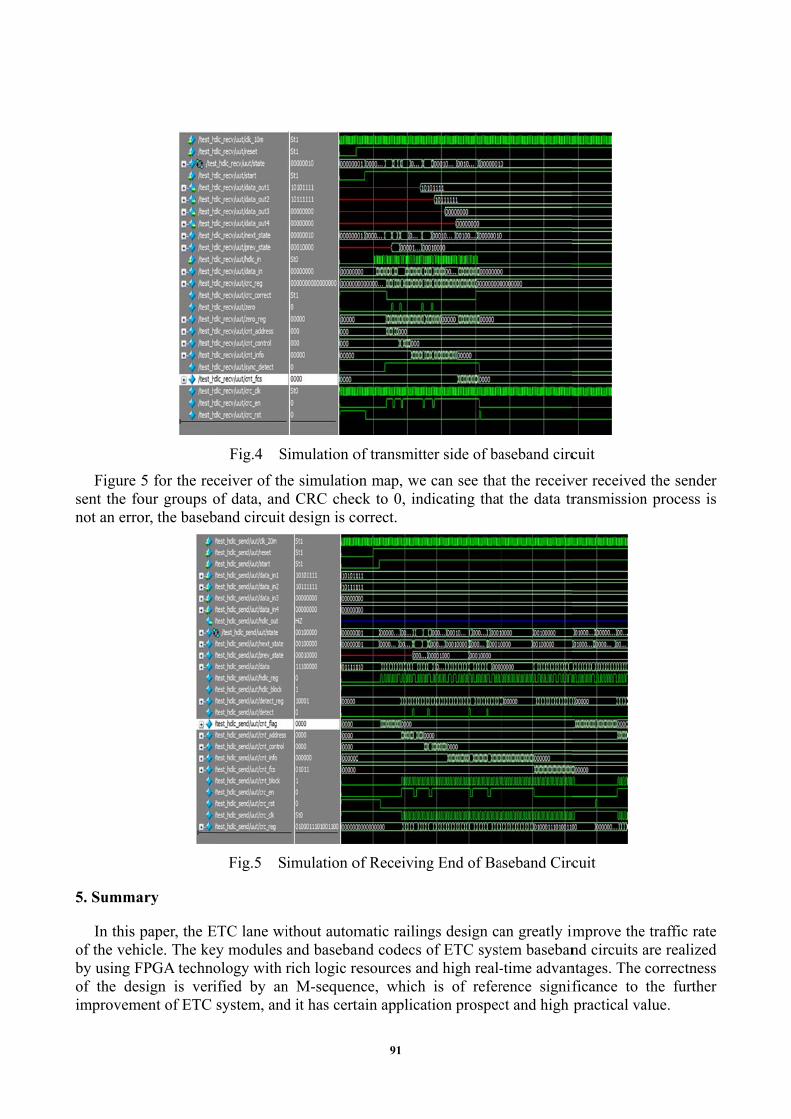
Figure 5sent the fonot an erro
5. Summa
In this pof the vehiby using Fof the desimproveme
5 for the recour groups oor, the baseb
ary
paper, the Eicle. The kePGA techno
sign is verient of ETC
Fig.4 S
ceiver of thof data, andband circuit
Fig.5 S
ETC lane wiey modules ology with ified by ansystem, and
Simulation o
he simulatiod CRC checdesign is co
imulation o
ithout automand basebanrich logic re
n M-sequend it has cert
of transmitte
on map, we ck to 0, indorrect.
of Receiving
matic railingand codecs oesources annce, which tain applicat
er side of ba
can see thadicating that
g End of Ba
gs design caof ETC systnd high real-
is of refertion prospec
aseband circ
at the receivt the data tr
aseband Circ
an greatly imtem baseban-time advanrence signifct and high
cuit
ver receivedransmission
cuit
improve thend circuits antages. The ficance to practical va
d the sendern process is
e traffic rateare realizedcorrectnessthe further
alue.
r s
e d s r
91
References
[1] Ishikawa, Toru.”New advances in Electronic Toll Collection (ETC) systems” [C].15th World Congress onIntelligent Transport Systems and ITS America Annual Meeting, 2008.
[2] Marco Amorim, António Lobo.Optimal location of electronic toll gantries: The case of a Portuguese freeway[C].Procedia-Social and Behavioral Sciences 111 ( 2014 ) 880-889,2014.
[3] Nowacki, Gabriel, Niedzicka, Anna.Polish Research on the Subject of Electronic Toll Collection [C].Warsaw,Poland, Motor Transport Institute, Jagiellonska 80, 03-301, 2011.
[4] Analyzing Performance of ETC Plazas Using New Computer Software.Comp.in Civ.Engrg,2001,15(4):309-319.
[5] Yan T. The Development of ETC and its Problems[J]. Radio Frequency Identification Technologies &Applications, 2009.
[6] Yao W Q, Zhou W. Design of FM0 decoder in ETC[J]. Electronic Design Engineering, 2011.
[7] Sánchez S, Criado R, Vega C. A generator of pseudo-random numbers sequences with a very long period[J].Mathematical & Computer Modelling, 2005, 42(7-8): 809-816.
[8] Wang D, Song X, Zhu S, et al. The Experimental System of GNSS-based ETC Applied in China[J]. Lab on AChip, 2012, 12(3): 464-473.
[9] Wang-Cheng H U. Design and Implementation of Contactless IC Card in the ETC System for NationalStandard[J]. Microcomputer Information, 2009, 366(1):114–121.
92


![The Solar System’s Motion in the Galactic Tidal Field 597[3].pdfThe Solar System’s Motion in the Galactic Tidal Field ... parameters for the solar system’s motion were taken](https://img.pdfslide.us/doc/110x75/5ab63e5c7f8b9a1a048d9cc1/the-solar-systems-motion-in-the-galactic-tidal-field-5973pdfthe-solar-systems.jpg)

![A Low Distortion Image Defogging Method Based on Histogram ...clausiuspress.com/assets/default/article/2020/06/... · 6/8/2020 · algorithm proposed by Kim et al. [6], the contrast](https://img.pdfslide.us/doc/110x75/60221f26ab57d25476410622/a-low-distortion-image-defogging-method-based-on-histogram-682020-algorithm.jpg)

![An IMA Static Load Balancing Strategy Optimization …clausiuspress.com/assets/default/article/2017/01/07/...2017/01/07 · [4] Tarek Helmy, Hamdi Al-Jamimi, Bashar Ahmed, Hamzah](https://img.pdfslide.us/doc/110x75/5fcb1b9b42a2c207276f2688/an-ima-static-load-balancing-strategy-optimization-20170107-4-tarek-helmy.jpg)