Embed Size (px)
Citation preview

Research and Application of the Cutter Geometry On-Machine Measurement Using Laser Tool Setters
Zixi Fang
A Thesis
In the Department
of
Mechanical and Industrial Engineering
Presented in Partial Fulfillment of the Requirements
For the Degree of Master of Applied Science at
Concordia University
Montreal, Quebec, Canada
February 2015
© Zixi Fang, 2015

CONCORDIA UNIVERSITY
School of Graduate Studies
This is to certify that the thesis prepared
By: Zixi Fang_________________________________________________________
Entitled: Research and Application of the Cutter Geometry On-Machine Measurement using Laser Tool Setter
and submitted in partial fulfillment of the requirements for the degree of
Master of Applied Science (Mechanical Engineering)
complies with the regulations of the University and meets the accepted standards with respect to
originality and quality.
Signed by the final examining committee:
Dr. S. Narayanswamy Chair
Dr. L. Wang Examiner
Dr. Y. Zhang Examiner
Dr. Z. C. Chen Supervisor
Approved by ________________________________________________________
Chair of Department or Graduate Program Director
________________________________
Dean of Faculty
Date ________________________________

iii
ABSTRACT
Research and Application of On-Machine Measurement with Laser Tool Setter
Zixi Fang
This thesis mainly focuses on the study and application of the integration of Computer
numerical control (CNC) machining and on-machine cutting tool measurement. According to the
industry survey, in current aerospace industry, the usage of off-line tool setters is one of the most
prevailing ways for cutting tools measurement. The following up manual tool data input is
required so that the CNC machine will know the tool dimension and finish the assigned machining
tasks. Off-line tool setters are often of high accuracy and the measurement results are reliable.
However, due to its off-line characteristic, after the tool is used, its current dimension status
cannot be known or updated. Thus the quality of the upcoming machined parts cannot be
guaranteed. Moreover, the involvement of operators’ manual data input in the traditional
method inevitably introduces human error to machining from time to time.
To improve the process of part machining and eventually achieve produced parts that are
within tolerance, a new approach is proposed in this thesis on the integration of machining and
on-line tool measurement. The idea is to perform tool measurement without unloading the tool
from the CNC machine, and update the tool dimension data in the machine control before the
tool is used to machine the part. The key to this approach is the employment of a laser tool setter,
an optoelectronic device that has the ability to communicate with the CNC control. Analysis on
kinematics of this new type of device is conducted and its method of communication with CNC
machine control is described.
Special software on CNC machine control level must be utilized to achieve the objective of
on-machine measurement. Custom macros features of FANUC controls is used to suit the needs
of parametric programming. The discussions on custom macros feature are carried out in this
thesis. With the measurement method established, measurement uncertainty of the system will
be discussed in depth. Considering the special attributes of the laser tool setter, the tool geometry
and the machine control, an optimized measurement strategy is studied and proposed.

iv
Finally, experiments are carried out to verify the accuracy and repeatability of the
measurement system. Application on rejecting out-of-tolerance tool being used in machining is
also discussed. The result of applications shows the measurement system is suitable for industry
use.

v
ACKNOWLEDGEMENTS
I hereby wish to express my sincerest gratitude and appreciation to my supervisor,
Dr.Chevy Chen, for his priceless guidance and insights that lead me through this research. His
meticulous attitude toward engineering research would keep on propelling me in my future life.
He is also a role model in my life, showing me how to be responsible, dedicated and intelligent
person.
I would also like to thank my fellows in our lab for their generous support and ideas when
I encountered problems.
Finally, I give my special thanks to my parents for their unselfish love, my good friend,
Laura E. Hilderley, for her encouragement in the past two years.
vi
Table of Contents
List of Figures ....................................................................................................................... ix
List of Tables ........................................................................................................................ xi
CHAPTER 1 INTRODUCTION ................................................................................................... 1
1.1 Background ....................................................................................................................... 1
1.2 On-machine Measurement Techniques ........................................................................... 2
1.2.1 On-machine Measurement with Touch Probe .......................................................... 2
1.2.2 On-machine Measurement with Tool Setter ............................................................. 2
1.2.3 Communication between Tool Setters and CNC Machine Controls .......................... 3
1.3 Literature Review ............................................................................................................. 4
1.4 Research Objective ........................................................................................................... 5
1.5 Thesis Outline ................................................................................................................... 6
CHAPTER 2 ON-MACHINE MEASUREMENT SYSTEM WITH LASER TOOL SETTER ....................... 7
2.1 Introduction...................................................................................................................... 7
2.2 On-Machine Tool Measurement System Structure ......................................................... 7
2.3 Tool Setter Device ............................................................................................................ 9
2.3.1 Introduction to Tool Setter Device ............................................................................ 9
2.3.2 Structure of Laser Tool Setter ................................................................................. 10
2.3.3 Conical Laser Tool Setter ......................................................................................... 11
2.3.4 Parallel Laser Tool Setter ........................................................................................ 12
2.3.5 Protection for the Tool Setter.................................................................................. 13
2.4 Interface Unit ................................................................................................................. 15
2.5 CNC Systems ................................................................................................................... 16
2.5.1 The Construction of CNC Systems ........................................................................... 16
2.5.2 MMI Function .......................................................................................................... 18
2.5.3 CNC Function ........................................................................................................... 20
2.5.4 PMC Function .......................................................................................................... 20
2.5.5 Communication between CNC and PMC ................................................................. 21
2.6 Compatible Measurement Software .............................................................................. 22
CHAPTER 3 FANUC MACRO PROGRAMMING........................................................................ 23

vii
3.1 Introduction.................................................................................................................... 23
3.2 Macro Programming in a Nutshell ................................................................................. 23
3.3 Macro Programming Structure ...................................................................................... 24
3.3.1 Macro Definition ..................................................................................................... 24
3.3.2 Macro Call and Return ............................................................................................ 25
3.3.3 Macro Input............................................................................................................. 26
3.3.4 Macro Body ............................................................................................................. 27
3.3.5 Macro Nesting ......................................................................................................... 27
3.4 Features of Macro Programming ................................................................................... 28
3.4.1 Variables ................................................................................................................. 29
3.4.2 Functions ................................................................................................................. 31
3.4.3 Program Control ...................................................................................................... 34
3.5 Custom Macro and CNC Internal Information ............................................................... 34
3.5.1 Work Offset ............................................................................................................. 35
3.5.2 Tool Offset Memory ................................................................................................ 36
3.5.3 Axis Position ............................................................................................................ 37
3.5.4 Other CNC Functions Associating with System Variable ......................................... 38
CHAPTER 4 MEASUREMENT UNCERTAINTY AND PROBING STRATEGY STUDY ....................... 40
4.1 Introduction.................................................................................................................... 40
4.2 Measurement Support Function .................................................................................... 40
4.2.1 Interface Signals and SKIP Signal ............................................................................ 40
4.2.2 SKIP Function Command (G31) ............................................................................... 42
4.2.3 Application of CNC Measurement Support Functions with Laser Tool Setter ......... 44
4.3 Measurement Uncertainty ............................................................................................. 46
4.3.1 Residual Coolant ..................................................................................................... 46
4.3.2 Alignment Error ....................................................................................................... 47
4.3.3 Trigger Signal Response Delay ................................................................................ 51
4.3.4 Compensation Method ........................................................................................... 54
4.4 Measurement Strategy .................................................................................................. 55
4.4.1 Multi-touch Measurement Strategy ....................................................................... 55
4.4.2 Measurement Cycle Time Calculation ..................................................................... 56
4.5 Measurement Error Analysis .......................................................................................... 66
4.5.1 Flute Trajectories .......................................................................................................... 66
4.5.2 Condition for the Correct Trigger Status ....................................................................... 69
4.5.3 Relation between Feedrate, Spindle Speed and Flute Radius ...................................... 71
4.5.4 Application of the Relation between Spindle Speed, Feedrate and Radius .................. 73

viii
CHAPTER 5 APPLICATION ..................................................................................................... 77
5.1 Introduction.................................................................................................................... 77
5.2 Experiment ..................................................................................................................... 77
5.3 Application with Out-Of-Tolerance Warning Feature .................................................... 79
CHAPTER 6 CONCLUSIONS AND FUTURE WORK ................................................................... 82
6.1 Conclusions..................................................................................................................... 82
6.2 Future work .................................................................................................................... 82
Bibliography ........................................................................................................................ 84
ix
List of Figures
Fig 2.1 On-machine tool measuring system ................................................................................... 8
Fig 2.2 Measurement procedure .................................................................................................... 9
Fig 2.3 The main components of laser tool setter ........................................................................ 10
Fig 2.4 Tool setter with a focal point ............................................................................................ 11
Fig 2.5 Tool setter with a focal point ............................................................................................ 11
Fig 2.6 Tool setter with parallel laser ............................................................................................ 12
Fig 2.7 Tool measurement takes place anywhere along the beam .............................................. 13
Fig 2.8 Tool setter protection mechanism .................................................................................... 14
Fig 2.9 Mini-pin hole equipped on the walls ................................................................................ 15
Fig 2.10 Interface unit ................................................................................................................... 15
Fig 2.11 Machine-Human interface of FANUC control ................................................................. 17
Fig 2.12 FANUC PMC ..................................................................................................................... 17
Fig 2.13 CNC system architecture ................................................................................................. 18
Fig 2.14 Fanuc control panel ......................................................................................................... 19
Fig 2.15 Fanuc operation panel..................................................................................................... 19
Fig 2.16 Communication between CNC, PMC and machine tool ................................................. 21
Fig 3.1 Embedded macro program ............................................................................................... 25
Fig 3.2 Macro nesting and local variables ..................................................................................... 28
Fig 3.3 Work offset registers of a 3-axis milling machine ............................................................. 36
Fig 3.4 System variables corresponding to work offset ................................................................ 36
Fig 4.1 Measurement schematics ................................................................................................. 45
Fig 4.2 Misalignment in Y-axis direction ....................................................................................... 47
Fig 4.3 Misalignment in Z-axis direction ....................................................................................... 48
Fig 4.4 Tool length measurement with radius offset applied ....................................................... 49
Fig 4.5 Measurement error due to Z-axis misalignment 2 ........................................................... 49
Fig 4.6 Time sequence for a tool to trigger the tool setter .......................................................... 51
x
Fig 4.7 Relationship between readout error and feedrate ........................................................... 53
Fig 4.8 Motion sequence of a multi-touch measurement cycle .................................................. 56
Fig 4.9 Radius clearance position .................................................................................................. 57
Fig 4.10 Deceleration ................................................................................................................... 59
Fig 4.11 Measurement cycle motion sequence ........................................................................... 60
Fig 4.12 Velocity profile ............................................................................................................... 62
Fig 4.13 Back-off distance and compensated position ................................................................. 64
Fig 4.14 Trochoidal trajectory ....................................................................................................... 66
Fig 4.15 An end mill with 2 flutes.................................................................................................. 66
Fig 4.16 Flute trajectory for one flute ........................................................................................... 68
Fig 4.17 Relationship between spindle speed and feedrate ........................................................ 71
Fig 4.18 Type 1 boring tool ........................................................................................................... 73
Fig 4.19 Type 2 boring tool ........................................................................................................... 73
Fig 4.20 Beam position .................................................................................................................. 74
Fig 4.21 Unfavorable trigger condition for type 1 boring bar ...................................................... 75
Fig 4.22 Beam position for type 2 boring bar ............................................................................... 75
Fig 4.23 Unfavorable trigger condition for type 2 boring bar ...................................................... 76
Fig 5.1 Measurement with laser tool setter ................................................................................. 79
Fig 5.2 Acceptable range of radius wear input ............................................................................ 80

xi
List of Tables
Table 3.1 Program number range ................................................................................................. 24
Table 3.2 Command for macro call and macro return ................................................................. 26
Table 3.3 Macro call with arguments ........................................................................................... 26
Table 3.4 Relationship between local variables and arguments .................................................. 27
Table 3.5 Variable scopes ............................................................................................................. 29
Table 3.6 Variable declaration ...................................................................................................... 30
Table 3.7 Arithmetic functions summary ..................................................................................... 31
Table 3.8 Examples of the use of arithmetic functions ................................................................ 32
Table 3.9 Trigonometric functions summary ................................................................................ 32
Table 3.10 Logical operation summary ......................................................................................... 32
Table 3.11 Examples of the use of logic operators ....................................................................... 33
Table 3.12 Logical operations summary ....................................................................................... 33
Table 3.13 Program control summary .......................................................................................... 34
Table 3.14 Tool offset registers .................................................................................................... 37
Table 3.15 System variables corresponding to tool offset registers ............................................ 37
Table 3.16 System variables on axis position data ....................................................................... 38
Table 3.17 Other functions and system variables ........................................................................ 39
Table 4.1 Three types of interface signals .................................................................................... 42
Table 4.2 System variable and machine axis values for SKIP ........................................................ 44
Table 4.3 Parameters for measurement cycle time ..................................................................... 65
Table 5.1 Radius measurement results (units: mm) ..................................................................... 78

1
CHAPTER 1 INTRODUCTION
1.1 Background
In modern manufacturing, Computer numerical control (CNC) machining occupies an
important position due to its high accuracy and high efficiency. The rapid development of CNC
machining technology pushes manufacturing industry toward mass production. The integration
of machining and measuring providing a monitoring environment to guarantee the machined
parts accuracy, has also become a mainstream in the modern manufacturing. Electronic sensors
such as on-machine probe and tool setters can be installed and utilized to perform automatic
gauging without unclamping the produced part or unloading the cutting tool, as opposed to
tedious human measurement intervention. In this way, production cycle can be shortened while
machine accuracy can be guaranteed and eventually the ability of manufacturing will be
improved.
Due to its complexities and high quality requirement, parts for aerospace industries are
the best suit for the implementation of on-machine measurement. For expensive aerospace parts,
both quality and production efficiency play a very important role in the industry. The quality of
produced parts directly affects the performance of the assembled products while the efficiency
of production influences the overall manufacturing cycles. Meanwhile, as CNC machining has its
unparalleled advantages in efficiency and accuracy, a broad adaption of CNC machining prevails
in big aerospace companies, in order to suit the high requirement and demand market. These
CNC machined parts have many features such as frames, walls, ribs, pockets, and holes etc.
Besides, relatively larger in part size, these aerospace parts should be machined with longer time
and multiple procedures. However, a high production quantity is also required by the industry.
Machining a part with accuracy and efficiency is the most desirable condition in the aerospace
industry. Hence, the requirements of aerospace parts highly demand the integration of on-
machine measurement techniques while the CNC machining environment in the industry
provides on-machine measurement a favorable and feasible practice environment.

2
This thesis describes an implementation of the on-machine measurement techniques, or
what someone would called closed-door machining, with a laser tool setter. The method helps
expedite the tool setup procedures, prevent initial manual input errors in tool data, update the
tool data during production process, and report the tool excessive wear or breakage at a proper
time.
1.2 On-machine Measurement Techniques
On-machine measurement integrated with traditional CNC machine procedures can also
be called as closed door machining. It is a part-producing strategy using on-machine
measurement devices to automate error adjustment as opposed to manual gauging intervention,
with the aim of achieving within-tolerance parts. In terms of the device being used, on-machine
measurement techniques can be divided into two categories: measure parts with touch probe
and measure cutters with tool setter.
1.2.1 On-machine Measurement with Touch Probe
Throughout the years, many studies on the application of touching probes have been
conducted in order to ensure the part accuracy on the CNC machine. These applications conduct
the measurement on the machine so that procedures of unclamping the machine part and re-
clamping it to the CMM machine can be avoid. They eliminate the often introduced errors such
as: 1) unclamping/re-clamping error. 2) Deformation error due to multiple setups, especially for
some large volume parts with thin walls.
1.2.2 On-machine Measurement with Tool Setter
The importance of applications of tool setters cannot be neglected. To machine a part
accurately, the machine control should know the tool tip position relative to spindle reference

3
point. The up-to-date cutter dimension information is crucial during the procedure of machining,
as cutters wear after used and excessive wear will generate unqualified parts.
The tool setter installed on machine measures the tool data during the part producing
process. The measured data can used in monitoring the current tool condition, ensuring the
cutter’s capability to perform the assigned tasks and thus reducing scrap. Software updates the
tool registers in the machine control with the newest tool data automatically, automating the
compensation of path procedure, improving the part accuracy while avoiding human error
induced by manual offset updates.
In comparison to off-line tool setting, on-machine tool setting with laser tool setter takes
the actual machining environment factors into account. Hence, it compensates the inability of
the off-line tool setting system and yields a better measurement result. The main advantages can
be summarized as the followings: 1) Errors caused by the spindle run-out, the tool holder and the
tool itself can be eliminated as the tool setting procedure takes place while rotating; 2) Thermal
factors and spindle “pull-up” can be take into account; 3) It can rapidly measure the on-machine
tool length, simplifying setup procedure (no manual touch-off for every tool is required).
Tool setter also compensates the inability of part-probing measuring system by obtaining
tool data. Even though the part-probing measuring system reports machined part dimension, due
to the lack of information about the cutters condition, the reasons for some found errors in a
machined part may not be identified.
1.2.3 Communication between Tool Setters and CNC Machine Controls
The on-machine measurement device like tool setter is an electronic sensor and its trigger
signal should be recognized by the CNC control. An interface unit connecting the tool setter and
CNC control is needed. It powers up the tool setter with the 12V output power source of the
machine control. Meanwhile, it also works as a convertor, transforming the tool setter signals
into voltage-free solid-state relay (SSR) outputs and sending to the machine control.

4
To serve the special requirements for the on-machine tool measuring, parametric
programming with a high level CNC programming language is required. This kind of language is
known as Custom Macros, User Macros or just Macros in Fanuc and various compatible controls
such as Fadal and Okuma or Flexible programming in Siemens control. Custom macros offer the
possibilities to perform logic, arithmetic and branching functions similar to other high-level
computer languages like Visual C++, Visual Basic or Tool Command Language. Software with
algorithm can be written with custom macros and installed in the machine control as any other
NC programs. Then by using a certain NC command, such as G65 in FANUC control, the software
will be called to perform its tasks from the machine control level and thereby realize the goal of
on-machine measurement.
1.3 Literature Review
Over the years, a rapid growth of probing technology is seen and on-machine
measurement systems have been put into practice in many fields. Studies have conducted to
prove the accuracy of machining can be improved through on-machine inspection methods [1].
Hollingum and Jack [2] reported that with the help of touch probes, the continuous machining
process can generate an error less than 6 𝜇𝑚. In the other technical papers, the device that can
be used to perform on-machine cutting tool measurement tasks [3-9] are described and
discussed. In 1997, Kurada and Bradley [3] made a summary about computer vision techniques
used in tool condition monitoring. With a different approach involving the cutting tool touching
the tool setter, RB Morrison and PK Hellier [4] purposed a touch-triggered type of tool position
measuring device. Stimpson,Victor G [5] described a new type of tool position detecting device
based on laser technology. After the implementation of laser technology in tool setters, British
company Renishaw has gone further to perfect its measuring ability. Improving algorithms on
processing the signal received from the laser tool setter had been discussed by Stimpson,Victor
G [6] in 2005, Merrifield, Benjamin J [7] in 2007 and Egglestone, Edward Benjamin [8] in 2013.
Meanwhile in 2004, Hyeon-Hwa Lee and Min-Yan Yang [9] described a three dimensional tool

5
measurement system based on optical sensors, enabling a more detailed tool data measurement
result.
With the tool setter technology available, it is important to apply it to the industry. M
Lynch studied measurement error and calibration method for the workpiece probe and method
to develop probing software using FANUC custom macro in his book [10]. These give significant
insights for the later software development for tool setters. In 2001, Huang [11] carried out a
study on the application of the touch-trigger tool setter based on FANUC custom macro. A
different approach on facilitating the tool setter with NC machine was conducted in 2005 by
Huang, Jiyong [12]. In his master thesis, a method based on PLC ladder diagram programming is
proposed. Experiments comparing two types of laser tool setter had been carried out by Lee,
Eung Suk & Sung Chung Kim [13] in 2008, demonstrating that the laser tool setter fits the
requirement of industry.
To further understand the feature of measurement system, measurement error and
measurement method must be addressed. Renishaw conducted surveys [14-15] on
measurement uncertainty due to machine response time and measurement system geometry.
These surveys give a preliminary understanding for the world about the tool probing technology.
In order to further improve the performance of the measurement system, optimal measurement
cycles are necessary. Although there is a lack of deep discussion on measurement strategy with
laser tool setter, an optimal measurement strategy for workpiece probing has been addressed
by Renishaw [16].
This thesis hence studies the measurement uncertainty and the optimized probing
strategy for the laser tool setter.
1.4 Research Objective
The objectives of this thesis focus on proposing a better integration of laser tool setter
and CNC machine and the work can be concluded by the following aspects:

6
Components of on-machine measurement system and their intercommunication are
studied.
A high level CNC programming language that is key to the development of the
measurement software is reviewed.
To better understand laser tool setters and to develop an optimized probing strategy,
measurement errors and measurement cycle time analysis are carried out.
Applications and experiments are also presented to prove the stability and reliability of
the on-machine measurement system.
1.5 Thesis Outline
This thesis consists of six chapters. CHAPTER 1 gives a general introduction about the on-
machine measurement system. Reviewed literatures on this topic are also presented. CHAPTER
2 dissects the components and technology used for the laser tool setter and its interface with
CNC machine. Structure of CNC system is also described in details in order to establish a solid
ground for the following up research. CHAPTER 3 focuses on the essence of the high level CNC
programming language, FANUC custom macros, which are necessary for the measurement
software development. CHAPTER 4 studies the communication between the laser tool setter and
CNC machine. An in-depth examination is carried out on laser tool setter’s characteristics and the
measurement error that lead into the measurement results. In order to find out an optimized
measurement strategy, measurement cycle time is also considered with CNC machine features.
CHAPTER 5 presents the application of the integration of the laser tool setter and CNC machine
to prove the reliability of the system. CHAPTER 6 concludes the work of the employment of on-
machine measurement system and proposes the possible future work.

7
CHAPTER 2 ON-MACHINE MEASUREMENT SYSTEM WITH
LASER TOOL SETTER
2.1 Introduction
Both hardware and software are required to support the on-machine tool measuring
system. The system consists of a tool setter as the measuring device, an interface unit as the
communication device and special NC programs as the software to drive the tool measuring
movement.
This chapter describes the structure of the system. Hardware components of the on-
machine tool setting system are also discussed in-depth. Software components are mentioned
but not in depth as they employ algorithms depicted in the following chapters.
2.2 On-Machine Tool Measurement System Structure
The on-machine tool measurement system is constructed by three parts: a tool setter
system, an interface unit and a CNC control, as can be seen from Fig 2.1.

8
Each component has its own functions: 1) Tool setter system is a mechatronic device
equipped with sensors that transform the physical movement into digital signal; Circuits to
preform pre-built algorithms functioning signal acquisition and signal processing is also included
in tool setter; 2) Interface unit is a PLC that converts the receiving signal to solid state relays
output for CNC control; 3) CNC control provides parametric programming environment for the
development of the special tool setting software. The software is run according the commands
given by the programmer. Machine tool is then controlled to perform measuring tasks, involving
triggering the tool setter. With the received output signal passed by the interface unit, software
also does the calculation and eventually updates the tool offsets or reports tool conditions. The
working system proceeds as a close-loop system and the procedures are as shown in Fig 2.2 .
Interface Unit
Machine Control
Tool Setter
Fig 2.2-1 on-machine tool measuring system Fig 2.1 On-machine tool measuring system

9
Fig 2.2 Measurement procedure
2.3 Tool Setter Device
2.3.1 Introduction to Tool Setter Device
Currently, methodology for on-machine measurement can be divided into two categories:
touch-trigger measurement and non-contact measurement, or in common used terms, “contact”
and “non-contact”. Both methods are employed in the in-market tool setter. Contact-triggered
is the signal-output method based on pressure-electronic sensors, which monitor the change in
electrical resistance due to the displacement of the tool setter hardware. Contact-triggered
method has high repeatability and accuracy and has been used for decades by the industry.
Whereas, non-contact triggered method is developed, based on modern optical science.
Technology such as infrared wave, digital photos (machine vision), and laser have been applied
to realize the purpose of goal of non-contact measuring. However, due to the instability of the
vision system imaging quality and limitation of CCD camera resolution or image acquisition ability,
vision based non-contact measuring system suffers from lower accuracy. Laser technology, on
the other hand, overcomes the imperfection of vision based systems and is often applied with
non-contact tool setters. Laser technology uses optical-electronic devices as the signal-output
source. Tool setters integrated with laser technology equip advantages of having shorter
response time while not losing accuracy. Compared to contact-trigger tool setters, its non-

10
contact feature expedites the procedure of measurement as the tool can move toward the laser
at a higher speed without damaging the tool setter. Therefore, the system discussed in this thesis
is based on the use of non-contact laser tool setter.
2.3.2 Structure of Laser Tool Setter
Laser tool setter device works on the optoelectronic science basis. The main components
consist of a laser transmitter and an optical receiver, as can be seen from Fig 2.3. When the cutter
moves into the laser region, part of the laser is blocked and when the light reduction exceeds a
certain level the tool setter will trigger.
Transmitter
Reciever
Laser
Laser Tool Setter
Cutter
Fig 2.3 The main components of laser tool setter

11
2.3.3 Conical Laser Tool Setter
A conical laser tool setter uses conical-shaped laser beam to perform measuring task. It is
the first generation of tool setter. A more detailed illustration of this type of tool setter can be
seen from Fig 2.4. The laser diode in the transmitter emits the laser through the lens to form a
conical set of laser which converges into a focus point between the transmitter and receiver.
On the focal point, the beam has narrowed to a small size that can be used to measure
small tools, as can be seen from Fig 2.5.
Fig 2.4 Tool setter with a focal point
Fig 2.5 Tool setter with a focal point

12
The focal point for small tool measurement is crucial because the small tool may not be
able to block sufficient laser elsewhere in the laser beam set to generate the trigger signal.
However, this small tool measuring ability weakens as the separation of the transmitter and
receiver grows. The farther the distance is, the less convergent the laser becomes. When
measuring happens and in the same measuring position, the small tool does not block as much
light in a less convergent situation as in a higher convergent situation. This yields the loss in
sensitivity of the tool setter. Therefore, most of the conical laser tool setters are built with a
compact design to ensure the measurement accuracy, which also limits the maximum
measurable tool size. Conical laser tool setter also relies highly on alignment of the transmitter
and the receiver, as the light gathered by the receiver will directly affect the measuring result.
2.3.4 Parallel Laser Tool Setter
To overcome the drawback of conical laser tool setters, the parallel laser is utilized. A
more detailed illustration of this type of tool setters can be seen from Fig 2.6.
As illustrated by the figure above, the laser diode emits laser and the lens, which regulate
the laser into a set of rather parallel laser. In addition, in order to diminish the effect of
divergence of the laser beam, a set of two mini-pin holes are featured in proper positions, both
on the transmitter and the receiver unit. The relatively parallel laser beam is further constrained
Fig 2.6 Tool setter with parallel laser

13
by this set of small apertures. Therefore, only a small subset of the original, highly divergent laser
is emerged but this subset is the strongest and most parallel set of laser. There, a set of strong,
small shaped, highly parallel and slightly divergent laser is generated.
With the parallel laser beam, tool measurement can happen in anywhere along the beam
between the transmitter unit and receiver unit (provided the tool does not collide with the tool
setter), as shown in Fig 2.7.
Since the parallel laser beam that comes out from the small aperture is highly convergent,
strong and small in shape, when measuring a small tool, the small tool causes the same amount
of light reduction. This equips the system with a better capability to measure small tools. In
addition, as there is no longer the requirements of measuring a tool on laser focal point, the tool
setter alignment also becomes easier which shortens setup cycle time.
2.3.5 Protection for the Tool Setter
Laser tool setter performs on-machine tool measurement and hence, it often works in
unfavorable conditions. Coolant spraying off from the tool or any other dripping from the
Fig 2.7 Tool measurement takes place anywhere along the beam

14
machine tool should never enter the tool setter unit. With the mini-pin holes featured on both
transmitter and receiver unit, the tool setter is protected at a certain level. To further guarantee
the tool setter protection, high pressure air is supplied within both the transmitter and receiver,
as can be seen Fig 2.8.
High Pressure Air In
High Pressure Air Out
Transmitter Unit Equipped With High Pressure Air Protection
Fig 2.8 Tool setter protection mechanism
The figure above shows schematic for the tool setter protection mechanism. Continuous
air stream is plumped into the transmitter and receiver unit to form positive pressure air steam
so that the protection is available at all time. Meanwhile the mini-pin hole featured on the wall
of transmitter unit also helps to guarantee the high air speed during its emergent process. Up to
250m/s can be reached for the air speed. With this feature, coolant mist near the transmitter or
receiver will be blown away and thus it has no chance to condense or to block the laser.
What is worth noticing is that, the air flow may generate turbulence that will affect the
laser beam condensation and consequently impinge the measurement results. In order to avoid
this unfavorable situation, the mini-pin holes on the transmitter and receiver are setup with an
angle. This way, the angled mini-pin holes will guide the air to a direction that is not parallel to

15
the laser beam and thus the turbulence will not form in the direction of the laser beam, as shown
in Fig 2.9.
Mini-pin hole
Laser beam
Air direction
Transmitter wall
Fig 2.9 Mini-pin hole equipped on the walls
2.4 Interface Unit
Besides from the tool setter device above, a device working as the bridge connecting the
tool setter side and machine control side is also needed. This device is called interface unit, as
shown in Fig 2.10.
Fig 2.10 Interface unit

16
The interface unit converts trigger signal sent by the tool setter device into solid-state
relay (SSR) output. Solid-state relay is an electronic switching device. Unlike the mechanical relays,
which has actual mechanical action such as, turning coolant on/off, performing tool change etc.,
solid-state relay is voltage free and has no mechanical moving parts. This is the kind of relay signal
that FANUC control and majority of controls use to communicate with external devices. The
essence of this type of relay is semiconductor materials.
In addition, the interface also powers up the tool setter device by drawing power from
the machine control side. Through the interface, the normal current and voltage 120mA at 12Vdc
or 70mA at 24Vdc will be provided to the tool setter device.
2.5 CNC Systems
2.5.1 The Construction of CNC Systems
A CNC system comprises three units: NC unit which works as the “brain” of the CNC
system by providing human-machine interface and carrying out position control, the motor unit,
and the driver unit. In the scope of control, NC unit alone is referred to as the CNC control.
In the sense of different functions, the NC unit is composed by MMI (Man-machine
interface), NCK (Numerical Control Kernel) and PLC. In the FANUC’s system, the NCK and PLC are
referred to as CNC and PMC, respectively. Though difference can be seen in naming, they are
referring to the same thing. MMI (man-machine interface) enables the communication between
the end user and the CNC. It supports machine operation commands, current machine status
display. Part programs input and editing are also done within this unit. CNC is the dedicated
computer that interprets part programs, applies interpolation algorithm, position control and
error compensation. Servo system of the CNC machine tool is controlled by CNC. It is the most
important unit of CNC system. PLC (programmable logic control) performs overall machine
control, such as tool change, spindle speed and in/out signal processing except for servo control.

17
Fig 2.11 Machine-Human interface of FANUC control
Fig 2.12 FANUC PMC

18
The architecture of the CNC system can be described by the schematic diagram below.
Information is input by user through MMI. These information will be scanned, and
executed either by CNC or PMC. Feedback from CNC and PMC of their current status will be
available and sent back to MMI for display. Meanwhile, CNC and PMC exchange their status
information. Communication between CNC and PMC is very necessary, for example, when the
part program requires general machine operations such as tool change, spindle rotation and
coolant on/off etc. These operations will be executed by PMC and when the operations have
completed, PMC sends signals to prompt the CNC to start executing the next command of the
part program.
2.5.2 MMI Function
The MMI unit in CNC machine usually consists of two parts, control panel and operation
panel. Control panel consists display screen and soft keys, selection keys, address and numeric
keyboard, and reset key etc. Fig 2.14 shows the layout of a typical control panel. Operation panel
MMI (Man Machine
Interface)
NCK/CNC(Numerical Control
Kernel)
PLC/PMC(Programmable Logic
Control)
Servo System Machine I/O
Human
Fig 2.13 CNC system architecture

19
consists main buttons and switches, status indicator lights, ON/OFF switches (option stop on/off,
single block on/off, coolant function on/off, etc.), Rotary switches (Select mode, feedrate
override, spindle override, etc.), setup handle, etc. Fig 2.15 shows the layout of a typical
operation panel.
Fig 2.14 Fanuc control panel
Fig 2.15 Fanuc operation panel

20
Control and operation panels provide the availability for user to realize the following
functions:
Operation functions, such as feed override, spindle override, MDI…
System parameter-setting
Program-editing
Machine status monitoring and alarm message display
2.5.3 CNC Function
CNC interprets part programs and performs position calculation. Its main components
include interpreter, interpolator, acceleration/deceleration controller and position controller [18]
Interpreter reads the part program and stores data in internal memory. With the help of
buffer, this can be proceeded very quickly. Interpolator calculates the position and velocity for
the machine by using the interpreted data. Position controller uses the interpolated data to
control the servo and motor in order to drive the machine to a certain position.
Acceleration/deceleration controller is introduced to calculate the acceleration/deceleration for
the machine to reach a certain speed in order to prevent vibration and shock.
2.5.4 PMC Function
PMC is responsible for general machine control, except for the axis positioning. PMC
system possesses abilities to perform logic, sequencing, timing, counting or arithmetic calculation.
PMC system in CNC machine is a software-based control system so it has advantages in flexibility
and economic efficiency and due to its programmable characteristic, some advanced control
tasks can be accomplished. Pre-written sequence programmed are compiled and stored in PMC.
The program executes from the beginning of the ladder diagram to the end and then the
procedure repeats. The execution time from the beginning to the end is called a scan. This scan

21
time can be set through a system parameter. The default setting for a FANUC 0i-MC control is 8
msec.
PMC has the following functions when applied to CNC machine tool:
Sends operation status from MMI to CNC and displays CNC status to user via MMI
Information of the change of operation mode (e.g. MDI, Reference, Edit) made by
operator through operation panel is sent to CNC by PMC
JOG, cycle start, feedhold, emergency stop are done through PMC
Though the communication with CNC, PMC helps with the part program execution by
executes M-, T-, S- codes.
Receives and in some cases, processes input signals from external equipment.
2.5.5 Communication between CNC and PMC
In CNC control system, communication between CNC and PMC is of great importance. In
FANUC control, four designated addresses are used to signify the input/output signal for PMC
side and CNC side. These two way communication between machine tool and PMC; PMC and
CNC are described [17] by Fig 2.16.
CNC PMC Machine Tool
G000~
F000~
X000~
Y000~
Fig 2.16 Communication between CNC, PMC and machine tool

22
CNC does not communicate with external devices connected to the machine tool directly.
PMC is the medium between CNC and external devices.
Between the PMC and CNC, F- signal is used for input signal from CNC to PMC while G-
signal is used for PMC output to CNC. Between the PMC and machine tool side, X- signal is used
for input signal from external devices to PMC while Y- signal is used for PMC output to external
devices.
2.6 Compatible Measurement Software
Compatible software written in Custom Macros should be used to practise on-machine
measurement with laser tool setter. In fact, due to the sophistication and difference in tool
geometry data, it would be impossible to program just by using low level G-code language.
Nowadays, some of the newest controls (Sinumerik 840d or some Haas controls) offer measuring
can-cycles (manufacturer-developed measuring software) to perform the measuring task.
However, for the most prevailing FANUC 0i control, these measuring can-cycles are not available.
Therefore, development of these NC programs is required. The following chapter will be
concentrating on Fanuc Custom Macro Programming.

23
CHAPTER 3 FANUC MACRO PROGRAMMING
3.1 Introduction
To achieve the goal of on-machine programming, compatible software should be
developed and installed on the machine control level. High-level CNC programming technique,
typically known as Custom Macros in Fanuc control is essential for this type of software
development. This chapter is dedicated to discussing this type of programming technique and its
application.
3.2 Macro Programming in a Nutshell
Although over the years, formidable improvement in capability and flexibility of the CNC
machine tools and their controls have been seen, macro programming techniques have not yet
drawn much attention. The reasons for it to be under-publicized could be: 1) in the age where
CAM software prevails and automates the programming process, most of complicated machining
tasks can be accomplished by the only utilization of low-level language such as G-code, M-code…
2) originally, macro programming instructions are not intended for the CNC users rather, for the
machine tool builders to interface the machine control to accessory device [19]. Therefore,
reference materials are rather rare.
However, these high-level instructions featured in CNC control possess the powerful
arithmetic abilities and high flexibility resembling to high-level programming languages such as
Visual C++, Basic or PASCAL in computer programming and should not in any extent be under-
addressed. Custom macros make the parametric programming on machine control level possible.
In addition, by using custom macros, internal information of the CNC control can be attained and
thus the back-staged communication between NC program and CNC control can be accessed and
as a result, program development is granted with more information.

24
For tool setting software development, the ability to parametrically program and the
knowledge of the system internal information such as current part zero offset, current machine
position etc. are of extreme importance. There is no command in low-level G-code language
being able to perform tasks, for example, to attain the current position in Z-axis once the tool
setter is triggered or calculate the difference in X-axis between two positions.
In all, custom macros are a special set of high-level CNC control instructions, mainly used
for realizing special requirements. They possess features resemble to computer programming
languages while also integrate CNC machine related features.
3.3 Macro Programming Structure
A macro is similar to a subprogram but more sophisticated. It can be thought as the
equivalent to “function” in BASIC or C++.
3.3.1 Macro Definition
A macro should be defined before used. A program number should be assigned to a macro
program. Later by using this program number, the corresponding macro can be called,
resembling calling a function by its name in BASIC or C++. These program number must be integer
following a capital letter “O” and must be within the acceptable range of FANUC control. Table
3.1 shows the program number range [20] for FANUC 0i control. Note that the numbers have
been categorized into four groups based on their conventional usage.
Table 3.1 Program number range
Program Number Range Description
O0001 to O7999 Standard program numbers, mostly used for main programs
O8000 to O8999 Group 1 Macro program numbers
O9000 to O9049 Group 2 Macro program numbers with special function
25
(Can use G,M,S and T function to call the macro, instead of using a program number)
O9050 to O9999 Group 2 Macro program numbers
3.3.2 Macro Call and Return
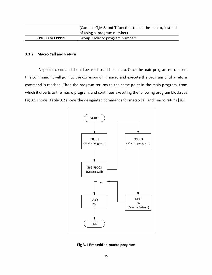
A specific command should be used to call the macro. Once the main program encounters
this command, it will go into the corresponding macro and execute the program until a return
command is reached. Then the program returns to the same point in the main program, from
which it diverts to the macro program, and continues executing the following program blocks, as
Fig 3.1 shows. Table 3.2 shows the designated commands for macro call and macro return [20].
START
O0001(Main program)
G65 P9003(Macro Call)
O9003(Macro program)
M99%
(Macro Return)
M30%
END
…..
Fig 3.1 Embedded macro program

26
Table 3.2 Command for macro call and macro return
Command Syntax Description
G65 P---- Macro call command. After the address “P” follows the program number for the macro (“O” in the program number is not needed).
M99 Macro return command. This command resides in the macro program. Every macro program should end with M99
3.3.3 Macro Input
Data can be input to the macro program as the values on which the macro program
calculation is based. This type of data is called macro arguments. They are defined with macro
call command. Syntax is shown in the following table.
Table 3.3 Macro call with arguments
Command Syntax Description
G65 P---- <Arguments> Macro call command with arguments.
Arguments are input to the macro program by writing the desired values following special
capital letters. For example, the following syntax defines 10.5, 9 and 5 as the values for argument
A, B and C.
𝐺65 𝑃8003 𝐴10.5 𝐵9 𝐶5
These values are then passed into the macro body. Inside the macro body, a special set of symbols,
known as local variables, are utilized to reference the input argument values. Local variables and
the capital letters are used in a corresponding way. Table 3.4 shows the relationship between the
local variables and input arguments [20].

27
Table 3.4 Relationship between local variables and arguments
Argument Address
Local Variable
Argument Address
Local Variable
A #1 Q #17 B #2 R #18 C #3 S #19 D #7 T #20 E #8 U #21 F #9 V #22 H #11 W #23 I #4 X #24 J #5 Y #25 K #6 Z #26 M #13
For example, the following syntax is used to call the macro program.
𝐺65 𝑃8006 𝑇14 𝑊10.5
According to Table 3.4, in the macro program O8006, values stored in local variable #20 and #23
will be assigned with 14 and 10.5. Note that, only the addresses given by Table 3.4 can be used to
pass values as input to macro program.
3.3.4 Macro Body
Three types of components make a complete body of a macro program: Variables,
Functions and Logics. Details on these three types of components will be discussed in the
following section.
3.3.5 Macro Nesting
Nesting feature is also available in macro programs, like other computer programming
languages. Nesting means one macro program is called within another macro program. Up to 4-

28
level of nesting is allowed by FANUC control. Fig 3.2 shows the visual representation of the macro
nesting.
Local variables would not be passed from one macro to another, as the figure above
shows. Every macro has its own set of local variable #1~#33. Further description on local variables
is given in the following sections.
3.4 Features of Macro Programming
Macro programming has features just like any other computer programing languages and
employment of these features comprises the macro body.
START
O0001(Main program)
#1=......
#33=...
G65 P8500(Macro Call)
O8500(Macro program)
#1=......
#33=...
M99%
(Macro Return)
M30%
END
M99%
(Macro Return)
M99%
(Macro Return)
M99%
(Macro Return)
O8501(Macro program)
#1=......
#33=...
O8502(Macro program)
#1=......
#33=...
O8503(Macro program)
#1=......
#33=...
G65 P8501(Macro Call)
G65 P8502(Macro Call)
G65 P8503(Macro Call)
….. ….. ….. …..
Fig 3.2 Macro nesting and local variables

29
3.4.1 Variables
Variables are the most distinct feature in macros. Macro programming can also be
thought as parametric programming in CNC programming. The NC program is developed with
combination of G-codes and macro statements. For example, the program may be created to tell
the machine carry the tool to a certain position. The position the machine is about to go to is not
directly programmed to movement command (G00 for instance), but is programmed as a variable
which receives input from the user later. It can also be said that variables are storage units for
changing data. Values can be stored in these storage units and be used during execution of the
program.
1) Variable Type
Variables supported by FANUC controls can be subdivided into four categories, namely,
null variables, local variables, common variables and system variables. FANUC assigns certain
ranges of integer number following the # symbol to its variables. Different ranges of integer
number represents different categories of variable. Table 3.5 sums up the link between variable
categories and integer ranges. The scopes of each type of variables are also given in Table 3.5.
[20].
Table 3.5 Variable scopes
Number range Type Description
From To
#0 Null variable A variable with no value/ A vacant variable
#1 #33 Local variables These are temporary variables are used in a macro
body and cleared when macro exits
#100
#500
#149
#999
Common variables
Global variables
Common variables are still valid when macros exit
but cleared when the machine resets
Global variables are not cleared even when the
machine resets
#1000 … and
up System variables
System variable can read and write CNC internal
data such as tool registers data, current work
offset, etc.

30
2) Variable Declaration and Usage
Just like any other computer programming languages, variables should be declared before
used. The way to declare variables in FANUC macros is by assigning the # symbol before certain
integer, as has been roughly described in the earlier text:
#𝑖 = 𝑎𝑠𝑠𝑖𝑔𝑛𝑒𝑑 𝑣𝑎𝑙𝑢𝑒
Table 3.6 gives some examples of declaring variables:
Table 3.6 Variable declaration
Expression Description
#10 = 1000 Defines a local variable #10 and assigns value 1000 to it.
#103 = 50 Defines a common variable #103, which will retain when macro exits but will be reset when machine resets. Assigns value 50 to it.
#560 = 90 Defines a global variable #560, which will retain when macro exits and machine resets. Assigns value 90 to it
#5221 = 70 Assigns value 70 to a predefined system variable #5221
Once a variable has been declared, it can be used as an actual number. For example, a
command for the machine rapidly moving to a position (30, 40, 50),
𝑮𝟎𝟎 𝑿𝟑𝟎.𝒀𝟒𝟎. 𝒁𝟓𝟎. .
It is equivalent to the following command:
#5 = 30.#6 = 40.#7 = 50.
𝑮𝟎𝟎 𝑿#𝟓 𝒀#𝟔 𝒁#𝟕
Variables in custom macros play a role that is analogous to variables in other computer
language. Many of their applications are similar. In custom macros programming, the following
are the main applications for variables:
serving as input entries for arguments in parametric programs,
working as temporary storage location,

31
working as step counter used in looping,
providing the ability of setting flags,
serving as constants which values keep unchanged,
editing CNC control internal data, and
changing CNC control settings.
3.4.2 Functions
Types of different functions are supported by FANUC custom macros. These functions
offer options to process the variables in various ways. Four groups of functions can be divided
according to their difference in use:
Arithmetic functions
Trigonometric functions
Logical operations
Miscellaneous functions
1) Arithmetic functions
Mathematical calculations are available in macro programming. Table 3.7 shows the
symbols that are used in macro programming language as arithmetic functions.
Table 3.7 Arithmetic functions summary
Function Symbol
Addition +
Subtraction -
Multiplication *
Division /
Nesting [ ]
Examples for the use of arithmetic functions are used as shown in the follow table.

32
Table 3.8 Examples of the use of arithmetic functions
Expression Results
#10 = 5 + 8 Returns 13 as the value of variable #10
#11= #10*2 Returns 26 as the value of variable #11
#12=#11 / [ #10*4 ] Returns 0.5 as the value of variable #12
2) Trigonometric functions
FANUC Macro supports the employment of trigonometric functions. Table 3.9 shows the
summary of the trigonometric functions available in FANUC macros.
Table 3.9 Trigonometric functions summary
Function Symbol Example
Sine SIN #1=SIN[30]
Cosine COS #1=COS[30]
Tangent TAN #1=TAN[30]
Arc Tangent ATAN #1=ATAN[2]/[6]
Note that the inputs for SIN, COS and TAN are of the type of angle.
3) Logical operations
Boolean and binary logical operators are also available in FANUC macros. Table 3.10 shows
the summary of the logical operations in FANUC macros.
Table 3.10 Logical operation summary
Function Symbol
Equal To EQ
Not Equal To NE
Less Than LT

33
Greater Than GT
Less Than Or Equal To LE
Greater Than Or Equal To GE
And AND
Or OR
Exclusive Or NOR
The given result of the operations above would be either 0 (False) or 1 (True). Examples
for the use of logical operations are used as shown in Table 3.11.
Given the following variables with values:
#1= 5 #2=10 #3=5 #4=20
Table 3.11 Examples of the use of logic operators
Expression Results
#10 = #1 GE #2 Returns 0 as the value of variable #10
#11= #3 EQ #1 Returns 1 as the value of variable #11
#12=[#2LT#1]OR [#4GT#3]
Returns 1 as the value of variable #12
4) Miscellaneous functions
Other functions are also supported by FANUC macros. These functions help to facilitate
the programming process and grant programmers a higher level of flexibility. Table 3.12 shows
the summary of the logical operations in FANUC macros.
Table 3.12 Logical operations summary
Function Symbol Example Results
Rounding ROUND #1=ROUND[1.2] #2=ROUND[1.7]
#1=1.0 #1=2.0
Round Down FIX #3=FIX[0.85] #3=0.0
Round Up FUP #4=FUP[0.2] #4=1.0
Absolute Value ABS #5=ABS[-3.5] #5=3.5

34
Square root SQRT #6=SQRT[9] #6=3
3.4.3 Program Control
With logic operators, decisions can be made within the macro body. To execute the
decision, program control methods such as loop, jump and break are required. These methods
are available in FANUC macros. Table 3.13 shows the summary of the program control commands
in FANUC macros.
Table 3.13 Program control summary
Function Symbol
Statement Label N word
Unconditional Jump GOTO n
Conditional Jump IF…GOTO n
Looping WHILE…DO m END m
Where,
n is an integer. GOTO statement will branch the program to the position labeled by the N
word with the integer n;
m is an integer. DO statement will branch the program to the position where END
statement
3.5 Custom Macro and CNC Internal Information
FANUC control provides support for the communication between macro programs and
CNC through system variables, which have been briefly described before. System variables
empower macros in a great extent. The CNC internal data now can be edited or obtained, just by

35
writing and reading system variables. Internal data refers to those information saved in the
registers of the control memory. For example, information saved in tool offsets registers can be
read and edited through macro program. Similarly, information about the current machine
position, work coordinate systems, alarms, modal codes and many other CNC internal data can
be accessed.
As described previously, system variables carry numbers greater than #1000 (four digits
or five digits). Unlike other types of variables that can be displayed on the control screen, the
display of system variables cannot be achieved directly. Value transfer will be needed. For
example, to display the system variable #10001, the system variable should first pass to a variable
that is not system variable:
#20 = #10001
The display of #20 can be seen on the control screen and it contains the value of #10001.
There are different sections in numbering for system variables, each reflecting their
functions. The most used group of system variables are described in the following text.
3.5.1 Work Offset
In FANUC 0i control, six work offsets (from G54 to G59) and one external work offset are
available. Their information are stored in the work offset register on the machine control. For a
typical 3-axis milling machine, the work offsets registers are shown in Fig 3.3. Different system
variables are assigned accordingly to these registers and make these information accessible
through a macro program. The corresponding relationship between system variables and work
offset registers are shown in Fig 3.4 [20].

36
Fig 3.3 Work offset registers of a 3-axis milling machine
Fig 3.4 System variables corresponding to work offset
3.5.2 Tool Offset Memory
In FANUC 0i, the Type C tool offset memory is implemented. Type C tool offset memory
is the type of tool offset memory with highest flexibility. Registers for information on tool length

37
geometry, tool length wear, tool radius geometry and tool radius wear are available for this type
of the tool offset memory. For a typical 3-axis milling machine, the tool offset registers are shown
in Table 3.14. The corresponding relationship between system variables and tool offset registers
are shown in Table 3.15.
Table 3.14 Tool offset registers
Offset No.
H-Offset D-Offset
Geometry Wear Geometry Wear
1 0.000 0.000 0.000 0.000
2 0.000 0.000 0.000 0.000
3 0.000 0.000 0.000 0.000
… … … … …
400 0.000 0.000 0.000 0.000
Note: H-Offset in the table above refers to tool length information.
D-Offset refers to tool radius information
Table 3.15 System variables corresponding to tool offset registers
Offset No.
H-Offset D-Offset
Geometry Wear Geometry Wear
1 #10001 #11001 #12001 #13001
2 #10002 #11002 #12002 #13002
3 #10003 #11003 #12003 #13003
… … … … …
400 #10400 #11400 #12400 #13400
Note: H-Offset in the table above refers to tool length information.
D-Offset refers to tool radius information
3.5.3 Axis Position
An NC program controls the movement of the machine, and the control system records
and displays the current axis position related to the tool data. These position values change
constantly during the movement but keep unchanged when the movement task is completed. By

38
accessing system variables, axis position information can be obtained. There are four types of
position data that can be accessed from system variables: programmed endpoint coordinate;
machine position; absolute position relative to part zero; position stored due to the trigger of
SKIP signal. Table 3.16 below shows the summery of these positions and their relating system
variables for a 3-axis milling machine. Position information on each axis is stored on one system
variable and from X to Z, the last digits in the corresponding variable numbers are 1, 2 and 3
respectively.
Table 3.16 System variables on axis position data
Variable Number Position Description Coordinate System
From To
#5001 #5003 Previous block endpoint Workpiece coordinate (e.g.
G54)
#5021 #5023 Current axis position Machine coordinate
#5041 #5043 Current axis position Workpiece coordinate (e.g.
G54)
#5061 #5063 Skip signal stored position Workpiece coordinate (e.g.
G54)
3.5.4 Other CNC Functions Associating with System Variable
Other CNC functions such as alarm generation, timer, feedhold switch control and modal
function information are controllable through macro programs by using system variables.
Different control has different functions available for control. Table 3.17 below shows the
most common used functions and their relating variables.

39
Table 3.17 Other functions and system variables
System Variable Number Description
#4107 Current cutter radius offset number
#4109 Current feedrate
#4111 Current tool length offset number
#4119 Current spindle speed
#4120 Current tool number
#3000 Alarm generation
#3001 Timer
#3004 Feedhold switch control

40
CHAPTER 4 MEASUREMENT UNCERTAINTY AND PROBING
STRATEGY STUDY
4.1 Introduction
This chapter focuses on the measuring algorithm based on the characteristics of on-
machine tool setter system described in chapter 2. Measurement support function in CNC will be
further discussed. Measurement strategy will be addressed. Under the current measurement
strategy, measurement error will be analyzed and conditions which fail the measurement process
will also be study.
4.2 Measurement Support Function
FANUC control supports measurement functions on both hardware and software side. On
hardware side, tool setter trigger signal is recognized by either PMC or CNC. On the software side,
G codes such as G31, G31.1…are available for measurement.
4.2.1 Interface Signals and SKIP Signal
Interface signals are needed for communication between external devices and CNC
machine. Tool setter is like any other external devices. Its trigger signal should be detected by
CNC so that measurement data can be acquired. Three types of interface signals can be used for
the CNC to respond on tool setter trigger signal.

41
1) Standard interface signal
As mentioned in Chapter 2, section 2.5.4, external devices are generally connected to
PMC. When a tool setter is connected to PMC like other external devices, its trigger signal is
considered as any other standard interface signal to PMC.
PMC continuously loops to scan input signals from the beginning to the end within a
certain period of time in order to execute its built-in program. This period of time is called scan
time. In many cases, the scan time can last up to 8 msec. In this case, from the tool setter trigger
signal becomes available to CNC recognizes the trigger signal, the delay in response can be up to
8 msec.
2) SKIP signal
In order to shorten the response delay, a new type of interface signal is equipped in
FANUC controls. This type of signal is call SKIP input (PMC signal X004.7) [18]. Tool setter can be
connected to the pin on PMC where SKIP signal will be read by CNC directly. When the tool setter
is triggered, PMC will no longer process the trigger signal, instead CNC directly reads the signal.
This way, the delay in response is on the CNC side instead of on the PMC side and this time period
is no more than 2 msec [22].
3) High speed skip signal (HSS)
To further cut the responding time, a special signal is also made available in FANUC 0i
control. This is called high speed skip signal. Unlike most of the interface signal, this signal is
connected directly to CNC.
In Fanuc 0i MD control, the PMC signal number F122.7 [18] reflects the status of high
speed skip signal. As mentioned before, in section 2.5.5, F- signal is used as input for PMC from
CNC. Since high speed skip signal (HSS) is input directly to the CNC from external device, to check
42
its status, information on HSS should be input from the CNC to PMC and PMC shows the
information through MMI.
The high-speed skip signal improves the CNC response delay to 0.1 msec or less [22]. Thus
it provides possibility to perform high precision measurement.
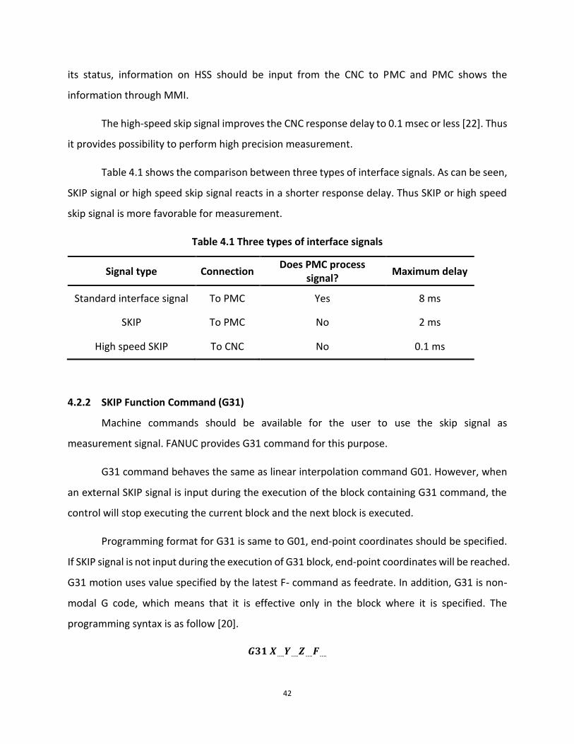
Table 4.1 shows the comparison between three types of interface signals. As can be seen,
SKIP signal or high speed skip signal reacts in a shorter response delay. Thus SKIP or high speed
skip signal is more favorable for measurement.
Table 4.1 Three types of interface signals
Signal type Connection Does PMC process
signal? Maximum delay
Standard interface signal To PMC Yes 8 ms
SKIP To PMC No 2 ms
High speed SKIP To CNC No 0.1 ms
4.2.2 SKIP Function Command (G31)
Machine commands should be available for the user to use the skip signal as
measurement signal. FANUC provides G31 command for this purpose.
G31 command behaves the same as linear interpolation command G01. However, when
an external SKIP signal is input during the execution of the block containing G31 command, the
control will stop executing the current block and the next block is executed.
Programming format for G31 is same to G01, end-point coordinates should be specified.
If SKIP signal is not input during the execution of G31 block, end-point coordinates will be reached.
G31 motion uses value specified by the latest F- command as feedrate. In addition, G31 is non-
modal G code, which means that it is effective only in the block where it is specified. The
programming syntax is as follow [20].
𝑮𝟑𝟏 𝑿….𝒀….𝒁….𝑭….

43
The following is the example illustrating how G31 works:
Y
X
100 200 300 400 500
100
200
300
400
SKIP signal is input here
Finish executing G31 block without SKIP signal input
EXAMPLE:N1 G90 G21 ;N2 G31 X300. F200;N3 G01 X200 Y200;N4 G31 X400;
As can be seen, in block N2, end-coordinate is given as (300, 50) for G31 execution.
However, while the motion is under proceeding, SKIP signal is input. CNC stops the rest
movement of block N2 and executes block N3. In block N4, end-coordinate is also given for G31
execution. This time during the whole G31 motion, SKIP signal is not input. Therefore, the
machine arrives at the end-coordinate as programmed.
Another very important feature of G31 is that it allows users to access the machine
position information where the SKIP signal is input. Coordinates in workpiece coordinate system
when the skip signal is detected by the CNC are stored in system variables (#5061 ~ #5063). The
stored values of these variables can be accessed through custom macros, as discussed before in
chapter 3. For a standard 3-axis milling machine, the system variables number and their
corresponding axis values are shown in Table 4.2.

44
Table 4.2 System variable and machine axis values for SKIP
System variable Machine axis values
#5061 X-axis
#5062 Y-axis
#5063 Z-axis
4.2.3 Application of CNC Measurement Support Functions with Laser Tool Setter
CNC measurement support functions make on-machine measurement system available.
The following are the steps necessary for the tool setter to perform on-machine tool
measurement.
1) Laser tool setter is connected to SKIP input pin of PMC through interface unit, as
described in chapter 2. Therefore, laser tool setter trigger signal is recognized by CNC as SKIP
signal.
2) A tool is loaded into the spindle and G31 command is programmed to drive the tool
to the laser zone of the laser tool setter. As the tool approaching the laser, receiver unit of the
laser tool setter will sense the reduction of laser receiving. When the threshold value is reached,
tool setter trigger signal is generated and CNC stops the machine from moving further, as shown
in Fig 4.1.

45
Tool approaching the laser; Driven by G31 command
Receiver senses reduction in laser; Trigger signal is generated; CNC stops the machine motion
Fig 4.1 Measurement schematics
3) Coordinates of the machine tool when triggered signal is detected by the CNC is
captured and stored in system variable #5061 to #5063. Calculations performing on the stored
values with the aide of custom macro will yield the result of tool length, tool radius or other tool
data.

46
4.3 Measurement Uncertainty
Acquiring an accurate and reliable measurement result is of great importance. Factors
inducing measurement uncertainty will be analyzed in the following text. There are many factors
that can affect the measurement results significantly. However, the most noteworthy factors
relating to reliability of measurement results are residual coolant drops and swarf, alignment
errors, and machine response delay.
4.3.1 Residual Coolant
Incoherent measurement results may be obtained due to the coolant applied on the tool
during most of the CNC machining procedure. Residual coolant can be a very challenging problem
for performing measurement task with laser tool setter. This is because the laser tool setter is
based on non-contact triggered method, trigger signal is not generated by contacting the hard
surface as contact triggered method.
Measurement task will fail if the laser tool setter cannot recognize the falsely triggered
signal generated by coolant drops at any unpredictable moment. Moreover, residual coolant
tends to accumulate on the tip of the tool due to gravity. Thus, if diameter measurement takes
place too close to tool tip, the accumulated coolant will be considered as part of the tool and
error in measurement results will be generated.
To overcome the disadvantages due to the coolant, a high speed could be applied to the
spindle prior to measuring to dislodge the coolant. Air blast can also be used to remove the
residual coolant. To avoid disadvantage of the accumulated coolant near tool tip, measurement
task should take place higher up the tool tip position.

47
4.3.2 Alignment Error
Measurement error will result, if a laser tool setter unit is poorly aligned. For a VMC, the
alignment in X or Y axis affects the radius/diameter measurement results while the alignment in
Z-axis affects the results of tool length measurement. Consider the laser beam should be parallel
to Y-axis of VMC. Fig 4.2 shows the measurement error in radius measurement due to poor
alignment of laser tool setter in Y axis.
Cutting tool
FeedLaser Beam
YX
α
α
Rm
Rtl
Fig 4.2 Misalignment in Y-axis direction
The measurement error due to misalignment in Y-axis direction can be calculated as:
휀𝑦 = |𝑅𝑡𝑙 − 𝑅𝑚| = |𝑅𝑡𝑙 − 𝑅𝑡𝑙/ cos 𝛼|
Eq.4.1
,where 𝑅𝑡𝑙 is the actual tool radius; 𝑅𝑚 is the measured tool radius; 𝛼 is the laser beam
misalignment angle along Y-axis.
Fig 4.3 shows the measurement error due to poor alignment of laser tool setter in Z-axis:

48
Laser Beam
Cutting tool Z
Y
Feed
εz β
β
Rtl
Fig 4.3 Misalignment in Z-axis direction
The measurement error due to misalignment in Z-axis direction can be calculated as:
휀𝑧 = |𝑅𝑡𝑙 ∙ tan𝛽|,
Eq.4.2
where 𝑅𝑡𝑙 is the actual tool radius; 𝛽 is the laser beam misalignment angle along Z-axis.
The signal response time for the laser tool setter is finite. Hence, in some cases, for
example if the lowest point of the tool does not locate on the tool center line and the teeth of
the tool is too small to break the laser beam and to trigger the tool setter, a off-center distance
must be applied before the tool length measurement. Fig 4.4 shows the situation where a boring
bar is measured.

49
Feed
Roffset
Fig 4.4 Tool length measurement with radius offset applied
A radius offset 𝑅offset is applied prior the measurement of tool length to make sure the tooth of
the boring bar blocks enough laser beam. In this case, measurement error due to the
misalignment in Z-axis can be described by Fig 4.5.
Laser Beam
Cutting tool Z
Y
Feed
R
Laser Beam
Cutting tool
Y
X
Roffset
Rtl
Rtl
εz β
β
Fig 4.5 Measurement error due to Z-axis misalignment 2

50
The measurement error due to misalignment in Z-axis direction can be calculated as:
휀𝑧 = |𝑅 ∙ tan𝛽| = |√𝑅𝑡𝑙2 − 𝑅offset
2 ∙ tan 𝛽|.
Eq.4.3
As can be seen from Eq.4.3, the error 휀𝑧 tends to zero as 𝑅offset tends to 𝑅𝑡𝑙. Therefore, when it
is possible, it is favorable to apply radius offset to length measurement. The radius offset can be
set to be slightly inside tool tip radius. This value should be no larger than the tool wear tolerance,
otherwise tool length measurement may fail after the tool wears.
If Y-axis alignment is better than 1mm per 100mm, for the tool with 100 mm in diameter,
according to Eq.4.1, the error would be:
휀𝑦 = |𝑅𝑡𝑙 − 𝑅𝑡𝑙/ cos 𝛼| = 2.5 𝜇𝑚
If Z-axis alignment is better than 10 𝜇𝑚 per 100 mm, for the tool with 100 mm in diameter,
according to Eq.4.2, the error would be:
휀𝑧 = |𝑅𝑡𝑙 ∙ tan𝛽| = 5 𝜇𝑚
The errors in real measurement tasks would not reach value mentioned above as the
errors will be calculated relative to the calibration tool.

51
4.3.3 Trigger Signal Response Delay
Trigger signal response delay is another significant factor that influences the measuring
system. The time sequence of measurement movement, including a tool triggering the tool setter,
CNC obtaining position information and machine tool decelerating is shown in Fig 4.6. Consider
the situation where SKIP signal is used as the tool setter input signal.
L0 L1 L2 L3 L4 L5
F (mm/min)
t (s)
t (s)
t (S)t0 t1 t2 t3 t4 t5
Trigger signal
CNC recognizes signal
Machine tool motion
Fig 4.6 Time sequence for a tool to trigger the tool setter
Machine tool pre-travels to trigger the tool setter (from 𝑡0 to 𝑡1).
The machine advances by the distance of 𝐿1 during this period. It is the distance that the
tool travels from the instant it enters the laser beam to the instant it blocks 50% of the laser
beam and triggers the tool setter. The machine travels with the programmed feedrate during
this period.

52
Machine tool travels due to signal transferring delay (from 𝑡1 to 𝑡2).
The machine advances by the distance of 𝐿2 during this period, due to the delay or
variation of the receiver and interface unit of the tool setter. The machine travels with the
programmed feedrate during this period. 𝐿2 is introduced to measurement results.
Machine tool travels due to CNC response delay (from 𝑡2 to 𝑡3).
The machine advances by the distance of 𝐿3 during this period, due to the time needed
for the CNC to process the SKIP signal and to capture the current position. The machine
travels with the programmed feedrate during this period. 𝐿3 is introduced to the
measurement results.
Machine tool travels due to PMC scan delay [22] (from 𝑡3 to 𝑡4).
The machine advances by the distance of 𝐿4 during this period. Before machine tool starts
to decelerate, PMC must finish one scan and confirm SKIP signal is valid. The machine travels
with the programmed feedrate during this period. However, the distance due to this type of
delay does not affect the measurement results.
Machine tool decelerates (from 𝑡4 to 𝑡5).
The machine advances by the distance of 𝐿5 during this period before reaching a full stop.
The distance 𝐿5 the machine tool travels during this period does not affect the measurement
results.
From the discussion above, the measurement error due to various signal response delay
can be calculated as,
𝛿𝑑𝑒𝑙𝑎𝑦 = 𝐿1 + 𝐿2 + 𝐿3 =𝐹𝑣60× (𝑡3 − 𝑡0)
Eq.4.4
Furthermore, for the same laser tool setter equipped with the same interface unit, the
measurement error cause by pre-travel and interface response is consistent and thus can be

53
calibrated out. However, CNC response time, which varies from 0 msec to 2 msec (with SKIP
signal), is unpredictable. Eq.4.4 can be written as:
𝛿𝑑𝑒𝑙𝑎𝑦 =𝐹𝑣60× (𝑡2 − 𝑡0) +
𝐹𝑣60× (𝑡3 − 𝑡2)
Eq.4.5
The first term on the right hand side of Eq.4.5 is the measurement error that can be compensated,
while the second term will result uncertainty 휀 in calculation readout,
휀 = ±𝐹𝑣60× (𝑡3 − 𝑡2)
Eq.4.6
For example, if the response time for the CNC to capture the machine position is 2 msec,
the measurement readout error due to feedrates can be described in Fig 4.7.
Fig 4.7 Relationship between readout error and feedrate
If readout error should be within the range of ± 1 𝜇𝑚 , the programmed measurement feedrate
cannot be greater than 30 𝑚𝑚/𝑚𝑖𝑛, as can be seen from Fig 4.7. It is also noted that a slower
feedrate is more favorable for measuring as the readout error will be minimized.

54
4.3.4 Compensation Method
As established, signal transferring delay can be considered as a consistent system error
whilst CNC delay is the uncertainty. Thus, only the former delay can be reliably compensated and
variation will always exist in CNC delay. The following method is used to compensate the delay
that affects the measurement results.
Drive the tool to trigger the tool setter at two different speed 𝐹𝑐1 and 𝐹𝑐2. Consider the
signal transferring delay to be 𝑡𝑠 , CNC delay for the two triggers to be 𝑡𝑐𝑛𝑐1 and 𝑡𝑐𝑛𝑐2 . The
recorded positions for two triggers 𝐿𝑐1 and 𝐿𝑐2 can be calculated as:
𝐿𝑐1 = 𝐹𝑐1 ∙ 𝑡𝑠 + 𝐹𝑐1 ∙ 𝑡𝑐𝑛𝑐1
Eq.4.7
𝐿𝑐2 = 𝐹𝑐2 ∙ 𝑡𝑠 + 𝐹𝑐2 ∙ 𝑡𝑐𝑛𝑐2
Eq.4.8
Subtracting Eq.4.8 from Eq.4.7 yields,
𝐿𝑐1 − 𝐿𝑐2 = (𝐹𝑐1 − 𝐹𝑐2) ∙ 𝑡𝑠 + 𝐹𝑐1 ∙ 𝑡𝑐𝑛𝑐1 − 𝐹𝑐2 ∙ 𝑡𝑐𝑛𝑐2
Dividing 𝐹𝑐1 − 𝐹𝑐2 from both sides yields,
𝐿𝑐1 − 𝐿𝑐2𝐹𝑐1 − 𝐹𝑐2
= 𝑡𝑠 +𝐹𝑐1 ∙ 𝑡𝑐𝑛𝑐1 − 𝐹𝑐2 ∙ 𝑡𝑐𝑛𝑐2
𝐹𝑐1 − 𝐹𝑐2
Eq.4.9
Take the left hand side of Eq.4.9 as measurement delay ∆𝑡. As can be seen, signal transferring
delay can be fully compensated. However, the method cannot calibrate out CNC delay.

55
4.4 Measurement Strategy
To perform the measurement task, it is always favorable if the results can be obtain as quick
as possible and as accurate as possible. Certain strategy on measuring the tool should be
employed.
4.4.1 Multi-touch Measurement Strategy
The discussion in section 4.3.3 established that the CNC response time delay introduces
uncertainty into the measurement results. The single triggered measurement strategy is clearly
with a lot of drawbacks, since a high probing feedrate generates large measurement uncertainty
while a small feedrate increases cycle time.
It is more favorable to use multi-touch measurement strategy to perform measurement
tasks. First, the high feedrate is used to drive the tool to trigger the tool setter and then retracts
in a high feedrate. A smaller probing feedrate is used to perform the second triggering from a
relatively closer position to the beam and a high feedrate is still employed to retract the tool. At
last, the tool approaches the tool setter at a very small feedrate from a very close position to the
laser beam to perform the final measurement. To further eliminate the measurement
uncertainty, repeat the last measurement procedure three times and take the average from the
results.
Fig 4.8 shows the motion sequence of a multi-touch measurement cycle.

56
4.4.2 Measurement Cycle Time Calculation
In measurement tasks, the tool is rapidly brought to a position that is close to the laser
beam trigger position. In this position, the distance between the tool and laser beam is called
clearance distance. For example, in radius/diameter measurement, the tool is rapidly brought to
the radius clearance position, as it is shown in the following figure.
Fig 4.8 Motion sequence of a multi-touch measurement cycle
t (s)
Displacement (mm)

57
In the above figure, 𝑄 is the radius clearance distance while 𝐷 is the diameter of the
cutter. The clearance distance 𝑄 ensures the tool does not break the beam and triggers the tool
setter during the rapid positioning. After this rapid positioning, the tool advances toward the
laser beam and start the measurement cycle.
In detail, the distance a tool travels during one measurement motion, comprises four
major parts: clearance distance and pre-travel distance, overtravel due to CNC response delay,
overshoot and back-off travel distance.
1) Clearance distance and pre-travel distance 𝑃1.
For a standard pin with a known diameter, by travelling clearance distance 𝑄 , it should
trigger the tool setter. In this case, 𝑃1 = 𝑄. The time it takes for the pin to cover this distance
can be calculated as,
𝑡1 = 𝑃1/𝐹𝑣
Eq.4.10
D Q
Fig 4.9 Radius clearance position

58
2) Overtravel 𝑃2 due to signal transferring and CNC response delay.
As described previously, it takes time for the trigger signal to reach CNC and for the CNC
to react on the signal. The distance the tool travels during this period of time 𝑡2 can be calculated
as,
𝑃2 = 𝐹𝑣 ∙ 𝑡2
Eq.4.11
3) Overshoot
After the CNC finishes processing the trigger signal, the current position coordinates will
be captured into system variables. If the next block contains no further motion, the machine tool
will decelerate and eventually stop. Therefore, the final position of the machine is not identical
to the captured position. The difference in distance between final position and the captured
position is called overshoot. Overshoot calculation is more complicated than other the
measurement motion distance calculation. Time spent on overshoot distance consists of two
parts: PMC preparation time 𝑡31 and deceleration time 𝑡32, as discussed previously.
PMC preparation time 𝑡31.
As described before, using SKIP signal as tool setter trigger signal, CNC reads the SKIP
signal directly and PMC does not process the SKIP signal. During the time CNC takes to process
the SKIP signal (which is 𝑡2), PMC continues to scan all its input signals, including SKIP input.
Unless PMC successfully scans the valid SKIP signal, the feed would not stop, even if CNC finishes
processing the SKIP signal and decides to skip to the next block. Hence, it takes time 𝑡31 for the
PMC to confirm the SKIP signal and 𝑡31 varies from 0 msec to 8 msec (one PMC scanning period).
During this time, machine tool moves at the programmed feedrate and the distance it travels can
be calculated as:
𝑃31 = 𝐹𝑣 ∙ 𝑡31
Eq.4.12

59
Deceleration time 𝑡32
The time for deceleration consists of two parts. For one part, the machine tool decelerates
in a designated time called time constant 𝑡𝑐 [21] set by a system parameter (No.1622) [23].
Another part of the deceleration period is the time for servo delay.
Considering a linear deceleration profile for a programmed feedrate, the deceleration
𝐷𝑒𝑐 for the machine to reach a full stop, is calculated based on the time constant 𝑡𝑐and the
programmed feedrate 𝐹𝑣:
𝐷𝑒𝑐 = 𝐹𝑣/𝑡𝑐
Eq.4.13
Within the time period 𝑡321 = 𝑡𝑐 , the machine performs purely linear deceleration
motion. However, tasks such as position check and other servo related actions must also be
performed in the process of deceleration and a delay 𝑡322 is introduced. The motion of
deceleration can be described in
Fig 4.10:
F (mm/min)
t (s)
t321 t322
F v
Fig 4.10 Deceleration
While the distance the machine tool travels due to linear deceleration 𝑃321 can be calculated as
𝑃321 =1
2𝐹𝑣 ∙ 𝑡321,

60
the calculation of the distance the machine tool travels due to servo delay 𝑃322 is not trivial. The
overshoot due to deceleration is calculated as
𝑃32 = 𝑃321 + 𝑃322
and the total deceleration time is
𝑡32 = 𝑡321 + 𝑡322
If consider the servo delay time is small enough to ignore, 𝑃32 and 𝑡32 reduce into:
𝑃32 = 𝑃321 =1
2𝐹𝑣 ∙ 𝑡321
𝑡32 = 𝑡321 = 𝑡𝑐
The overall overshoot distance can be calculated as
𝑃3 = 𝑃31 + 𝑃32 = 𝐹𝑣 ∙ (𝑡31 +1
2𝑡𝑐)
Eq.4.14
Overall overshoot delay can be calculated as
𝑡3 = 𝑡31 + 𝑡𝑐
Eq.4.15
4) Back-off travel distance 𝑃4
After the tool triggers the tool setter and stops, it should withdraw to a position that is
enough to reset the tool setter status back to un-triggered. Back off distance 𝑃4 is defined from
the point where the tool halts, as shows in Fig 4.11.

61
Fig 4.11 Measurement cycle motion
𝑃4′ in the figure above is the back off distance by definition. However, since measurement error
exists in information on 𝑃2 and 𝑃3, a larger back of distance 𝑃4 is defined. 𝑃4 can be calculated as:
𝑃4 = 𝑃2 + 𝑃3 + ∆𝑙
Eq.4.16
, where ∆𝑙 is the extra distance added to back off distance to ensure the tool setter reset.
When considering no servo delay, the machine will travel the distance 𝑃4 with either of
the following velocity profiles.
P1 P2 P3
P4
P4'
Start Position
Trigger position
Recorded position
Halt position
Feed
Halt position
Feed

62
In the case of Profile (a), the machine fully accelerates to the programmed back off
feedrate 𝐹𝑏𝑣. The acceleration period will take up one time constant 𝑡𝑐. And since the machine
also needs to decelerate to a full stop, another time constant 𝑡𝑐 is necessary. This type of profile
takes up at least 2 time constants. In the case of Profile (b), due to the limited travel distance,
the high programmed feedrate cannot be reached. CNC will set an equal time period 𝑡4/2 for
acceleration and deceleration and the maximum feedrate can only go up to 𝐹𝑏𝑟. As can be seen,
profile (b) requires less time to cover the same travelling distance.
For profile (a), total time spent on back-off motion can be calculated as:
𝑡4 = (𝑃4 − 𝐹𝑏𝑣 ∙ 𝑡𝑐)/𝐹𝑏𝑣 + 2𝑡𝑐
For profile (b), total time spent on back-off motion can be calculated as:
𝑡4 = √𝑃4 ∙ 𝑡𝑐/𝐹𝑏𝑣
These can also be written as:
𝑡4 =
{
𝑃4 − 𝐹𝑏𝑣 ∙ 𝑡𝑐
𝐹𝑏𝑣+ 2𝑡𝑐 , 𝑃4 > 𝐹𝑏𝑣 ∙ 𝑡𝑐
2 × √𝑃4 ∙ 𝑡𝑐/𝐹𝑏𝑣 , 𝐹𝑏𝑣 ∙ 𝑡𝑐 ≫ 𝑃4 > 0
Fig 4.12 Velocity profile
FF
t t
F_bv
F_bv
F_br
tc tc tc
(a) (b)
t4

63
Eq.4.17
According to the analysis above, the measurement cycle time 𝑡 can be calculated as:
𝑡 = 𝑡1 + 𝑡2 + 𝑡3 + 𝑡4
Eq.4.18
Substituting Eq.4.10, Eq.4.11, Eq.4.14, Eq.4.15, Eq.4.16 and Eq.4.17 into Eq.4.18, yields
𝑡 =
{
𝑃1𝐹𝑣+ 𝑡2 + 𝑡31 + 𝑡𝑐 +
[𝐹𝑣 (𝑡2 + 𝑡31 +
12𝑡𝑐) + ∆𝑙
𝐹𝑏𝑣+ 𝑡𝑐] , 𝐹𝑣 (𝑡2 + 𝑡31 +
1
2𝑡𝑐) + ∆𝑙 > 𝐹𝑏𝑣 ∙ 𝑡𝑐
𝑃1𝐹𝑣+ 𝑡2 + 𝑡31 + 𝑡𝑐 +
2 × √[𝐹𝑣 (𝑡2 + 𝑡31 +1
2𝑡𝑐) + ∆𝑙] ∙ 𝑡𝑐/𝐹𝑏𝑣 , 𝐹𝑏𝑣 ∙ 𝑡𝐶 ≫ 𝐹𝑣 (𝑡2 + 𝑡31 +
1
2𝑡𝑐) + ∆𝑙 > 0
Eq.4.19
where,
𝑃1 is clearance distance and pre-travel distance;
𝐹𝑣 is the programmed probing feedrate;
𝑡2 is signal transferring and CNC response delay;
𝑡31 is PMC preparation time;
𝑡𝑐 is the time constant for CNC machine;
𝐹𝑏𝑣 is the programmed back-off movement feedrate;
∆𝑙 is the extra travel distance for back-off movement that ensures the tool setter to be reset.
In addition, since the second and final touch are performed at relatively smaller feedrates,
the uncertainty of the measured position is less significant. Therefore, back-off distance can be
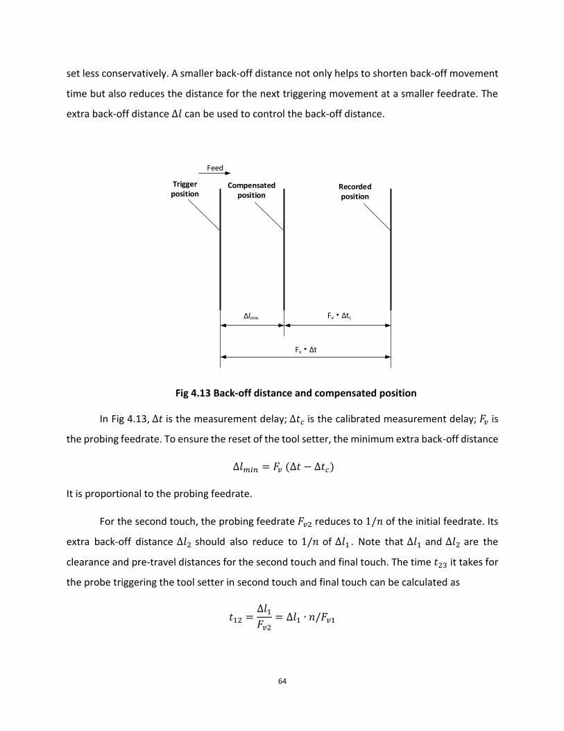
64
set less conservatively. A smaller back-off distance not only helps to shorten back-off movement
time but also reduces the distance for the next triggering movement at a smaller feedrate. The
extra back-off distance ∆𝑙 can be used to control the back-off distance.
Feed
Trigger position
Compensated position
Recorded position
Fv • ∆tc∆lmin
Fv • ∆t
Fig 4.13 Back-off distance and compensated position
In Fig 4.13, ∆𝑡 is the measurement delay; ∆𝑡𝑐 is the calibrated measurement delay; 𝐹𝑣 is
the probing feedrate. To ensure the reset of the tool setter, the minimum extra back-off distance
∆𝑙𝑚𝑖𝑛 = 𝐹𝑣 (∆𝑡 − ∆𝑡𝑐)
It is proportional to the probing feedrate.
For the second touch, the probing feedrate 𝐹𝑣2 reduces to 1/𝑛 of the initial feedrate. Its
extra back-off distance ∆𝑙2 should also reduce to 1/𝑛 of ∆𝑙1 . Note that ∆𝑙1 and ∆𝑙2 are the
clearance and pre-travel distances for the second touch and final touch. The time 𝑡23 it takes for
the probe triggering the tool setter in second touch and final touch can be calculated as
𝑡12 =∆𝑙1𝐹𝑣2
= ∆𝑙1 ∙ 𝑛/𝐹𝑣1

65
𝑡13 =∆𝑙2𝐹𝑣3
=∆𝑙1𝑛 ∙ 𝐹𝑣3
𝑡23 = 𝑡12 + 𝑡13 = ∆𝑙1 ∙𝑛
𝐹𝑣1+
∆𝑙1𝑛 ∙ 𝐹𝑣3
Eq.4.20
The following set of parameters is the typical value for a measurement task.
Table 4.3 Parameters for measurement cycle time
Parameter’s Name Symbol Value Unit
Initial clearance distance & pre-travel distance
𝑃11 5 𝑚𝑚
Initial Probing feedrate 𝐹𝑣1 3000 𝑚𝑚/𝑚𝑖𝑛
Final touch probing feedrate 𝐹𝑣3 6 𝑚𝑚/𝑚𝑖𝑛
Signal transferring and CNC response delay 𝑡2 0.0013 𝑠
PMC preparation time 𝑡31 0.004 𝑠
Time constant for CNC machine 𝑡𝑐 0.06 𝑠
Back-off motion feedrate 𝐹𝑏𝑣 3000 𝑚𝑚/min
First extra travel distance for back-off motion ∆𝑙1 1.2 𝑚𝑚
Eq.4.20 has a minimum at 𝑛 = 22.36 . Take 𝑛 = 22 , the measurement cycle time can be
calculated to be 𝑡 = 13.106 𝑠.
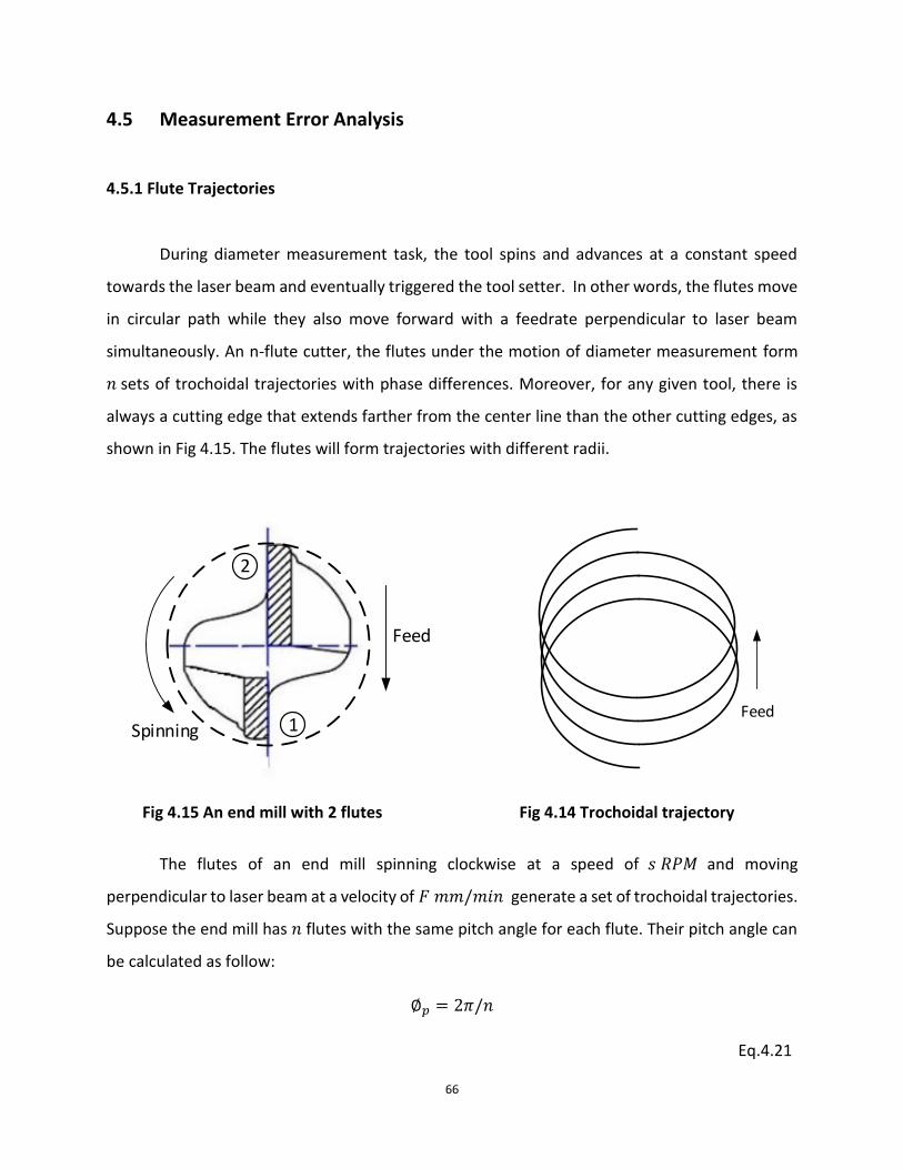
66
4.5 Measurement Error Analysis
4.5.1 Flute Trajectories
During diameter measurement task, the tool spins and advances at a constant speed
towards the laser beam and eventually triggered the tool setter. In other words, the flutes move
in circular path while they also move forward with a feedrate perpendicular to laser beam
simultaneously. An n-flute cutter, the flutes under the motion of diameter measurement form
𝑛 sets of trochoidal trajectories with phase differences. Moreover, for any given tool, there is
always a cutting edge that extends farther from the center line than the other cutting edges, as
shown in Fig 4.15. The flutes will form trajectories with different radii.
The flutes of an end mill spinning clockwise at a speed of 𝑠 𝑅𝑃𝑀 and moving
perpendicular to laser beam at a velocity of 𝐹 𝑚𝑚/𝑚𝑖𝑛 generate a set of trochoidal trajectories.
Suppose the end mill has 𝑛 flutes with the same pitch angle for each flute. Their pitch angle can
be calculated as follow:
∅𝑝 = 2𝜋/𝑛
Eq.4.21
Spinning
Feed
1
2
Feed
Fig 4.14 Trochoidal trajectory Fig 4.15 An end mill with 2 flutes

67
Their trajectories can be represented by a set of parametric equations with time 𝑡 as variable:
{ 𝑥1 = 𝑥𝑠 + 𝐹 ∙ 𝑡/60 + 𝑟1 ∙ cos(−𝜔𝑡 + 𝜑)
𝑦1 = 𝑦𝑠 + 𝑟1 ∙ sin(−𝜔𝑡 + 𝜑)
,
{ 𝑥2 = 𝑥𝑠 + 𝐹 ∙ 𝑡/60 + 𝑟2 ∙ cos(−𝜔𝑡 + ∅𝑝 + 𝜑)
𝑦2 = 𝑦𝑠 + 𝑟2 ∙ sin(−𝜔𝑡 + ∅𝑝 +𝜑)
,
…
{ 𝑥𝑖 = 𝑥𝑠 + 𝐹 ∙ 𝑡/60 + 𝑟𝑖 ∙ cos[−𝜔𝑡 + (𝑖 − 1) ∙ ∅𝑝 + 𝜑]
𝑦𝑖 = 𝑦𝑠 + 𝑟𝑖 ∙ sin[−𝜔𝑡 + (𝑖 − 1) ∙ ∅𝑝 + 𝜑]
,
…
{ 𝑥𝑛 = 𝑥𝑠 + 𝐹 ∙ 𝑡/60 + 𝑟𝑛 ∙ cos[−𝜔𝑡 + (𝑛 − 1) ∙ ∅𝑝 + 𝜑]
𝑦𝑛 = 𝑦𝑠 + 𝑟𝑛 ∙ sin[−𝜔𝑡 + (𝑛 − 1) ∙ ∅𝑝 + 𝜑]
,
Eq.4.22
where 𝜔 (radius per second) represents the angular velocity the tool spinning speed and can be
calculated as:
𝜔 = 2 ∙ 𝜋 ∙ 𝑠/60,
Eq.4.23
𝑟1 ,𝑟2, 𝑟𝑖…𝑟𝑛 are the distances each flute extends from the center point respectively, 𝜑 is the
starting phase and (𝑥𝑠, 𝑦𝑠) is the starting position of the end mill.

68
Fig 4.16 shows the trajectory that a flute circumscribes during the diameter measurement
task. The trajectory is a trochoidal curve made of repeating patterns. The pattern starts at P1 and
ends at P4, marked in Fig 4.16. This pattern repeats itself in the next period of time 𝑇 until the
flute reaches trigger position P6. During each period, a point in a pattern advances by the distance
of:
∆𝑙 = 𝐹/𝑠
Eq.4.24
If the trigger position of the tool setter is 𝑥𝑡 , when the 𝑖th flute arrives at the trigger
position, we have
𝑥𝑡 − 𝑥𝑖 = 0.
Eq.4.25
When the flute triggers the tool setter at P6, the tool center point Xct subtends an angle 𝜃𝑡 to the
positive x-axis.
X2
Trigger Position
P6
Xt
X
Y
P2
P1
P11
P3
P4
P5
X5
X11
Xct
θt
θ
Xc
Fig 4.16 Flute trajectory for one flute

69
4.5.2 Condition for the Correct Trigger Status
When the tool is spun clockwise and is moved towards the laser beam from the left side
of the laser beam, the only correct trigger status is that when the flute triggers the tool setter,
the tool center should not pass the beam and should locate at the right side of the beam. Based
on this condition, the range for angle 𝜃𝑡 for the tool to trigger the tool setter correctly can be
derived.
Consider tool center position is (0,0) at 𝑡 = 0 . The parametric equation for tool center
point can be written as:
{ 𝑥𝑐 = 𝑥𝑠 + 𝐹 ∙ 𝑡/60 = 𝐹 ∙ 𝑡/60
𝑦𝑐 = 𝑦𝑠 = 0
.
Eq.4.26
When a flute triggers the tool setter with an angle 𝜃𝑡, the parametric equation for a flute can be
written as
{𝑥𝑓 = 𝐹 ∙ 𝑡/60 + 𝑟 ∙ cos(𝜃𝑡)
𝑦𝑓 = 𝑟 ∙ sin(𝜃𝑡) .
Eq.4.27
If the time it takes for the flute to trigger the tool setter is 𝑡𝑡, the tool center position in x direction
is
𝑥𝑐 = 𝐹 ∙ 𝑡𝑡/60.
Eq.4.28
The flute position at trigger position in x direction is
𝑥𝑓 = 𝐹 ∙ 𝑡𝑡/60 + 𝑟 ∙ cos(𝜃𝑡) = 𝑥𝑡.
Eq.4.29

70
Since at trigger position, the tool center must locate on the left of the laser beam,
𝑥𝑐 < 𝑥𝑡.
Eq.4.30
Substitutes Eq.4.28 and Eq.4.29 in to inequality Eq.4.30, we have
𝐹 ∙ 𝑡𝑡/60 < 𝐹 ∙ 𝑡𝑡/60 + 𝑟 ∙ cos(𝜃𝑡)
Therefore, we have:
𝜃𝑡 ∈ (−𝜋/2, 𝜋/2).
This is the necessary and sufficient condition for the tool to trigger the tool setter correctly.

71
4.5.3 Relation between Feedrate, Spindle Speed and Flute Radius
To guarantee the flute to trigger the tool setter correctly, namely 𝜃𝑡 ∈ (−𝜋/2, 𝜋/2), the
form of the flute trajectory must satisfy certain requirements. Since different feedrate, spindle
speed and flute radius can result in different trajectory profiles, by finding out the trajectory form
in critical condition resulting by these parameters, the relation between feedrate, spindle speed
and flute radius can be derived.
The following experiments have been conducted to visualize the combination of spindle
speed and feedrate at critical condition for one-flute tools with different radii. Six experiments
have been done with the flute lengths 𝑟 ranging from 1mm to 6mm. When the spindle speed
ranges from 800 rmp to 3000 rmp, the corresponding feedrate under critical condition for
different flute length is plot in Fig 4.17.
As can be seen from Fig 4.17, each flute length corresponds to a curve. Only spindle speed
and feedrate combinations on the left upper side area of the curve are available for selection in
order to gain correct measurement results. For example, when measuring a 𝑟 = 3𝑚𝑚 one-flute
Fig 4.17 Relationship between spindle speed and feedrate

72
tool with a spindle speed 𝑠 = 1000 𝑅𝑃𝑀, the maximum feedrate cannot exceed 4000 𝑚𝑚/𝑚𝑖𝑛;
when measuring a 𝑟4 one-flute tool with a spindle speed 𝑠 = 800 𝑅𝑃𝑀, the maximum feedrate
cannot exceed 4400 𝑚𝑚/𝑚𝑖𝑛 . Otherwise, the boring tool will not trigger the tool setter
correctly.
It can also be seen that for the same flute length, the lower spindle speed is used, the
lower the maximum feedrate is available for selection. In addition, the larger the flute radius is,
the curve tends to locate farther to the right, meaning that with the same spindle speed, the
larger the flute length is, the larger the maximum feedrate can be.

73
4.5.4 Application of the Relation between Spindle Speed, Feedrate and Radius
The choice of combination of spindle speed and feedrate determines validity of the
measurement task. The choice should be made according to the Fig 4.17. Choosing the valid
combination of spindle speed and feedrate according to flute length, is extremely important in
boring bar measurement. Because the tooth of a boring bar can miss the laser beam and trigger
the tool setter with an incorrect status, when feedrate is too large, spindle speed is too small or
flute length is too small.
Normally, there are two forms of boring bar: 1) A boring bar with the farthest extended
point also as the lowest point of the cutter, as shown in Fig 4.18; 2) A boring bar with the farthest
extended point not as the lowest point of the cutter, as shown in Fig 4.19.
R
R
R’
For a boring bar with a form shown in Fig 4.18, to accurately measure the tool radius, it is
important to measure the lowest point of the boring bar. Therefore, during measurement, the
tool should locate at a position as shown in the following figure.
Fig 4.18 Type 1 boring tool Fig 4.19 Type 2 boring tool

74
S
Fv
Because the farthest extended point is the lowest point of the boring bar, if with a poorly
chosen spindle speed and feedrate combination, the undesired trigger status, where the flute
triggers the tool setter with 𝜃𝑡 ∉ [−𝜋/2, 𝜋/2], may occur. For example, if a ∅8 boring bar is spun
at 𝑠 = 800 𝑅𝑀𝑃 , the feedrate 𝐹𝑣 = 5000 𝑚𝑚/𝑚𝑖𝑛 is chosen. According to Fig 4.17, this
combination lies on the lower right area of the curve for 𝑟 = 4𝑚𝑚. When the tool triggers the
tool setter, its center may locate on the right side of the beam, as shown in the following figures.
In consequence, a wrong tool radius will be calculated.
Fig 4.20 Beam position

75
S
Fv
S
Fv
For a boring bar with the other form shown in Fig 4.19, to measure the tool radius, the
position of the boring bar should locate as Fig 4.22 shown.
R
R’
S
Fv
A boring bar with this form, a poorly chosen spindle speed and feedrate combination, the
undesired trigger status, where the flute rigger the tool setter with 𝜃𝑡 ∉ [−𝜋/2, 𝜋/2], may occur
too. For example, if a ∅8 boring bar is spun at 𝑠 = 800 𝑅𝑀𝑃, the feedrate 𝐹𝑣 = 5000 𝑚𝑚/𝑚𝑖𝑛
is chosen. According to Fig 4.17, this combination lies on the right side of the curve for 𝑟 = 4𝑚𝑚.
When the tool triggers the laser beam, the tool center will not be on the right side of the laser
Fig 4.21 Unfavorable trigger condition for type 1 boring bar
Fig 4.22 Beam position for type 2 boring bar

76
beam. A trigger situation, where it is the wrench instead of the flute that triggers the tool setter,
may occur, as Fig 4.23 shown. In consequence, a wrong tool radius will be calculated.
S
Fv
S
Fv
Fig 4.23 Unfavorable trigger condition for type 2 boring bar

77
CHAPTER 5 APPLICATION
5.1 Introduction
In this chapter, application of on-machine measurement system with laser tool setter will
be described. The effect of the application on improving stability of manufacturing is also
discussed.
5.2 Experiment
Experiments are carried out on a BridgePort/Hardinge VMC1500P 3-axis vertical mill
equipped with FANUC 0i-MC control. Calibration and measurement cycles are programmed in
FANUC Custom Macros and installed to the machine control through RS232 serial interface. NC-
4/NCi-5 unit produced by Renishaw is selected as laser tool setter and interface unit. To better
eliminate the measurement uncertainty, high speed SKIP signal is used for tool setter trigger
signal.
Calibration cycles are run prior any measurement task is performed. These cycles are
intended to “tell” the machine where the laser tool setter locates and to compensate the
consistent system error. Measurement cycles are embedded into part programs, automating the
tool measurement tasks. For example, measurement cycles are added after tool change so that
every time the machine finishes changing the tool, it will measure the current tool data. The
results of radius measurements of three different two-flute milling tools are shown in Table 5.1.

78
Table 5.1 Radius measurement results (units: mm)
Tool Number
Manual radius measurement
result
Tool setter radius measurement result
1
Tool setter radius measurement result
2
Tool setter radius measurement result
3
1 9.958 10.008 10.007 10.007
2 5.901 5.924 5.924 5.925
3 3.375 3.508 3.508 3.508
The radius measurement experiments conducted above are under the conditions of final
probing feedrate 𝐹𝑣 = 2 𝑚𝑚/𝑚𝑖𝑛 and the tool spinning at 𝑆 = 1000 𝑟𝑒𝑣/𝑚𝑖𝑛. Measurement
uncertainty is no more than 0.001 mm. The repeatability of measurement results from the table
above shows reliability. Also it is worth mentioning that, the measurement results gained from
tool setter are larger than manual radius measurement results. This is because while measuring
with tool setter, the tool rotates and thus spindle run out is added into the measuring results.
On the other hand, since high speed SKIP is used as trigger signal, the CNC response delay
is no more than 0.1 msec. Thus the hardware delay compensation method described in section
4.3.3 has a very good result. Therefore, the repeatability and accuracy of the measurement
system is acceptable for industry use. Fig 5.1 shows the tool is being measured by the tool setter.

79
5.3 Application with Out-Of-Tolerance Warning Feature
Further application can be made in order to prevent the situation where an out-of-
tolerance tool is used to perform the machining task. The purpose can be achieved through
editing measurement cycles macros. The following two parameters are introduced: The
maximum initial input radius wear 𝑅𝑤1 and the maximum radius wear compared to the initial
radius value 𝑅𝑤2. The edited cycle performs the following tasks:
Checks if the radius wear input to the control registry is larger than 𝑅𝑤1 , if the input is
initial; If yes, an out-of-tolerance warning is issued.
Checks if the difference between the current input radius wear and the initial radius wear
is larger than 𝑅𝑤2 ; if yes, an out-of-tolerance warning is issued.
In the case of manual input radius wear information, mistakes always happen when it is
required to input decimal. For example, the correct radius wear is -0.043 mm but the value to
the control registry is mistakenly input to be -0.43mm. A 10-time difference is added. The
application described in this section prevents situations like these.
Fig 5.1 Measurement with laser tool setter
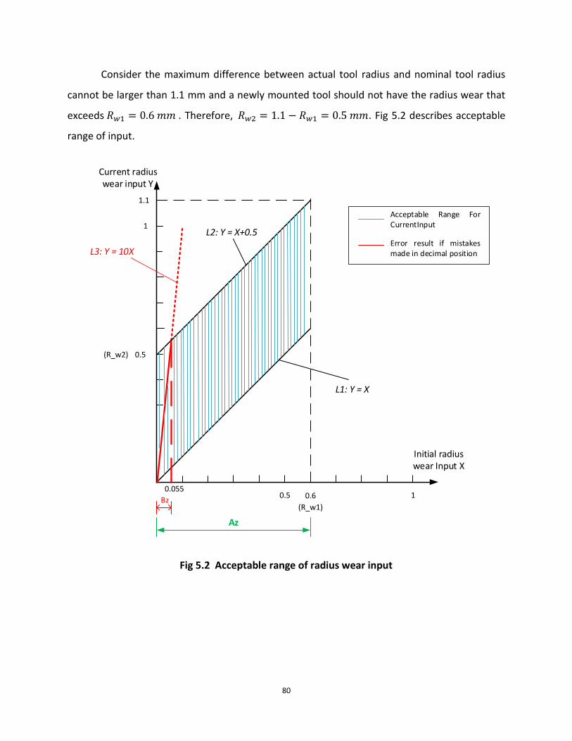
80
Consider the maximum difference between actual tool radius and nominal tool radius
cannot be larger than 1.1 mm and a newly mounted tool should not have the radius wear that
exceeds 𝑅𝑤1 = 0.6 𝑚𝑚 . Therefore, 𝑅𝑤2 = 1.1 − 𝑅𝑤1 = 0.5 𝑚𝑚. Fig 5.2 describes acceptable
range of input.
0.5 0.6
(R_w1) 1
1.1
1
(R_w2) 0.5
0.055
Initial radius wear Input X
Current radius wear input Y
Az
Acceptable Range For CurrentInput
Bz
Error result if mistakes made in decimal position
L1: Y = X
L2: Y = X+0.5
L3: Y = 10X
Fig 5.2 Acceptable range of radius wear input

81
For the initial radius wear input, the input value must fall into the range of 𝐴𝑧, as shown
in Fig 5.2. In the case of the updated radius wear input, the input value must fall into the region
specified by the blue lines. Consider the manual input error is misreading the decimal position,
which yields a 10-time difference in value. The mistaken values follow the line 3 depicted with
red color in the figure above. At 𝑋 = 0.5555 𝑚𝑚, line 3 intersects with line 2. This means that,
in the range of 𝐵𝑧 ,from 0 to 0.555 mm, the program cannot warn about the input error due to
misread decimal position. However, outside of the range of 𝐵𝑧, this type of human error can be
fully prevented.

82
CHAPTER 6 CONCLUSIONS AND FUTURE WORK
6.1 Conclusions
In this work, a method to performed on-machine tool measurement tasks is proposed
with the help of laser based tool setter. Analysis has been carried out on the laser tool setters’
hardware structure and the components of the CNC system structure. To further pinpoint the
measurement uncertainty, the effects on measurement results due to residual coolant, geometry
effect and CNC response delay are studied. The maximum deviation in measurement results are
derived according to a more accurate mathematical model and compensation method is
explained. These give a better understanding on the measurement system ability. To perform the
measurement tasks, a dedicated software (measurement cycles) must be installed in the CNC
control. This software is written with the aid of FANUC custom macros, which is described in
detail in Chapter 3. The major concerns of any measurement are how to gain a result as accurate
as possible and as fast as possible. To accomplish these, examination on measurement cycle time
is carried out and a multi-touch method with an optimized probing feedrate is proposed.
The result of the applications prove that the repeatability and reliability of the
measurement method. By employing out-of-tolerance check, situations where tools of excessive
wear are still used for machining can be avoided.
6.2 Future work
For further research, the following topics can be considered to expand the present work:
To obtain the more detailed compensation data, such as machine error and temperature
difference.

83
CAM software can be developed. According to the machine position of the tool setter and
workpiece, the software can simulate the on-machine measurement tasks to avoid collision in
actual working environment. In addition, parameters of the tool can be taken into consideration
in order to choose the best set of input for measurement cycle.

84
Bibliography
1. Mou, J., and C. Richard Liu. "A method for enhancing the accuracy of CNC machine tools for on-
machine inspection." Journal of Manufacturing Systems11.4 (1992): 229-237.
2. Hollingum, Jack. "Renishaw automate programming and machining to micron accuracy." Sensor
Review 17.3 (1997): 223-230.
3. Kurada, S., and C. Bradley. "A review of machine vision sensors for tool condition
monitoring." Computers in Industry 34.1 (1997): 55-72.
4. Morrison, Robert B., and Peter K. Hellier. "Touch probe." U.S. Patent No. 6,275,053. 14 Aug. 2001.
5. Stimpson, Victor G., et al. "Position determining apparatus for coordinate positioning machine." U.S.
Patent No. 6,496,273. 17 Dec. 2002.
6. Stimpson, Victor G., et al. "Optical measuring apparatus for measuring objects on machines." U.S.
Patent No. 6,878,953. 12 Apr. 2005.
7. Merrifield, Benjamin J., and Victor G. Stimpson. "Measuring device and method for detecting objects
interrupting a beam of radiation." U.S. Patent No. 7,312,433. 25 Dec. 2007.
8. Egglestone, Edward Benjamin, Derek Marshall, and Benjamin Jason Merrifield. "Tool setting or analysis
device." U.S. Patent Application 13/960,347.
9. Lee, Hyeon-Hwa, et al. "A compact high-precision optical sensor for three-dimensional tool-origin
compensation." International Journal of Precision Engineering and Manufacturing 12.3 (2011): 543-549.
10. Lynch, Mike. Parametric Programming for Computer Numerical Control Machine Tools and Touch
Probes: CNC's Best-kept Secret. Society of Manufacturing Engineers, 1997.
11. Huang Shimei, and Can Wenliang.”The application of Macro-based electronics cutter aligner in the
machining center”. Machine Tool & Hydraulics, 39.10 (2011): 57-59.
12. Huang Jiyong. Research on Tool Auto-checking Instrument for NC lathe. MS thesis. Shenyang
University of Technology, 2005.
13. Lee, Eung Suk, Chan Ho Lee, and Sung Chung Kim. "Machining accuracy improvement by automatic
tool setting and on machine verification." Key Engineering Materials 381 (2008): 199-202.
14. Renishaw. “One-touch vs Two-touch probing strategies”, Vol.1 (2011), H-5650-2015-01
15. Renishaw. “Renishaw’s non-contact laser tool setting technology”, Vol.1 (2011), H-6550-2024-01-B
16. Renishaw. ”Optimising measurement cycle time”, Vol.1 (2011). H-6560-2016-01-A
17. Suh, Suk-Hwan, et al. Theory and design of CNC systems. Springer, 2008.
18. FANUC. ”FANUC Series 0i-MODEL D PMC PROGRAMMING MANUAL”, B-64393EN/02
19. Smid, Peter. Fanuc CNC Custom Macros: Programming Resources for Fanuc Custom Macro B Users.
Industrial Press Inc., 2004.
20. FANUC. ”FANUC Series 0i-MC OPERATOR’S MANUAL”, B-64124EN-1/01

85
21. FANUC. ”FANUC Series 0i-MODEL D CONNECTION MANUAL (FUCNTION)”, Vol.1. B-64303EN-1/02
22. FANUC. ”FANUC Series 0i-MODEL D CONNECTION MANUAL (FUCNTION)”, Vol.2. B-64303EN-1/02
23. FANUC. ”FANUC Series 0i-MODEL D PARAMETER MANUAL”, B-64120EN-1/01