Embed Size (px)
Citation preview

research activities on Systems/Components- Highlights -

Dr. Andrea VaccaMAHA Assistant professorPurdue University Activities on systems/components
Projects List:
1. Complete analysis of an aerial platform (articulated boom lift) and its hybridization
2. Analysis of a tractor rear hitch control for agricultural tractor
3. Analysis of a of Diesel/CVT power split transmission
Systems
4. Analysis, design and optimization of power supply systemsdiscrete flow rate supply system electro-hydraulic system for the displacement control in axial piston pumps
5. Design of a LS flow divider valve for an hydraulic steering system
Systems - Components
New research project
6. Adaptive control strategies for the cancellation of low frequency disturbances

Dr. Andrea VaccaMAHA Assistant professorPurdue University
Project 1: Articulated aerial boom lift platform (a)
Goals
Analysis of the HTFig 1b – Schematic of the HT
Fig 1a – prototype of the articulated boom lift
Activities on systems/components
Fig 1c – AMESim model of the HT
ICE
• Analysis of the hydrostatic transmission and optimization of its operation• Analysis and design of the hydraulic system for the boom lift• Design and control optimization of the hydr. system for a Diesel-electro-hydraulic hybrid solution

Project 1: Articulated aerial boom lift platform (b)
Analysis of the HT(cont)
Fig 1d – idea under the AMESim
model: system modeling starting from
the vehicle drive cycle
Dr. Andrea VaccaMAHA Assistant professorPurdue University Activities on systems/components

Dr. Andrea VaccaMAHA Assistant professorPurdue University
Project 1: Articulated aerial boom lift platform (c)
Analysis and design of the HT
Fig 1d – Example of HT predicted performance: output torque and power losses of the hydraulic system
Activities on systems/components
Fig 1e – Example of HT predicted performance: fuel consumption
over a selected drive cycle (A,B,C,D: different designs of the HT)
Reduction of fuel consumption of about 15% respect to the
traditional HT system
Dr. Andrea VaccaMAHA Assistant professorPurdue University
Project 1: Articulated aerial boom lift platform (c)
Analysis of the hydraulic system for the boom lift
Activities on systems/components
Fig 1f – Schematic of the hydraulic system
Fig 1g – The AMESim model of the system
Dr. Andrea VaccaMAHA Assistant professorPurdue University
Project 1: Articulated aerial boom lift platform (d)
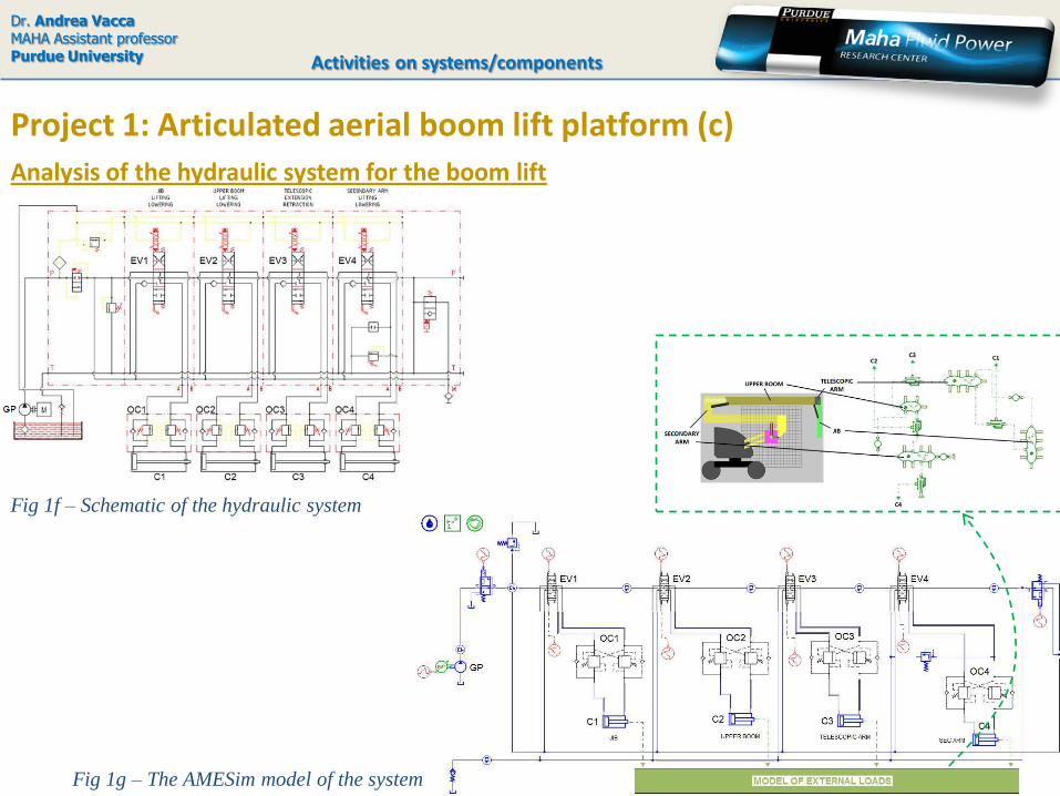
Analysis of the hydraulic system for the boom lift
Activities on systems/components
Fig 1j – The AMESim model of the system
Fig 1h – patented flow control valve
A patented flow control valve is used into the system,The valve permits a good flow regulation in each actuatorwithout the use of external LS signal lines
Fig 1i – Simplified scheme of the valve

Dr. Andrea VaccaMAHA Assistant professorPurdue University
Project 1: Articulated aerial boom lift platform (e)
Analysis of the hydraulic system for the boom lift
Activities on systems/components
Fig 1k – Valve verification tests
The flow control valve required the development of a detailed simulation model (AMESim®). Tests were performed with the purpose of model validation

Dr. Andrea VaccaMAHA Assistant professorPurdue University
Project 1: Articulated aerial boom lift platform (f)
Analysis of the hydraulic system for the boom lift
Activities on systems/components
Fig 1l – Principle of hybridization
Energy saving of about 50% respect to the traditional
hydraulic system
Once the model has been validated (using also on field measurements on a machine prototype) the best control strategy has been defined.The new control strategy considers a variable pump speed, achievable by means of the overall hybridization of the machine.
Fig 1m – Estimated power request for
the optimal control solution for the
reference drive cycle

Dr. Andrea VaccaMAHA Assistant professorPurdue University
Project 1: Articulated aerial boom lift platform (g)
Conclusion – final remarks
Activities on systems/components
•The research permitted to optimize the HT and the whole hydraulic system of the machine.•The integration with the electric hybrid system is under development
For more details..• write to [email protected] • see published papers:- Vacca, A., Franzoni, G., Bonati, F., 2008, An Inclusive, System-Oriented Approach for the Study and the Design of
Hydrostatic Transmissions: The Case of an Articulated Boom Lift, SAE Int. Journal of Commercial Vehicles vol. 1,
April 2009 pp. 488-494.
- Bonati, F., Franzoni, G., Vacca, A., 2007, Trasmissioni Idrostatiche per Piattaforme Aeree Articolate (in italian),
Oleodinamica-Pneumatica – Tecniche Nuove, Milano. N. 11 Dicembre 2007. Pubblished also in Fluid – Trasmissioni
di Potenza n. 3 Maggio 2008.
-Campanella G., Vacca A., 2010, Modeling and optimization of the control strategy for the hydraulic system of
an articulated boom lift , 2010 SAE Commercial Vehicle Engineering Congress and Exhibition, October 5-6, 2010.
Rosemont, Illinois, USA.

Dr. Andrea VaccaMAHA Assistant professorPurdue University
Project 2: Tractor rear hitch control for agricultural tractors (a)
Goals
Activities on systems/components
a project completely performed at the University of Parma, Italy
This research is part of a project (supported by the Italian government; CNH as industrial partner):aimed to develop a parametric numerical model for the simulation of the dynamics of a smalltractor. Parts considered: ICE & transmission system, auxiliaries; rear hitch.
Fig 2b – The hydraulic system and the
control valve used in the CNH system
The system
Fig 2a – The hitch control system
(source: Bosh Rexroth)
Particular goals: • analysis of the hydraulic system (rear hitch)• individuation of power losses and
formulation of possible improvements• dynamic analysis and definition of
possible improvement of control strategy

Dr. Andrea VaccaMAHA Assistant professorPurdue University
Project 2: Tractor rear hitch control for agricultural tractors (b)
The approach
Activities on systems/components
Anti-shock and anti-cavitation relief valve
Fig 2c – CFD simulation for the verification of flow forces and
throat areas used in the lumped parameters model Fig 2d – Predicted vs measured
characteristic of the valve
Detailed simulation of each element of the main valve (AMESim® model)
a project completely performed at the University of Parma, Italy
Dr. Andrea VaccaMAHA Assistant professorPurdue University
Project 2: Tractor rear hitch control for agricultural tractors (c)
The approach
Activities on systems/components
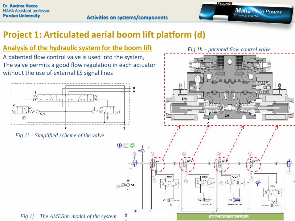
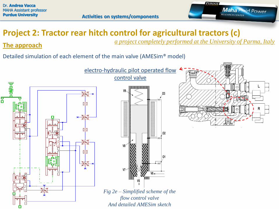
electro-hydraulic pilot operated flow control valve
Fig 2e – Simplified scheme of the
flow control valve
And detailed AMESim sketch
Detailed simulation of each element of the main valve (AMESim® model)
a project completely performed at the University of Parma, Italy
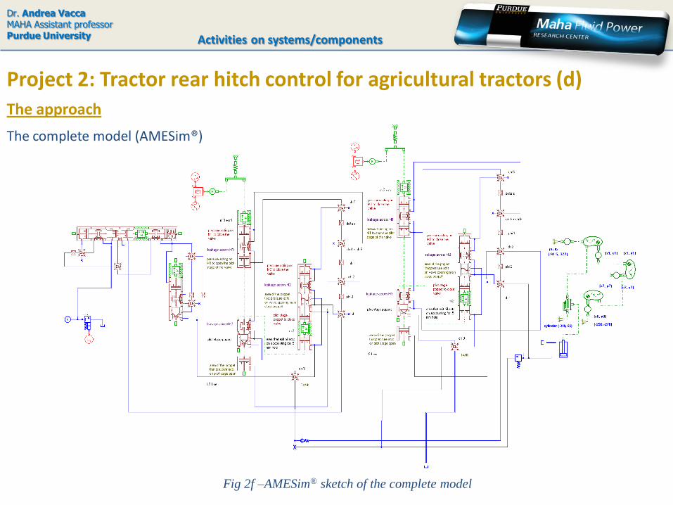
Fig 2f –AMESim® sketch of the complete model
The complete model (AMESim®)
Project 2: Tractor rear hitch control for agricultural tractors (d)
The approach
Dr. Andrea VaccaMAHA Assistant professorPurdue University Activities on systems/components

Dr. Andrea VaccaMAHA Assistant professorPurdue University
Project 2: Tractor rear hitch control for agricultural tractors (d)
Model verification
Activities on systems/components
Verification of the model on the basis of experimental results
Fig 2g – Test performed on the valve
Fig 2h – Simulation results vs.
experimental data
a project completely performed at the University of Parma, Italy

Dr. Andrea VaccaMAHA Assistant professorPurdue University
Project 2: Tractor rear hitch control for agricultural tractors (e)
Simulation results
Activities on systems/components
Simulation of generic driving cycles
0
20
40
60
80
100
120
140
0 10 20 30 40 50 60
Pre
ssu
re
[B
ar]
-F
low
ra
te
[L
/m
in]
Time [s]PL [Bar] Q [L/min] PS [Bar] PM [Bar]
Reference Column for Energy Analysis
Reference Column for Energy Analysis
10000 N 20000 N Secondary User and 10000 N
39%
28%
21%
12%
Useful Power 39 %
Power Losses through PC 28%
Power Losses through FCV 21%
Power Losses from FCV to Actuator 12%
Fig 2i – Simulation of a driving cycle
Fig 2j – Power dissipation
a project completely performed at the University of Parma, Italy

Dr. Andrea VaccaMAHA Assistant professorPurdue University
Project 2: Tractor rear hitch control in agricultural tractors (f)
Dynamic analysis
Activities on systems/components
Derivation of a linearized model
Fig 2k – Flow at load original system
Frequency analysis
Fig 2l – Flow at load new proposal
a project completely performed at the University of Parma, Italy

Dr. Andrea VaccaMAHA Assistant professorPurdue University
Conclusion – final remarks
Activities on systems/components
For more details..• write to [email protected]; [email protected] • see published papers:-Vacca, A., Franzoni, G., Casoli, P., 2004, Experimental investigation on a hydraulic special pressure control valve,
3rd Fluid Power Net International PhD Symposium, Technical University of Catalonia, Terrassa – Spain, 30th June –
2nd July 2004
-Casoli, P., Vacca, A., 2007, Design Optimization of a Special Relief Valve with Response Surface Methodology, PTMC
2007, Bath Symposium on Power Transmission & Motion Control, September 12-14, 2007, Bath, UK
- Casoli P., Vacca A., Anthony A., Berta G.L., 2010, Numerical and Experimental Analysis of the Hydraulic Circuit for
the Rear Hitch Control in Agricultural Tractors, 7IFK International Fluid Power Conference, 22-24 March 2010,
Aachen, Germany.
-Anthony A., Casoli P., Vacca A., 2010, Analysis of a Tractor Rear Hitch Control System, 6th FPNI PhD Symposium
June 15-19, 2010 , West Lafayette IN, USA.
Project 2: Tractor rear hitch control in agricultural tractors (g)a project completely performed at the University of Parma, Italy
•The research permitted to realize a complete model of the system, useful for design purposes•The integration with the electronic controller is under development

Dr. Andrea VaccaMAHA Assistant professorPurdue University
Project 3: Analysis of a Diesel/CVT Power split transmission (a)
Goals
The simulation model
Activities on systems/components
Fig 3a – Simplified scheme of the input
couple transmission
(CNH is partner of this research project)
-2000
-1500
-1000
-500
0
500
1000
1500
0.0 0.2 0.4 0.6 0.8 1.0
u/umax
Rin
g w
heel sp
eed
[r
pm
]
-2500
-2000
-1500
-1000
-500
0
To
rqu
e o
n r
ing
wh
eel
[Nm
]
speed
torque
zero hyd. pointmotoring mode
pumping mode
•Developed in Simulink, model for speed calculationincludes: model for torque calculation
calculation of powertrain efficiencyevaluation of total transmission efficiency
Fig 3b – Results for torques vs speed
Fig 3c – Map of
engine efficiency
a project completely performed at the University of Parma, Italy
•Development of a simulation model for a input couplet power split transmission•Prediction of fuel consumption•Individuation of the optimal operating point
Dr. Andrea VaccaMAHA Assistant professorPurdue University
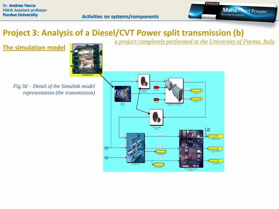
Project 3: Analysis of a Diesel/CVT Power split transmission (b)
The simulation model
Activities on systems/components
Fig 3d – Detail of the Simulink model
representation (the transmission)
(d)
a project completely performed at the University of Parma, Italy

Dr. Andrea VaccaMAHA Assistant professorPurdue University
Project 3: Analysis of a Diesel/CVT Power split transmission (c)
Some results
Activities on systems/components
0.0 0.2 0.4 0.6 0.8 1.0
u/umax
To
tal
tra
ns
mis
sio
n e
ffic
ien
cy
Experimental
Numerical
34
B
1
A
2
max
min
Gear shift
Maximum efficiency
Fig. 3e – Predicted and measured total transmission
efficiency vs tractor speed (in first and second gear)
0.80
0.85
0.90
0.95
1.00
1500 1600 1700 1800 1900 2000 2100 2200
Engine speed [rpm]
η /
η m
ax
H
2050 r/min
Fig. 3f – Individuation of the optimal
operating point
•The model utilizes a significant amount of experimental data for simulating the real performance of both the hydrostatic units and the Diesel engine.•The optimum operating point (minimum fuel consumption) can be predicted for different duties
Final remarks
For more details..• write to [email protected]; [email protected] • see published papers:- Casoli, P., Vacca, A., Berta, G.L., Meleti, S., Vescovini, M., 2007, A Numerical Model for the Simulation of Diesel/CVT
Power Split Transmission, ICE2007 – 8th SAE Int. Conf. on Engines for Automobile, September 16-20, Capri (NA), Italy.
a project completely performed at the University of Parma, Italy

Dr. Andrea VaccaMAHA Assistant professorPurdue University
Project 4: Analysis, design, optimization of power supply systems (a)
•Study and improvement of system controllability•Improvement of system efficiency•Analysis of new ideas (electro-hydraulic control of RV2)
Goals
Project 4.1: discrete variable flow rate supply group
Activities on systems/components
Fig 4a – Schematic of a non optimized variable
displacement (2 level) supply group
Fig 4b – Example of
implementation
a project completely performed at the University of Parma, Italy

Dr. Andrea VaccaMAHA Assistant professorPurdue University
Project 4: Analysis, design, optimization of power supply systems (b)
•Detailed simulation model of the each element of the system
Approach of analysis
Project 4.1: discrete variable flow rate supply group
Activities on systems/components
•Model validation
Fig 4c – The AMESim model of
one of the considered alternatives
Fig 4d –
Comparison
between simulation
results and
experimental data
a project completely performed at the University of Parma, Italy

Dr. Andrea VaccaMAHA Assistant professorPurdue University
Project 4: Analysis, design, optimization of power supply systems (c)
•Work in progress. High potentials of improvement of system behavior•Simulation model already utilized to dimension the internal components
Final remarks
Project 4.1: discrete variable flow rate supply group
Activities on systems/components
For more details..write to [email protected]
a project completely performed at the University of Parma, Italy
Dr. Andrea VaccaMAHA Assistant professorPurdue University
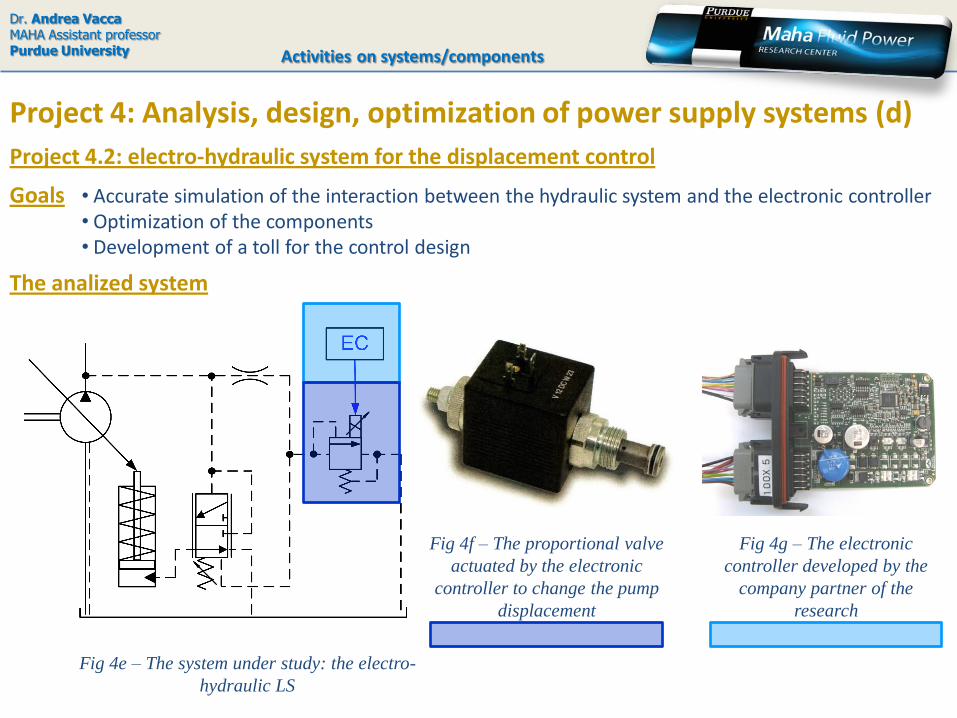
Project 4: Analysis, design, optimization of power supply systems (d)
• Accurate simulation of the interaction between the hydraulic system and the electronic controller• Optimization of the components• Development of a toll for the control design
Goals
Activities on systems/components
Project 4.2: electro-hydraulic system for the displacement control
The analized system
Fig 4e – The system under study: the electro-
hydraulic LS
Fig 4f – The proportional valve
actuated by the electronic
controller to change the pump
displacement
Fig 4g – The electronic
controller developed by the
company partner of the
research
Dr. Andrea VaccaMAHA Assistant professorPurdue University
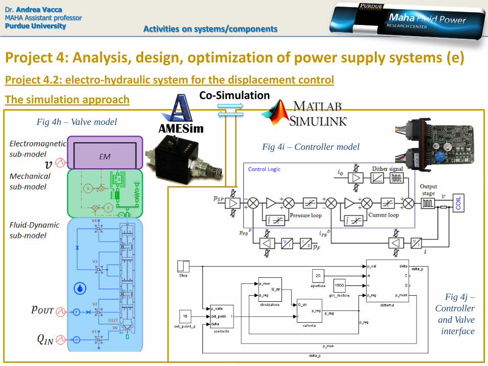
Project 4: Analysis, design, optimization of power supply systems (e)
Activities on systems/components
Project 4.2: electro-hydraulic system for the displacement control
Co-SimulationThe simulation approach
Fig 4i – Controller model
Fig 4h – Valve model
Fig 4j –
Controller
and Valve
interface

Dr. Andrea VaccaMAHA Assistant professorPurdue University
Project 4: Analysis, design, optimization of power supply systems (e)
The simulation approach
Activities on systems/components
Project 4.2: electro-hydraulic system for the displacement control
Fig 4k – The model
of proportional
valve
Fig 4l –
Representation of
the fluid dynamic
model of the valve
Fig 4m –
Electromagnetic
submodel, accounting
for transient effects
(accounting hysteresis,
eddy currents)
0.25 0.5 0.75 1 1.25 1.50
0.2
0.4
0.6
0.8
1
Current i [A]
FEAmodel
Experimental imin
, imax
Experimental imax
, imin
FMA
/FREF
Stroke=2.5mmStroke=0.7mm
Fig 4n – Magnetic flux
resulting from the FEEM
3D simulation model
(CEDRAT FLUX 3D)
Fig 4o – Experimental
validation of Magnetic
force calculated by the
FEEM 3D simulation
model
Dr. Andrea VaccaMAHA Assistant professorPurdue University
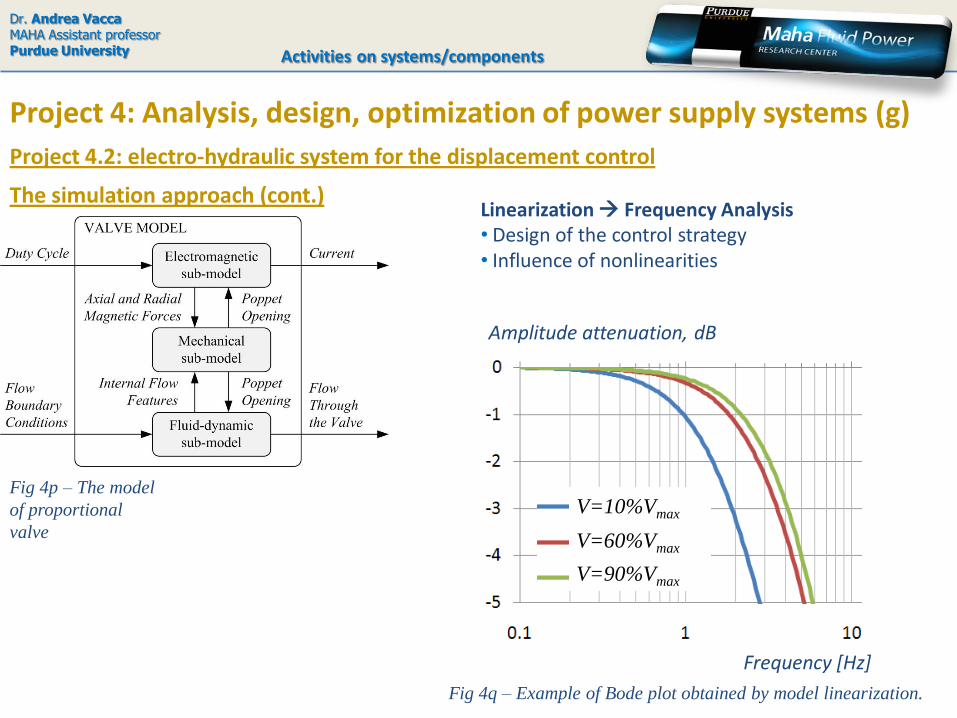
Project 4: Analysis, design, optimization of power supply systems (g)
The simulation approach (cont.)
Activities on systems/components
Project 4.2: electro-hydraulic system for the displacement control
Fig 4p – The model
of proportional
valve
Linearization Frequency Analysis• Design of the control strategy• Influence of nonlinearities
V=10%Vmax
V=60%Vmax
V=90%Vmax
Frequency [Hz]
Amplitude attenuation, dB
Fig 4q – Example of Bode plot obtained by model linearization.

Dr. Andrea VaccaMAHA Assistant professorPurdue University
Project 4: Analysis, design, optimization of power supply systems (h)
Experimental validation of the valve model
Activities on systems/components
Project 4.2: electro-hydraulic system for the displacement control

Dr. Andrea VaccaMAHA Assistant professorPurdue University
Project 4: Analysis, design, optimization of power supply systems (h)
Experimental validation of the valve model
Activities on systems/components
Project 4.2: electro-hydraulic system for the displacement control
Fig 4r – Circuit taken as reference to test the
effect of different control strategies
Fig 4s – Details of effects
(time domain) of a selected control strategy

Dr. Andrea VaccaMAHA Assistant professorPurdue University
Project 4: Analysis, design, optimization of power supply systems (l)
Conclusions – Final Remarks
Activities on systems/components
Project 4.2: electro-hydraulic system for the displacement control
•A very accurate non-linear simulation model for the proportional valve has been developed•The integration between the non linear hydraulic system – electronic controller permits toinvestigate the effects of different control strategies
For more details..• write to [email protected] • see published papers:- Cristofori D., Vacca A., 2010, Analysis of the Dynamics of a Proportional Valve operated by an Electronic Controller, 6th
FPNI PhD Symposium June 15-19, 2010 , West Lafayette IN, USA.
- Vacca A., Cristofori D., 2010, The Modelling of Electro-Hydraulic Proportional Valves, submitted to Int. Journal for Fluid
Power.

Dr. Andrea VaccaMAHA Assistant professorPurdue University
Project 5: Design of a LS flow divider valve (a)
Activities on systems/components
Goals•Development of an accurate model for a flow divider valve utilized in hydraulic power steering system power steering • Reduction of losses and of interdependence between the primary port and secondary port
Typical example of application
Fig 5a – Typical example of
application of the considered valve
Fig 5b – The valve
IN: input
CF: primary outlet port
EF: secondary outlet port
LS: load sensing signal
a project completely performed at the University of Parma, Italy
Dr. Andrea VaccaMAHA Assistant professorPurdue University
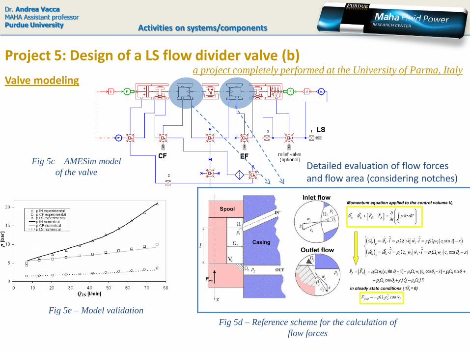
Project 5: Design of a LS flow divider valve (b)
Activities on systems/components
Valve modeling
Detailed evaluation of flow forces and flow area (considering notches)
Fig 5d – Reference scheme for the calculation of
flow forces
Fig 5e – Model validation
a project completely performed at the University of Parma, Italy
Fig 5c – AMESim model
of the valve

Dr. Andrea VaccaMAHA Assistant professorPurdue University
Project 5: Design of a LS flow divider valve (c)
Activities on systems/components
Design optimization
Fig 5f – Parameters considered
Objective functions:1. Flow rate on primary port independent from load, QIN
2. Power losses through secondary port3. Independence of pressure peaks during transients
6 x 32 = 192 conditionsfor the screening analysis
automatic procedure
Fig 5g – Parameters
affecting one of the
objective functions
(normal probability plot)
Investigation procedure by means of Design of Experiments (DOE)
a project completely performed at the University of Parma, Italy
Dr. Andrea VaccaMAHA Assistant professorPurdue University
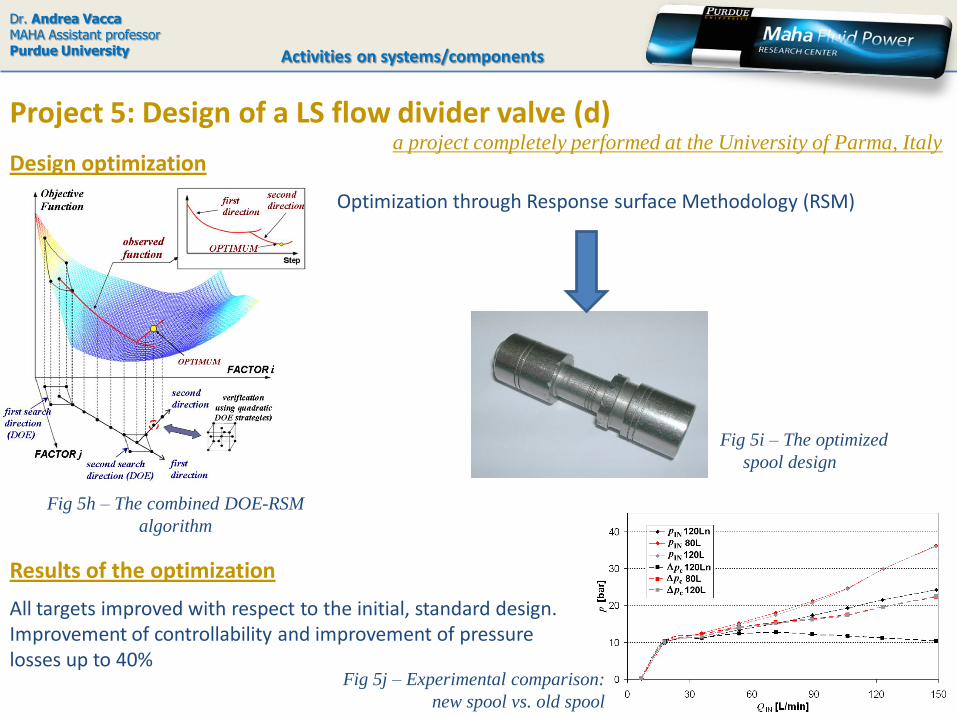
Project 5: Design of a LS flow divider valve (d)
Activities on systems/components
Design optimization
Optimization through Response surface Methodology (RSM)
Fig 5h – The combined DOE-RSM
algorithm
Fig 5i – The optimized
spool design
Results of the optimization
All targets improved with respect to the initial, standard design.Improvement of controllability and improvement of pressure losses up to 40%
Fig 5j – Experimental comparison:
new spool vs. old spool
a project completely performed at the University of Parma, Italy

OBJECTIVE FUNCTIONS
SYSTEM
MODELINPUT
PARAMETERS
Project 5: Design of a LS flow divider valve (e)
Design optimization
Initial DOE created by SOBOL methodOptimization by MOGA II algorithm Evaluation of 1280 designs
Dr. Andrea VaccaMAHA Assistant professorPurdue University Activities on systems/components
a project completely performed at the University of Parma, Italy
Recent application of a optimization procedure specifically multi-objective
Fig 5k – optimization workflow
Fig 5l – pareto frontier
for design selection

Dr. Andrea VaccaMAHA Assistant professorPurdue University
Project 5: Design of a LS flow divider valve (f)
Activities on systems/components
Valve testing
Fig 5m – Apparatus for dynamic test
on the valve (reproduction of sudden
pressure peaks)
Fig 5n – Reproduction of a complete
power steering system for repetitive
measurements
a project completely performed at the University of Parma, Italy

Dr. Andrea VaccaMAHA Assistant professorPurdue University
Project 5: Design of a LS flow divider valve (g)
Activities on systems/components
Conclusions – Final Remarks
• Detailed simulation model: evaluation of flow forces in spool valves• Valve optimization: development of an automatic algorithm that minimize the simulation time
by means of a combined RSM-DOE procedure•Advance valve testing for steady state and transient (realistic) conditions
For more details..• write to [email protected] • see published papers:- Casoli, P., Vacca, A., Franzoni, G., 2003, A numerical model for simulation of “load sensing” spool valves, The 18th
International Conference on Hydraulics and Pneumatics, Prague, Czech Republic, September 30 – October 1, 2003
-Vacca, A. 2006, Proposal of a Load Sensing Two-Way Valve Model, Applying “Design Of Experiments” Techniques to
Simulations, IMECE2006, 2006 ASME International Mechanical Engineering Congress and Exposition, November 2006,
Chicago, Illinois, USA
-Vacca, A., Cerutti, M., 2007, Analysis and Optimization of a Two-Way Valve Using Response Surface Methodology,
International Journal of Fluid Power, Vol. 8, N. 3, November 2007, pp. 43-59
a project completely performed at the University of Parma, Italy
Dr. Andrea VaccaMAHA Assistant professorPurdue University Activities on systems/components
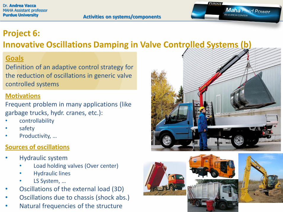
MotivationsFrequent problem in many applications (like garbage trucks, hydr. cranes, etc.):• controllability• safety • Productivity, …
Sources of oscillations
• Hydraulic system• Load holding valves (Over center)• Hydraulic lines• LS System, …
• Oscillations of the external load (3D)• Oscillations due to chassis (shock abs.)• Natural frequencies of the structure
GoalsDefinition of an adaptive control strategy for the reduction of oscillations in generic valve controlled systems
Project 6: Innovative Oscillations Damping in Valve Controlled Systems (b)
Dr. Andrea VaccaMAHA Assistant professorPurdue University Activities on systems/components
Project 6: Innovative Oscillations Damping in Valve Controlled Systems (b)
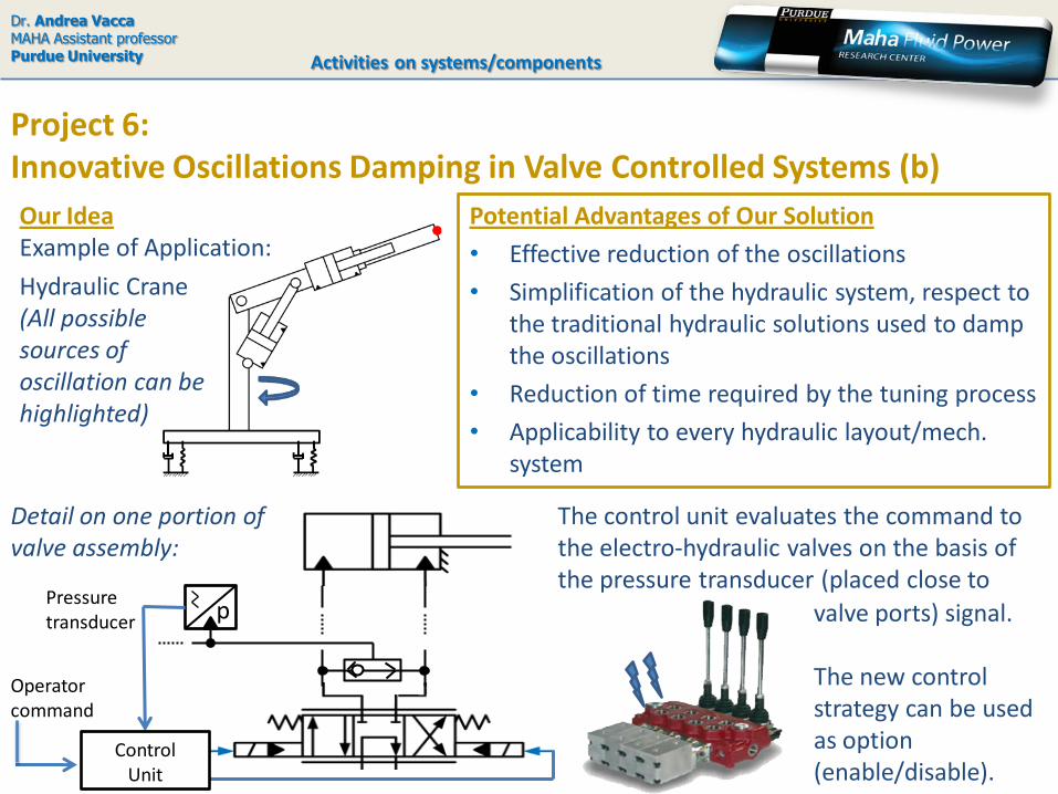
Potential Advantages of Our Solution
• Effective reduction of the oscillations
• Simplification of the hydraulic system, respect to the traditional hydraulic solutions used to damp the oscillations
• Reduction of time required by the tuning process
• Applicability to every hydraulic layout/mech. system
Our IdeaExample of Application:
Operator command
Pressure transducer p
ControlUnit
Detail on one portion of valve assembly:
Hydraulic Crane(All possible sources of oscillation can be highlighted)
The control unit evaluates the command to the electro-hydraulic valves on the basis of the pressure transducer (placed close to
valve ports) signal.
The new control strategy can be used as option (enable/disable).

Dr. Andrea VaccaMAHA Assistant professorPurdue University Activities on systems/components
Project 6: Innovative Oscillations Damping in Valve Controlled Systems (b)
Our IdeaThe control strategy
FILTERS
Example of ESC for one-variable system
Simplified sketch of the control strategy
Extremum Seeking Control (ESC)
GAIN SCHEDULING
or
EXTREMUM SEEKING
CONTROL • Adaptive control strategy, to allow the use of the solution to generic cases
• Solution suitable for standard hydraulic layouts and advanced independent metering system as well
What’s New?

Dr. Andrea VaccaMAHA Assistant professorPurdue University
Project 6: Adaptive control for the cancellation of low freq. disturbances (c)
Activities on systems/components
Modelling approach
Co-Simulation
• Simulation model representative of a real system
• Reference machine: hydraulic crane for trucks
• The plant model (AMESim®) includes the hydr. system, the mech. system and is targeted to describe all possible sources of load oscillation
• The controller model (Simulink®) runs in co-simulation with the plant model
• Phenomenological non linear modeling
• Realistic structure stiffness
• Complete hydraulics modeling

Dr. Andrea VaccaMAHA Assistant professorPurdue University
Project 6: Adaptive control for the cancellation of low freq. disturbances (d)
Activities on systems/components
Under development
• numerical model completion• evaluation of the alternatives control strategies• building a test rig for experimental confirmation
For more details..
• write to [email protected]
Summary
• Definition of the reference system: Hydraulic crane
• Mechanical Structure: chassis with shock absorbers
• Hydraulic System:
• Standard (LS)
• Independent metering
• Definition of the control strategy:
Extremum Seeking vs. Gain Scheduling
• System modeling:
AMESim® - Simulink® co-simulation
• System testing:
Installation of the crane at MAHA (Purdue University)