Embed Size (px)
Citation preview
Title:
Authors:
Source:
Document Type:
Subject Terms:
Abstract:
Full Text Word Count:
ISSN:
Accession Number:
Database:
Record: 1
Rescue challenge: Moving heavy objects.
Brown, Michael G.
Fire Engineering. Aug99, Vol. 152 Issue 8, p93. 9p. 2 Black and WhitePhotographs, 2 Diagrams.
Article
*LIFTING & carrying (Human mechanics)*EQUIPMENT & supplies*SIMPLE machines*RESCUE work
Discusses the use of simple machines to lift heavy objects in rescue workfor fire fighters. Safety tips prior to an obstacle course; Team work andcommunication during the work; Skills needed for the task. INSETS:Rescue challenge '99;Simple machine primer.
5274
00152587
2216220
Academic Search Complete
RESCUE CHALLENGE: MOVING HEAVY OBJECTS
Modern firefighters and rescuers have become spoiled with all of the modern marvels at our disposal. Herculeanhydraulic tools make child's play out of the hardened steel components in today's automobiles. Pneumatic heavylifting bags make short work of lifting a 72,000pound slab of concrete. Electric and gaspowered reciprocatingand chain saws can reduce almost anything to rubble in a matter of minutes. Hydraulic winches are capable oflifting a lane of interstate into place in a single bound. But what do we do when our precious tools don't work,won't fit, can't run, or otherwise are not suitable for the task at hand? Are our RIT and rescue teams proficient atusing simple hand tools, some muscle, and their brains to extricate firefighters and other victims from the horrorsof entrapment when our usual fancy tools don't, won't, or can't handle the job?
THE "O" COURSEAncient technology is being revisited through the obstacle course, or "O" course, one of the finest and mostexciting team integrity building events ever and a highlight of the Federal Emergency Management Agency's(FEMA) Rescue Technician program. It was initiated during the first Rescue Challenge in Henrico, Virginia, in1995 (see sidebar "Rescue Challenge '99" on page 102 for highlights of this year's event).
Basically, the course can be set up almost anywhere, and its costs are very low because of its "backtobasics"technology. The "O" course is designed to teach the fundamentals of lifting and moving heavy objects using onlysimple machines. Understanding the physics, gravity, and friction involved; seeing the effects of these laws on aheavy object or mass; and experiencing the resulting multiplication of power derived from the smart use of simplemachines make the "O" course uniquely educational, exciting, realistic, and just good old hardworking fun.
To begin, a cache of simple tools including a backhoe or track loader; highway barriers; concrete slabs; woodtimbers, wedges, and cribs; steel pipes; lifting chains; rope; chain saws; pipe; pickets; and spray paint must begathered and arranged in an orderly fashion near the "O" course site. A suitable mass (usually called "Big Mo" or
some other suitable personification denoting large size) is brought to the site and becomes the focus of the event.Typically reinforced concrete makes the best Big Mo, but a boulderor even a large steel Ibeamcan be used.Several different types and weights of Big Mo should be available on the site. The evolutions start with lightweights and simple shapes and progress to heavier weights and more complicated configurations.
Jersey (highway) barriers are really cheap, especially if they have been dropped and broken. The advantage ofslabs is that they have an extremely low center of gravity and, therefore, it's unlikely that they will tip over or crushsomeone. Reinforced concrete weighs about 150 pounds per cubic foot. A slab made from a 6foot X 8foot x 6inch form will weigh about 3,600 pounds. Just under two tons is a good weight for teams just getting started inlearning the ancient techniques of moving heavy objects. Our Egyptian mentors easily moved weights 20 timesthe measly two tons. Cubes are very interesting to move. Because of their relatively high center of gravity, theypresent some unique challenges for the teams. Teams can graduate to four and five tons as their knowledge andskill progress. Smart firefighters and rescuers need to have a basic understanding of simple machines to moveheavy objects without the benefit of fancy hydraulic, pneumatic, or electric devices (see "Simple Machine Primer"on page 104).
COURSE DESIGNThe course is designed with a number of obstacles, which keep the course interesting and require the mastery ofmany simple machines. Once the teams get organized and learn a few tricks about moving Big Mo, the exercisegoes more quickly and soon becomes too easy.
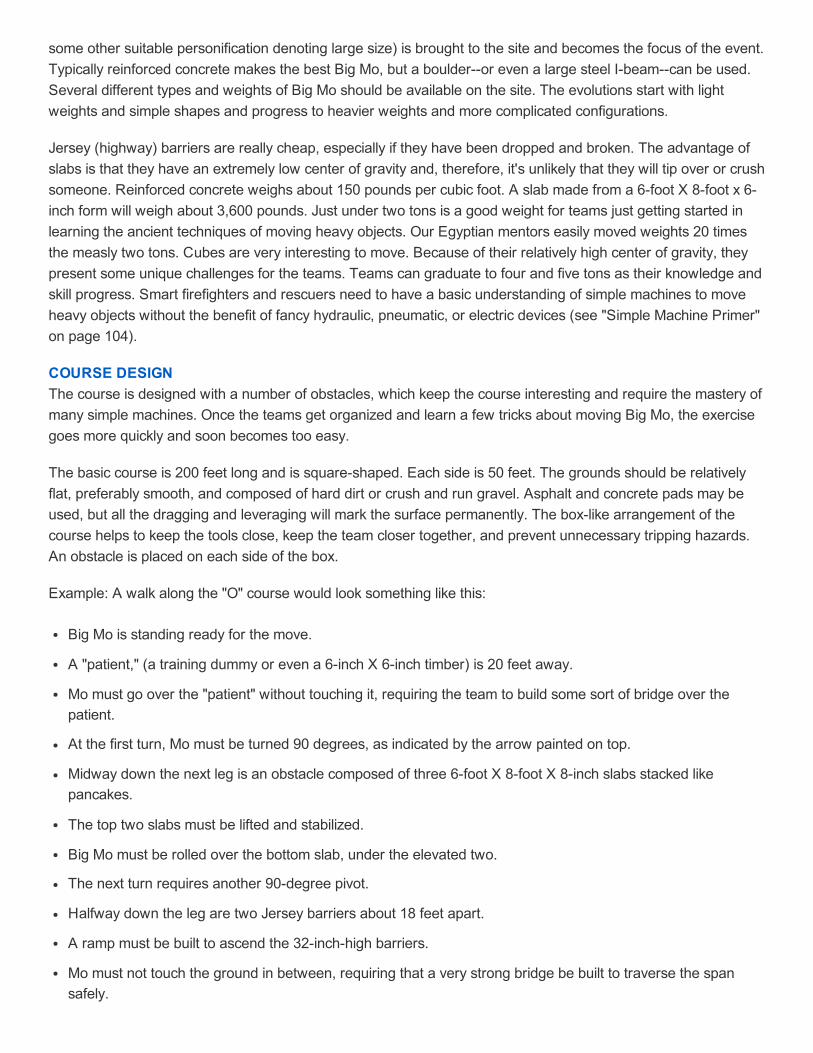
The basic course is 200 feet long and is squareshaped. Each side is 50 feet. The grounds should be relativelyflat, preferably smooth, and composed of hard dirt or crush and run gravel. Asphalt and concrete pads may beused, but all the dragging and leveraging will mark the surface permanently. The boxlike arrangement of thecourse helps to keep the tools close, keep the team closer together, and prevent unnecessary tripping hazards.An obstacle is placed on each side of the box.
Example: A walk along the "O" course would look something like this:
Big Mo is standing ready for the move.
A "patient," (a training dummy or even a 6inch X 6inch timber) is 20 feet away.
Mo must go over the "patient" without touching it, requiring the team to build some sort of bridge over thepatient.
At the first turn, Mo must be turned 90 degrees, as indicated by the arrow painted on top.
Midway down the next leg is an obstacle composed of three 6foot X 8foot X 8inch slabs stacked likepancakes.
The top two slabs must be lifted and stabilized.
Big Mo must be rolled over the bottom slab, under the elevated two.
The next turn requires another 90degree pivot.
Halfway down the leg are two Jersey barriers about 18 feet apart.
A ramp must be built to ascend the 32inchhigh barriers.
Mo must not touch the ground in between, requiring that a very strong bridge be built to traverse the spansafely.
The next turn requires an additional 90degree rotation for the short trip homeexcept that one more obstacleis in the way.
Mo must be airborne over this 18inch "patient." Air must be underneath the twoton cube.
Finally, Mo is brought back to home base and rotated. The evolution is ended. Most teams should be able tocomplete this evolution in about two hours, three hours maximum.
HOW IT'S DONEFour primary factorsteamwork, ingenuity, muscle, and some simple toolsmust be melded into a harmoniousunion to move heavy objects through the "O" course. Moving a heavy object is extremely hazardous work. A tinyslip is all it takes to crush a finger or snap a bone, or worse. As heavy objects are raised into the air, the center ofgravity is also raised, making the objects much more unstable.
The following safety tips should be considered for all (staff included) working on an "O" course:
Wear helmets, gloves, steeltoed boots, and eye protection.
Wear lower back supports.
Plan for mandatory brief rehab and hydration periods.
Always dedicate a safety officer whose only job is to anticipate safety problems and correct them beforesomething undesirable happens.
Any team member should use the "keyword" STOP! anytime. This is an excellent safety tool for any rescueevolution. Some teams use the colloquialism "HO!" or "WHOA" to cease action during training. This practicecan be dangerous because HO and WHOA sound much like GO during the heat and noise of the moment. Ateam tugging on a rope attached to Big Mo 50 feet away may start pulling (GO) when they need to bestopping (WHOA), causing catastrophic results at a critical moment.
Always consider that the weight is going to fall at any moment. Treat Mo with the respect something thatweighs 4,000 pounds deserves. Stay out of its way at all times. If a timber breaks or a crib tower crumbles, theobject can fall safely onto the groundno big deal!
Always have an escape path in case you have to back away. Team members tend to focus a lot on the objectbeing worked on and forget to keep a clear path of retreat. Keep all trip hazards (including other teammembers) away from your path of escape.
With all lifting operations, if you lift an inch, crib an inch. Make sure your crib towers start out wide with railroadtiesized cribbing, and as you tower up, move onto 8 x 8inch crib blocks, to 6 x 6inch, down to 4 X 4inchcribs as you build up. Never allow a crib tower to be built higher than three times its width, and interlaceadjacent crib towers at least every 18 inches.
Brief your team members on the safety rules, and enforce the authority of the safety officer to stop the event.Review safe lifting practices. Encourage brain over brawn.
The "O" course is a wonderful team builder, as there is simply no way to move four or five thousand pounds ofconcrete without the cooperation and strength of a unified team. It is one training evolution during which no onestands around idle, not if Big Mo is going to be moved safely. When taken seriously, the hazards associated withmoving a 4,000pound piece of concrete around an obstacle course create a sobering adrenaline rush, which, ifchanneled correctly, can enhance a team's performance and add a level of excitement similar to that experienced
in reallife emergencies.
It takes an array of skills working simultaneously to complete the course in a reasonable time. The optimumnumber of team members for working the object around the "O" course efficiently is between 12 and 20. Fewermembers can effectively do the job, but it will take more time. While some teammates are busy preparing for themove by laying 4 x 4 "track," others are busy hauling cribbing to the trislab site, while still others are building theJersey barrier bridge. On command, all hands are required to start the move. Once moving, the whole teamworks at a quick, but safe, pace. Some team members are moving Big Mo with pinch bars or timber levers;others are placing pipes in front of the cube; others are removing pipes that have just been run over andtransferring them to the front; others are rotating track forward; others are watching for safety problems; and, ofcourse, a team leader is working on the strategy well in advance of the object.
Think big. Bridging Jersey barriers or trenches requires big stuff if you are going to lug four or five thousandpounds across it. Ground rails supporting rolling pipe stock may be 4inch x 4inch, but two quality 6inch x 6inchtimbers with cribbing supports every eight feet are the minimum quantity and size of timbers capable ofsupporting the elevated weight with any sense of security.
Don't overload the site with too much equipment. Force the team members to reuse cribbing and timber at eachnew obstacle. There should only be enough equipment available to have two obstacles surmounted at any onetime.
Advanced features can be added to the course for teams that have mastered the basics: A steel railroad track orthe like can be hammered into the ground vertically at the starting point, for example, and Mo can be welded tothe rail, requiring a cutting operation before it will move even an inch. The teams can practice settingfriction/expansion bolts into the concrete by bolting plate steel (for welding points) onto its surface. Even better,the teams must weld an appropriate "eye" onto the plate they bolted, strong enough to lift Mo into the air with anonsite, handbuilt gantry.
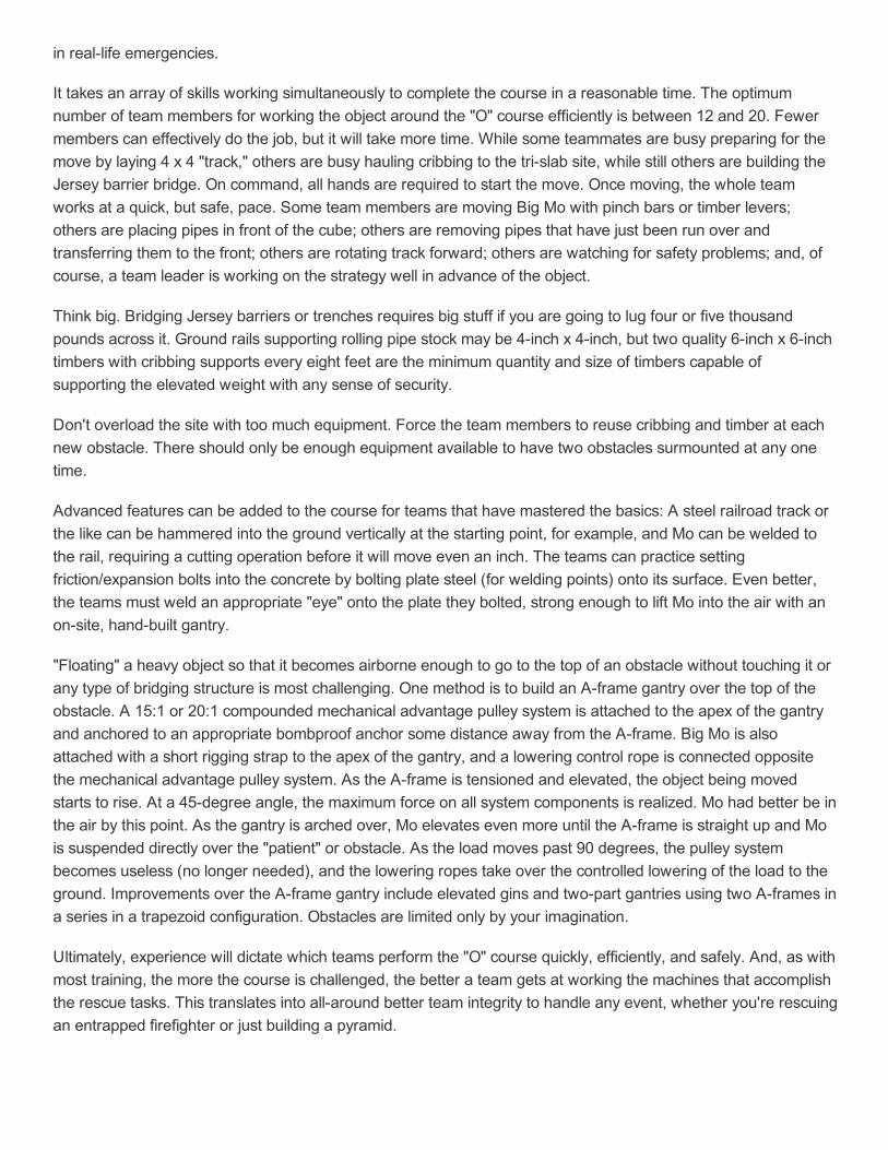
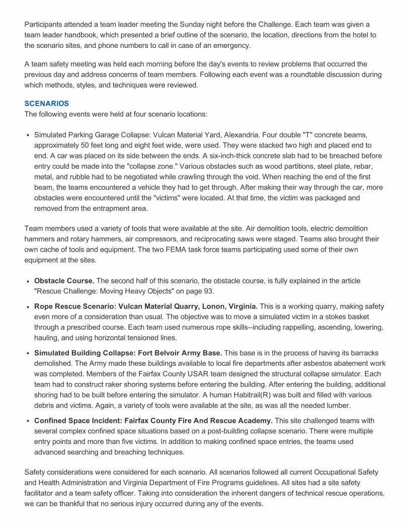
"Floating" a heavy object so that it becomes airborne enough to go to the top of an obstacle without touching it orany type of bridging structure is most challenging. One method is to build an Aframe gantry over the top of theobstacle. A 15:1 or 20:1 compounded mechanical advantage pulley system is attached to the apex of the gantryand anchored to an appropriate bombproof anchor some distance away from the Aframe. Big Mo is alsoattached with a short rigging strap to the apex of the gantry, and a lowering control rope is connected oppositethe mechanical advantage pulley system. As the Aframe is tensioned and elevated, the object being movedstarts to rise. At a 45degree angle, the maximum force on all system components is realized. Mo had better be inthe air by this point. As the gantry is arched over, Mo elevates even more until the Aframe is straight up and Mois suspended directly over the "patient" or obstacle. As the load moves past 90 degrees, the pulley systembecomes useless (no longer needed), and the lowering ropes take over the controlled lowering of the load to theground. Improvements over the Aframe gantry include elevated gins and twopart gantries using two Aframes ina series in a trapezoid configuration. Obstacles are limited only by your imagination.
Ultimately, experience will dictate which teams perform the "O" course quickly, efficiently, and safely. And, as withmost training, the more the course is challenged, the better a team gets at working the machines that accomplishthe rescue tasks. This translates into allaround better team integrity to handle any event, whether you're rescuingan entrapped firefighter or just building a pyramid.
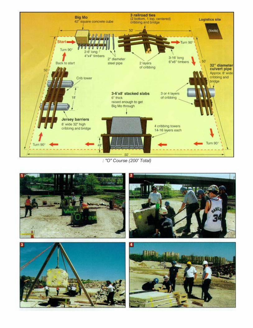
: "O" Course (200' Total)
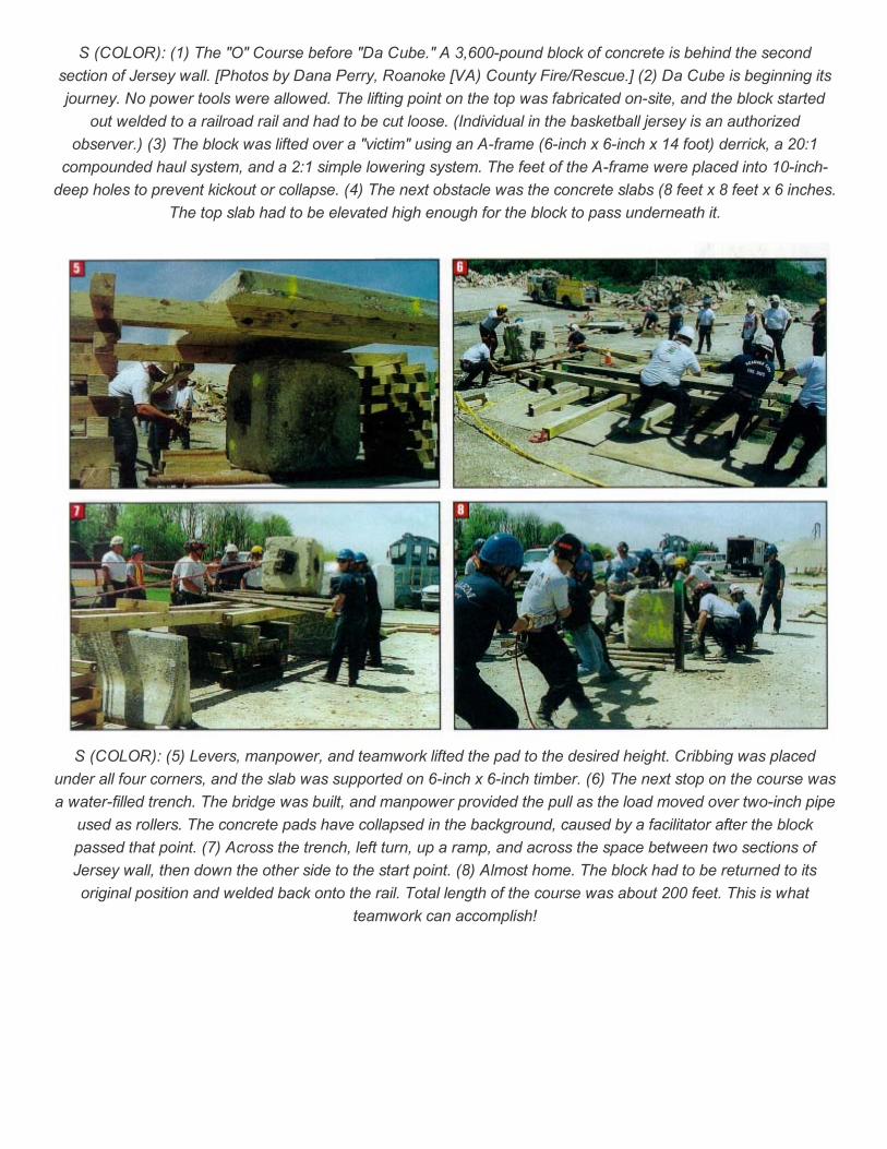
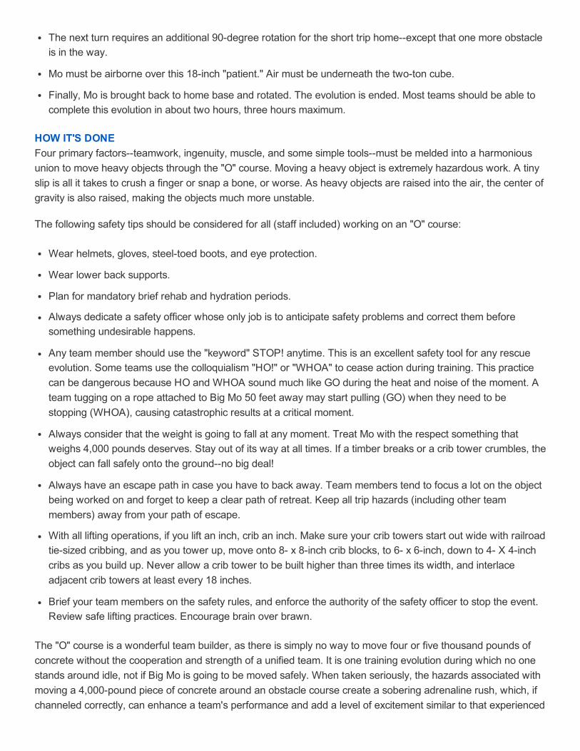
S (COLOR): (1) The "O" Course before "Da Cube." A 3,600pound block of concrete is behind the secondsection of Jersey wall. [Photos by Dana Perry, Roanoke [VA) County Fire/Rescue.] (2) Da Cube is beginning itsjourney. No power tools were allowed. The lifting point on the top was fabricated onsite, and the block started
out welded to a railroad rail and had to be cut loose. (Individual in the basketball jersey is an authorizedobserver.) (3) The block was lifted over a "victim" using an Aframe (6inch x 6inch x 14 foot) derrick, a 20:1
compounded haul system, and a 2:1 simple lowering system. The feet of the Aframe were placed into 10inchdeep holes to prevent kickout or collapse. (4) The next obstacle was the concrete slabs (8 feet x 8 feet x 6 inches.
The top slab had to be elevated high enough for the block to pass underneath it.
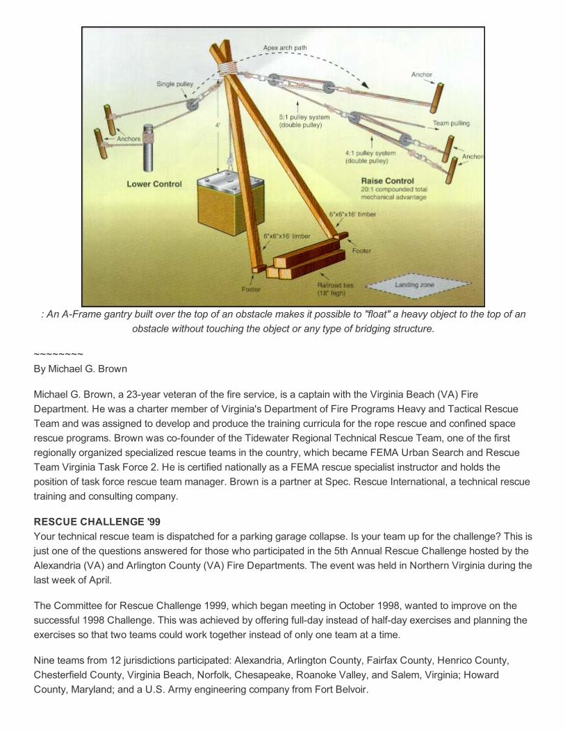
S (COLOR): (5) Levers, manpower, and teamwork lifted the pad to the desired height. Cribbing was placedunder all four corners, and the slab was supported on 6inch x 6inch timber. (6) The next stop on the course wasa waterfilled trench. The bridge was built, and manpower provided the pull as the load moved over twoinch pipe
used as rollers. The concrete pads have collapsed in the background, caused by a facilitator after the blockpassed that point. (7) Across the trench, left turn, up a ramp, and across the space between two sections ofJersey wall, then down the other side to the start point. (8) Almost home. The block had to be returned to itsoriginal position and welded back onto the rail. Total length of the course was about 200 feet. This is what
teamwork can accomplish!
: An AFrame gantry built over the top of an obstacle makes it possible to "float" a heavy object to the top of anobstacle without touching the object or any type of bridging structure.
~~~~~~~~By Michael G. Brown
Michael G. Brown, a 23year veteran of the fire service, is a captain with the Virginia Beach (VA) FireDepartment. He was a charter member of Virginia's Department of Fire Programs Heavy and Tactical RescueTeam and was assigned to develop and produce the training curricula for the rope rescue and confined spacerescue programs. Brown was cofounder of the Tidewater Regional Technical Rescue Team, one of the firstregionally organized specialized rescue teams in the country, which became FEMA Urban Search and RescueTeam Virginia Task Force 2. He is certified nationally as a FEMA rescue specialist instructor and holds theposition of task force rescue team manager. Brown is a partner at Spec. Rescue International, a technical rescuetraining and consulting company.
RESCUE CHALLENGE '99 Your technical rescue team is dispatched for a parking garage collapse. Is your team up for the challenge? This isjust one of the questions answered for those who participated in the 5th Annual Rescue Challenge hosted by theAlexandria (VA) and Arlington County (VA) Fire Departments. The event was held in Northern Virginia during thelast week of April.
The Committee for Rescue Challenge 1999, which began meeting in October 1998, wanted to improve on thesuccessful 1998 Challenge. This was achieved by offering fullday instead of halfday exercises and planning theexercises so that two teams could work together instead of only one team at a time.
Nine teams from 12 jurisdictions participated: Alexandria, Arlington County, Fairfax County, Henrico County,Chesterfield County, Virginia Beach, Norfolk, Chesapeake, Roanoke Valley, and Salem, Virginia; HowardCounty, Maryland; and a U.S. Army engineering company from Fort Belvoir.
Participants attended a team leader meeting the Sunday night before the Challenge. Each team was given ateam leader handbook, which presented a brief outline of the scenario, the location, directions from the hotel tothe scenario sites, and phone numbers to call in case of an emergency.
A team safety meeting was held each morning before the day's events to review problems that occurred theprevious day and address concerns of team members. Following each event was a roundtable discussion duringwhich methods, styles, and techniques were reviewed.
SCENARIOSThe following events were held at four scenario locations:
Simulated Parking Garage Collapse: Vulcan Material Yard, Alexandria. Four double "T" concrete beams,approximately 50 feet long and eight feet wide, were used. They were stacked two high and placed end toend. A car was placed on its side between the ends. A sixinchthick concrete slab had to be breached beforeentry could be made into the "collapse zone." Various obstacles such as wood partitions, steel plate, rebar,metal, and rubble had to be negotiated while crawling through the void. When reaching the end of the firstbeam, the teams encountered a vehicle they had to get through. After making their way through the car, moreobstacles were encountered until the "victims" were located. At that time, the victim was packaged andremoved from the entrapment area.
Team members used a variety of tools that were available at the site. Air demolition tools, electric demolitionhammers and rotary hammers, air compressors, and reciprocating saws were staged. Teams also brought theirown cache of tools and equipment. The two FEMA task force teams participating used some of their ownequipment at the sites.
Obstacle Course. The second half of this scenario, the obstacle course, is fully explained in the article"Rescue Challenge: Moving Heavy Objects" on page 93.
Rope Rescue Scenario: Vulcan Material Quarry, Lonon, Virginia. This is a working quarry, making safetyeven more of a consideration than usual. The objective was to move a simulated victim in a stokes basketthrough a prescribed course. Each team used numerous rope skillsincluding rappelling, ascending, lowering,hauling, and using horizontal tensioned lines.
Simulated Building Collapse: Fort Belvoir Army Base. This base is in the process of having its barracksdemolished. The Army made these buildings available to local fire departments after asbestos abatement workwas completed. Members of the Fairfax County USAR team designed the structural collapse simulator. Eachteam had to construct raker shoring systems before entering the building. After entering the building, additionalshoring had to be built before entering the simulator. A human Habitrail(R) was built and filled with variousdebris and victims. Again, a variety of tools were available at the site, as was all the needed lumber.
Confined Space Incident: Fairfax County Fire And Rescue Academy. This site challenged teams withseveral complex confined space situations based on a postbuilding collapse scenario. There were multipleentry points and more than five victims. In addition to making confined space entries, the teams usedadvanced searching and breaching techniques.
Safety considerations were considered for each scenario. All scenarios followed all current Occupational Safetyand Health Administration and Virginia Department of Fire Programs guidelines. All sites had a site safetyfacilitator and a team safety officer. Taking into consideration the inherent dangers of technical rescue operations,we can be thankful that no serious injury occurred during any of the events.
Rescue Challenge 2000 will move to the Roanoke Valley area of Virginia, where it will be held for two years.Participants will be offered a vast array of new and challenging scenarios.
LESSONS LEARNEDIn the two years that Northern Virginia has hosted the Rescue Challenge, we have learned much.
You must plan early.
It is important to develop good working relationships with private industry.
Anticipating the unexpected can make your ask much easier.
Logistical needs such as tools, maps, food, comfort facilities, and communication equipment are critical.
Each site must have its own logistical support person to handle equipment problems that may arise.
Communications between sites are vital. Cellular phones and radios were provided at each site.
Teamwork and flexibility are needed to make events such as this one successful.
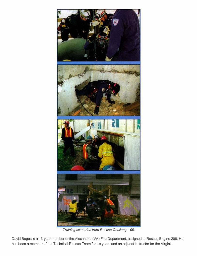
Training scenarios from Rescue Challenge '99.
David Bogos is a 13year member of the Alexandria (VA) Fire Department, assigned to Rescue Engine 206. Hehas been a member of the Technical Rescue Team for six years and an adjunct instructor for the Virginia
Department of Fire Programs since 1975
Kenneth E. Salfelder, a member of the fire service since 1975, has spent the past 15 years in the Alexandria (VA)Fire Department, where he is assigned to Rescue Engine 206. He has been a member of the Technical RescueTeam for 10 years and is a statecertified fire instructor.
SIMPLE MACHINE PRIMER Simple machines perform their work in a single movement. Some simple machines are inclined planes [ramps,wheel chocks, screw jacks (inclined planes on a helix), propellers, interstate "on" ramps, wedges, stairs, and thelike]; levers (pinch bars, teetertotters, shovels, light switches, pipes, rods, and long timbers); pulleys [wheels,trolleys (rolls along a rope or cable)]; and carriages (rolls on a surface).
All of these simple machines take advantage of the mechanical physics law "Conservation of Mechanical Energy."Essentially, the amount of effort or energy required to move an object is called "work." The same amount of workis required to move an object no matter how you move it. Simple machines allow us to spread the work out over agreater time and distance, using less force than if we tried (unsuccessfully) to move the object without usingsimple machines.
As humans, we have a pretty puny "power window," maybe a couple of hundred pounds, which is not going toremove a twoton slab off an entrapped firefighter. But if a firefighter knew a little about simple machines, hecould free the entrapped firefighter by spreading the lift out over time and distance. An appropriately long timberand a handy fulcrum could lift two tons using the 100 pounds of available power of a single firefighter.
Conservation of Mechanical Energy just means that the work applied by the 200 pounds of force capable of beingdelivered by the firefighter using the simple machine, the lever, equals the amount of work 20 firefighters wouldhave used to lift the slab. Instead of just lifting the slab six inches, the single firefighter had to move the lever 12 ormaybe 15 feet to get the six inches of raise on the slab next to the fulcrum, a much farther distance (and time)than the 20firefighter lift. The total amount of work required is essentially equal.
There is one other little (read "huge") factor that adds to the work required to accomplish a task like moving aheavy objectfriction. Friction occurs whenever two objects rub against each other. It produces heat and robs allmachines of efficiency. All simple, compound, and complex machines develop friction, which makes them lessefficient. In effect, part of the 200 pounds the firefighter can apply to a lever is used up overcoming the effects offriction on the lever. Machines can be classified according to the amount of friction they develop when in use.When measured, it is called the" friction coefficient." Machines that have low friction coefficients have relativelysimilar output to input ratios, meaning the amount of energy put in is close to the amount of energy coming out ofthe machine, a very efficient machine indeed (a machine with a high coefficient of friction eats up much of its inputenergy, and is therefore relatively inefficient). When practical, machines with low friction coefficients should beused.
Inclined Plane
Inclined planes can be envisioned by imagining a fivefoothigh loading dock. Your job is to lift a 500pound boxup onto the dock. Knowing 500 pounds is way outside of your power window, you wisely choose to build a rampsloping up and onto the loading dock. Your ramp is 20 feet long; your rise to the dock is five feet. Theoretically,your inclined plane simple machine is providing you with a 4:1 mechanical advantage (20 divided by 5 = 4).Therefore, the box should only feel like it weighs 125 pounds (500 divided by 4 = 125), except friction is thedifference between theoretical mechanical advantage and actual mechanical advantage. Inclined planes are
notoriously inefficient because of the high amount of surface are contacted by the object being moved. Pushingthe heavy box up a frictionless ramp would be well within your power window; it would just take more time anddistance than just lifting the box up (like Superman) and setting it on the dock. The smart firefighter, therefore,reduces the effects of friction on the ramp and the box by placing rollers (metal pipes, wheels, coasters, grease,and so on) under the box and zipping it right on up the ramp (like in the "O" course).
Lever
Another simple machine, the lever, is a combination of three components: a bar (the lever), a fulcrum, and anapplied force aligned in such a manner as to transmit that force to another object. Levers can be classified asClass I, Class II, or Class III, depending on where the fulcrum, applied force, and lever are placed in relation tothe object being moved.
* Class I lever. The fulcrum is placed somewhere between the object being lifted and the applied force, and thatforce is being applied in a direction opposite the direction of the object being moved. A teetertotter comes tomind as a familiar example. The lever is the teetertotter board; the object being moved is one kid or the other,take your pick; the fulcrum is the board support (cross member to the ground); and the applied force is the otherkid (the one you did not pick to be the object being moved). As the fulcrum is moved closer to one side, more andmore advantage can be gained. A little scrawny kid can lift a monster if the fulcrum is moved very close to themonster, making the lever (leverage) very long for the kid. Specifically, if you have one foot of the lever on oneside of the fulcrum and 10 feet of the lever on the other side of the fulcrum, you have a 10:1 mechanicaladvantage. Theoretically, 100 pounds pushing down on the lever translates to 1,000 pounds applied to the objectbeing lifted. Class I levers benefit infinitely by extending the lever infinitely. Theoretically, you could lift an aircraftcarrier with one finger if you had a lever long (and strong) enough and a fulcrum against which to push.
Drawback: It cannot perform its function repeatedly. The Class I had a stroke (the distance from start of levermovement to finish of lever movement) that is determined by the position of the fulcrum, the object, and the lever.Unless there is something to capture the progress made by the lever, any gain will be lost when the lever returnsto the starting position.
* Class II lever. The fulcrum is on the end of the lever, the object being moved is between the applied force andthe fulcrum, and the applied force is at the end opposite the fulcrum. The force is moving in the some direction asthe object being moved. A wheelbarrow is the classic example. The applied force is the person carrying thehandles, the object being moved is the load in the barrow, the lever is the handles and frame, and the fulcrum isthe axle in the wheel. Again, the mechanical advantage is determined by the relative location of the object beingmoved and the fulcrum. The closer the object being moved is to the fulcrum, the greater the mechanicaladvantage. Additionally, the Class II lever has the potential for a longer stroke, and thus the object can be movedfarther in a single stroke. The practical disadvantage of the Class II is that the lever itself can only be so long as tobecome too lengthy to reach, and much of the mechanical leverage is counteracted by the weight of the lever.
* Class III lever. This lever applies force between the fulcrum and the object being moved. The fulcrum is at oneend of the lever, the object being lifted is at the opposite end, and the applied force and the object move in thesame direction. The best example of a Class III lever is a fire department aerial ladder, where the lever is theladder, the fulcrum is anchored to the turntable, the applied force is from hydraulic cylinders pushing on the bedladder,and the object being moved is the tip of the ladder or platform. No mechanical advantage is gained fromthe Class III lever; in fact, mechanical disadvantage is the result, as the weight of the lever adds weight theapplied force must move, and the disadvantage gets progressively worse as the applied force moves closer to thefulcrum. It is only through the near miracle of shear hydraulic force, delicate balance, and raw outrigger
stabilization that the terrible Class III aerial lifting lever lifts anything at all. But the Class III does have a potentiallylong stroke and is useful in applications where stroke is needed and sufficient force is available to lift the lever andthe object with no additional mechanical advantage.
Pulley
The pulley transfer applied force from one location to another when used in conjunction with a flexible mediumrope, chain, belts, or the like. The round disk in a pulley is called a sheave, the sides are called side plates, andthe device in the center about which the sheave rotates (usually supported by ball bearings) is called the axle.Pulleys with two or three sheaves are called double and triplesheave pulleys, respectively (go figure). Anydouble pulley worth its salt has a center plate and an extension off the center plate for a carabiner attachment,called the becket (some double pulleys do not have beckets, no telling why).
A pulley simply transfers the same amount of force into the sheave (input) as it receives out of the sheave(output), minus any frictional elements, of course. The pulley itself develops zero mechanical advantage, as thefulcrum (axle) is dead center, like a balanced teetertooter.
All pulleys turn on their axles. When used to build a rope system, they are either fixed in position (anchored) ormoving a load. Determining whether a pulley is anchored or moving a load is critical in determining themechanical advantage of a machine and its components, like a rope system.
* Anchored pulleys are directional only and provide no mechanical advantage. Imagine anchoring a pulley to oneof the overhead beams of your station. Reeve a rope through the pulley so both ends of the rope dangle to theground. A changeofdirection pulley arrangement like this has many uses but develops no mechanicaladvantage. In fact, it can be considered a disadvantage because when a load is being pulled up one side by therope being pulled down on the other side, twice as much weight is on the pulley as the load itself. The force ofgravity on the load and the force put on the rope by your pulling down on the other side are added together.
Copyright of Fire Engineering is the property of PennWell Corporation and its content may not be copied oremailed to multiple sites or posted to a listserv without the copyright holder's express written permission.However, users may print, download, or email articles for individual use.