Embed Size (px)
Citation preview
Rerouting Electric Power Transmission Lines by using Satellite Imagery
T. LUEMONGKOL1, A. WANNAKOMOL2 & T. KULWORAWANICHPONG1 1Power System Research Unit, School of Electrical Engineering
2School of Geotechnology Institute of Engineering
Suranaree University of Technology Nakhon Ratchasima 30000, Thailand
Abstract: - This paper presents an application of satellite image technology for rerouting electric power transmission lines. Satellite images produced by using ENVI software were used as our major tool. Information from remote sensing and geographic information system (GIS) can be extracted by using photographs from LANDSAT ETM and topographic map. In this paper, areas of Nakhon Ratchasima province, north-east of Thailand, were examined for a case study. The main objective for rerouting electric power transmission lines is to remove all transmission portions located nearby or passed through a community. Key-Words: - Power transmission line, extra high voltage system, satellite image technology, power system planning 1 Introduction Satellite images have found their several applications [1-5] in fields of agriculture, geology, forestry, biodiversity conservation, regional planning, education, intelligence, warfare, weather forecast, electric power system, etc. Images can be in visible colors and in other spectra. To interpret and analyze satellite images, some efficient software packages like ERDAS or ENVI are necessary. All satellite images produced by NASA are published by Earth Observatory and are freely available to the public. Several other countries, nowadays, have satellite imaging programs, and a collaborative European effort launched the ERS and Envisat satellites carrying various sensors. There are also private companies that provide commercial satellite imagery. In the early 21st century satellite imagery became widely available when affordable, easy to use software with access to satellite imagery databases became offered by several companies and organizations.
For decades, electric power transmission lines, particularly in Thailand, were constructed for linked between power plants and electric power substations across the country. In recent years, population growth forces community expanding its size. Residential areas spread themselves in all direction without any restriction. Several villages in local areas have shifted their border close to or cross with electric transmission lines. One of important work for electric power transmission planning is to reroute existing power
transmission lines to a direction with less community underneath or nearby. This work can be performed by using aerial pictures of the targeted area captured by some flying vehicles like UAVs or helicopters. With availability and accessibility of satellite imaging resources, it is simpler and cheaper to reroute electric power transmission lines with examining associated satellite images. Due to the recent progress of satellite imaging technology, the image resolution of some commercial satellites can reach to less than 1 meter. This resolution is sufficient for the rerouting work mentioned earlier. It is the fact that the total area of the Earth surface is too large and satellite image resolution is relatively high. Satellite databases are huge and image processing, which creates useful images from the raw data, is time-consuming. Depending on the sensor used, weather conditions can affect image quality. For example, it is difficult to obtain images clearly for areas of frequent cloud cover such as mountain-tops. In this paper, Section 2 gave a brief of electric power transmission lines. The tower structure and conductor alignment for electric power transmission systems are summarized in this section. Section 3 illustrated satellite imagery and its applications to some research fields. Topographic maps that were used in this work were also described in this section. Procedure for rerouting the electric transmission line that is the main objective of this paper was also given in this section. The next section, Section 4, provided results of the rerouting scheme proposed in this paper. Section 6, the last
WSEAS TRANSACTIONS on ENVIRONMENT and DEVELOPMENTT. Luemongkol, A. Wannakomol, T. Kulworawanichpong
ISSN: 1790-5079 189 Issue 2, Volume 5, February 2009
section, concluded the results and discussed further for future work. 2 Electric Power Transmission Systems Electric power transmission systems are the systems to deliver electric power to groups of consumers in form of electric power substations. The power transmission systems are connected to power plants through step-up transformers in order to transfer electric energy, from power plants to multiple substations, across the country. The electric power transmission systems can be carried out by means of overhead lines or underground cables [6-8]. The underground systems are rarely used in normal situations due to the two reasons: i) power is transmitted over long distances to loads and ii) the installation cost of the underground system is very expensive. To transmit powers over long distances, a high voltage system of above 110 kV is typically used. Nowadays, with increasing in electrical demands, the power transmission systems are operated at extra high voltage level, 230 kV and above. Although there are many types of transmission towers or poles used for power transmission, steels towers are invariably employed for long distance transmission at higher voltage level.
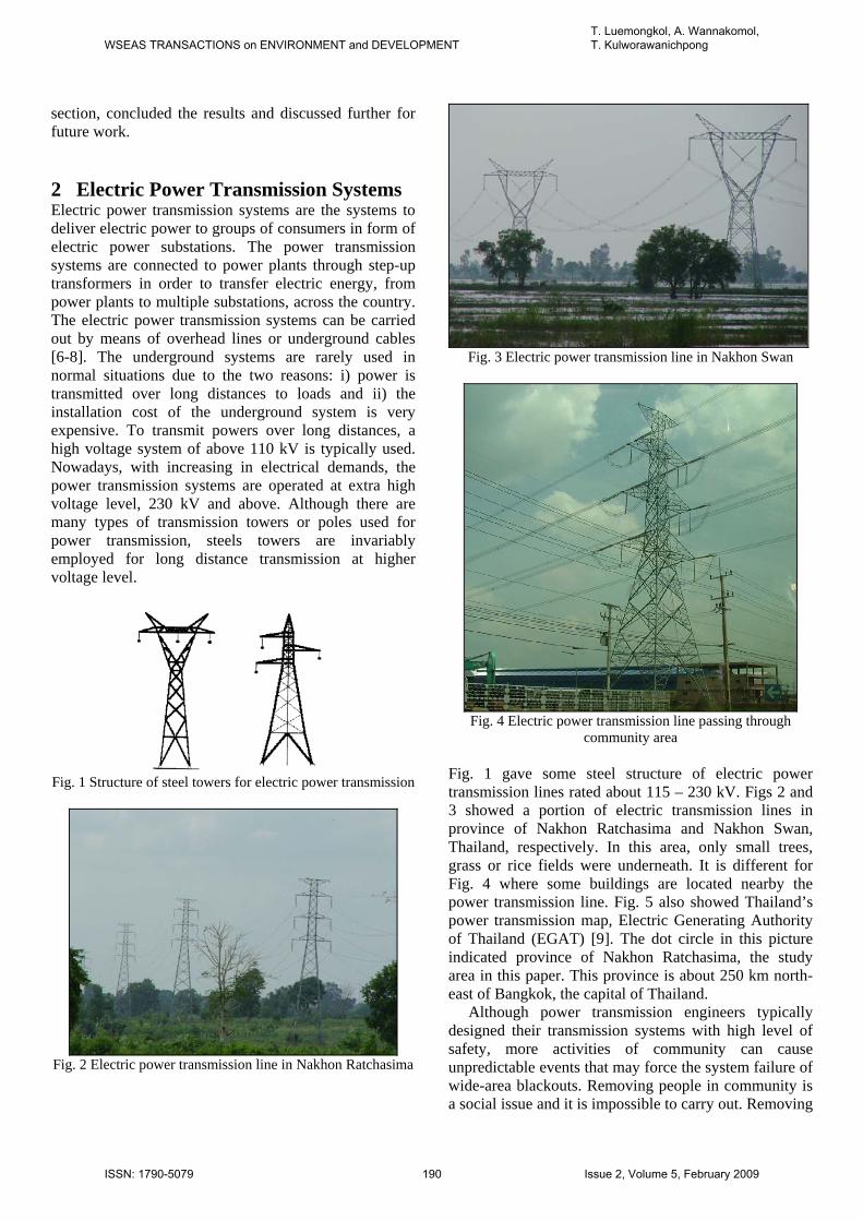
Fig. 1 Structure of steel towers for electric power transmission
Fig. 2 Electric power transmission line in Nakhon Ratchasima
Fig. 3 Electric power transmission line in Nakhon Swan
Fig. 4 Electric power transmission line passing through
community area
Fig. 1 gave some steel structure of electric power transmission lines rated about 115 – 230 kV. Figs 2 and 3 showed a portion of electric transmission lines in province of Nakhon Ratchasima and Nakhon Swan, Thailand, respectively. In this area, only small trees, grass or rice fields were underneath. It is different for Fig. 4 where some buildings are located nearby the power transmission line. Fig. 5 also showed Thailand’s power transmission map, Electric Generating Authority of Thailand (EGAT) [9]. The dot circle in this picture indicated province of Nakhon Ratchasima, the study area in this paper. This province is about 250 km north-east of Bangkok, the capital of Thailand. Although power transmission engineers typically designed their transmission systems with high level of safety, more activities of community can cause unpredictable events that may force the system failure of wide-area blackouts. Removing people in community is a social issue and it is impossible to carry out. Removing
WSEAS TRANSACTIONS on ENVIRONMENT and DEVELOPMENTT. Luemongkol, A. Wannakomol, T. Kulworawanichpong
ISSN: 1790-5079 190 Issue 2, Volume 5, February 2009
the existing transmission lines is a better choice. In addition, rerouting the transmission portion needs investment. Harm to people and power failure may cost more compensation due to the social issues.
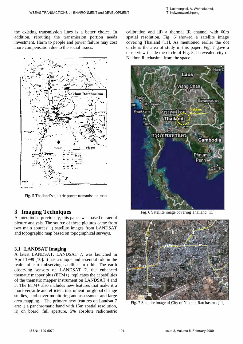
Fig. 5 Thailand’s electric power transmission map
3 Imaging Techniques As mentioned previously, this paper was based on aerial picture analysis. The source of these pictures came from two main sources: i) satellite images from LANDSAT and topographic map based on topographical surveys. 3.1 LANDSAT Imaging A latest LANDSAT, LANDSAT 7, was launched in April 1999 [10]. It has a unique and essential role in the realm of earth observing satellites in orbit. The earth observing sensors on LANDSAT 7, the enhanced thematic mapper plus (ETM+), replicates the capabilities of the thematic mapper instrument on LANDSAT 4 and 5. The ETM+ also includes new features that make it a more versatile and efficient instrument for global change studies, land cover monitoring and assessment and large area mapping. The primary new features on Landsat 7 are: i) a panchromatic band with 15m spatial resolution, ii) on board, full aperture, 5% absolute radiometric
calibration and iii) a thermal IR channel with 60m spatial resolution. Fig. 6 showed a satellite image covering Thailand [11]. As mentioned earlier the dot circle is the area of study in this paper. Fig. 7 gave a close view inside the circle of Fig. 5. It revealed city of Nakhon Ratchasima from the space.
Fig. 6 Satellite image covering Thailand [11]
Fig. 7 Satellite image of City of Nakhon Ratchasima [11]
Nakhon Ratchasima
Nakhon Ratchasima
WSEAS TRANSACTIONS on ENVIRONMENT and DEVELOPMENTT. Luemongkol, A. Wannakomol, T. Kulworawanichpong
ISSN: 1790-5079 191 Issue 2, Volume 5, February 2009
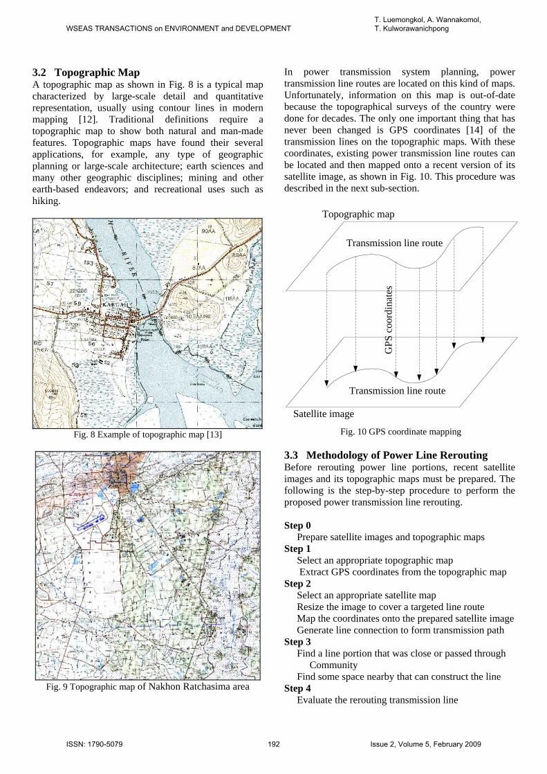
3.2 Topographic Map A topographic map as shown in Fig. 8 is a typical map characterized by large-scale detail and quantitative representation, usually using contour lines in modern mapping [12]. Traditional definitions require a topographic map to show both natural and man-made features. Topographic maps have found their several applications, for example, any type of geographic planning or large-scale architecture; earth sciences and many other geographic disciplines; mining and other earth-based endeavors; and recreational uses such as hiking.
Fig. 8 Example of topographic map [13]
Fig. 9 Topographic map of Nakhon Ratchasima area
In power transmission system planning, power transmission line routes are located on this kind of maps. Unfortunately, information on this map is out-of-date because the topographical surveys of the country were done for decades. The only one important thing that has never been changed is GPS coordinates [14] of the transmission lines on the topographic maps. With these coordinates, existing power transmission line routes can be located and then mapped onto a recent version of its satellite image, as shown in Fig. 10. This procedure was described in the next sub-section.
Topographic map
Satellite image
GPS
coo
rdin
ates
Transmission line route
Transmission line route
Fig. 10 GPS coordinate mapping 3.3 Methodology of Power Line Rerouting Before rerouting power line portions, recent satellite images and its topographic maps must be prepared. The following is the step-by-step procedure to perform the proposed power transmission line rerouting. Step 0 Prepare satellite images and topographic maps Step 1 Select an appropriate topographic map Extract GPS coordinates from the topographic map Step 2 Select an appropriate satellite map Resize the image to cover a targeted line route Map the coordinates onto the prepared satellite image Generate line connection to form transmission path Step 3 Find a line portion that was close or passed through Community Find some space nearby that can construct the line Step 4 Evaluate the rerouting transmission line
WSEAS TRANSACTIONS on ENVIRONMENT and DEVELOPMENTT. Luemongkol, A. Wannakomol, T. Kulworawanichpong
ISSN: 1790-5079 192 Issue 2, Volume 5, February 2009
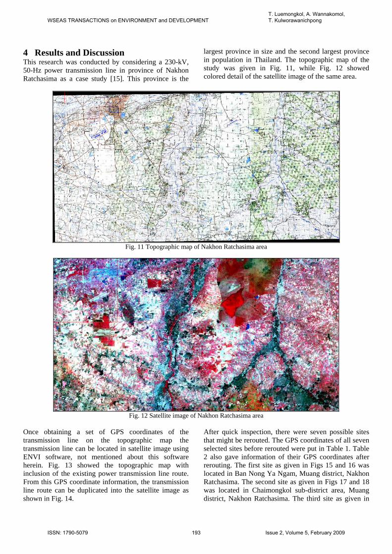
4 Results and Discussion This research was conducted by considering a 230-kV, 50-Hz power transmission line in province of Nakhon Ratchasima as a case study [15]. This province is the
largest province in size and the second largest province in population in Thailand. The topographic map of the study was given in Fig. 11, while Fig. 12 showed colored detail of the satellite image of the same area.
Fig. 11 Topographic map of Nakhon Ratchasima area
Fig. 12 Satellite image of Nakhon Ratchasima area
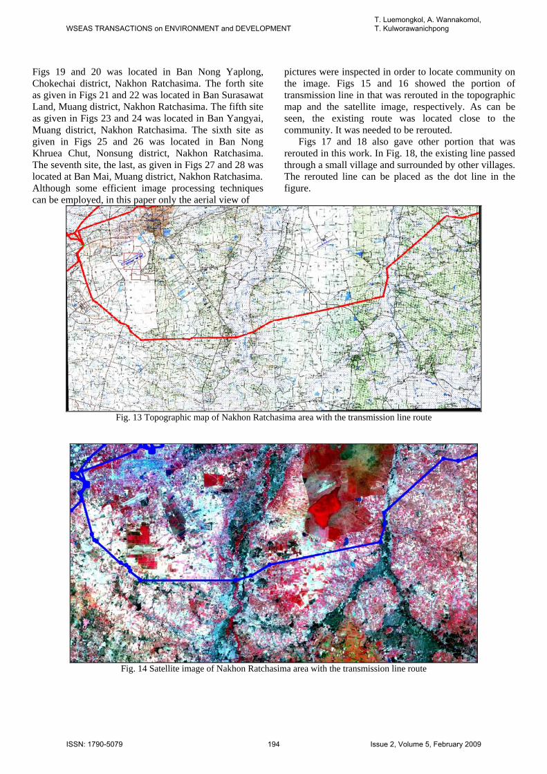
Once obtaining a set of GPS coordinates of the transmission line on the topographic map the transmission line can be located in satellite image using ENVI software, not mentioned about this software herein. Fig. 13 showed the topographic map with inclusion of the existing power transmission line route. From this GPS coordinate information, the transmission line route can be duplicated into the satellite image as shown in Fig. 14.
After quick inspection, there were seven possible sites that might be rerouted. The GPS coordinates of all seven selected sites before rerouted were put in Table 1. Table 2 also gave information of their GPS coordinates after rerouting. The first site as given in Figs 15 and 16 was located in Ban Nong Ya Ngam, Muang district, Nakhon Ratchasima. The second site as given in Figs 17 and 18 was located in Chaimongkol sub-district area, Muang district, Nakhon Ratchasima. The third site as given in
WSEAS TRANSACTIONS on ENVIRONMENT and DEVELOPMENTT. Luemongkol, A. Wannakomol, T. Kulworawanichpong
ISSN: 1790-5079 193 Issue 2, Volume 5, February 2009
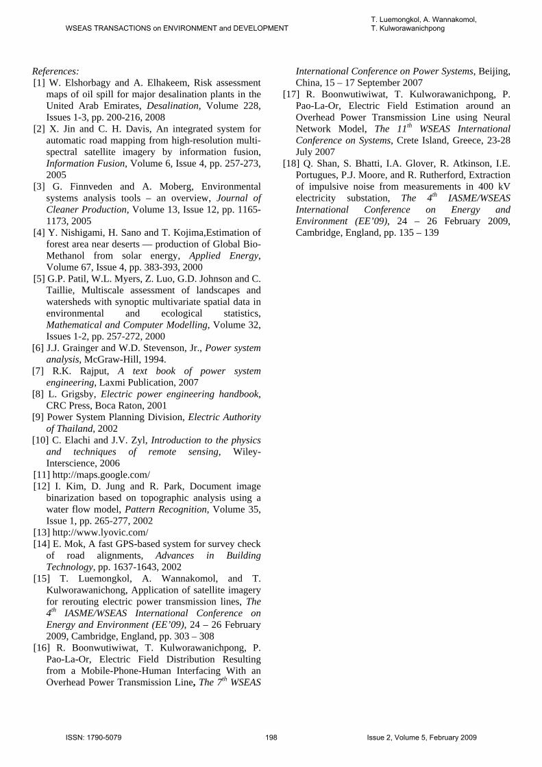
Figs 19 and 20 was located in Ban Nong Yaplong, Chokechai district, Nakhon Ratchasima. The forth site as given in Figs 21 and 22 was located in Ban Surasawat Land, Muang district, Nakhon Ratchasima. The fifth site as given in Figs 23 and 24 was located in Ban Yangyai, Muang district, Nakhon Ratchasima. The sixth site as given in Figs 25 and 26 was located in Ban Nong Khruea Chut, Nonsung district, Nakhon Ratchasima. The seventh site, the last, as given in Figs 27 and 28 was located at Ban Mai, Muang district, Nakhon Ratchasima. Although some efficient image processing techniques can be employed, in this paper only the aerial view of
pictures were inspected in order to locate community on the image. Figs 15 and 16 showed the portion of transmission line in that was rerouted in the topographic map and the satellite image, respectively. As can be seen, the existing route was located close to the community. It was needed to be rerouted.
Figs 17 and 18 also gave other portion that was rerouted in this work. In Fig. 18, the existing line passed through a small village and surrounded by other villages. The rerouted line can be placed as the dot line in the figure.
Fig. 13 Topographic map of Nakhon Ratchasima area with the transmission line route
Fig. 14 Satellite image of Nakhon Ratchasima area with the transmission line route
WSEAS TRANSACTIONS on ENVIRONMENT and DEVELOPMENTT. Luemongkol, A. Wannakomol, T. Kulworawanichpong
ISSN: 1790-5079 194 Issue 2, Volume 5, February 2009
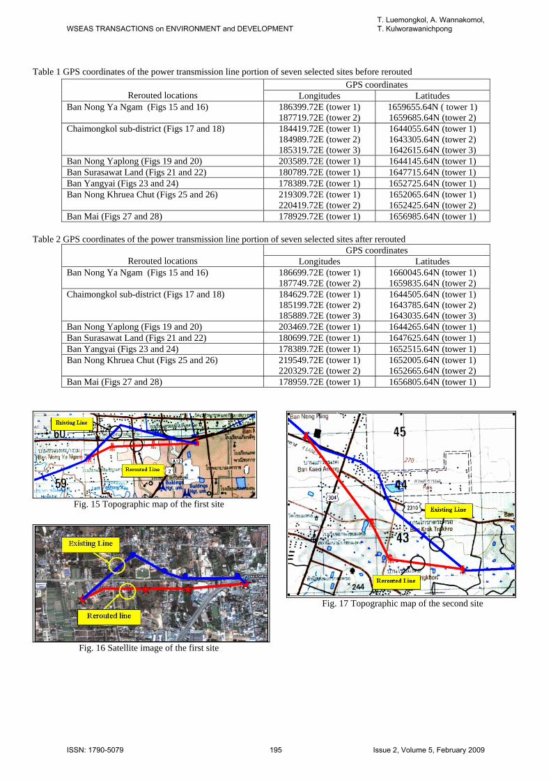
Table 1 GPS coordinates of the power transmission line portion of seven selected sites before rerouted
Table 2 GPS coordinates of the power transmission line portion of seven selected sites after rerouted
Rerouted locations
GPS coordinates Longitudes Latitudes
Ban Nong Ya Ngam (Figs 15 and 16)
186699.72E (tower 1) 187749.72E (tower 2)
1660045.64N (tower 1) 1659835.64N (tower 2)
Chaimongkol sub-district (Figs 17 and 18) 184629.72E (tower 1) 185199.72E (tower 2) 185889.72E (tower 3)
1644505.64N (tower 1) 1643785.64N (tower 2) 1643035.64N (tower 3)
Ban Nong Yaplong (Figs 19 and 20) 203469.72E (tower 1) 1644265.64N (tower 1) Ban Surasawat Land (Figs 21 and 22) 180699.72E (tower 1) 1647625.64N (tower 1) Ban Yangyai (Figs 23 and 24) 178389.72E (tower 1) 1652515.64N (tower 1) Ban Nong Khruea Chut (Figs 25 and 26) 219549.72E (tower 1)
220329.72E (tower 2) 1652005.64N (tower 1) 1652665.64N (tower 2)
Ban Mai (Figs 27 and 28) 178959.72E (tower 1) 1656805.64N (tower 1)
Fig. 15 Topographic map of the first site
Fig. 16 Satellite image of the first site
Fig. 17 Topographic map of the second site
Rerouted locations
GPS coordinates Longitudes Latitudes
Ban Nong Ya Ngam (Figs 15 and 16)
186399.72E (tower 1) 187719.72E (tower 2)
1659655.64N ( tower 1) 1659685.64N (tower 2)
Chaimongkol sub-district (Figs 17 and 18) 184419.72E (tower 1) 184989.72E (tower 2) 185319.72E (tower 3)
1644055.64N (tower 1) 1643305.64N (tower 2) 1642615.64N (tower 3)
Ban Nong Yaplong (Figs 19 and 20) 203589.72E (tower 1) 1644145.64N (tower 1) Ban Surasawat Land (Figs 21 and 22) 180789.72E (tower 1) 1647715.64N (tower 1) Ban Yangyai (Figs 23 and 24) 178389.72E (tower 1) 1652725.64N (tower 1) Ban Nong Khruea Chut (Figs 25 and 26) 219309.72E (tower 1)
220419.72E (tower 2) 1652065.64N (tower 1) 1652425.64N (tower 2)
Ban Mai (Figs 27 and 28) 178929.72E (tower 1) 1656985.64N (tower 1)
WSEAS TRANSACTIONS on ENVIRONMENT and DEVELOPMENTT. Luemongkol, A. Wannakomol, T. Kulworawanichpong
ISSN: 1790-5079 195 Issue 2, Volume 5, February 2009
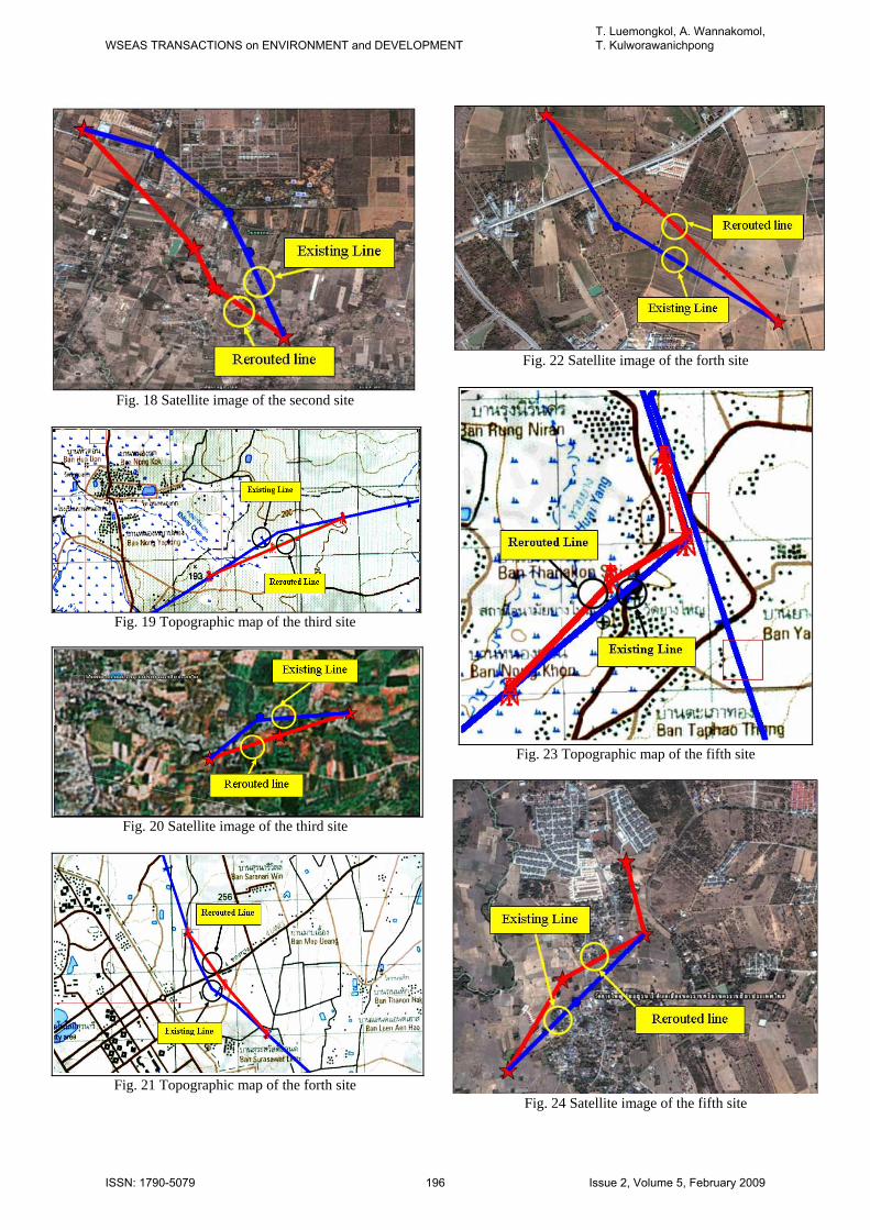
Fig. 18 Satellite image of the second site
Fig. 19 Topographic map of the third site
Fig. 20 Satellite image of the third site
Fig. 21 Topographic map of the forth site
Fig. 22 Satellite image of the forth site
Fig. 23 Topographic map of the fifth site
Fig. 24 Satellite image of the fifth site
WSEAS TRANSACTIONS on ENVIRONMENT and DEVELOPMENTT. Luemongkol, A. Wannakomol, T. Kulworawanichpong
ISSN: 1790-5079 196 Issue 2, Volume 5, February 2009
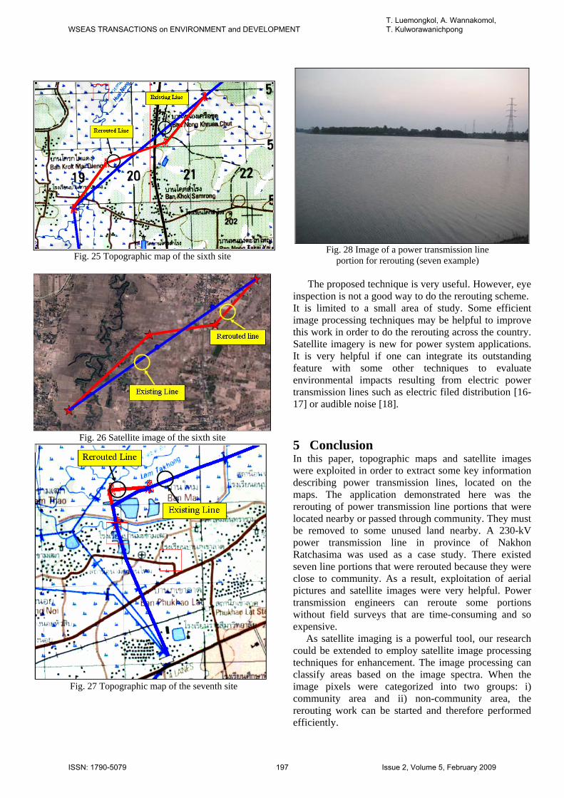
Fig. 25 Topographic map of the sixth site
Fig. 26 Satellite image of the sixth site
Fig. 27 Topographic map of the seventh site
Fig. 28 Image of a power transmission line portion for rerouting (seven example)
The proposed technique is very useful. However, eye
inspection is not a good way to do the rerouting scheme. It is limited to a small area of study. Some efficient image processing techniques may be helpful to improve this work in order to do the rerouting across the country. Satellite imagery is new for power system applications. It is very helpful if one can integrate its outstanding feature with some other techniques to evaluate environmental impacts resulting from electric power transmission lines such as electric filed distribution [16-17] or audible noise [18].
5 Conclusion In this paper, topographic maps and satellite images were exploited in order to extract some key information describing power transmission lines, located on the maps. The application demonstrated here was the rerouting of power transmission line portions that were located nearby or passed through community. They must be removed to some unused land nearby. A 230-kV power transmission line in province of Nakhon Ratchasima was used as a case study. There existed seven line portions that were rerouted because they were close to community. As a result, exploitation of aerial pictures and satellite images were very helpful. Power transmission engineers can reroute some portions without field surveys that are time-consuming and so expensive. As satellite imaging is a powerful tool, our research could be extended to employ satellite image processing techniques for enhancement. The image processing can classify areas based on the image spectra. When the image pixels were categorized into two groups: i) community area and ii) non-community area, the rerouting work can be started and therefore performed efficiently.
WSEAS TRANSACTIONS on ENVIRONMENT and DEVELOPMENTT. Luemongkol, A. Wannakomol, T. Kulworawanichpong
ISSN: 1790-5079 197 Issue 2, Volume 5, February 2009
References: [1] W. Elshorbagy and A. Elhakeem, Risk assessment
maps of oil spill for major desalination plants in the United Arab Emirates, Desalination, Volume 228, Issues 1-3, pp. 200-216, 2008
[2] X. Jin and C. H. Davis, An integrated system for automatic road mapping from high-resolution multi-spectral satellite imagery by information fusion, Information Fusion, Volume 6, Issue 4, pp. 257-273, 2005
[3] G. Finnveden and A. Moberg, Environmental systems analysis tools – an overview, Journal of Cleaner Production, Volume 13, Issue 12, pp. 1165-1173, 2005
[4] Y. Nishigami, H. Sano and T. Kojima,Estimation of forest area near deserts — production of Global Bio-Methanol from solar energy, Applied Energy, Volume 67, Issue 4, pp. 383-393, 2000
[5] G.P. Patil, W.L. Myers, Z. Luo, G.D. Johnson and C. Taillie, Multiscale assessment of landscapes and watersheds with synoptic multivariate spatial data in environmental and ecological statistics, Mathematical and Computer Modelling, Volume 32, Issues 1-2, pp. 257-272, 2000
[6] J.J. Grainger and W.D. Stevenson, Jr., Power system analysis, McGraw-Hill, 1994.
[7] R.K. Rajput, A text book of power system engineering, Laxmi Publication, 2007
[8] L. Grigsby, Electric power engineering handbook, CRC Press, Boca Raton, 2001
[9] Power System Planning Division, Electric Authority of Thailand, 2002
[10] C. Elachi and J.V. Zyl, Introduction to the physics and techniques of remote sensing, Wiley-Interscience, 2006
[11] http://maps.google.com/ [12] I. Kim, D. Jung and R. Park, Document image
binarization based on topographic analysis using a water flow model, Pattern Recognition, Volume 35, Issue 1, pp. 265-277, 2002
[13] http://www.lyovic.com/ [14] E. Mok, A fast GPS-based system for survey check
of road alignments, Advances in Building Technology, pp. 1637-1643, 2002
[15] T. Luemongkol, A. Wannakomol, and T. Kulworawanichong, Application of satellite imagery for rerouting electric power transmission lines, The 4th IASME/WSEAS International Conference on Energy and Environment (EE’09), 24 – 26 February 2009, Cambridge, England, pp. 303 – 308
[16] R. Boonwutiwiwat, T. Kulworawanichpong, P. Pao-La-Or, Electric Field Distribution Resulting from a Mobile-Phone-Human Interfacing With an Overhead Power Transmission Line, The 7th WSEAS
International Conference on Power Systems, Beijing, China, 15 – 17 September 2007
[17] R. Boonwutiwiwat, T. Kulworawanichpong, P. Pao-La-Or, Electric Field Estimation around an Overhead Power Transmission Line using Neural Network Model, The 11th WSEAS International Conference on Systems, Crete Island, Greece, 23-28 July 2007
[18] Q. Shan, S. Bhatti, I.A. Glover, R. Atkinson, I.E. Portugues, P.J. Moore, and R. Rutherford, Extraction of impulsive noise from measurements in 400 kV electricity substation, The 4th IASME/WSEAS International Conference on Energy and Environment (EE’09), 24 – 26 February 2009, Cambridge, England, pp. 135 – 139
WSEAS TRANSACTIONS on ENVIRONMENT and DEVELOPMENTT. Luemongkol, A. Wannakomol, T. Kulworawanichpong
ISSN: 1790-5079 198 Issue 2, Volume 5, February 2009


![Efficient Energy Routing with connections Rerouting in ...1989/06/02 · optical spectrum management on the problem of routing and wavelength assignment [1-3], rerouting / optical](https://img.pdfslide.us/doc/110x75/60bbe452126f001e7f6854c2/efficient-energy-routing-with-connections-rerouting-in-19890602-optical.jpg)