Embed Size (px)
Citation preview
2003-05-05 IEEE C802.20-03/67r1
Project IEEE 802.20 Working Group on Mobile Broadband Wireless Access
http://grouper.ieee.org/groups/802/20
Title Requirements: Selected topics, including MAC+PHY aggregate capacity
Date Submitted
2003-07-17
Source(s) Marianna GoldhammerTel Aviv, HaBarzel 21
Israel
Voice: +972 3 645 6241Fax: Email: [email protected]
Re: MBWA Call for Contributions 802.20-03/09
Abstract
Purpose The scope of this contribution is to improve the 802.20 Requirement document, Ver. 3.
NoticeThis document has been prepared to assist the IEEE 802.20 Working Group. It is offered as a basis for discussion and is not binding on the contributing individual(s) or organization(s). The material in this document is subject to change in form and content after further study. The contributor(s) reserve(s) the right to add, amend or withdraw material contained herein.
ReleaseThe contributor grants a free, irrevocable license to the IEEE to incorporate material contained in this contribution, and any modifications thereof, in the creation of an IEEE Standards publication; to copyright in the IEEE’s name any IEEE Standards publication even though it may include portions of this contribution; and at the IEEE’s sole discretion to permit others to reproduce in whole or in part the resulting IEEE Standards publication. The contributor also acknowledges and accepts that this contribution may be made public by IEEE 802.20.
Patent Policy
The contributor is familiar with IEEE patent policy, as outlined in Section 6.3 of the IEEE-SA Standards Board Operations Manual <http://standards.ieee.org/guides/opman/sect6.html#6.3> and in Understanding Patent Issues During IEEE Standards Development <http://standards.ieee.org/board/pat/guide.html>.
1 / 31
12
1
2
3
4
5
6
7
8
9
3
2003-05-05 IEEE C802.20-03/67 r1
Requirements: Selected topics, including MAC+PHY aggregate capacity
Marianna Goldhammer, Alvarion
1 Introduction
The scope of this contribution is to improve the 802.20 Requirement document, Ver. 3.
1. The requirements are classified in 3 categories, according to SHALL-MUST, SHOULD and MAY, to differentiate between essential and other requirements.
2. It is proposed an 802.20 Reference Model, access specific instead of WLAN specific.
3. The Version 3 of the document provides a fairly good system description, but not emphasizes enough PHY and MAC protocol requirements. As consequence, there is some confusion area between product requirements, system requirements and PHY-MAC requirements. This contribution proposes numerical performance targets (as resulting from 802.16d/e drafts), specific for PHY+MAC interface to upper layers. For simplicity sake, the performance targets are defined as function of payload size, rather than specific services, and are given at specific modulations and coding overheads, speeds and cell sizes.
4. Some other topics include issues as: statistical multiplexing, TDD/FDD, link-budget, channel models, etc.
5. All the proposed changes are highlighted, being included in-text.
2 / 312
121
2
3
4
5
6
7
8
910
1112
1314151617181920
2122
23
24
34
2003-05-05 IEEE C802.20-03/67 r1
IEEE P 802.20™/PD<insert PD Number>/V<insert version number>
Date: <July 10.2003>
Draft 802.20 Permanent Document
<802.20 Requirements Document >
This document is a Draft Permanent Document of IEEE Working Group 802.20. Permanent Documents (PD) are used in facilitating the work of the WG and contain information that provides guidance for the development of 802.20 standards. This document is work in progress and is subject to change.
3 / 313
12
1
2
3
4
5
6
7
8
9
10
11
12
13
141516171819202122
34
{July 10, 2003} IEEE P802.20-PD<number>/V<number>
Contents
1 Introduction ...................................................................................................................................... 2
2 Overview .......................................................................................................................................... 7
2.1 Scope ........................................................................................................................................ 7
2.2 Purpose ..................................................................................................................................... 7
2.3 PAR Summary .......................................................................................................................... 7
2.4 Conventions .............................................................................................................................. 8
3 Overview of Services and Applications .............................................................................................9
3.1 Voice Services .......................................................................................................................... 9
3.2 System Architecture ................................................................................................................ 10
3.2.1 MBWA-Specific Reference Model ..................................................................................10
3.3 IEEE 802 Compatibility .......................................................................................................... 12
3.4 Definition of Interfaces ............................................................................................................ 12
4 Functional and Performance Requirements .....................................................................................12
Sector Aggregate Data Rates – Downlink & Uplink ............................................................................12
4.2 Spectral Efficiency .................................................................................................................. 14
4.2.1 bps/Hz/sector ................................................................................................................... 14
4.2.2 Protocol efficiency ...........................................................................................................15
4.3 QOS ........................................................................................................................................ 15
4.4 Number of Simultaneous Sessions ...........................................................................................15
4.5 Packet Error Rate .................................................................................................................... 15
4.6 Link Budget ............................................................................................................................ 16
4.7 Receiver sensitivity .................................................................................................................16
4.8 Link Adaptation and Power Control ........................................................................................16
4.9 Max tolerable delay spread Performance under mobility ..........................................................16
4.10 Mobility .................................................................................................................................. 16
4.11 Security ................................................................................................................................... 16
4.12 Access Control ........................................................................................................................ 17
iv / 31iv
1
1
2
3
4
5
6
7
8
9
10
11
12
13
14
15
16
17
18
19
20
21
22
23
24
25
26
27
28
23
{July 10, 2003} IEEE P802.20-PD<number>/V<number>
4.13 Privacy Methods ...................................................................................................................... 17
4.14 User Privacy ............................................................................................................................ 17
4.15 Denial of Service Attacks ........................................................................................................ 17
4.15.1 Security Algorithm .......................................................................................................... 17
4.16 OA&M .................................................................................................................................... 17
4.17 Link Adaptation, Power Control, and Dynamic Bandwidth Allocation ....................................17
Duplexing modes and Channel Plans ................................................................................................18
4.19 Signaling Requirements ........................................................................................................... 18
4.20 Handoff Support ...................................................................................................................... 18
4.20.1 Soft Handoff .................................................................................................................... 18
4.20.2 Hard Handoff ................................................................................................................... 18
4.20.3 IP-Level Handoff .............................................................................................................18
4.20.4 Duplexing – FDD & TDD ................................................................................................19
4.20.5 Channel Characteristics ...................................................................................................19
4.20.6 Adaptive Modulation and Coding ....................................................................................19
4.20.7 Layer 1 to Layer 2 Inter-working .....................................................................................19
4.20.8 Hooks for Support of Multi Antenna Capabilities .............................................................19
4.21 Layer 2 MAC .......................................................................................................................... 19
4.21.1 MAC Modes of Operation (needs detail or it will be eliminated) ......................................19
4.21.2 Scheduler ......................................................................................................................... 19
4.22 Quality of Service and The MAC ............................................................................................20
4.22.1 Cos/QoS Matched-Criteria (needs detail or it will be eliminated) .....................................20
4.22.2 CoS/QoS Enforcement (needs detail or it will be eliminated) ...........................................20
4.22.3 ARQ/Retransmission (needs detail or it will be eliminated) .............................................20
4.22.4 MAC Error Performance (needs detail or it will be eliminated) ........................................20
4.22.5 Latency (needs detail or it will be eliminated) ..................................................................20
4.22.6 Protocol Support (needs detail or it will be eliminated) ....................................................20
4.22.7 Addressing (needs detail or it will be eliminated) .............................................................20
v / 31v
1
1
2
3
4
5
6
7
8
9
10
11
12
13
14
15
16
17
18
19
20
21
22
23
24
25
26
27
28
23

{July 10, 2003} IEEE P802.20-PD<number>/V<number>
4.22.8 Support/Optimization for TCP/IP (needs detail or it will be eliminated) ...........................20
4.22.9 MAC Complexity Measures .............................................................................................20
4.22.10 Additional IP Offerings(needs detail or it will be eliminated) .......................................21
4.23 Layer 3+ Support ..................................................................................................................... 21
4.23.1 OA&M Support (needs detail or it will be eliminated) .....................................................21
4.24 User State Transitions ..............................................................................................................21
4.25 Resource Allocation ................................................................................................................ 21
4.26 Latency ................................................................................................................................... 21
5 References ...................................................................................................................................... 21
Appendix A Definition of Terms and Concepts ...............................................................................23
Appendix B Unresolved issues ...................................................................................26
1 Overview .........................................................................................................5
1.1 Scope ........................................................................................................................................ 5
1.2 Purpose ..................................................................................................................................... 5
1.3 PAR Summary .......................................................................................................................... 5
2 Overview of Services and Applications .............................................................................................6
2.1 Voice Services .......................................................................................................................... 7
3 System Reference Architecture ......................................................................................................... 7
3.1 System Architecture .................................................................................................................. 7
3.1.1 MBWA-Specific Reference Model ....................................................................................8
3.2 Definition of Interfaces ............................................................................................................. 9
4 Functional and Performance Requirements .......................................................................................9
4.1 System Aggregate Data Rates – Downlink & Uplink .................................................................9
4.2 Spectral Efficiency (bps/Hz/sector) .........................................................................................10
4.3 QOS ........................................................................................................................................ 11
4.4 Number of Simultaneous Sessions ...........................................................................................11
4.5 Packet Error Rate .................................................................................................................... 11
4.6 Link Budget ............................................................................................................................ 11
vi / 31vi
1
1
2
3
4
5
6
7
8
9
10
11
12
13
14
15
16
17
18
19
20
21
22
23
24
25
26
27
28
23
{July 10, 2003} IEEE P802.20-PD<number>/V<number>
4.7 Receiver sensitivity .................................................................................................................12
4.8 Link Adaptation and Power Control ........................................................................................12
4.9 Max tolerable delay spread Performance under mobility ..........................................................12
4.10 Mobility .................................................................................................................................. 12
4.11 Security ................................................................................................................................... 12
4.12 Access Control ........................................................................................................................ 12
4.13 Privacy Methods ...................................................................................................................... 13
4.14 User Privacy ............................................................................................................................ 13
4.15 Denial of Service Attacks ........................................................................................................ 13
4.15.1 Security Algorithm .......................................................................................................... 13
4.16 OA&M .................................................................................................................................... 13
4.17 Link Adaptation, Power Control, and Dynamic Bandwidth Allocation ....................................13
4.18 Spectral Requirements ............................................................................................................. 13
4.19 Signaling Requirements ........................................................................................................... 14
4.20 Handoff Support ...................................................................................................................... 14
4.20.1 Soft Handoff .................................................................................................................... 14
4.20.2 Hard Handoff ................................................................................................................... 14
4.20.3 IP-Level Handoff .............................................................................................................14
4.20.4 Duplexing – FDD & TDD ................................................................................................14
4.20.5 Channel Characteristics ...................................................................................................14
4.20.6 Adaptive Modulation and Coding ....................................................................................14
4.20.7 Layer 1 to Layer 2 Inter-working .....................................................................................14
4.20.8 Hooks for Support of Multi Antenna Capabilities .............................................................14
4.21 Layer 2 MAC .......................................................................................................................... 15
4.21.1 MAC Modes of Operation (needs detail or it will be eliminated) ......................................15
4.21.2 Scheduler ......................................................................................................................... 15
4.22 Quality of Service and The MAC ............................................................................................16
4.22.1 Cos/QoS Matched-Criteria (needs detail or it will be eliminated) .....................................16
vii / 31vii
1
1
2
3
4
5
6
7
8
9
10
11
12
13
14
15
16
17
18
19
20
21
22
23
24
25
26
27
28
23
{July 10, 2003} IEEE P802.20-PD<number>/V<number>
4.22.2 CoS/QoS Enforcement (needs detail or it will be eliminated) ...........................................16
4.22.3 ARQ/Retransmission (needs detail or it will be eliminated) .............................................16
4.22.4 MAC Error Performance (needs detail or it will be eliminated) ........................................16
4.22.5 Latency (needs detail or it will be eliminated) ..................................................................16
4.22.6 Protocol Support (needs detail or it will be eliminated) ....................................................16
4.22.7 Addressing (needs detail or it will be eliminated) .............................................................16
4.22.8 Support/Optimization for TCP/IP (needs detail or it will be eliminated) ...........................16
4.22.9 MAC Complexity Measures .............................................................................................16
4.22.10 Additional IP Offerings(needs detail or it will be eliminated) .......................................17
4.23 Layer 3+ Support ..................................................................................................................... 17
4.23.1 OA&M Support (needs detail or it will be eliminated) .....................................................17
4.24 User State Transitions ..............................................................................................................17
4.25 Resource Allocation ................................................................................................................ 17
4.26 Latency ................................................................................................................................... 17
5 References ...................................................................................................................................... 17
Appendix A Definition of Terms and Concepts ...............................................................................19
Appendix B Unresolved issues ........................................................................................................22
viii / 31viii
1
1
2
3
4
5
6
7
8
9
10
11
12
13
14
15
16
17
18
23
{July 10, 2003} IEEE P802.20-PD<number>/V<number>
2 Overview
2.1 Scope
For the purpose of this document, an “802.20 system” constitutes an 802.20 MAC and PHY implementation in which at least one subscriber station communicates with a base station via a radio air interface, and the interfaces to external networks, for the purpose of transporting IP services through the MAC and PHY protocol layers. This document defines system requirement for the IEEE 802.20 standard development project. These requirements are consistent with the PAR document (see section 1.3 below) and shall constitute the top-level specification for the 802.20 standard.
2.2 Purpose
This document will establish the detailed requirements for the Mobile Broadband Wireless Access (MBWA) systems for which the 802.20 PHY and MAC layers shall form the lower protocol layers.
2.3 PAR Summary
The scope of the PAR (listed in Item 12) is as follows:
“Specification of physical and medium access control layers of an air interface for interoperable mobile broadband wireless access systems, operating in licensed bands below 3.5 GHz, optimized for IP-data transport, with peak data rates per user in excess of 1 Mbps. It supports various vehicular mobility classes up to 250 Km/h in a MAN environment and targets spectral efficiencies, sustained user data rates and numbers of active users that are all significantly higher than achieved by existing mobile systems.”
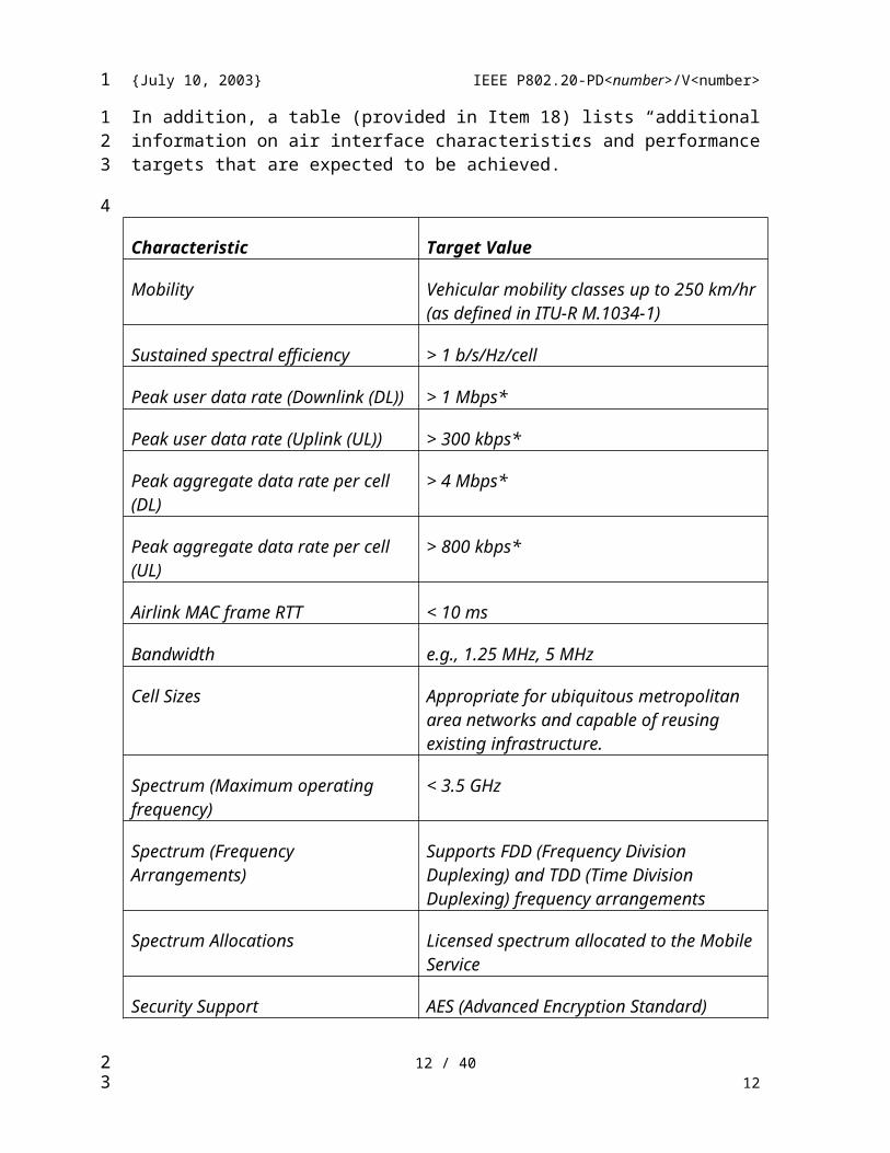
In addition, a table (provided in Item 18) lists “additional information on air interface characteristics and performance targets that are expected to be achieved.”
Characteristic Target Value
Mobility Vehicular mobility classes up to 250 km/hr (as defined in ITU-R M.1034-1)
Sustained spectral efficiency > 1 b/s/Hz/cell
9 / 319
1
1
2
3456789
10
111213
14
15
16
17181920212223
24
2526
27
23

{July 10, 2003} IEEE P802.20-PD<number>/V<number>
Peak user data rate (Downlink (DL)) > 1 Mbps*
Peak user data rate (Uplink (UL)) > 300 kbps*
Peak aggregate data rate per cell (DL) > 4 Mbps*
Peak aggregate data rate per cell (UL) > 800 kbps*
Airlink MAC frame RTT < 10 ms
Bandwidth e.g., 1.25 MHz, 5 MHz
Cell Sizes Appropriate for ubiquitous metropolitan area networks and capable of reusing existing infrastructure.
Spectrum (Maximum operating frequency)
< 3.5 GHz
Spectrum (Frequency Arrangements) Supports FDD (Frequency Division Duplexing) and TDD (Time Division Duplexing) frequency arrangements
Spectrum Allocations Licensed spectrum allocated to the Mobile Service
Security Support AES (Advanced Encryption Standard)
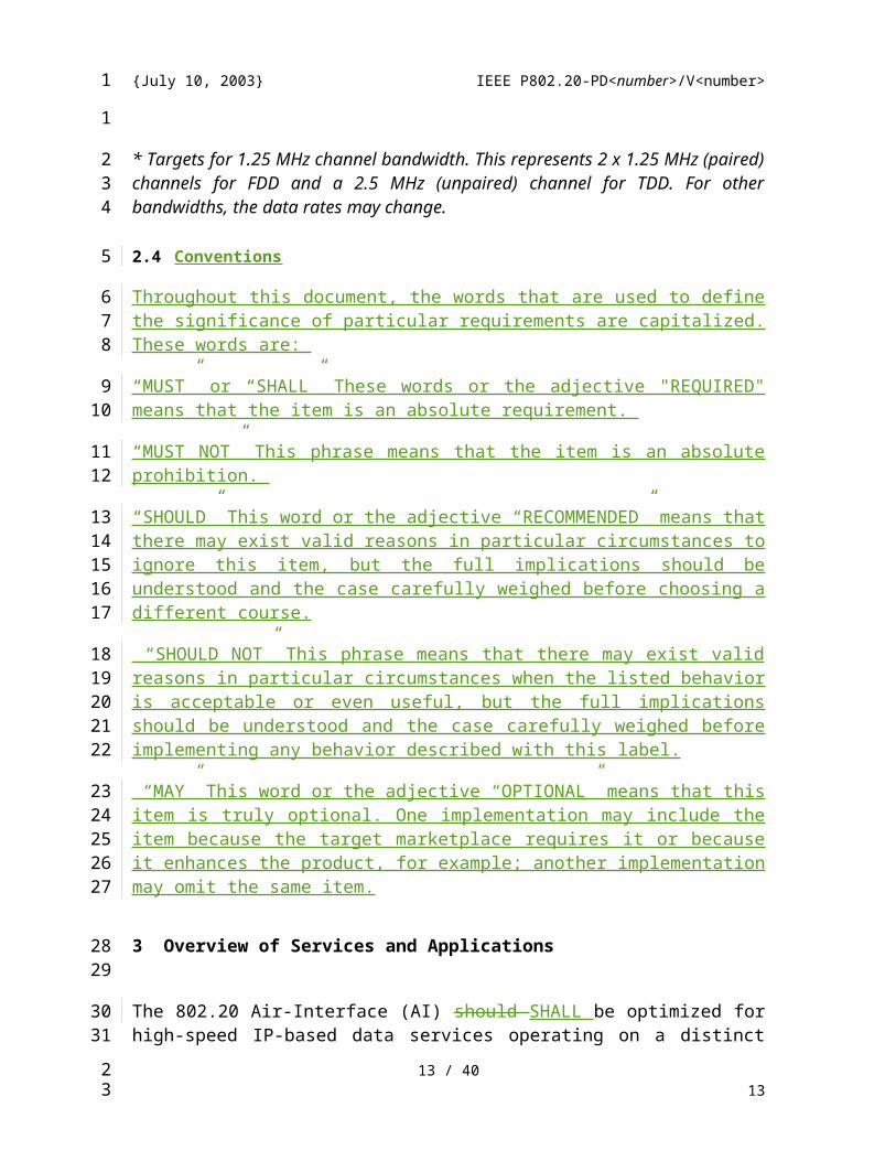
* Targets for 1.25 MHz channel bandwidth. This represents 2 x 1.25 MHz (paired) channels for FDD and a 2.5 MHz (unpaired) channel for TDD. For other bandwidths, the data rates may change.
2.4 Conventions
Throughout this document, the words that are used to define the significance of particular requirements are capitalized. These words are:
“MUST” or “SHALL” These words or the adjective "REQUIRED" means that the item is an absolute requirement.
“MUST NOT” This phrase means that the item is an absolute prohibition.
“SHOULD” This word or the adjective “RECOMMENDED” means that there may exist valid reasons in particular circumstances to ignore this item, but the full implications should be understood and the case carefully weighed before choosing a different course.
10 / 3110
1
1
234
5
67
89
10
111213
23
{July 10, 2003} IEEE P802.20-PD<number>/V<number>
“SHOULD NOT” This phrase means that there may exist valid reasons in particular circumstances when the listed behavior is acceptable or even useful, but the full implications should be understood and the case carefully weighed before implementing any behavior described with this label.
“MAY” This word or the adjective “OPTIONAL” means that this item is truly optional. One implementation may include the item because the target marketplace requires it or because it enhances the product, for example; another implementation may omit the same item.
3 Overview of Services and Applications
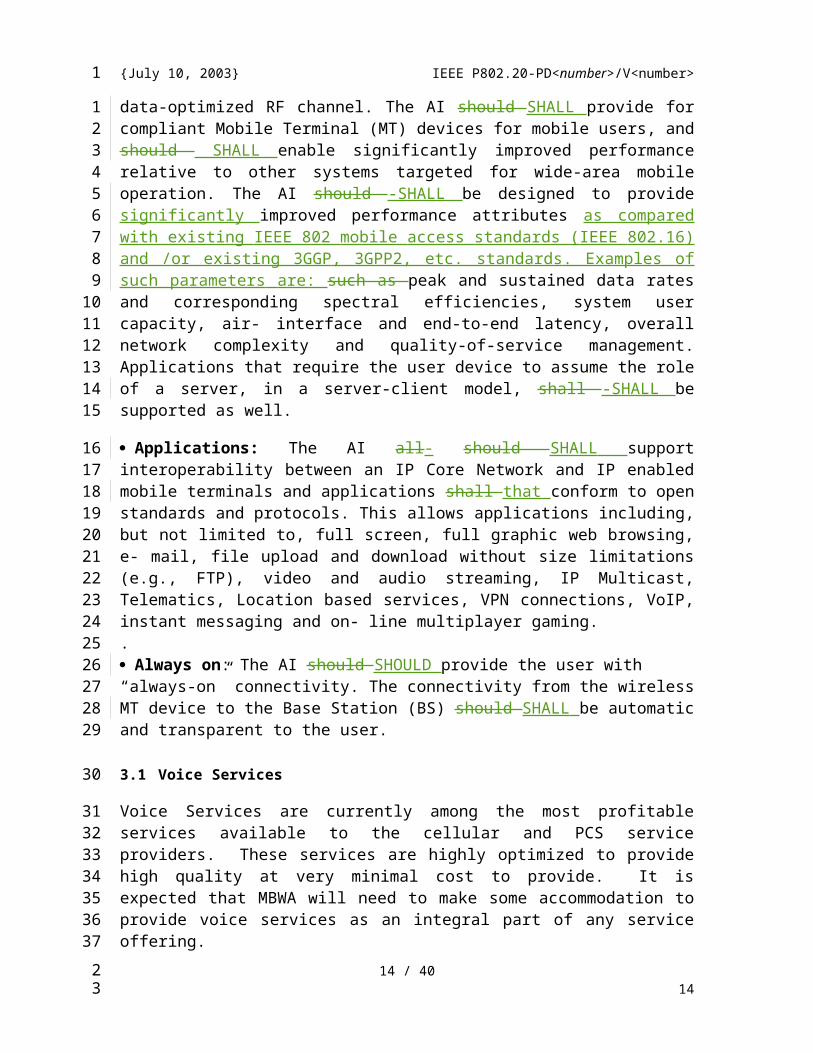
The 802.20 Air-Interface (AI) should SHALL be optimized for high-speed IP-based data services operating on a distinct data-optimized RF channel. The AI should SHALL provide for compliant Mobile Terminal (MT) devices for mobile users, and should SHALL enable significantly improved performance relative to other systems targeted for wide-area mobile operation. The AI should -SHALL be designed to provide significantly improved performance attributes as compared with existing IEEE 802 mobile access standards (IEEE 802.16) and /or existing 3GGP, 3GPP2, etc. standards. Examples of such parameters are: such as peak and sustained data rates and corresponding spectral efficiencies, system user capacity, air- interface and end-to-end latency, overall network complexity and quality-of-service management. Applications that require the user device to assume the role of a server, in a server-client model, shall -SHALL be supported as well.
Applications: The AI all- should SHALL support interoperability between an IP Core Network and IP enabled mobile terminals and applications shall that conform to open standards and protocols. This allows applications including, but not limited to, full screen, full graphic web browsing, e- mail, file upload and download without size limitations (e.g., FTP), video and audio streaming, IP Multicast, Telematics, Location based services, VPN connections, VoIP, instant messaging and on- line multiplayer gaming. .Always on: The AI should SHOULD provide the user with “always-on” connectivity. The connectivity from the wireless MT device to the Base Station (BS) should SHALL be automatic and transparent to the user.
3.1 Voice Services
Voice Services are currently among the most profitable services available to the cellular and PCS service providers. These services are highly optimized to provide high quality at very minimal cost to provide. It is expected that MBWA will need to make some accommodation to provide voice services as an integral part of any service offering.
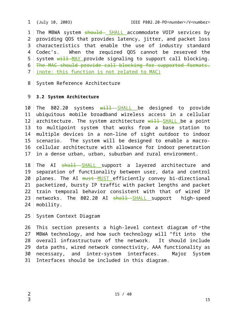
The MBWA system should SHALL accommodate VOIP services by providing QOS that provides latency, jitter, and packet loss characteristics that enable the use of industry
11 / 3111
1
1234
5678
910
111213141516171819202122
2324252627282930313233
34
35363738
3940
23
{July 10, 2003} IEEE P802.20-PD<number>/V<number>
standard Codec’s. When the required QOS cannot be reserved the system will MAY provide signaling to support call blocking. The MAC should provide call blocking for supported formats. (note: this function is not related to MAC)
System Reference Architecture
3.2 System Architecture
The 802.20 systems will SHALL be designed to provide ubiquitous mobile broadband wireless access in a cellular architecture. The system architecture will SHALL be a point to multipoint system that works from a base station to multiple devices in a non-line of sight outdoor to indoor scenario. The system will be designed to enable a macro-cellular architecture with allowance for indoor penetration in a dense urban, urban, suburban and rural environment.
The AI shall SHALL support a layered architecture and separation of functionality between user, data and control planes. The AI must MUST efficiently convey bi-directional packetized, bursty IP traffic with packet lengths and packet train temporal behavior consistent with that of wired IP networks. The 802.20 AI shall SHALL support high-speed mobility.
System Context Diagram
This section presents a high-level context diagram of the MBWA technology, and how such technology will “fit into” the overall infrastructure of the network. It should include data paths, wired network connectivity, AAA functionality as necessary, and inter-system interfaces. Major System Interfaces should be included in this diagram.
3.2.1 MBWA-Specific Reference Model
To aid the discussion in this document and in the 802.20 specifications, a straw man Reference Partitioning of the 802.20 functionality is shown in Figure 1. This reference partitioning model is similar to those used in other 802 groups.
The 802.20 reference model consists of two major functional layers, the Data Link Layer (DLL) and the Physical Layer (PHY).
The MAC comprises three sublayers. The Service Specific Convergence Sublayer (CS) provides any transformation or mapping of external network data, received through the CS service access point (SAP), into MAC SDUs (Service Data Unit) received by the MAC Common Part Sublayer (MAC CPS) through the MAC SAP. This includes classifying external network SDUs and associating them to the proper MAC service flow and Con-nection ID. It may also include such functions as payload header suppression. Multiple CS specifications are provided for interfacing with various protocols. The internal format of the CS payload is unique to the CS, and the MAC CPS is not required to
12 / 3112
1
123
4
5
6789
1011
1213141516
17
18192021
22
232425
26272829303132333435363738
23
{July 10, 2003} IEEE P802.20-PD<number>/V<number>
understand the format of or parse any information from the CS payload.The MAC Common Part Sublayer (CPS) provides the core MAC functionality of system access, bandwidth allocation, connection establishment, and connection maintenance. It receives data from the various CSs, through the MAC SAP, classified to particular MAC connections. QoS is applied to the transmission and scheduling of data over the physical layer.The MAC also contains a separate Security Sublayer providing authentication, secure key exchange, and encryption.Data, physical layer control, and statistics are transferred between the MAC CPS and the physical layer (PHY) via the PHY SAP.
The Data Link Layer is functionally responsible for a mobile station’s method of gaining access to the over-the-air resource. The Data Link Layer consists of the MAC Sub layer, and the MAC Management Sub layer. The MAC Sub layer is responsible for the proper formatting of data, as well as requesting access to the over-the-air resource. The MAC Management Sub layer is responsible for provisioning of MAC Layer Parameters and the extraction of MAC monitoring information, which can be of use in network management.
The Physical Layer consists of the Physical Layer Convergence Protocol, the Physical Medium Dependent, and the Physical Layer Management Sub layers. The Physical Layer Convergence Protocol Sub layer is responsible for the formatting of data received from the MAC Sub layer into data objects suitable for over the air transmission, and for the deformatting of data received by the station. The Physical Medium Dependent Sub layer is responsible for the transmission and reception of data to/from the over-the-air resource. The Physical Layer Management sub layer is responsible for provisioning of the Physical Layer parameters, and for the extraction of PHY monitoring information that can be of use in network management.
13 / 3113
1
123456789
1011
12131415161718
192021222324252627
28
29
23
{July 10, 2003} IEEE P802.20-PD<number>/V<number>
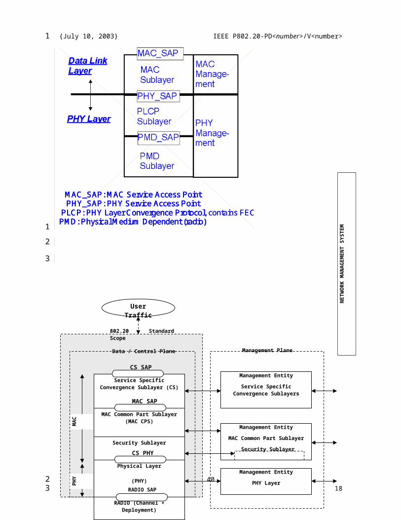
MAC_SAP: MAC Service Access PointPHY_SAP: PHY Service Access Point
PLCP: PHY Layer Convergence ProtocolPMD: Physical Medium Dependent (radio)
MAC_SAP: MAC Service Access PointPHY_SAP: PHY Service Access Point
PLCP: PHY Layer Convergence Protocol, contains FECPMD: Physical Medium Dependent (radio)
MAC_SAP: MAC Service Access PointPHY_SAP: PHY Service Access Point
PLCP: PHY Layer Convergence ProtocolPMD: Physical Medium Dependent (radio)
MAC_SAP: MAC Service Access PointPHY_SAP: PHY Service Access Point
PLCP: PHY Layer Convergence Protocol, contains FECPMD: Physical Medium Dependent (radio)
14 / 3114
Service Specific Convergence Sublayer (CS)
CS SAP
MAC Common Part Sublayer (MAC CPS)
MAC SAP
Security Sublayer
Physical Layer
(PHY)
CS PHY
RADIO (Channel + Deployment)
Management Entity
Service Specific Convergence Sublayers
Management Entity
MAC Common Part Sublayer
Security Sublayer
Management Entity
PHY Layer
Data / Control PlaneN
ETW
OR
K M
AN
AG
EMEN
T SY
STEM
MA
CPH
Y
Management Plane
802.20 Standard Scope
RADIO SAP
User Traffic
1
1
2
3
23
{July 10, 2003} IEEE P802.20-PD<number>/V<number>
Figure 1—802.20 protocol layering, showing service access points (SAPs)
Figure 1 – Reference partitioning
3.3 IEEE 802 CompatibilityThe AI protocols SHALL be in conformance with the IEEE 802.1 Architecture, Management and Interworking documents as follows: 802 Overview and Architecture, 802.1D, 802.1Q and parts of 802.1f. If any variances in conformance emerge, they SHALL be thoroughly disclosed and reviewed with 802.
3.4 Definition of Interfaces
Open interfaces: The AI shall SHOULD support open interfaces between the base station and any upstream network entities. Any AI interfaces that may be implemented shall SHALL use IETF protocols as appropriate.
4 Functional and Performance Requirements
4.1 System Sector Aggregate Data Rates – Downlink & Uplink
Consistent with the 802.20 PAR, tables 1 and 2 define the required air interface data rates and capacity characteristics. In Table 1 and Table 2, are the 802.16 d+e preview performances. The 802.20 PHY and MAC+PHY performance SHALL be better than the performance specified in Table 1, adding an improvement of at least 30% (to over-perform 802.16). Due to the fact that this standard defines mainly PHY and MAC specifications, the requirements are defined for the PHY and PHY+ system interfaces, and not at the system level.
15 / 3115
1
1
2
3
4
56789
10
11
12
131415
16
171819202122232425262728293031323334353637
23
{July 10, 2003} IEEE P802.20-PD<number>/V<number>
Table 1 – Information Data Rates and Aggregated Capacity Requirements for 1.25 MHz channel.
Description Downlink Uplink
PHY MAC+ PHY
PHY MAC+ PHY
Outdoor Peak Data Rate1, 1518 bytes payload, min. 40 users, 64QAM rate ¾ or equivalent, at max. cell size
4.5Mbps
3 3.8Mbps
4.5Mbps 3 3.6 Mbps
Outdoor Peak Data Rate1 , 40bytes payload (VoIP, etc.), min. 40users, 64QAM rate ¾ or equivalent, at max. cell size
3.2Mbps 2.5Mbps
Outdoor Average Data Rate2, 1518 bytes payload, min. 25 users, 16QAM rate ¾ or equivalent, at max. cell size, 100km/h, ITU-R Vehicular Channel A
2.7 Mbps
1 2.4 Mbps/Sect
or
2.7Mbps 1 2 Mbps/Secto
r
Outdoor Average Data Rate2 , , 40bytes payload (VoIP, etc.), min. 25 users, 64QAM rate ¾ or equivalent, at max. cell size, 100km/h, ITU-R Vehicular Channel A
2.1Mbps 1.6 Mbps
Indoor Peak Data Rate3 3 -4Mbps/Se
ctor
3 4Mbps/Sect
or
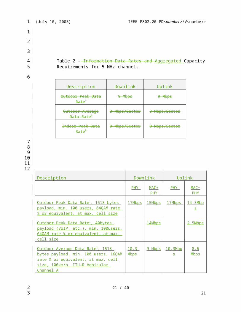
Table 2 – Information Data Rates and Aggregated Capacity Requirements for 5 MHz channel.
Description Downlink Uplink
Outdoor Peak Data Rate1 9 Mbps 9 Mbps
Outdoor Average Data Rate2 3 Mbps/Sector 3 Mbps/Sector
Indoor Peak Data Rate3 9 Mbps/Sector 9 Mbps/Sector
16 / 3116
1
123
4
5
6
7
8
910
11
121314151617
23
{July 10, 2003} IEEE P802.20-PD<number>/V<number>
Description Downlink Uplink
PHY MAC+ PHY
PHY MAC+ PHY
Outdoor Peak Data Rate1 , 1518 bytes payload, min. 100 users, 64QAM rate ¾ or equivalent, at max. cell size
17Mbps 15Mbps 17Mbps 14.3Mbps
Outdoor Peak Data Rate1 , 40bytes payload (VoIP, etc.), min. 100users, 64QAM rate ¾ or equivalent, at max. cell size
14Mbps 2.5Mbps
Outdoor Average Data Rate2 , 1518 bytes payload, min. 100 users, 16QAM rate ¾ or equivalent, at max. cell size, 100km/h, ITU-R Vehicular Channel A
10.3 Mbps
9 Mbps 10.3Mbps 8.6 Mbps
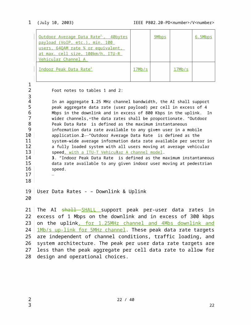
Outdoor Average Data Rate2 , , 40bytes payload (VoIP, etc.), min. 100 users, 64QAM rate ¾ or equivalent, at max. cell size, 100km/h, ITU-R Vehicular Channel A
9Mbps 6.5Mbps
Indoor Peak Data Rate3 17Mb/s 17Mb/s
Foot notes to tables 1 and 2:
In an aggregate 1.25 MHz channel bandwidth, the AI shall support peak aggregate data rate (user payload) per cell in excess of 4 Mbps in the downlink and in excess of 800 Kbps in the uplink. In wider channels, the data rates shall be proportionate. “Outdoor Peak Data Rate” is defined as the maximum instantaneous information data rate available to any given user in a mobile application.2. “Outdoor Average Data Rate” is defined as the system-wide average information data rate available per sector in a fully loaded system with all users moving at average vehicular speed, with a ITU-T Vehicular A channel model. 3. “Indoor Peak Data Rate” is defined as the maximum instantaneous data rate available to any given indoor user moving at pedestrian speed.
User Data Rates - – Downlink & Uplink
The AI shall SHALL support peak per-user data rates in excess of 1 Mbps on the downlink and in excess of 300 kbps on the uplink, for 1.25MHz channel and 4Mbs downlink and 1Mb/s up-link for 5MHz channel. These peak data rate targets are independent of channel conditions, traffic loading, and system architecture. The peak per user data rate targets are less than the peak aggregate per cell data rate to allow for design and operational choices.
17 / 3117
1
123456789
1011121314
1516
171819202122
23
{July 10, 2003} IEEE P802.20-PD<number>/V<number>
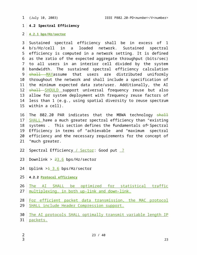
4.2 Spectral Efficiency
4.2.1 bps/Hz/sector
Sustained spectral efficiency shall be in excess of 1 b/s/Hz/cell in a loaded network. Sustained spectral efficiency is computed in a network setting. It is defined as the ratio of the expected aggregate throughput (bits/sec) to all users in an interior cell divided by the system bandwidth. The sustained spectral efficiency calculation shall MAYassume that users are distributed uniformly throughout the network and shall include a specification of the minimum expected data rate/user. Additionally, the AI shall SHOULD support universal frequency reuse but also allow for system deployment with frequency reuse factors of less than 1 (e.g., using spatial diversity to reuse spectrum within a cell).
The 802.20 PAR indicates that the MBWA technology shall SHALL have a much greater spectral efficiency than “existing systems”. This section defines the fundamentals of Spectral Efficiency in terms of “achievable” and “maximum” spectral efficiency and the necessary requirements for the concept of “much greater.”
Spectral Efficiency / Sector: Good put ?
Downlink > 23.6 bps/Hz/sector
Uplink >1 3.6 bps/Hz/sector
4.2.2 Protocol efficiency
The AI SHALL be optimized for statistical traffic multiplexing, in both up-link and down-link.
For efficient packet data transmission, the MAC protocol SHALL include Header Compression support.
The AI protocols SHALL optimally transmit variable length IP packets.
Processes as Bandwidth Request, Network Entry, etc. SHALL use minimum spectrum resources.
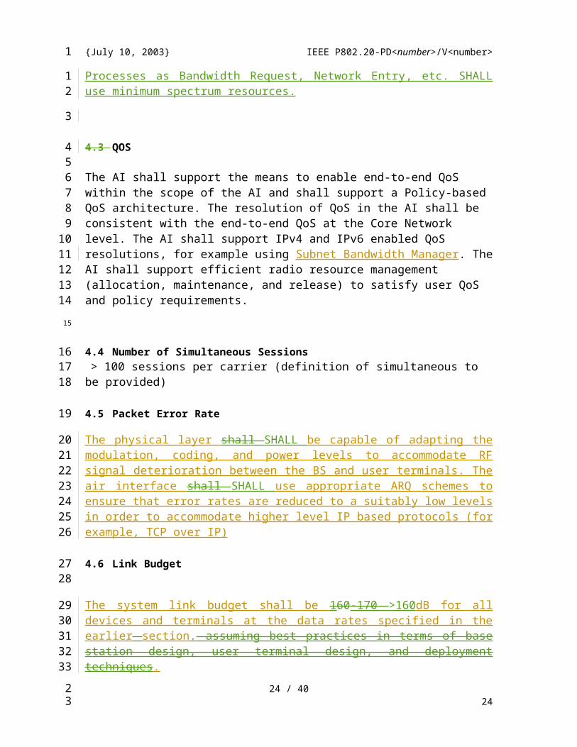
4.3 QOS
The AI shall support the means to enable end-to-end QoS within the scope of the AI and shall support a Policy-based QoS architecture. The resolution of QoS in the AI shall be consistent with the end-to-end QoS at the Core Network level. The AI shall support IPv4 and IPv6 enabled QoS resolutions, for example using Subnet Bandwidth Manager. The AI shall support efficient radio resource management (allocation, maintenance, and release) to satisfy user QoS and policy requirements.
18 / 3118
1
1
2
3456789
10
11121314
15
16
17
18
1920
2122
23
2425
26
2728293031323334
35
23

{July 10, 2003} IEEE P802.20-PD<number>/V<number>
4.4 Number of Simultaneous Sessions > 100 sessions per carrier (definition of simultaneous to be provided)
4.5 Packet Error Rate
The physical layer shall SHALL be capable of adapting the modulation, coding, and power levels to accommodate RF signal deterioration between the BS and user terminals. The air interface shall SHALL use appropriate ARQ schemes to ensure that error rates are reduced to a suitably low levels in order to accommodate higher level IP based protocols (for example, TCP over IP)
4.6 Link Budget
The system link budget shall be 160-170 >160dB for all devices and terminals at the data rates specified in the earlier section. assuming best practices in terms of base station design, user terminal design, and deployment techniques.
The PHY protocol SHALL provide maximum system gain in NON-LOS, when working with Rayleigh channels.
Taking into account that generally all the known PHYs may support Advanced Antenna Systems, the system gain MUST be evaluated primarily for the system using no more than one antenna, and secondary for systems including Antenna Arrays.
The System Gain will be evaluated taking the same assumptions for Transmitted Powers and Antenna Gains.
4.7 Receiver sensitivity
Blocking and selectivity specifications shall SHOULD be consistent with best commercial practice for mobile wide-area terminals.
4.8 Link Adaptation and Power Control
The AI shall support automatic selection of optimized user data rates that are consistent with the RF environment constraints and application requirements. The AI shall SHALL provide for graceful reduction or increasing user data rates, on the downlink and uplink, as a mechanism to maintain an appropriate frame error rate performance. The Radio system should provide at least 99.9% link reliability.
19 / 3119
1
12
3
45678
910
111213
1415
161718
1920
21
22
2324
25
2627282930
23

{July 10, 2003} IEEE P802.20-PD<number>/V<number>
4.9 Max tolerable delay spread Performance under mobility
The system is expected to work in dense urban, suburban and rural outdoor-indoor environments and the relevant channel models should be applicable. The system shall AI SHALL NOT be designed for indoor only and outdoor only scenarios.
The system SHALL have optimized performance with a variety of radio channels, taking into account the outdoor-to-indoor propagation.
Mobility
Support different modes of mobility from pedestrian (3 km/hr) to very high speed (250 km/hr) but not optimized for only one mode. As an example, data rate gracefully degrades from pedestrian to high-speed mobility.
4.10 Security
Network security in MBWA systems is assumed to have goals similar to those in cellular or PCS systems. These goals are to protect the service provider from theft of service, and to protect the user’s privacy and mitigate against denial of service attacks. Provision shall SHALL be made for authentication of both base station and mobile terminal, for privacy, and for data integrity consistent with the best current commercial practice.
4.11 Access Control
A cryptographically generated challenge-response authentication mechanism for the user to authenticate the network and for the network to authenticate the user must be used.
4.12 Privacy Methods
A method that will provide message integrity across the air interface to protect user data traffic, as well as signaling messages from unauthorized modification will be specified.
Encryption across the air interface to protect user data traffic, as well as signaling messages, from unauthorized disclosure will be incorporated.
4.13 User Privacy
The system will prevent the unauthorized disclosure of the user identity.
4.14 Denial of Service Attacks
It shall be possible to prevent replay attacks by minimizing the likelihood that authentication signatures are reused.
It shall be possible to provide protection against Denial of Service (DOS) attacks.
20 / 3120
1
1
234
56
7
89
10
11
1213141516
17
18
1920
21
2223
2425
26
27
28
2930
31
23
{July 10, 2003} IEEE P802.20-PD<number>/V<number>
4.14.1 Security Algorithm
The authentication and encryption algorithms shall be publicly available on a fair and non-discriminatory basis.
National or international standards bodies shall have approved the algorithms.
The algorithms shall have been extensively analysed by the cryptographic community to resist all currently known attacks.
4.15 OA&M
4.16 Link Adaptation, Power Control, and Dynamic Bandwidth Allocation
Link adaptation shall be used by the AI for increasing spectral efficiency, peak data rate, and cell coverage reliability. The AI shall SHALL support adaptive modulation and coding, adaptive bandwidth allocation, and adaptive power allocation.
4.17 Spectral Duplexing modes and Channel Plans Requirements
The system shall be targeted for use in TDD and FDD licensed spectrum allocated to mobile services below 3.5GHz.
The 802.20 standard SHALL support both Frequency Division Duplex (FDD) and Time Division Duplex (TDD) frequency arrangements.
The same PHY protocol SHALL support both FDD and TDD. The PHY and MAC protocols shall allow, when operating in FDD mode, the half-duplex subscriber terminal operation.
The AI shall be designed for deployment within existing and future licensed spectrum below 3.5 GHz. The MBWA system frequency plan shall SHALL include both paired and unpaired channel plans with multiple bandwidths, e.g., 1.25 or 5 MHz, etc., to allow co-deployment with existing cellular systems. Channel bandwidths are consistent with frequency plans and frequency allocations for other wide-area systems
The design shall SHOULD be readily extensible to wider channels as they become available in the future.
21 / 3121
1
1
23
4
56
7
8
91011
12
13
1415
1617
181920
2122232425
2627
23
{July 10, 2003} IEEE P802.20-PD<number>/V<number>
4.18 Signaling Requirements
4.19 Handoff Support
Handoff methods are required in MBWA systems to facilitate providing continuous service for a population of moving Mobile Stations. Mobile stations may move between cells, between systems, between frequencies, and at the higher layer between IP Subnets. At the lowest layers, handoffs can be classified as either soft or hard handoffs, depending on whether there is a momentary service disruption or not.
4.19.1 Soft Handoff
4.19.2 Hard Handoff
4.19.2.1 Hard Handoff Between Similar MBWA Systems
4.19.2.2 Hard Handoff Between Frequencies
4.19.3 IP-Level Handoff
In order to support high speed mobility in an all IP network Mobile IP will have to be supported at a higher level. Integration of Foreign Agent or proxy Mobile IP into the base station or terminal will be required to support a clientless solution. Multiple IP addresses behind a single terminal should also be supported.
4.19.4 Duplexing – FDD & TDD
The 802.20 standard shall support both Frequency Division Duplex (FDD) and Time Division Duplex (TDD) frequency arrangements. (duplicate paragraph)
RF Channelization
4.19.4.1 Bands of Applicability
4.19.4.2 Spectral Masks
4.19.5 Channel Characteristics
4.19.6 Adaptive Modulation and Coding
The system will have adaptive modulation in both the uplink and the downlink
4.19.7 Layer 1 to Layer 2 Inter-working
The interface between layers 1 and 2 is not an exposed interface; it may be handled at the implementer’s discretion.
4.19.8 Hooks for Support of Multi Antenna Capabilities
Support will be provided for advanced antenna technologies to achieve higher effective data rates, user capacity, cell sizes and reliability. Antenna diversity shall SHOULD not be a requirement of the mobile station.
22 / 3122
1
1
2
34567
8
9
10
11
12
13141516
17
1819
20
21
22
23
24
25
26
2728
29
30313233
23
{July 10, 2003} IEEE P802.20-PD<number>/V<number>
The same PHY and MAC protocols SHALL optimally support Advanced Antenna techniques, in both FDD and TDD.
4.20 Layer 2 MAC
4.20.1 MAC Modes of Operation (needs detail or it will be eliminated)
4.20.1.1 Random Access MAC (needs detail or it will be eliminated)
4.20.1.2 Polled MAC (needs detail or it will be eliminated)
4.20.2 Scheduler
The AI specification shall SHOULD not preclude proprietary scheduling algorithms, so long as the standard control messages, data formats, and system constraints are observed.
4.21 Quality of Service and The MAC
4.21.1 Cos/QoS Matched-Criteria (needs detail or it will be eliminated)
4.21.1.1 Protocol field mapping (needs detail or it will be eliminated)
4.21.1.2 Hardware mapping (needs detail or it will be eliminated)
4.21.2 CoS/QoS Enforcement (needs detail or it will be eliminated)
4.21.2.1 Inter-packet delay variation (needs detail or it will be eliminated)
4.21.2.2 One-way, round-trip delay (needs detail or it will be eliminated)
4.21.2.3 Prioritization (needs detail or it will be eliminated)
4.21.2.4 Error correction (needs detail or it will be eliminated)
4.21.2.5 Queuing (needs detail or it will be eliminated)
4.21.2.6 Suppression (needs detail or it will be eliminated)
4.21.3 ARQ/Retransmission (needs detail or it will be eliminated)
The AI SHALL efficiently support ARQ, for both up-link and down-link directions.
23 / 3123
1
123
4
5
6
7
8
91011
12
13
14
15
16
17
18
19
20
21
22
23
24
23
{July 10, 2003} IEEE P802.20-PD<number>/V<number>
4.21.4 MAC Error Performance (needs detail or it will be eliminated)
4.21.5 Latency (needs detail or it will be eliminated)
4.21.5.1 End to End Latency (needs detail or it will be eliminated)
4.21.5.2 End to End Latency Variation (needs detail or it will be eliminated)
4.21.6 Protocol Support (needs detail or it will be eliminated)
The PHY and MAC protocols SHALL support both Ipv4 and Ipv6.
4.21.7 Addressing (needs detail or it will be eliminated)
4.21.8 Support/Optimization for TCP/IP (needs detail or it will be eliminated)
4.21.9 MAC Complexity Measures
To make the MBWA technology commercially feasible, it is necessary the complexity is minimized at the MAC, consistent with the goals defined for the technologies. This section defines complexity measures to be used in estimating MAC complexity. \
4.21.10 Additional IP Offerings(needs detail or it will be eliminated)
4.22 Layer 3+ Support
4.22.1 OA&M Support (needs detail or it will be eliminated)
4.23 User State Transitions
The AI shall support multiple protocol states with fast and dynamic transitions among them. It will provide efficient signaling schemes for allocating and de-allocating resources, which may include logical in-band and/or out-of-band signaling, with respect to resources allocated for end-user data. The AI shall support paging polling schemes for idle terminals to promote power conservation for MTs.
4.24 Resource Allocation
The AI shall support fast resource assignment and release procedures on the uplink and Duplexing – FDD & TDD
4.25 Latency
The system should have a one-way target latency of 50 msecs from the base station to the end-device when the system is under load.
24 / 3124
1
1
2
3
4
5
6
7
8
9
10
11
121314
15
16
17
18
1920212223
24
2526
27
2829
23
{July 10, 2003} IEEE P802.20-PD<number>/V<number>
The AI shall minimize the round-trip times (RTT) and the variation in RTT for acknowledgements, within a given QoS traffic class, over the air interface. The RTT over the airlink for a MAC data frame is defined here to be the duration from when a data frame is received by the physical layer of the transmitter to the time when an acknowledgment for that frame is received by the transmitting station. The airlink MAC frame RTT, which can also be called the “ARQ loop delay,” shall be less than 10 ms. Fast acknowledgment of data frames allows for retransmissions to occur quickly, reducing the adverse impact of retransmissions on IP packet throughput. This particularly improves the performance of gaming, financial, and other real-time low latency transactions.
5 References
802.20 - PD-02: Mobile Broadband Wireless Access Systems: Approved PAR (02/12/11)
802.20 - PD-03: Mobile Broadband Wireless Access Systems: Five Criteria (FINAL) (02/11/13)
C802.20-03/45r1: Desired Characteristics of Mobile Broadband Wireless Access Air Interface (Arif Ansari, etc.(2003-05-12))
C802.20-03/47r1: Terminology in the 802.20 PAR (Rev 1) (Johanne Wilfson, etc. (2003-05-12))
C802.20-03/32: Selected topics – Mobile System Requirements and Evaluation Criteria (Marianna Goldhammer)
25 / 3125
1
123456789
10
11
1213
1415
1617
1819
2021222324
25
23
{July 10, 2003} IEEE P802.20-PD<number>/V<number>
Appendix A Definition of Terms and Concepts
Active users - An active user is a terminal that is registered with a cell and is using or seeking to use air link resources to receive and/or transmit data within a short time interval (e.g., within 100 ms).
Airlink MAC Frame RTT - The round-trip time (RTT) over the airlink for a MAC data frame is defined here to be the duration from when a data frame is received by the physical layer of the transmitter to the time when an acknowledgment for that frame is received by the transmitting station.
Bandwidth or Channel bandwidth - Two suggested bandwidths are 1.25 MHz and 5 MHz, which correspond to the bandwidth of one channel (downlink or uplink) for paired FDD spectrum.
Cell - The term “cell” refers to one single-sector base station or to one sector of a base station deployed with multiple sectors.
Cell sizes – The maximum distance from the base station to the mobile terminal over which an acceptable communication can maintained or before which a handoff would be triggered determines the size of a cell.
Frequency Arrangements – The frequency arrangement of the spectrum refers to its allocation for paired or unpaired spectrum bands to provide for the use of Frequency-Division Duplexing (FDD) or Time-Division Duplexing (TDD), respectively. The PAR states that the 802.20 standard should support both these frequency arrangements.
Interoperable – Systems that conform to the 802.20 specifications should interoperate with each other, e.g., regardless of manufacturer. (Note that this statement is limited to systems that operate in accordance with the same frequency plan. It does not suggest that an 802.20 TDD system would be interoperable with an 802.20 FDD system.)
Licensed bands below 3.5 GHz – This refers to bands that are allocated to the Mobile Service and licensed for use by mobile cellular wireless systems operating below 3.5 GHz.
MAN – Metropolitan Area Network.
Mobile Broadband Wireless Access systems – This may be abbreviated as MBWA and is used specifically to mean “802.20 systems” or systems compliant with an 802.20 standard.
Optimized for IP Data Transport – Such an air interface is designed specifically for carrying Internet Protocol (IP) data traffic efficiently. This optimization could
26 / 3126
1
1
234
5678
91011
1213
141516
1718192021
2223242526
272829
30
313233
3435
23
{July 10, 2003} IEEE P802.20-PD<number>/V<number>
involve (but is not limited to) increasing the throughput, reducing the system resources needed, decreasing the transmission latencies, etc.
Peak aggregate data rate per cell – The peak aggregate data rate per cell is the total data rate transmitted from (in the case of DL) or received by (in the case of UL) a base station in a cell (or in a sector, in the case of a sectorized configuration), summed over all mobile terminals that are simultaneously communicating with that base station.
Peak data rates per user (or peak user data rate) – The peak data rate per user is the highest theoretical data rate available to applications running over an 802.20 air interface and assignable to a single mobile terminal. The peak data rate per user can be determined from the combination of modulation constellation, coding rate and symbol rate that yields the maximum data rate.
Spectral efficiency – Spectral efficiency is measured in terms of bits/s/Hz/cell. (In the case of a sectorized configuration, spectral efficiency is given as bits/s/Hz/ sector.)
Sustained spectral efficiency – Sustained spectral efficiency is computed in a network setting. It is defined as the ratio of the expected aggregate throughput (bits/sec) to all users in an interior cell divided by the system bandwidth (Hz). The sustained spectral efficiency calculation should assume that users are distributed uniformly throughout the network and should include a specification of the minimum expected data rate/user.
Sustained user data rates – Sustained user data rates refer to the typical data rates that could be maintained by a user, over a period of time in a loaded system. The evaluation of the sustained user data rate is generally a complicated calculation to be determined that will involve consideration of typical channel models, environmental and geographic scenarios, data traffic models and user distributions.
Targets for 1.25 MHz channel bandwidth – This is a reference bandwidth of 2 x 1.25 MHz for paired channels for FDD systems or a single 2.5 MHz channel for TDD systems. This is established to provide a common basis for measuring the bandwidth-dependent characteristics. The targets in the table indicated by the asterisk (*) are those dependent on the channel bandwidth. Note that for larger bandwidths the targets may scale proportionally with the bandwidth.
Various vehicular mobility classes – Recommendation ITU-R M.1034-1 establishes the following mobility classes or broad categories for the relative speed between a mobile and base station:
o Stationary (0 km/h),
o Pedestrian (up to 10 km/h)
o Typical vehicular (up to 100 km/h)
o High speed vehicular (up to 500 km /h)
27 / 3127
1
12
34567
89
101112
1314
151617181920
2122232425
262728293031
323334
35
36
37
38
23
{July 10, 2003} IEEE P802.20-PD<number>/V<number>
o Aeronautical (up to 1 500 km/h)
o Satellite (up to 27 000 km/h).
28 / 3128
1
1
23
23
{July 10, 2003} IEEE P802.20-PD<number>/V<number>
Appendix B Unresolved issues
Coexistence and Interference Resistance
Since MBWA technology will be operative in licensed bands some of which are currently being utilized by other technologies, it is important that coexistence and interference issues be considered from the outset, unlike the situation in unlicensed spectrum where there is much more freedom of design. Of particular interest is adjacent channel interference; if MBWA is deployed adjacent to any of a number of technologies, the development effort should evaluate potential effects.
Interference can be grouped as co-channel and adjacent channel interference; evaluation of all combinations of technologies likely to be encountered should be part of the 802.20 processes. Furthermore, 802.20 technology is described in the PAR to encompass both TDD and FDD techniques. These should be evaluated separately, and requirements provided below.
5.1 Coexistence Scenarios
FDD Deployments
In this section, scenarios should be developed with 802.20 deployed as FDD, following the FDD “rules” for each of the 2G and 3G technologies likely to be encountered in practice.
802.20 and AMPS
802.20 and IS-95
802.20 and GSM
802.20 and LMR
802.20 and CDMA2000
802.20 and WCDMA
802.20 and 1xEVDO
802.20 and HSDPA
802.20 and 1xEV/DV
5.1.2 TDD Deployments
In this section, scenarios should be developed with 802.20 deployed as TDD, following any TDD “rules” for each of the 2G and 3G technologies likely to be encountered in practice. Since the majority of existing technologies are deployed as FDD solutions, some new ground is being explored here, and it will be necessary to make sure that the 802.20 technology will not seriously impact the existing services.
29 / 3129
1
1
2
34567
89
1011
12
13
141516
17
18
19
20
21
22
23
24
25
26
27
2829303132
23
{July 10, 2003} IEEE P802.20-PD<number>/V<number>
802.20 and AMPS
802.20 and IS-95
802.20 and GSM
802.20 and LMR
802.20 and CDMA2000
802.20 and WCDMA
802.20 and 1xEVDO
802.20 and HSDPA
802.20 and 1xEV/DV
Adjacent Channel Interference
Definitions and Characteristics
Requirements
Co-channel Interference
Definitions and Characteristics
Requirements
TDD Interference in Traditionally FDD Bands
Since 802.20 is listed as being both TDD and FDD, it should be evaluated in a scenario where TDD 802.20 technology is deployed in a traditionally FDD frequency band. 802.20 should develop appropriate scenarios and requirements so that the new technology meets all necessary coexistence requirements that may be placed upon it.
Definition and Characteristics
Requirements
Interworking: The AI should support interworking with different wireless access systems, e.g. wireless LAN, 3G, PAN, etc. Handoff from 802.20 to other technologies should be considered and where applicable procedures for that hand-off shall be supported.[Dan Gal [email protected]]: This issue is quite critical to the successful deployment of 802.20 systems in existing and future markets worldwide. The purpose of defining Coexistence requirements in this document is to assure that 802.20 systems would not cause interference to or be susceptible to interference from other wireless systems operating in the same geographical area. Detailed quantitative RF emission limits need to be specified as well as received interference levels that the 802.20 receivers would have to accept and mitigate.
30 / 3130
1
1
2
3
4
5
6
7
8
9
10
11
12
13
14
15
16
17181920
21
22
232425262728293031
23
{July 10, 2003} IEEE P802.20-PD<number>/V<number>
2. Interworking
[Dan Gal [email protected]]: Interworking between 802.20 systems and other wireless systems is highly desirable and may give it a competitive edge. Systems that have disparate physical layers can still interwork via the higher protocol layers. Current interworking solutions exist for CDMA2000/802.11b and for GSM-GPRS/802.11b. Multi-mode devices, such as 802.11b+802.11a or more recently, 802.11b/g are now available. Existing applications (such as Windows XP mobility support) provide for transparent roaming across systems, automatically handling the applications’ reconfiguration so as to keep sessions working seamlessly.
Building support for interworking in 802.20 – right from the first release of the standard – would add significantly to its market appeal.
31 / 3131
1
1
2345678
910
11
23