Embed Size (px)
Citation preview
Requirements to the
Lubrication Control of the
FlexxPump4 D424A / 404DLS
Customer: External, for information purposes only Location: GCH
Project / Order: No
Serial number: No
Function block overview Requirements to the Lubrication Control of the FlexxPump4 D424A / 404DLS
Page 2 from 25 Lubrication_Controls_Requirements_V1.8.docx
© GÜDEL
Original Manual
Reproduction of the manual, even in part, is only permitted with our
permission. Subject to change due to technical improvements..
Güdel is not liable for any damage caused by integration of the lubrication
system FlexxPump into the complete system in accordance with these
requirements. This document is for information purposes only. Any
information shall be considered to be a proposal. Full responsibility for correct
integration into the complete system lies with the customer.
Requirements to the Lubrication Control of the FlexxPump4 D424A / 404DLS Function block overview
24.10.2017 Page 3 from 25
Abstract
This document describes the requirements to the lubrication control.
Document control
Version Datum Name Beschreibung
V1.0 24.10.2017 martho Document created
V1.2 23.11.2017 martho First release
V1.3 16.01.2018 martho Timing diagrams and times
adapted, based on the right
firmware document from
TriboServ
Different optimization and
improvements of the function
description (Fill / Normal Cycle)
Included HMI sample with
minimal and maximal
implementation.
V1.4 06.02.2018 martho Explanation of indicator time as
an option. Optimization of the
indicator descriptions.
Included input value for counting
up time depending on the axis
motion
HMI sample updated
V1.5 22.02.2018 martho Included output signals from the
indicators. 3 outputs for the axis
distance and 1 output for the
current cycle counter value and 1
output for the time that passed
since the last lubrication cycle.
HMI sample updated
Flow chart replaced
Improvements made to detail
description
V1.6
06.07.2018 martho Title picture exchanged
Link for lubricant calculator
included
Function block overview Requirements to the Lubrication Control of the FlexxPump4 D424A / 404DLS
Page 4 from 25 Lubrication_Controls_Requirements_V1.8.docx
Version Datum Name Beschreibung
V1.7 07.02.2019 martho Replace picture timing diagram
Fig. 5
V1.8 11.11.2020 chrvet Replace FlexxPump 404DLS with
FlexxPump4 D424A
Tab. 1 Revision History
Requirements to the Lubrication Control of the FlexxPump4 D424A / 404DLS Function block overview
24.10.2017 Page 5 from 25
Content
1 Function block overview ................................................................ 6
1.1 Flow chart: Lubrication process......................................................................... 7
2 Interface description: Function block ........................................... 8
2.1 Inputs........................................................................................................................ 8
2.2 Outputs ................................................................................................................. 10
3 Detailed description of functions................................................. 11
3.1 Indicator handler ................................................................................................. 11
3.1.1 Axis distance ........................................................................................................ 11
3.1.2 Automatic cycle counter ................................................................................... 12
3.1.3 Timer...................................................................................................................... 13
3.1.4 Manual start .......................................................................................................... 13
3.2 Lubrication function of the FlexxPump .......................................................... 14
3.2.1 Normal lubrication cycle ................................................................................... 14
3.2.2 Fill function ........................................................................................................... 16
3.2.3 Feedback signal .................................................................................................... 18
3.2.4 Level indicator (optional function) .................................................................. 19
3.2.5 Recommended constant values ........................................................................ 20
3.3 Reaction / warning / error ................................................................................ 20
bWarnMsgCmd: ............................................................................................. 20
bWarnMsgEmtpy: ........................................................................................... 20
bWarnMsgPump: ............................................................................................ 21
bErrMsgStopReq: ........................................................................................... 21
4 Sample of an HMI screen ............................................................. 22
4.1 Minimal implementation ..................................................................................... 22
4.2 Maximal implementation .................................................................................... 23
Function block overview Requirements to the Lubrication Control of the FlexxPump4 D424A / 404DLS
Page 6 from 25 Lubrication_Controls_Requirements_V1.8.docx
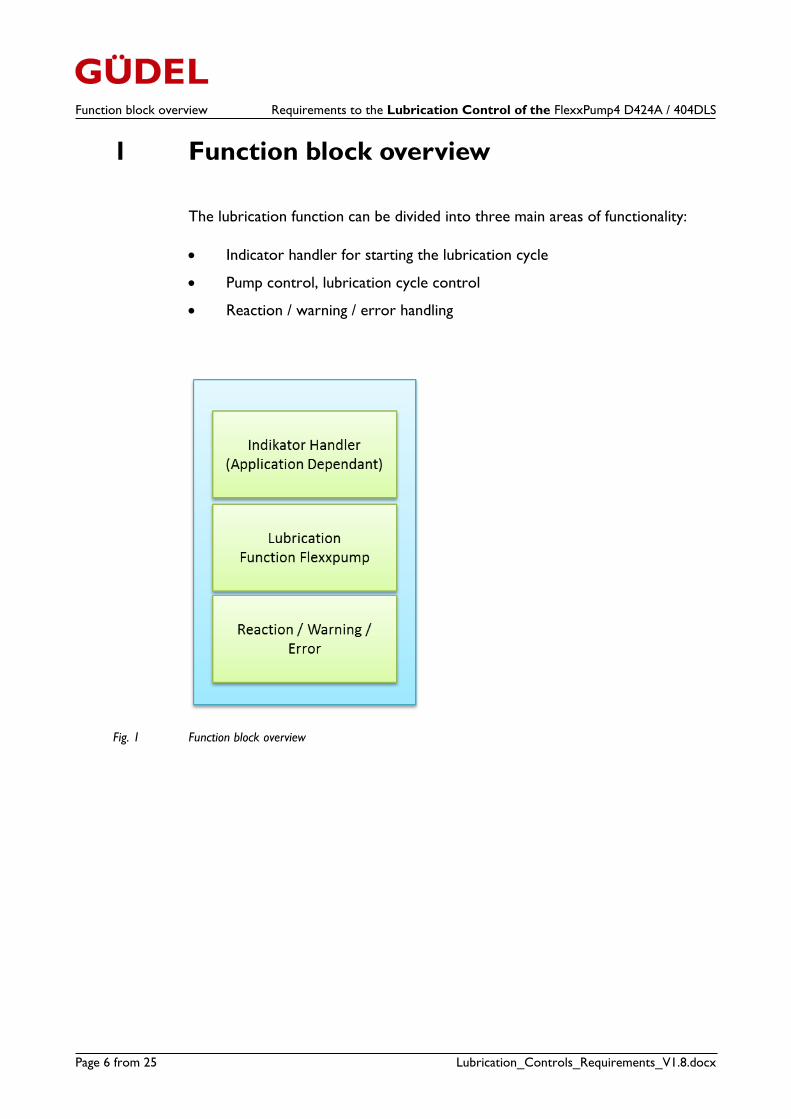
1 Function block overview
The lubrication function can be divided into three main areas of functionality:
Indicator handler for starting the lubrication cycle
Pump control, lubrication cycle control
Reaction / warning / error handling
Fig. 1 Function block overview
Requirements to the Lubrication Control of the FlexxPump4 D424A / 404DLS Function block overview
24.10.2017 Page 7 from 25
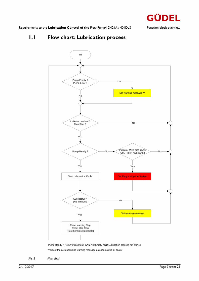
1.1 Flow chart: Lubrication process
Fig. 2 Flow chart
Init
Indikator reached ?
Man Start ?
Successful ?
(No Timeout)
Yes
No
Yes
Set Flag to stop the SystemStart Lubrication Cycle
Reset warning Flag
Reset stop Flag
(No other Reset possible)
Pump Empty ?
Pump Error ?
Set warning message **
Pump Ready ?
Yes
Yes
NoIndicator (Axis dist, Cycle
Cnt, Timer) has started
Yes
Set warning message
Pump Ready = No Error (5s Input) AND Not Empty AND Lubrication process not started
No
No
No
** Reset the corresponding warning message as soon as it is ok again
Interface description: Function blockRequirements to the Lubrication Control of the FlexxPump4 D424A / 404DLS
Page 8 from 25 Lubrication_Controls_Requirements_V1.8.docx
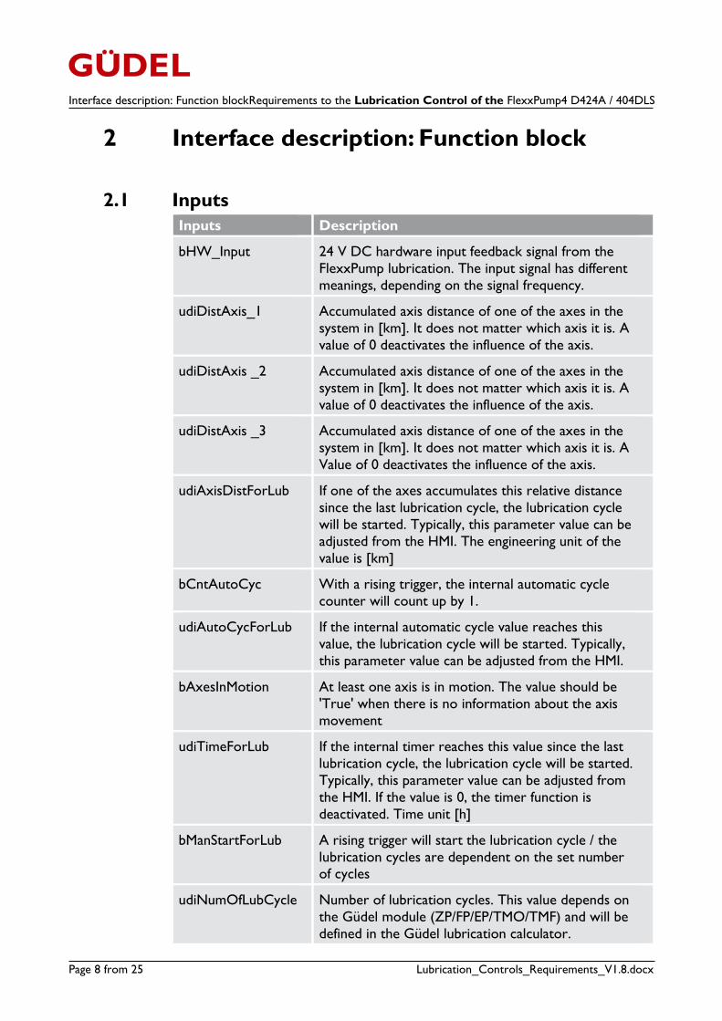
2 Interface description: Function block
2.1 Inputs
Inputs Description
bHW_Input 24 V DC hardware input feedback signal from the
FlexxPump lubrication. The input signal has different
meanings, depending on the signal frequency.
udiDistAxis_1 Accumulated axis distance of one of the axes in the
system in [km]. It does not matter which axis it is. A
value of 0 deactivates the influence of the axis.
udiDistAxis _2 Accumulated axis distance of one of the axes in the
system in [km]. It does not matter which axis it is. A
value of 0 deactivates the influence of the axis.
udiDistAxis _3 Accumulated axis distance of one of the axes in the
system in [km]. It does not matter which axis it is. A
Value of 0 deactivates the influence of the axis.
udiAxisDistForLub If one of the axes accumulates this relative distance
since the last lubrication cycle, the lubrication cycle
will be started. Typically, this parameter value can be
adjusted from the HMI. The engineering unit of the
value is [km]
bCntAutoCyc With a rising trigger, the internal automatic cycle
counter will count up by 1.
udiAutoCycForLub If the internal automatic cycle value reaches this
value, the lubrication cycle will be started. Typically,
this parameter value can be adjusted from the HMI.
bAxesInMotion At least one axis is in motion. The value should be
'True' when there is no information about the axis
movement
udiTimeForLub If the internal timer reaches this value since the last
lubrication cycle, the lubrication cycle will be started.
Typically, this parameter value can be adjusted from
the HMI. If the value is 0, the timer function is
deactivated. Time unit [h]
bManStartForLub A rising trigger will start the lubrication cycle / the
lubrication cycles are dependent on the set number of cycles
udiNumOfLubCycle Number of lubrication cycles. This value depends on
the Güdel module (ZP/FP/EP/TMO/TMF) and will be
defined in the Güdel lubrication calculator.
Requirements to the Lubrication Control of the FlexxPump4 D424A / 404DLSInterface description: Function block
24.10.2017 Page 9 from 25
Inputs Description
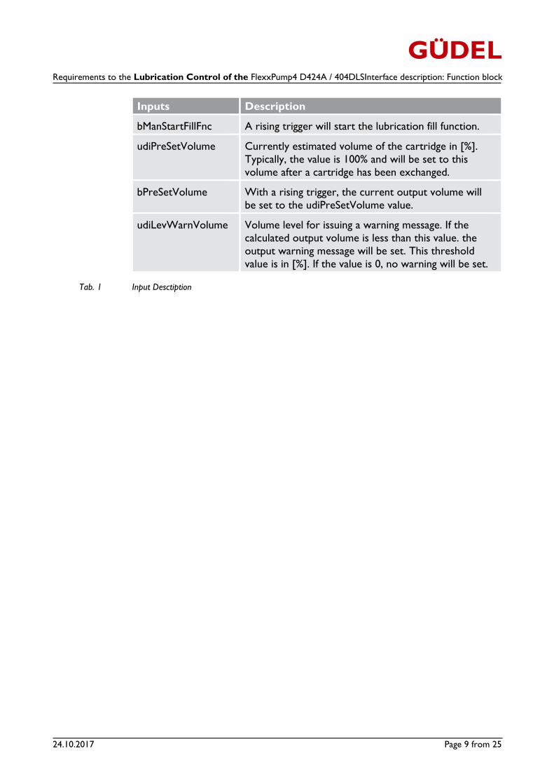
bManStartFillFnc A rising trigger will start the lubrication fill function.
udiPreSetVolume Currently estimated volume of the cartridge in [%].
Typically, the value is 100% and will be set to this
volume after a cartridge has been exchanged.
bPreSetVolume With a rising trigger, the current output volume will
be set to the udiPreSetVolume value.
udiLevWarnVolume Volume level for issuing a warning message. If the
calculated output volume is less than this value. the
output warning message will be set. This threshold
value is in [%]. If the value is 0, no warning will be set.
Tab. 1 Input Desctiption
Interface description: Function blockRequirements to the Lubrication Control of the FlexxPump4 D424A / 404DLS
Page 10 from 25 Lubrication_Controls_Requirements_V1.8.docx
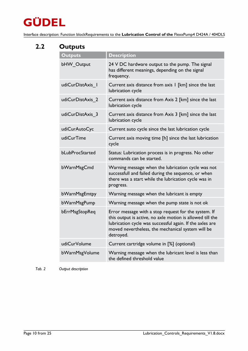
2.2 Outputs
Outputs Description
bHW_Output 24 V DC hardware output to the pump. The signal
has different meanings, depending on the signal
frequency.
udiCurDistAxis_1 Current axis distance from axis 1 [km] since the last
lubrication cycle
udiCurDistAxis_2 Current axis distance from Axis 2 [km] since the last
lubrication cycle
udiCurDistAxis_3 Current axis distance from Axis 3 [km] since the last
lubrication cycle
udiCurAutoCyc Current auto cycle since the last lubrication cycle
udiCurTime Current axis moving time [h] since the last lubrication
cycle
bLubProcStarted Status: Lubrication process is in progress. No other
commands can be started.
bWarnMsgCmd Warning message when the lubrication cycle was not
successfull and failed during the sequence, or when
there was a start while the lubrication cycle was in
progress.
bWarnMsgEmtpy Warning message when the lubricant is empty
bWarnMsgPump Warning message when the pump state is not ok
bErrMsgStopReq Error message with a stop request for the system. If
this output is active, no axle motion is allowed till the
lubrication cycle was successful again. If the axles are
moved nevertheless, the mechanical system will be
detroyed.
udiCurVolume Current cartridge volume in [%] (optional)
bWarnMsgVolume Warning message when the lubricant level is less than
the defined threshold value
Tab. 2 Output description
Requirements to the Lubrication Control of the FlexxPump4 D424A / 404DLS Detailed description of functions
24.10.2017 Page 11 from 25
3 Detailed description of functions
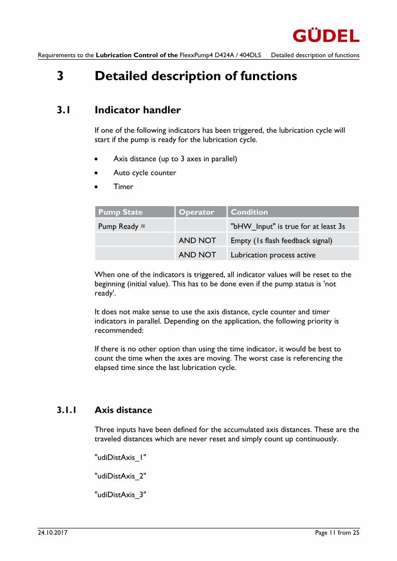
3.1 Indicator handler
If one of the following indicators has been triggered, the lubrication cycle will
start if the pump is ready for the lubrication cycle.
Axis distance (up to 3 axes in parallel)
Auto cycle counter
Timer
Pump State Operator Condition
Pump Ready = "bHW_Input" is true for at least 3s
AND NOT Empty (1s flash feedback signal)
AND NOT Lubrication process active
When one of the indicators is triggered, all indicator values will be reset to the
beginning (initial value). This has to be done even if the pump status is 'not
ready'.
It does not make sense to use the axis distance, cycle counter and timer
indicators in parallel. Depending on the application, the following priority is
recommended:
If there is no other option than using the time indicator, it would be best to
count the time when the axes are moving. The worst case is referencing the
elapsed time since the last lubrication cycle.
3.1.1 Axis distance
Three inputs have been defined for the accumulated axis distances. These are the
traveled distances which are never reset and simply count up continuously.
"udiDistAxis_1"
"udiDistAxis_2"
"udiDistAxis_3"
Detailed description of functions Requirements to the Lubrication Control of the FlexxPump4 D424A / 404DLS
Page 12 from 25 Lubrication_Controls_Requirements_V1.8.docx
It is not necessary to use all three inputs. This depends on the number of
relevant axes which are involved in the lubrication system. If an input is set to 0,
it does not influence the logic for the lubrication cycle.
Internally, the difference to a persistent distance variable will be calculated for
each axis.
E.g: DifferenceAxis_1 = "udiDistAxis_1" - udiDistToLastLubcycleAxis_1
As soon as one of the three differences is bigger than or equal to the threshold
value "udiAxisDistForLub", the lubrication cycle will be triggered. With the same
trigger, all persistent variables udiDistToLastLubcycleAxis_1,
udiDistToLastLubcycleAxis_2 and udiDistToLastLubcycleAxis_3 will be set to its
current distance input "udiDistAxis_1", "udiDistAxis_2" and "udiDistAxis_3"
The other indicators (automatic cycle counter and timer) must be reset as well.
Note
To not influence the system after a controller restart, the internal
distances moved since the last lubrication cycle,
udiDistToLastLubcycleAxis_1,2,3, should be stored as persistent values.
(As long as the input distance is persistent as well)
3.1.2 Automatic cycle counter
In some applications, it makes sense to count up the automatic cycles of the
system. A rising trigger of the input value "bCntAutoCyc" will increment an
internal persistent automatic cycle counter value by 1. If the counter value is
bigger than or equal to the threshold value "udiAutoCycForLub", the lubrication
cycle will be triggered. With the same trigger, the counter value will be reset to
0. The other indicators (axis distance and timer) must be reset as well.
Note
To not influence the system after a controller restart, the automatic
cycle counter value should be stored as a persistent value.
Requirements to the Lubrication Control of the FlexxPump4 D424A / 404DLS Detailed description of functions
24.10.2017 Page 13 from 25
3.1.3 Timer
The timer is only to be used when it is not possible to get the axis distance or
the automatic cycle counter. If possible, the timer should at least be dependent
on the axis movement. (No counting during stop). In the worst case, when there
is no information about the axis movement, the elapsed time since the last
lubrication cycle is to be used. An internal persistent timer should be started as
soon as the input "bAxesInMotion" is true. If the elapsed time is bigger than or
equal to the threshold value "udiTimeForLub", the lubrication cycle will be
triggered. With the same trigger, the timer will be reset. The other indicators
(axis distance and automatic cycle counter) must be reset as well.
Note
To not influence the system after a controller restart, the elapsed time
should be stored as a persistent value.
3.1.4 Manual start
Typically, checking the lubrication function during commissioning or service work requires a manual start of the lubrication cycle. With the rising trigger of the
input value "bManStartForLub", the lubrication cycle will be started. With the
same trigger, the other indicators (axis distance, automatic cycle counter and
timer) need to be reset.
Detailed description of functions Requirements to the Lubrication Control of the FlexxPump4 D424A / 404DLS
Page 14 from 25 Lubrication_Controls_Requirements_V1.8.docx
3.2 Lubrication function of the FlexxPump
Several lubrication cycles can be triggered on the FlexxPump. In the case of the Güdel application, the functions will be reduced to two sensible ones. One is the
fill function (used to fill up the lubricant points) and the other is the normal
lubrication cycle where both pump pistons are triggered forward and backward;
this means a discharge at all 4 outputs. Other controls make no sense and are
also not matched with the hydraulic design.
3.2.1 Normal lubrication cycle
If one of the indicators, i.e. axis distance, automatic cycle counter, timer or the
manual start "bManStartForLub", is triggered, the lubrication cycle can be started
when the pump is in a ready state.
Pump State Operator Condition
Pump Ready = "bHW_Input" is true for at least 3s
AND NOT Empty (1s flash feedback signal)
AND NOT Lubrication process active
If one of the conditions is not met, and a start trigger occurs, the flag
"bWarnMsgCmd" must be set. If one of the conditions is not met and one of the
indicators, i.e. axis distance, automatic cycle counter or timer, triggered the
cycle, the flag " bErrMsgStopReq" must also has to be set. (Chap. 3.3)
Depending on the module size and the mechanical design, it is possible that
several consecutive lubrication cycles (multiple actuations of all 4 outputs) are
necessary. The number of lubrication cycles needed can be determined with the
lubrication amount calculator.
LubricationCalculator
Requirements to the Lubrication Control of the FlexxPump4 D424A / 404DLS Detailed description of functions
24.10.2017 Page 15 from 25
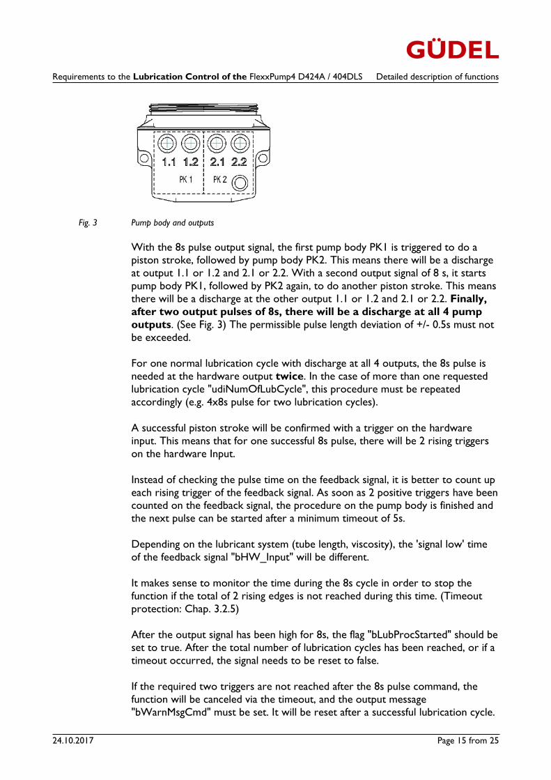
Fig. 3 Pump body and outputs
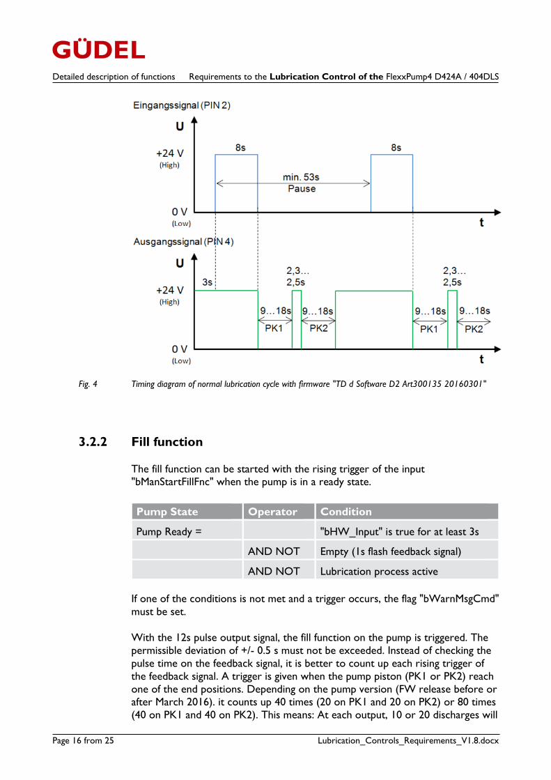
With the 8s pulse output signal, the first pump body PK1 is triggered to do a
piston stroke, followed by pump body PK2. This means there will be a discharge
at output 1.1 or 1.2 and 2.1 or 2.2. With a second output signal of 8 s, it starts
pump body PK1, followed by PK2 again, to do another piston stroke. This means
there will be a discharge at the other output 1.1 or 1.2 and 2.1 or 2.2. Finally,
after two output pulses of 8s, there will be a discharge at all 4 pump
outputs. (See Fig. 3) The permissible pulse length deviation of +/- 0.5s must not
be exceeded.
For one normal lubrication cycle with discharge at all 4 outputs, the 8s pulse is
needed at the hardware output twice. In the case of more than one requested
lubrication cycle "udiNumOfLubCycle", this procedure must be repeated
accordingly (e.g. 4x8s pulse for two lubrication cycles).
A successful piston stroke will be confirmed with a trigger on the hardware
input. This means that for one successful 8s pulse, there will be 2 rising triggers
on the hardware Input.
Instead of checking the pulse time on the feedback signal, it is better to count up
each rising trigger of the feedback signal. As soon as 2 positive triggers have been counted on the feedback signal, the procedure on the pump body is finished and
the next pulse can be started after a minimum timeout of 5s.
Depending on the lubricant system (tube length, viscosity), the 'signal low' time
of the feedback signal "bHW_Input" will be different.
It makes sense to monitor the time during the 8s cycle in order to stop the
function if the total of 2 rising edges is not reached during this time. (Timeout
protection: Chap. 3.2.5)
After the output signal has been high for 8s, the flag "bLubProcStarted" should be
set to true. After the total number of lubrication cycles has been reached, or if a
timeout occurred, the signal needs to be reset to false.
If the required two triggers are not reached after the 8s pulse command, the
function will be canceled via the timeout, and the output message
"bWarnMsgCmd" must be set. It will be reset after a successful lubrication cycle.
Detailed description of functions Requirements to the Lubrication Control of the FlexxPump4 D424A / 404DLS
Page 16 from 25 Lubrication_Controls_Requirements_V1.8.docx
Fig. 4 Timing diagram of normal lubrication cycle with firmware "TD d Software D2 Art300135 20160301"
3.2.2 Fill function
The fill function can be started with the rising trigger of the input "bManStartFillFnc" when the pump is in a ready state.
Pump State Operator Condition
Pump Ready = "bHW_Input" is true for at least 3s
AND NOT Empty (1s flash feedback signal)
AND NOT Lubrication process active
If one of the conditions is not met and a trigger occurs, the flag "bWarnMsgCmd"
must be set.
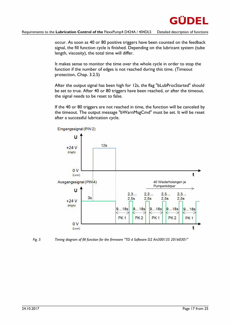
With the 12s pulse output signal, the fill function on the pump is triggered. The
permissible deviation of +/- 0.5 s must not be exceeded. Instead of checking the
pulse time on the feedback signal, it is better to count up each rising trigger of
the feedback signal. A trigger is given when the pump piston (PK1 or PK2) reach
one of the end positions. Depending on the pump version (FW release before or after March 2016). it counts up 40 times (20 on PK1 and 20 on PK2) or 80 times
(40 on PK1 and 40 on PK2). This means: At each output, 10 or 20 discharges will
Requirements to the Lubrication Control of the FlexxPump4 D424A / 404DLS Detailed description of functions
24.10.2017 Page 17 from 25
occur. As soon as 40 or 80 positive triggers have been counted on the feedback
signal, the fill function cycle is finished. Depending on the lubricant system (tube
length, viscosity), the total time will differ.
It makes sense to monitor the time over the whole cycle in order to stop the
function if the number of edges is not reached during this time. (Timeout
protection, Chap. 3.2.5)
After the output signal has been high for 12s, the flag "bLubProcStarted" should
be set to true. After 40 or 80 triggers have been reached, or after the timeout,
the signal needs to be reset to false.
If the 40 or 80 triggers are not reached in time, the function will be canceled by
the timeout. The output message "bWarnMsgCmd" must be set. It will be reset
after a successful lubrication cycle.
Fig. 5 Timing diagram of fill function for the firmware "TD d Software D2 Art300135 20160301"
Detailed description of functions Requirements to the Lubrication Control of the FlexxPump4 D424A / 404DLS
Page 18 from 25 Lubrication_Controls_Requirements_V1.8.docx
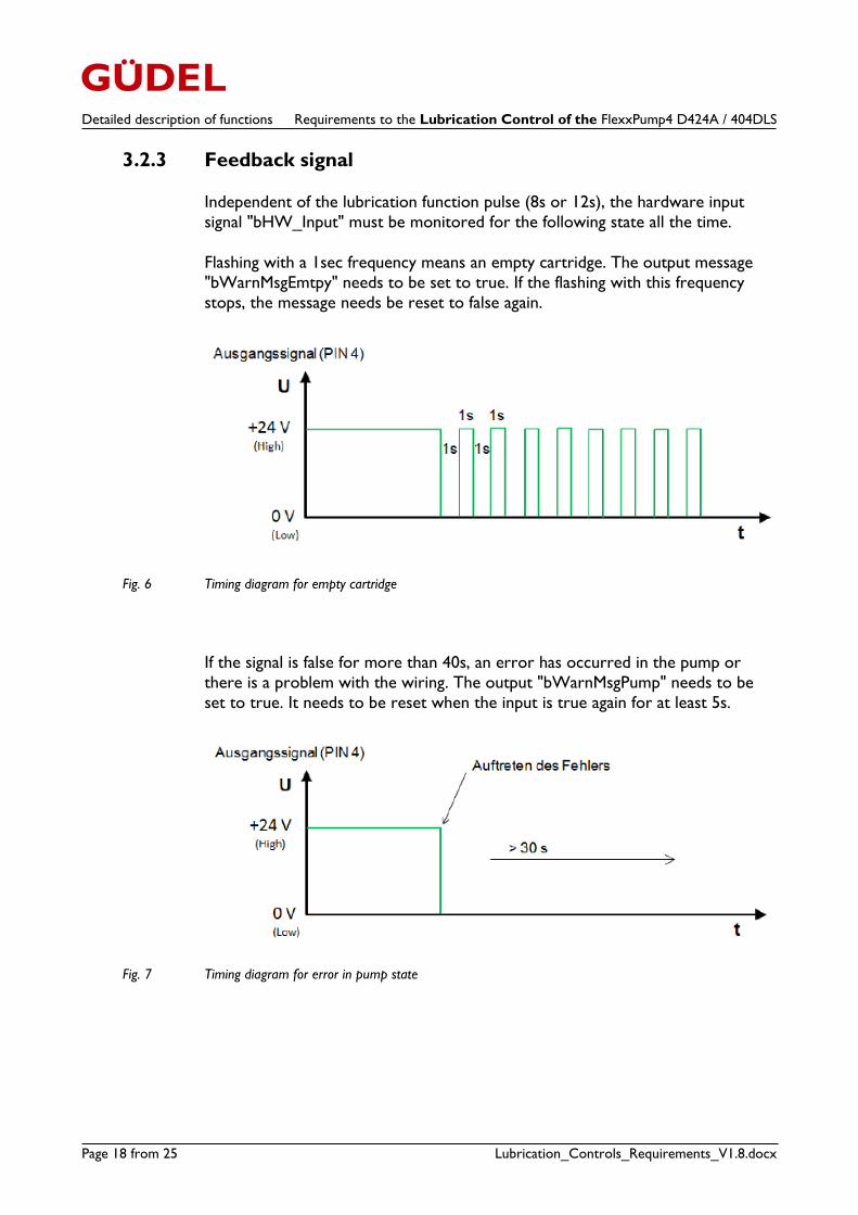
3.2.3 Feedback signal
Independent of the lubrication function pulse (8s or 12s), the hardware input
signal "bHW_Input" must be monitored for the following state all the time.
Flashing with a 1sec frequency means an empty cartridge. The output message
"bWarnMsgEmtpy" needs to be set to true. If the flashing with this frequency
stops, the message needs be reset to false again.
Fig. 6 Timing diagram for empty cartridge
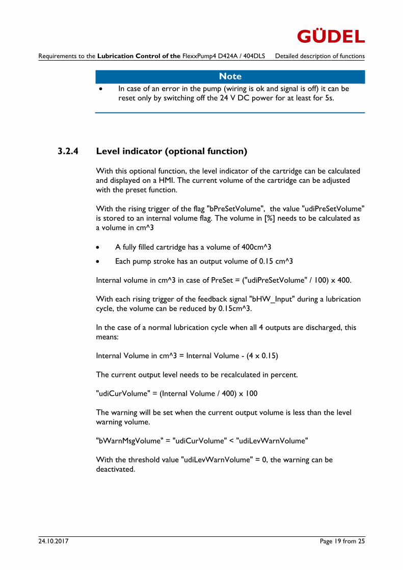
If the signal is false for more than 40s, an error has occurred in the pump or
there is a problem with the wiring. The output "bWarnMsgPump" needs to be
set to true. It needs to be reset when the input is true again for at least 5s.
Fig. 7 Timing diagram for error in pump state
Requirements to the Lubrication Control of the FlexxPump4 D424A / 404DLS Detailed description of functions
24.10.2017 Page 19 from 25
Note
In case of an error in the pump (wiring is ok and signal is off) it can be
reset only by switching off the 24 V DC power for at least for 5s.
3.2.4 Level indicator (optional function)
With this optional function, the level indicator of the cartridge can be calculated and displayed on a HMI. The current volume of the cartridge can be adjusted
with the preset function.
With the rising trigger of the flag "bPreSetVolume", the value "udiPreSetVolume"
is stored to an internal volume flag. The volume in [%] needs to be calculated as
a volume in cm^3
A fully filled cartridge has a volume of 400cm^3
Each pump stroke has an output volume of 0.15 cm^3
Internal volume in cm^3 in case of PreSet = ("udiPreSetVolume" / 100) x 400.
With each rising trigger of the feedback signal "bHW_Input" during a lubrication
cycle, the volume can be reduced by 0.15cm^3.
In the case of a normal lubrication cycle when all 4 outputs are discharged, this
means:
Internal Volume in cm^3 = Internal Volume - (4 x 0.15)
The current output level needs to be recalculated in percent.
"udiCurVolume" = (Internal Volume / 400) x 100
The warning will be set when the current output volume is less than the level
warning volume.
"bWarnMsgVolume" = "udiCurVolume" < "udiLevWarnVolume"
With the threshold value "udiLevWarnVolume" = 0, the warning can be
deactivated.
Detailed description of functions Requirements to the Lubrication Control of the FlexxPump4 D424A / 404DLS
Page 20 from 25 Lubrication_Controls_Requirements_V1.8.docx
3.2.5 Recommended constant values
5s "bHW_Input" high before a command pulse can start a lubrication cycle.
"bWarnMsgPump" when "bHW_Input" is false for more than 40s.
Timeout protection for normal lubrication cycle 53s after rising trigger of the 8s pulse (two times for the whole lubrication cycle)
Timeout protection for fill function 1660s after rising trigger of the 12s
pulse
Time between two rising triggers for the empty detection: 1.9s to 2.1s
3.3 Reaction / warning / error
bWarnMsgCmd:
Warning message when the lubrication cycle was not completed successfully.
E.g.: Number of triggers of the feedback signal was not reached in time (as described in Chapter 3.2.1 and 3.2.2). Or when there is a pump cycle start
request and the pump is not in a ready state.
Pump State Operator Condition
Pump Ready = "bHW_Input" is true for at least 3s
AND NOT Empty (1s flash feedback signal)
AND NOT Lubrication process active
After a successful lubrication cycle (normal or fill), the warning can be reset. The
warning just provides the information that something happened with the
lubrication; no system reaction is required.
bWarnMsgEmtpy:
The hardware input signal "bHW_Input" needs to monitored constantly for a 1s
flash frequency. As long as there is a 1s flash, the warning needs to be set. (See
Chap. 3.2.3). The warning just provides the information that something happened
with the lubrication; no system reaction is required.
Requirements to the Lubrication Control of the FlexxPump4 D424A / 404DLS Detailed description of functions
24.10.2017 Page 21 from 25
bWarnMsgPump:
The hardware input signal "bHW_Input" needs to be monitored for a true state
all the time. If its state is false for longer than 40s, the warning needs to be set
(see Chap. 3.2.3). The warning just provides the information that something
happened with the lubrication; no system reaction is required.
bErrMsgStopReq:
If one of the indicators (axis distance, automatic cycle or timer) requires a start
of the lubrication cycle and the cycle failed (pump not ready), this error message
needs to be set.
Pump State Operator Condition
Pump Ready = "bHW_Input" is true for at least 3s
AND NOT Empty (1s flash feedback signal)
AND NOT Lubrication process active
It is not required to set it by manual start of the lubrication cycle. After a
successful lubrication cycle (normal or fill) the "bErrMsgStopReq" needs to be reset.
Danger
With this error message, the involved axis of the lubrication system needs to be stopped. Typically, this will be done with a cycle stop and a
corresponding error message.
If the customer nevertheless wants to produce with the system, the stop request
mentioned above can only be ignored by a trained maintenance staff member
using a key switch or a password-protected button. A message must be shown
with the information that the mechanical system will be destroyed if the
lubrication function is not running well. The plant operator is responsible for
manual and sufficient lubrication.
Sample of an HMI screen Requirements to the Lubrication Control of the FlexxPump4 D424A / 404DLS
Page 22 from 25 Lubrication_Controls_Requirements_V1.8.docx
4 Sample of an HMI screen
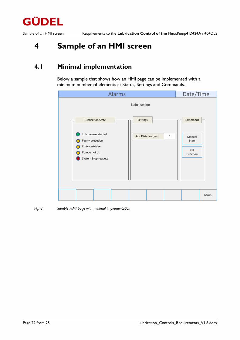
4.1 Minimal implementation
Below a sample that shows how an HMI page can be implemented with a
minimum number of elements at Status, Settings and Commands.
Fig. 8 Sample HMI page with minimal implementation
Alarms Date/Time
Lubrication
Main
Manual Start
CommandsLubrication State
Faulty execution
System Stop request
Lub process started
Settings
0
Emty cartridge
Pumpe not ok
Axis Distance [km]
FillFunction
Requirements to the Lubrication Control of the FlexxPump4 D424A / 404DLS Sample of an HMI screen
24.10.2017 Page 23 from 25
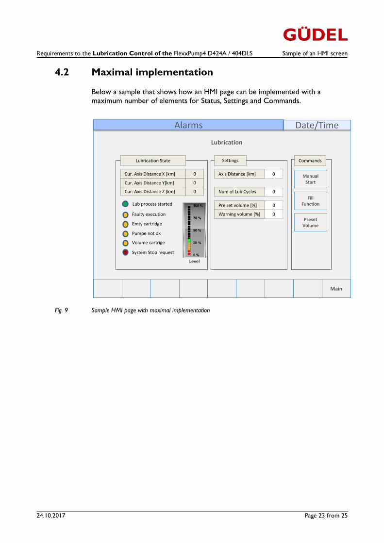
4.2 Maximal implementation
Below a sample that shows how an HMI page can be implemented with a maximum number of elements for Status, Settings and Commands.
Fig. 9 Sample HMI page with maximal implementation
Alarms Date/Time
Lubrication
Main
Manual Start
CommandsLubrication State
Faulty execution
System Stop request
Lub process started
Settings
Emty cartridge
Pumpe not ok
Volume cartrige
Level
0Num of Lub Cycles
0Pre set volume [%]
0Warning volume [%]
FillFunction
PresetVolume
0Axis Distance [km]0Cur. Axis Distance X [km]
0Cur. Axis Distance Y[km]
0Cur. Axis Distance Z [km]
Sample of an HMI screen Requirements to the Lubrication Control of the FlexxPump4 D424A / 404DLS
Page 24 from 25 Lubrication_Controls_Requirements_V1.8.docx
Version V1.8 Autor chrvet
GÜDEL AG
Industrie Nord
CH-4900 Langenthal
Switzerland
phone +41 (0)62 916 91 91
fax +41 (0)62 916 91 50
eMail [email protected]
www.gudel.com
Requirements to the Lubrication Control of the FlexxPump4 D424A / 404DLS Sample of an HMI screen
24.10.2017 Page 25 from 25
GÜDEL AG
Industrie Nord
CH-4900 Langenthal
Switzerland
Phone +41 (0)62 916 91 91
www.gudel.com