Embed Size (px)
Citation preview
Modeling
Simulation
Implementation
User’s GuideVersion 1
For Use with Simulink®
RequirementsManagement Interface

How to Contact The MathWorks:
508-647-7000 Phone
508-647-7001 Fax
The MathWorks, Inc. Mail3 Apple Hill DriveNatick, MA 01760-2098
http://www.mathworks.com Webftp.mathworks.com Anonymous FTP servercomp.soft-sys.matlab Newsgroup
[email protected] Technical [email protected] Product enhancement [email protected] Bug [email protected] Documentation error [email protected] Subscribing user [email protected] Order status, license renewals, [email protected] Sales, pricing, and general information
Requirements Management Interface User’s Guide COPYRIGHT 2000 by The MathWorks, Inc.The software described in this document is furnished under a license agreement. The software may be usedor copied only under the terms of the license agreement. No part of this manual may be photocopied or repro-duced in any form without prior written consent from The MathWorks, Inc.
FEDERAL ACQUISITION: This provision applies to all acquisitions of the Program and Documentation byor for the federal government of the United States. By accepting delivery of the Program, the governmenthereby agrees that this software qualifies as "commercial" computer software within the meaning of FARPart 12.212, DFARS Part 227.7202-1, DFARS Part 227.7202-3, DFARS Part 252.227-7013, and DFARS Part252.227-7014. The terms and conditions of The MathWorks, Inc. Software License Agreement shall pertainto the government’s use and disclosure of the Program and Documentation, and shall supersede anyconflicting contractual terms or conditions. If this license fails to meet the government’s minimum needs oris inconsistent in any respect with federal procurement law, the government agrees to return the Programand Documentation, unused, to MathWorks.
MATLAB, Simulink, Stateflow, Handle Graphics, and Real-Time Workshop are registered trademarks, andTarget Language Compiler is a trademark of The MathWorks, Inc.
Other product or brand names are trademarks or registered trademarks of their respective holders.
Printing History: January 2000 First printing New for Version 1 (Release 11)September 2000Online only Updated for Version 1 (Release 12)

iii
Contents
Preface
What the Requirements Management Interface Is . . . . . . . viiiFeatures . . . . . . . . . . . . . . . . . . . . . . . . . . . . . . . . . . . . . . . . . . . . viii
Related Products . . . . . . . . . . . . . . . . . . . . . . . . . . . . . . . . . . . . . . ix
Using This Guide . . . . . . . . . . . . . . . . . . . . . . . . . . . . . . . . . . . . . . . xExpected Background . . . . . . . . . . . . . . . . . . . . . . . . . . . . . . . . . . . xOrganization of the Document . . . . . . . . . . . . . . . . . . . . . . . . . . . xiExamples Used . . . . . . . . . . . . . . . . . . . . . . . . . . . . . . . . . . . . . . . xi
Configuration Information . . . . . . . . . . . . . . . . . . . . . . . . . . . . xivSystem Requirements . . . . . . . . . . . . . . . . . . . . . . . . . . . . . . . . . xivInstallation . . . . . . . . . . . . . . . . . . . . . . . . . . . . . . . . . . . . . . . . . . xiv
Typographical Conventions . . . . . . . . . . . . . . . . . . . . . . . . . . . xvi
1Using the Requirements Management Interface
Overview of the Process . . . . . . . . . . . . . . . . . . . . . . . . . . . . . . . 1-2Summary of Steps to Use the Requirements ManagementInterface . . . . . . . . . . . . . . . . . . . . . . . . . . . . . . . . . . . . . . . . . . . . 1-3
Startup . . . . . . . . . . . . . . . . . . . . . . . . . . . . . . . . . . . . . . . . . . . . . . 1-4
Opening an Object in the Navigator . . . . . . . . . . . . . . . . . . . . 1-5Stateflow Charts and M-Files in the Navigator . . . . . . . . . . . . 1-6

iv Contents
Adding Requirements . . . . . . . . . . . . . . . . . . . . . . . . . . . . . . . . . 1-9About the Requirements Documents . . . . . . . . . . . . . . . . . . . . . 1-9How To Add a Requirement . . . . . . . . . . . . . . . . . . . . . . . . . . . . 1-9
Viewing Requirements in the Navigator . . . . . . . . . . . . . . . . 1-13Indication of Requirements . . . . . . . . . . . . . . . . . . . . . . . . . . . . 1-13Viewing the Requirements for a Node . . . . . . . . . . . . . . . . . . . 1-17Changing or Deleting a Requirement . . . . . . . . . . . . . . . . . . . . 1-17Changing the View in the Navigator . . . . . . . . . . . . . . . . . . . . 1-17Going to the Requirements Document . . . . . . . . . . . . . . . . . . . 1-19Going from the Navigator to an Object . . . . . . . . . . . . . . . . . . . 1-20Highlighting Subsystems and Blocks That HaveRequirements . . . . . . . . . . . . . . . . . . . . . . . . . . . . . . . . . . . . . . . 1-21
2Using the Requirements Management Interface for
QSS’s DOORS
Overview of the Process . . . . . . . . . . . . . . . . . . . . . . . . . . . . . . . 2-2Summary of Steps to Use the Requirements ManagementInterface . . . . . . . . . . . . . . . . . . . . . . . . . . . . . . . . . . . . . . . . . . . . 2-3
Startup . . . . . . . . . . . . . . . . . . . . . . . . . . . . . . . . . . . . . . . . . . . . . . . 2-5
Opening an Object in the Navigator . . . . . . . . . . . . . . . . . . . . 2-7Stateflow Charts and MATLAB M-Files in the Navigator . . . . 2-8
Synchronizing the Navigator with DOORS . . . . . . . . . . . . . 2-11What Synchronizing Does and When to Synchronize . . . . . . . 2-11How to Synchronize . . . . . . . . . . . . . . . . . . . . . . . . . . . . . . . . . . 2-12Checking Synchronization . . . . . . . . . . . . . . . . . . . . . . . . . . . . . 2-14
Linking an Object to a DOORS Requirement . . . . . . . . . . . 2-16
v
Viewing Requirements in the Navigator . . . . . . . . . . . . . . . . 2-18Indication of Requirements . . . . . . . . . . . . . . . . . . . . . . . . . . . . 2-18Changing the View in the Navigator . . . . . . . . . . . . . . . . . . . . 2-23Going from the Navigator to DOORS . . . . . . . . . . . . . . . . . . . . 2-24Going from the Navigator to a MATLAB Object . . . . . . . . . . . 2-25Highlighting Subsystems and Blocks That HaveRequirements . . . . . . . . . . . . . . . . . . . . . . . . . . . . . . . . . . . . . . . 2-26
Going from DOORS to an Object . . . . . . . . . . . . . . . . . . . . . . . 2-28
Running a Script from DOORS . . . . . . . . . . . . . . . . . . . . . . . . 2-29
3 Reference

vi Contents
Preface
What the Requirements Management Interface Is . . . . viFeatures . . . . . . . . . . . . . . . . . . . . . . . vi
Related Products . . . . . . . . . . . . . . . . . . .vii
Using This Guide . . . . . . . . . . . . . . . . . . viiiExpected Background . . . . . . . . . . . . . . . . . viiiOrganization of the Document . . . . . . . . . . . . . . ixExamples Used . . . . . . . . . . . . . . . . . . . . ix
Configuration Information . . . . . . . . . . . . . .xiiSystem Requirements . . . . . . . . . . . . . . . . . .xiiInstallation . . . . . . . . . . . . . . . . . . . . . .xii
Typographical Conventions . . . . . . . . . . . . . xiv
Preface
viii
What the Requirements Management Interface IsThe Requirements Management Interface allows you to associaterequirements with Simulink® models, Stateflow® diagrams, and MATLAB®M-files. There is a standard version of the Requirements ManagementInterface and a version that works with the DOORS requirementsmanagement system, a product offering from Quality Systems & Software, Inc.(QSS).
For the standard version, the requirements are in HTML, Microsoft Word, andMicrosoft Excel documents. For the DOORS version, the requirements aremanaged by DOORS.
When you use the DOORS version of the Requirements Management Interfacefor a given model, diagram, or M-file, you can only associate it with DOORSrequirements (and not Word, Excel, or HTML requirements documents).Similarly, when you use the standard version of the RequirementsManagement Interface for a given model, diagram, or M-file, you can onlyassociate Word, Excel, and HTML requirements documents with it (and notDOORS requirements).
FeaturesUse the Requirements Management Interface to:
• Associate requirements with these objects:
- Simulink subsystems and blocks
- Stateflow charts, states, and transitions
- MATLAB M-files
• See which objects have requirements associated with them.
• Go from the Requirements Management Interface Navigator to arequirement.
• Go from a requirement in DOORS to a MATLAB object (for DOORS versiononly).
• Run a MATLAB script that executes a Simulink simulation or M-file fromDOORS (for DOORS version only).
Related Products
ix
Related ProductsThe Requirements Management Interface requires:
• MATLAB Version 5.3.1 or later
• Simulink Version 3.0.1 or later
• Stateflow Version 2.0.1 or later, if you want to use the RequirementsManagement Interface for Stateflow diagrams
For more information about any of these products, see either:
• The online documentation for that product if it is installed or if you arereading the documentation from the CD
• The MathWorks Web site, at http://www.mathworks.com; see the “products”section
Preface
x
Using This Guide
Expected BackgroundTo use the Requirements Management Interface:
• You must understand MATLAB, Simulink, or Stateflow.
• If you are using the standard version of the Requirements ManagementInterface, no special knowledge of Microsoft Word, Microsoft Excel, or HTMLdocuments is required.
• If you are using the DOORS version, you must have experience working withprojects and formal modules in DOORS.
Using This Guide
xi
Organization of the Document
Examples Used
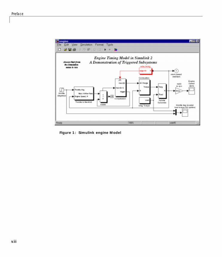
Simulink ExampleThis guide uses the Simulink enginemodel as the example object for Simulink.It is located in $matlabroot\toolbox\simulink\simdemos.
Section Description
“Using theRequirementsManagementInterface”
Instructions for using the standard version of theRequirements Management Interface. Use this toassociate Simulink models, Stateflow diagrams, andMATLAB M-files with requirements in HTML,Microsoft Word, and Microsoft Excel documents.
“Using theRequirementsManagementInterface forQSS’s DOORS”
Instructions for using the DOORS version of theRequirements Management Interface. Use this if youuse the DOORS requirements management system andwant to associate Simulink models, Stateflow diagrams,and MATLAB M-files with requirements in DOORS.
Preface
xii
Figure 1: Simulink engine Model

Using This Guide
xiii
Stateflow ExampleThis guide uses the fuelsys model as the example object for Stateflow. Themodel contains a Stateflow chart in the fuel rate controller. The fuelsysmodel is located in $matlabroot\toolbox\stateflow\sfdemos.
Figure 2: fuelsys Model with Stateflow Fuel Rate Controller Chart
MATLAB M-File ExampleThis guide uses an M-file engine.m as the example object for MATLAB. AnyM-file works the same way in the Requirements Management Interface.
Preface
xiv
Configuration Information
System RequirementsThe Requirements Management Interface works on:
• Microsoft Windows 95, Windows 98, and Windows NT systems
• UNIX systems where MATLAB supports Java (for HTML-basedrequirements documents only).
To use the Requirements Management Interface, you need the followingsoftware installed:
• MATLAB Version 5.3.1 or higher
• Simulink Version 3.0.1 or higher
• Stateflow Version 2.0.1 or higher, if you want to use the RequirementsManagement Interface for Stateflow diagrams
• For the standard version of the Requirements Management Interface, youneed the applications that you use to view your requirements documents.The following applications are supported:
- Microsoft Word 97 or higher
- Microsoft Excel 97 or higher
- Netscape Navigator Version 4.0 or higher, or Microsoft Internet ExplorerVersion 4.0 or higher for HTML documents
• For the DOORS version of the Requirements Management Interface, youneed QSS’s DOORS requirements management system, Version 4.0.3 orhigher.
InstallationYou use the standard MATLAB installation process to install theRequirements Management Interface. However, if you plan to use the DOORSversion of the Requirements Management Interface, you must installadditional files.
Additional Installation for DOORS Users
1 If DOORS is running, close DOORS.
Configuration Information
xv
2 Copy addins.idx and addins.hlp from $matlabroot\toolbox\reqmgt tothe <doors>\lib\dxl\addins directory. <doors> represents the top-leveldirectory where DOORS is installed. Replace any existing versions of thefiles if they have not been modified; otherwise, merge their contents.
3 Copy the following files from $matlabroot\toolbox\reqmgt to the<doors>\lib\dxl\addins\dmi directory. Replace any existing versions ofthe files.
dmi.hlp
dmi.idx
dmi.inc
runsim.dxl
selblk.dxl
4 Change the include path in the DOORS startup file. To do so:
a Open <doors>\lib\dxl\startup.dxl in an editor.
b In the user defined files section of startup.dxl, add the line
#include <addins/dmi/dmi.inc>
c Save startup.dxl and close it.

Preface
xvi
Typographical Conventions
Item Convention to Use Example
Function names/syntax Monospace font The cos function finds thecosine of each array element.
Syntax line example is
MLGetVar ML_var_name
Keys Boldface with an initialcapital letter
Press the Return key.
Menu names, menu items, andcontrols
Boldface with an initialcapital letter
Choose the File menu.
New terms Italics An array is an orderedcollection of information.
1Using the RequirementsManagement Interface
Overview of the Process . . . . . . . . . . . . . . 1-2Summary of Steps to Use the Requirements Management
Interface . . . . . . . . . . . . . . . . . . . . 1-3
Startup . . . . . . . . . . . . . . . . . . . . . . 1-4
Opening an Object in the Navigator . . . . . . . . . 1-5Stateflow Charts and M-Files in the Navigator . . . . . . 1-6
Adding Requirements . . . . . . . . . . . . . . . . 1-9About the Requirements Documents . . . . . . . . . . . 1-9How To Add a Requirement . . . . . . . . . . . . . . 1-9
Viewing Requirements in the Navigator . . . . . . . 1-13Indication of Requirements . . . . . . . . . . . . . . 1-13Viewing the Requirements for a Node . . . . . . . . . . 1-17Changing or Deleting a Requirement . . . . . . . . . . 1-17Changing the View in the Navigator . . . . . . . . . . . 1-17Going to the Requirements Document . . . . . . . . . . 1-19Going from the Navigator to an Object . . . . . . . . . . 1-20Highlighting Subsystems and Blocks That Have
Requirements . . . . . . . . . . . . . . . . . . 1-21

1 Using the Requirements Management Interface
1-2
Overview of the ProcessThis diagram depicts how the Requirements Management Interface associatesobjects with requirements documents.
Figure 1-1: How the Requirements Management Interface Works with Requirements Documents
ModelSubsystem
BlockBlock
SubsystemBlock
Block
BlockName of document (having requirements for selected block)
Location in document(phrase or anchor)
Content....
...
Requirement phrase or named anchorRequirement...
...
Object - Simulink Model,Stateflow Diagram, or MATLAB M-File Requirements Management Interface View of Object
Requirements Document
- Microsoft Word
- Microsoft Excel
- HTML
Simulink Model
MATLABSimulinkStateflow
Overview of the Process
1-3
Summary of Steps to Use the Requirements Management Interface
Step Description
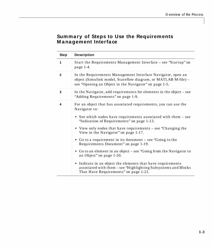
1 Start the Requirements Management Interface – see “Startup” onpage 1-4.
2 In the Requirements Management Interface Navigator, open anobject (Simulink model, Stateflow diagram, or MATLAB M-file) –see “Opening an Object in the Navigator” on page 1-5.
3 In the Navigator, add requirements for elements in the object – see“Adding Requirements” on page 1-9.
4 For an object that has associated requirements, you can use theNavigator to:
• See which nodes have requirements associated with them – see“Indication of Requirements” on page 1-13.
• View only nodes that have requirements – see “Changing theView in the Navigator” on page 1-17.
• Go to a requirement in its document – see “Going to theRequirements Document” on page 1-19.
• Go to an element in an object – see “Going from the Navigator toan Object” on page 1-20.
• Indicate in an object the elements that have requirementsassociated with them – see “Highlighting Subsystems and BlocksThat Have Requirements” on page 1-21.

1 Using the Requirements Management Interface
1-4
Startup1 Start MATLAB.
2 Edit the file $matlabroot\toolbox\reqmgt\reqmgropts.m to specify theOTHERS option for the Requirements Management Interface.
a Type edit reqmgropts at the MATLAB prompt.
The reqmgropts.m file opens in your editor.
b Edit the reqsys line so it appears as follows.
reqsys = 'OTHERS';
c Save reqmgropts.m and close it.
3 At the MATLAB prompt, type
rminav
or, in Simulink or Stateflow, select Requirements management interfacefrom the Tools menu.
The Navigator window opens.
Figure 1-2: Navigator – No Object Open

Opening an Object in the Navigator
1-5
Opening an Object in the NavigatorYou can use the current model or the file for another object. The object’s filemust be on the MATLAB path or in the current directory. To open an object:
• If the Simulink or Stateflow object you want to associate requirements withis already open and is the currently active model, selectOpen Current Model from the File menu in the Navigator.
• If the Simulink or Stateflow object you want to associate requirements withis not currently open, or if you want to associate requirements with aMATLAB M-file, use Open:
a Select Open from the File menu in the Navigator.
The Open Model/File dialog box appears.
b Select the object that you want to associate with requirements and clickOpen.
The object opens in Simulink or Stateflow.
Note While using the Navigator, do not close the model in Simulink.
For a Simulink or Stateflow object, the subsystems, blocks, charts, states, andtransitions appear as nodes in a hierarchical tree structure in the left pane ofthe Navigator. An M-file appears as a single node in the left pane of theNavigator.
1 Using the Requirements Management Interface
1-6
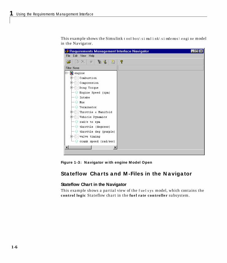
This example shows the Simulink toolbox\simulink\simdemos\enginemodelin the Navigator.
Figure 1-3: Navigator with engine Model Open
Stateflow Charts and M-Files in the Navigator
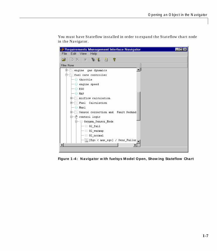
Stateflow Chart in the NavigatorThis example shows a partial view of the fuelsys model, which contains thecontrol logic Stateflow chart in the fuel rate controller subsystem.
Opening an Object in the Navigator
1-7
You must have Stateflow installed in order to expand the Stateflow chart nodein the Navigator.
Figure 1-4: Navigator with fuelsys Model Open, Showing Stateflow Chart
1 Using the Requirements Management Interface
1-8
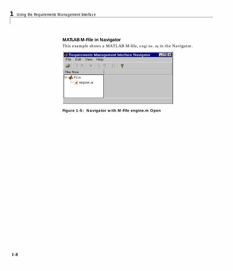
MATLAB M-File in NavigatorThis example shows a MATLAB M-file, engine.m, in the Navigator.
Figure 1-5: Navigator with M-File engine.m Open

Adding Requirements
1-9
Adding RequirementsAfter opening an object in the Navigator, you can associate a node in thehierarchical tree with requirements in documents. Then you can go from theNavigator to a requirement. You can associate multiple requirementsdocuments with a single node in the tree.
Note You must have write permission for an object in order to addrequirements. Adding a requirement automatically saves the model or M-file.
About the Requirements DocumentsThe requirements can be in Microsoft Word, Microsoft Excel, or HTMLdocuments.
• You can specify just the requirements document name. Then when you go toit from the Navigator, you will go to the top of that document.
• You can specify a specific location within the requirements document.
- For Word and Excel, the specific location is simply the first instance of agiven word in the requirements document.
- For HTML, the specific location is a named anchor, for example,<A href="valve_timing.html">.
How To Add a Requirement
1 Select the node you want to associate with a requirement. You can add arequirement to any node in the hierarchical tree.
If a node contains other nodes, click next to the node to expand it. You canthen select one of the nodes in the expanded hierarchical tree.
1 Using the Requirements Management Interface
1-10
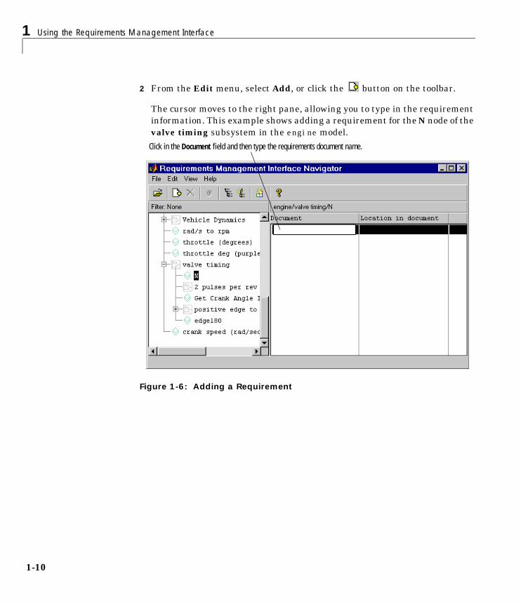
2 From the Edit menu, select Add, or click the button on the toolbar.
The cursor moves to the right pane, allowing you to type in the requirementinformation. This example shows adding a requirement for the N node of thevalve timing subsystem in the engine model.
Figure 1-6: Adding a Requirement
Click in the Document field and then type the requirements document name.

Adding Requirements
1-11
3 Click in the Document field in the right pane, type the full path for therequirements document, and press Enter.
Here are examples of full pathnames.
4 If the requirement is at a specific location within the document, you can addthe location. Otherwise, skip this step.
Double-click in the Location in document field, type the location, and thenpress Enter. An example location for any document type is valve_timing.
5 Repeat this process to add additional requirements for the same node or forother nodes.
Note If your Stateflow chart contains transitions that are not unique, do notassociate requirements with them.
Pathname For Document Type
c:\Requirements\Car Requirements.doc Word
d:\car_files\car_reqts.xls Excel
http://www-internal.com/carreqts.html HTML
file:///bserver/car/requirements.html HTML
1 Using the Requirements Management Interface
1-12
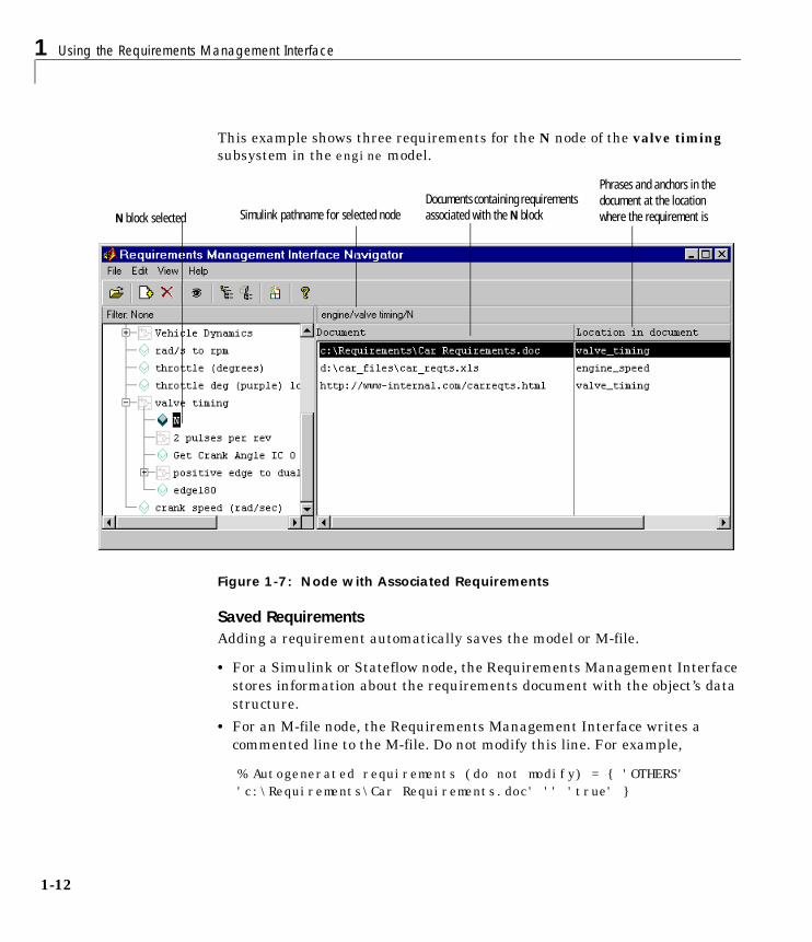
This example shows three requirements for the N node of the valve timingsubsystem in the engine model.
Figure 1-7: Node with Associated Requirements
Saved RequirementsAdding a requirement automatically saves the model or M-file.
• For a Simulink or Stateflow node, the Requirements Management Interfacestores information about the requirements document with the object’s datastructure.
• For an M-file node, the Requirements Management Interface writes acommented line to the M-file. Do not modify this line. For example,
% Autogenerated requirements (do not modify) = { 'OTHERS' 'c:\Requirements\Car Requirements.doc' '' 'true' }
N block selectedDocuments containing requirements associated with the N block
Phrases and anchors in the document at the location where the requirement isSimulink pathname for selected node

Viewing Requirements in the Navigator
1-13
Viewing Requirements in the NavigatorUse the Navigator to see which objects have requirements associated withthem.
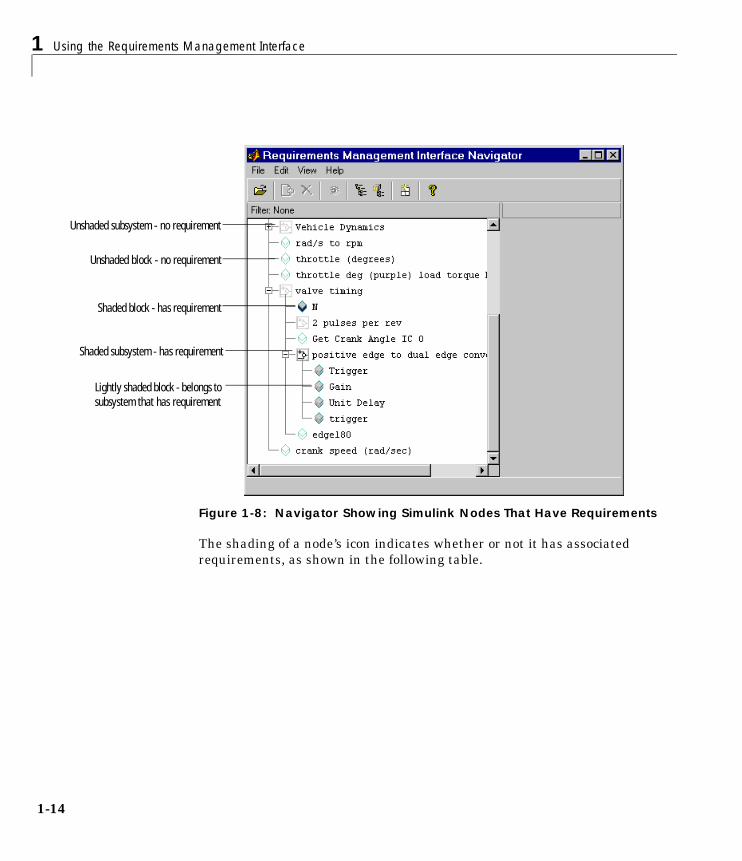
Indication of RequirementsAfter adding a requirement to a node, the shading of the node’s icon changes.In the Navigator, you can see which nodes have requirements associated withthem by the shading of the node’s icons.
The following example shows that nodes for the N block in the valve timingsubsystem and the positive edge to dual edge conversion subsystem areshaded, indicating they have requirements associated with them. The nodesunder the positive edge to dual edge conversion subsystem are lightlyshaded, indicating they belong to a subsystem that has requirementsassociated with it.
1 Using the Requirements Management Interface
1-14
Figure 1-8: Navigator Showing Simulink Nodes That Have Requirements
The shading of a node’s icon indicates whether or not it has associatedrequirements, as shown in the following table.
Shaded block - has requirement
Unshaded block - no requirement
Shaded subsystem - has requirement
Lightly shaded block - belongs to subsystem that has requirement
Unshaded subsystem - no requirement

Viewing Requirements in the Navigator
1-15
Table 1-1: Node Icons in Navigator and What They Represent
Node Shading What It Represents
Not shaded Simulink subsystem with no requirements
Shaded Simulink subsystem that has requirements
Lightly shaded Simulink subsystem belonging to a subsystem that has requirements;subsystem itself has no requirements
Not shaded Simulink block with no requirements
Shaded Simulink block that has requirements
Lightly shaded Simulink block belonging to a subsystem that has requirements; blockitself has no requirements
Not shaded Stateflow chart with no requirements
Shaded Stateflow chart that has requirements
Lightly shaded Stateflow chart belonging to a subsystem that has requirements;chart itself has no requirements
Not shaded Stateflow state with no requirements
Shaded (withyellow)
Stateflow state that has requirements
Lightly shaded Stateflow state belonging to a superstate, chart, or subsystem thathas requirements; state itself has no requirements
Not shaded Stateflow transition with no requirements
Shaded (withblue)
Stateflow transition that has requirements
Lightly shaded Stateflow transition belonging to a superstate, chart, or subsystemthat has requirements; transition itself has no requirements
Not shaded MATLAB M-file with no requirements
Shaded MATLAB M-file that has requirements

1 Using the Requirements Management Interface
1-16
Stateflow Chart with RequirementsThis example shows the control logic Stateflow chart (in the fuel ratecontroller subsystem of the fuelsys model) with requirements.
Figure 1-9: Navigator for Stateflow Chart with Requirements
MATLAB M-File with RequirementsThis example shows the M-file engine.m with requirements.
Figure 1-10: Navigator for M-File with Requirements
Unshaded chart - no requirement
Shaded superstate - has requirement
Lightly shaded state - belongs to superstate that has requirement
Shaded transition - has its own requirement
Shaded M-file icon - has requirement
Viewing Requirements in the Navigator
1-17
Viewing the Requirements for a NodeSelect a node that has requirements associated with it. The requirements forthat node appear in the right pane of the Navigator.
Changing or Deleting a RequirementAfter adding a requirement in the Navigator, you can change the requirementsdocument or location, or you can delete the requirement.
Changing a Requirement
1 In the left pane, select the node whose requirement you want to change.
2 In the right pane, select the requirement you want to change.
3 From the Edit menu, select Replace to edit the Document field. Note thatdouble-clicking in this field opens the requirement document. To edit theLocation in document field, double-click in the field.
4 Type the changes in the Document and/or Location in document fields andthen press Enter.
Deleting a Requirement
1 In the left pane, select the node whose requirement you want to delete.
2 In the right pane, select the requirement you want to delete.
3 From the Edit menu, select Delete. Or click the button.
The requirement is removed and no longer appears.
Changing the View in the NavigatorIn the Navigator, you can change the view to:
• “Make Panes Wider or Narrower”
• “Show or Hide Lower Levels in the Tree”
• “Show Only the Highest Level in the Tree” hiding the lower levels
• “Show Only Nodes That Have Requirements” associated with them
1 Using the Requirements Management Interface
1-18
Make Panes Wider or NarrowerDrag the separator bar between the left and right panes in the Navigator tomake one of the panes wider and the other pane narrower. You can also adjustthe width of the Document and Location in document columns using theseparator between the column titles in the right pane.
You can make the overall window larger or smaller by dragging any edge of thewindow.
Show or Hide Lower Levels in the Tree
• Click to expand a node in the tree, which shows lower levels.
• Click to collapse a node in the tree, which hides the lower levels.
Show Only the Highest Level in the TreeFrom the View menu, select Refresh. This collapses the tree so that only thehighest level nodes are shown.
Show Only Nodes That Have RequirementsFrom the View menu, select Show Requirement Nodes or click thebutton.
Viewing Requirements in the Navigator
1-19
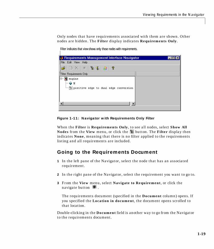
Only nodes that have requirements associated with them are shown. Othernodes are hidden. The Filter display indicates Requirements Only.
Figure 1-11: Navigator with Requirements Only Filter
When the Filter is Requirements Only, to see all nodes, select Show AllNodes from the View menu, or click the button. The Filter display thenindicates None, meaning that there is no filter applied to the requirementslisting and all requirements are included.
Going to the Requirements Document
1 In the left pane of the Navigator, select the node that has an associatedrequirement.
2 In the right pane of the Navigator, select the requirement you want to go to.
3 From the View menu, select Navigate to Requirement, or click thenavigate button .
The requirements document (specified in the Document column) opens. Ifyou specified the Location in document, the document opens scrolled tothat location.
Double-clicking in the Document field is another way to go from the Navigatorto the requirements document.
Filter indicates that view shows only those nodes with requirements.
1 Using the Requirements Management Interface
1-20
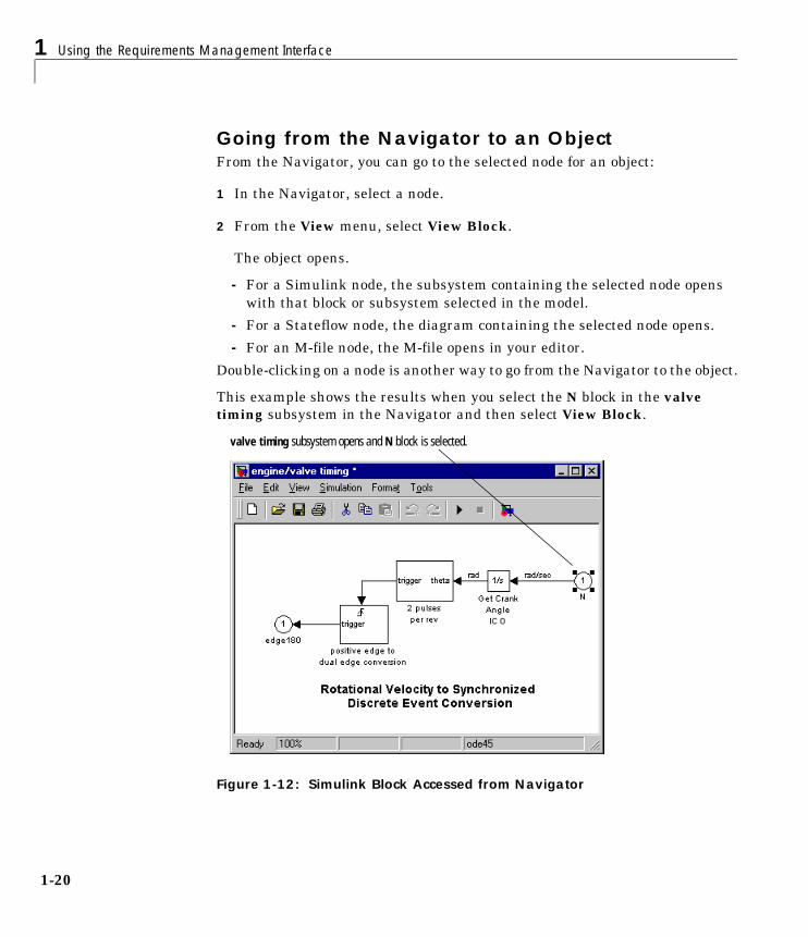
Going from the Navigator to an ObjectFrom the Navigator, you can go to the selected node for an object:
1 In the Navigator, select a node.
2 From the View menu, select View Block.
The object opens.
- For a Simulink node, the subsystem containing the selected node openswith that block or subsystem selected in the model.
- For a Stateflow node, the diagram containing the selected node opens.
- For an M-file node, the M-file opens in your editor.
Double-clicking on a node is another way to go from the Navigator to the object.
This example shows the results when you select the N block in the valvetiming subsystem in the Navigator and then select View Block.
Figure 1-12: Simulink Block Accessed from Navigator
valve timing subsystem opens and N block is selected.

Viewing Requirements in the Navigator
1-21
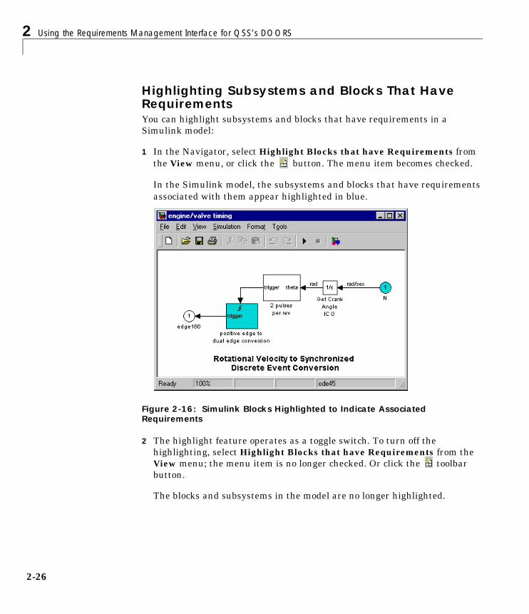
Highlighting Subsystems and Blocks That Have RequirementsYou can highlight subsystems and blocks that have requirements in aSimulink model:
1 In the Navigator, select Highlight Blocks that have Requirements fromthe View menu, or click the button. The menu item becomes checked.
In the Simulink model, the subsystems and blocks that have requirementsassociated with them appear highlighted in blue.
This example shows the nodes in the valve timing subsystem that haveassociated requirements.
Figure 1-13: Simulink Blocks Highlighted to Indicate Associated Requirements
2 The highlight feature operates as a toggle switch. To turn off thehighlighting, select Highlight Blocks that have Requirements from theView menu; the menu item is no longer checked. Or click the toolbarbutton.
The blocks and subsystems in the model are no longer highlighted.
1 Using the Requirements Management Interface
1-22
Note When you save a Simulink model, it is saved with the highlighting. Youcannot later turn off the highlighting without opening the model again in theNavigator. Therefore, unless you want the highlighting to become a“permanent” part of the model file, turn off highlighting using the Navigatorbefore you save a model file in Simulink.

2Using the RequirementsManagement Interface forQSS’s DOORS
Overview of the Process . . . . . . . . . . . . . . 2-2Summary of Steps to Use the Requirements Management
Interface . . . . . . . . . . . . . . . . . . . . 2-3
Startup . . . . . . . . . . . . . . . . . . . . . . 2-5
Opening an Object in the Navigator . . . . . . . . . 2-7Stateflow Charts and MATLAB M-Files in the Navigator . . 2-8
Synchronizing the Navigator with DOORS . . . . . . 2-11What Synchronizing Does and When to Synchronize . . . . 2-11How to Synchronize . . . . . . . . . . . . . . . . . 2-12Checking Synchronization . . . . . . . . . . . . . . . 2-14
Linking an Object to a DOORS Requirement . . . . . 2-16
Viewing Requirements in the Navigator . . . . . . . 2-18Indication of Requirements . . . . . . . . . . . . . . 2-18Changing the View in the Navigator . . . . . . . . . . . 2-23Going from the Navigator to DOORS . . . . . . . . . . 2-24Going from the Navigator to a MATLAB Object . . . . . . 2-25Highlighting Subsystems and Blocks That Have
Requirements . . . . . . . . . . . . . . . . . . 2-26
Going from DOORS to an Object . . . . . . . . . . . 2-28
Running a Script from DOORS . . . . . . . . . . . 2-29
2 Using the Requirements Management Interface for QSS’s DOORS
2-2
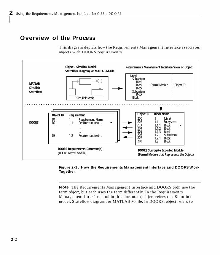
Overview of the ProcessThis diagram depicts how the Requirements Management Interface associatesobjects with DOORS requirements.
Figure 2-1: How the Requirements Management Interface and DOORS Work Together
Note The Requirements Management Interface and DOORS both use theterm object, but each uses the term differently. In the RequirementsManagement Interface, and in this document, object refers to a Simulinkmodel, Stateflow diagram, or MATLAB M-file. In DOORS, object refers to
ModelSubsystem
BlockBlock
SubsystemBlock
Block
BlockFormal Module Object ID
D1 1Object ID
Requirement NameRequirement text .........
1.1
1.2
Requirement
D2
D3
200 1Object ID
ModelSubsystemBlockBlock
SubsystemBlockBlock
Block
1.11.1.11.1.21.1.31.21.2.11.3
Block Name
202203204205206207208
Requirement text ......
Object - Simulink Model,Stateflow Diagram, or MATLAB M-File
MATLABSimulinkStateflow
Requirements Management Interface View of Object
DOORS Requirements Document(s)(DOORS Formal Module)
DOORS Surrogate Exported Module(Formal Module that Represents the Object)
DOORS
Simulink Model

Overview of the Process
2-3
each numbered element in the exported formal module, sometimes called asurrogate module, for a Simulink model, Stateflow diagram, or MATLABM-file. DOORS assigns each of these objects a unique object identifier. In thisdocument, these objects will be referred to as DOORS objects.
Summary of Steps to Use the Requirements Management Interface
Step Description
1 Start the Requirements Management Interface – see “Startup” onpage 2-5.
2 In the Requirements Management Interface Navigator, open anobject (Simulink model, Stateflow diagram, or MATLAB M-file) –see “Opening an Object in the Navigator” on page 2-7.
3 In the Navigator, synchronize the object with DOORS.Synchronizing causes DOORS to create an exported formal modulefor that project. This surrogate exported module provides themapping from DOORS to the Navigator. See “Synchronizing theNavigator with DOORS” on page 2-11.
4 Create links between the surrogate exported module and otherformal modules in DOORS. See “Linking an Object to a DOORSRequirement” on page 2-16.
2 Using the Requirements Management Interface for QSS’s DOORS
2-4
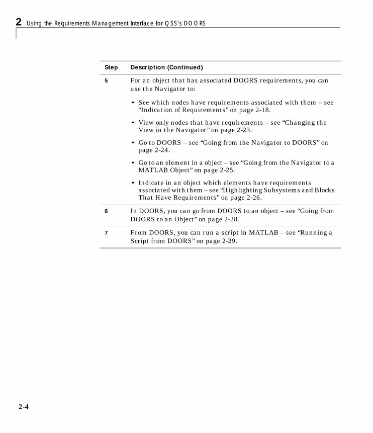
5 For an object that has associated DOORS requirements, you canuse the Navigator to:
• See which nodes have requirements associated with them – see“Indication of Requirements” on page 2-18.
• View only nodes that have requirements – see “Changing theView in the Navigator” on page 2-23.
• Go to DOORS – see “Going from the Navigator to DOORS” onpage 2-24.
• Go to an element in a object – see “Going from the Navigator to aMATLAB Object” on page 2-25.
• Indicate in an object which elements have requirementsassociated with them – see “Highlighting Subsystems and BlocksThat Have Requirements” on page 2-26.
6 In DOORS, you can go from DOORS to an object – see “Going fromDOORS to an Object” on page 2-28.
7 From DOORS, you can run a script in MATLAB – see “Running aScript from DOORS” on page 2-29.
Step Description (Continued)

Startup
2-5
Startup1 Start DOORS and open the project containing the requirements you want to
associate with the object.
You must have a project open in DOORS (be logged in) in order to useMATLAB’s Requirements Management Interface.
2 Start MATLAB with the /automation startup option.
For example, make a shortcut to start MATLAB:
\...\matlab.exe /automation
Note that MATLAB starts up minimized and the directory that MATLABstarts in is <matlabroot>\bin.
3 Edit the file $matlabroot\toolbox\reqmgt\reqmgropts.m to specify theDOORS option for the Requirements Management Interface.
a Type edit reqmgropts at the MATLAB prompt.
The reqmgropts.m file opens in your editor.
b Edit the reqsys line so it appears as follows.
reqsys = 'DOORS';
c Save reqmgropts.m and close it.

2 Using the Requirements Management Interface for QSS’s DOORS
2-6
4 At the MATLAB prompt, type
rminav
or, in Simulink or Stateflow, select Requirements management interfacefrom the Tools menu.
The Navigator window opens.
Figure 2-2: Navigator – No Object Open
Opening an Object in the Navigator
2-7
Opening an Object in the NavigatorYou can use the current model or the file for another object. The object’s filemust be on the MATLAB path or in the current directory. To open an object:
• If the Simulink or Stateflow object you want to associate requirements withis already open and is the currently active model, selectOpen Current Model from the File menu in the Navigator.
• If the Simulink or Stateflow object you want to associate requirements withis not currently open, or if you want to associate requirements with aMATLAB M-file, use Open File:
a Select Open File From the File menu in the Navigator.
The Open Model/File dialog box appears.
b Select the object that you want to associate with requirements and clickOpen.
The object opens in Simulink or Stateflow.
Note While using the Navigator, do not close the model in Simulink. Inaddition, if you close DOORS while using the Navigator, MATLAB closes. Ifthe object has changed, MATLAB prompts you to save your changes.
For a Simulink or Stateflow object, the subsystems, blocks, charts, states, andtransitions appear as nodes in a hierarchical tree structure in the left pane ofthe Navigator. An M-file appears as a single node in the left pane of theNavigator.

2 Using the Requirements Management Interface for QSS’s DOORS
2-8
This example shows the Simulink toolbox\simulink\simdemos\enginemodelin the Navigator.
Figure 2-3: Navigator with engine Model Open
Stateflow Charts and MATLAB M-Files in the Navigator
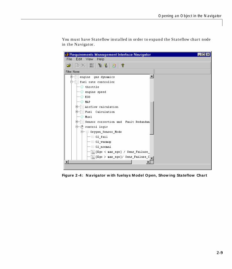
Stateflow Chart in NavigatorThis example shows a partial view of the fuelsys model, which contains thecontrol logic Stateflow chart in the fuel rate controller subsystem.
Opening an Object in the Navigator
2-9
You must have Stateflow installed in order to expand the Stateflow chart nodein the Navigator.
Figure 2-4: Navigator with fuelsys Model Open, Showing Stateflow Chart
2 Using the Requirements Management Interface for QSS’s DOORS
2-10
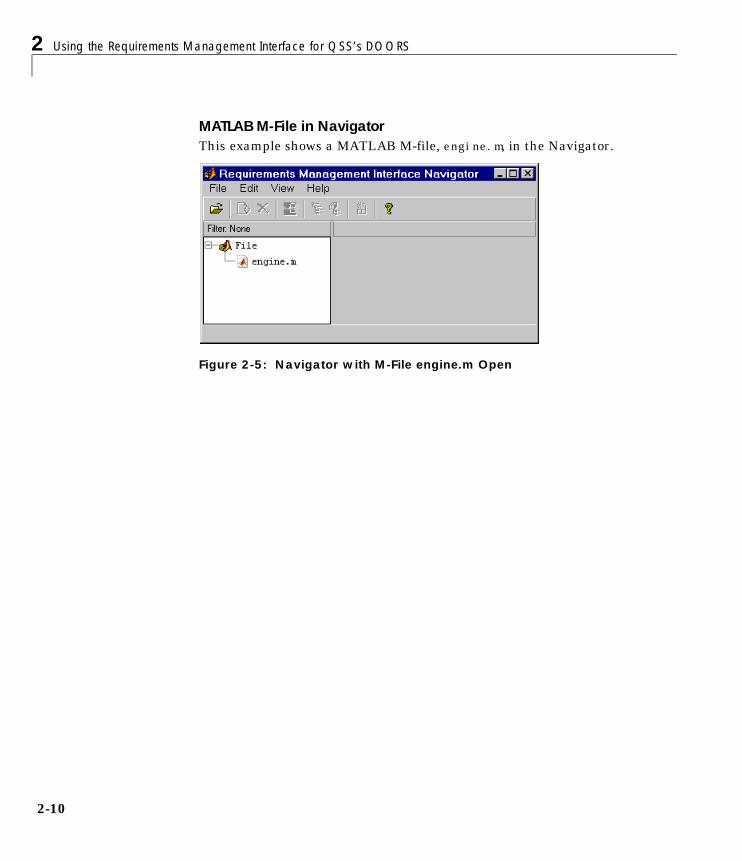
MATLAB M-File in NavigatorThis example shows a MATLAB M-file, engine.m, in the Navigator.
Figure 2-5: Navigator with M-File engine.m Open
Synchronizing the Navigator with DOORS
2-11
Synchronizing the Navigator with DOORS
What Synchronizing Does and When to SynchronizeYou synchronize the object that is open in the Navigator to associate it with aproject in DOORS.
• Synchronize the first time you open a given object in the Navigator. Thiscauses DOORS to create a formal module called a surrogate exported modulethat represents the hierarchical structure of elements in the object. You canthen use DOORS to associate requirements with the elements in thatsurrogate exported module.
• When you open an object in the Navigator that already has a DOORSsurrogate exported module associated with it, the Navigator checks whetherthe object and module are synchronized. If the date of the model or M-file ismore recent than the synchronization date for the DOORS module, you mustsynchronize again.
• Synchronize again whenever you:
- Change links in the DOORS project
- Make changes to the object in Simulink, Stateflow, or MATLAB
Synchronizing causes changes to be reflected in the Navigator for that object,and in the DOORS surrogate exported module for that object.
• Synchronizing automatically saves the object.
- For a Simulink or Stateflow node, the Requirements ManagementInterface stores information about the requirements with the object.
- For an M-file node, the Requirements Management Interface writes acommented line to the M-file. Do not modify this line. For example,
% Autogenerated requirements (do not modify) = { 'DOORS' 'engine' '1' 'true' }
Note You must have write permission for the object in order to synchronize.If you do not have write permission for the object, you can still view theDOORS requirements associated with the object.

2 Using the Requirements Management Interface for QSS’s DOORS
2-12
How to Synchronize
1 From the File menu in the Navigator, select Synchronize. Note that anhourglass does not appear during synchronization; however, you must waitfor a confirmation dialog box to appear.
2 Once the confirmation dialog box appears stating the number of itemssynchronized, click OK to continue.
Synchronizing opens the DOORS surrogate exported module for that object,creating it if one does not already exist. The name of the surrogate exportedmodule is the same as the object name. This example shows the surrogateexported module created for the Simulink engine model.
Figure 2-6: DOORS Surrogate Exported Module for Simulink engine Model
Unique Object Identifier for each subsystem and block in the Simulink model
Hierarchical representation of Simulink model
Describes the block type
Indicates if block was deleted from the Simulink model
Hide the Block Type and Block Deleted columns by selecting Standard View
Menu to go to Simulink model or run a script

Synchronizing the Navigator with DOORS
2-13
Note that:
- Each subsystem and block in the Simulink engine model has a uniqueObject Identifier. For example, the identifier for Air Charge is 3.
- Each DOORS object has a hierarchical number associated with it, (shownin the Block Name column), which represents its relationship to otherobjects in the engine model. For example, 1.1.1 Air Charge, is a block inthe 1.1 Combustion subsystem.
- For each DOORS object, there is a Block Type description.
- If a block has been deleted from a Simulink model or a state has beendeleted from a Stateflow diagram, True appears in the Block Deletedcolumn. Deleted items do not appear in the Navigator.
- You can hide the Block Type and Block Deleted columns by changing theview in the toolbar from DOORS MATLAB Interface to Standard View.
3 You can add a column to the DOORS surrogate exported module thatdisplays the path for each object.
a Select New from the Column menu, or click the button on theDOORS toolbar.
The New Column dialog box appears.
Figure 2-7: New Column Dialog Box in DOORS
b Select Block Name for the Display Attribute.
2 Using the Requirements Management Interface for QSS’s DOORS
2-14
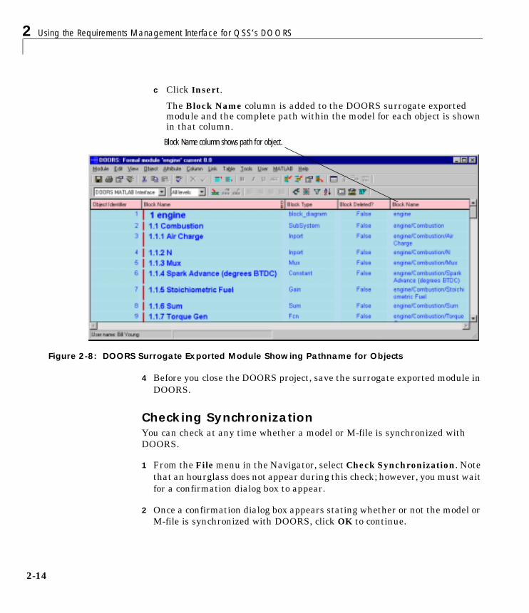
c Click Insert.
The Block Name column is added to the DOORS surrogate exportedmodule and the complete path within the model for each object is shownin that column.
Figure 2-8: DOORS Surrogate Exported Module Showing Pathname for Objects
4 Before you close the DOORS project, save the surrogate exported module inDOORS.
Checking SynchronizationYou can check at any time whether a model or M-file is synchronized withDOORS.
1 From the File menu in the Navigator, select Check Synchronization. Notethat an hourglass does not appear during this check; however, you must waitfor a confirmation dialog box to appear.
2 Once a confirmation dialog box appears stating whether or not the model orM-file is synchronized with DOORS, click OK to continue.
Block Name column shows path for object.

Synchronizing the Navigator with DOORS
2-15
3 If the model or M-file is not synchronized with DOORS and you have writeaccess to the object, from the File menu select Synchronize.
You can view an object and its associated DOORS requirements from theNavigator even if you don’t have write access to the object. First, use CheckSynchronization to make sure you’re viewing a synchronized object.

2 Using the Requirements Management Interface for QSS’s DOORS
2-16
Linking an Object to a DOORS RequirementYou can link a DOORS object in a surrogate exported module to anotherDOORS object in a formal module in order to indicate requirements for theobject. Do this the same way you make links in any DOORS formal module:
1 To add a link from an object in the surrogate exported module to an objectin another formal module, select the object.
That object becomes highlighted.
2 Right-click on the selected object, and from the pop-up menu selectLink>Start link. Or from the Link menu, select Start link.
An outgoing link icon appears with that object in the surrogate exportedmodule.
3 To complete the link, select the object in the formal module you want to linkto. This can be another object in the current surrogate exported module, anobject in another surrogate exported module, or an object in any other formalmodule such as a requirements document.
That object becomes highlighted.
4 Right-click on the selected object, and from the pop-up menu selectLink>Make link from start. Or from the Link menu, select Make link fromstart.
An incoming link icon appears with that object in the exported module.
You can also add links that go in the other direction. A link can start from anobject in a formal module and link to an object in the surrogate exportedmodule.
Note If your Stateflow chart contains transitions that are not unique, do notassociate requirements with them.

Linking an Object to a DOORS Requirement
2-17
The example for the engine model shows two outgoing links: one for the N blockin the valve timing subsystem, and one for the positive edge to dual edgeconversion subsystem.
Figure 2-9: DOORS Surrogate Exported Module with Requirements for engine

2 Using the Requirements Management Interface for QSS’s DOORS
2-18
Viewing Requirements in the NavigatorUse the Navigator to see which objects have requirements associated withthem.
Indication of RequirementsIn the Navigator, you can see which nodes have requirements associated withthem by the shading of the node’s icons.
1 Select Synchronize from the File menu in the Navigator so that the linksyou just made in DOORS are reflected in the Navigator.
This example shows that nodes for the N block in the valve timingsubsystem and the positive edge to dual edge conversion subsystem areshaded, indicating they have DOORS requirements associated with them.

Viewing Requirements in the Navigator
2-19
The nodes in the positive edge to dual edge conversion subsystem arelightly shaded, indicating they belong to a subsystem that has requirementsassociated with it.
Figure 2-10: Navigator Showing Simulink Nodes That Have DOORS Requirements
The shading of a node’s icon indicates whether or not it has associatedrequirements, as shown in the following table.
Shaded block - has requirement
Unshaded block - no requirement
Shaded subsystem - has requirement
Lightly shaded block - belongs to subsystem that has requirement
Unshaded subsystem - no requirement

2 Using the Requirements Management Interface for QSS’s DOORS
2-20
Table 2-1: Node Icons in Navigator and What They Represent
Node Shading What It Represents
Not shaded Simulink subsystem with no requirements
Shaded Simulink subsystem that has requirements
Lightly shaded Simulink subsystem belonging to a subsystem that hasrequirements; subsystem itself has no requirements
Not shaded Simulink block with no requirements
Shaded Simulink block that has requirements
Lightly shaded Simulink block belonging to a subsystem that has requirements;block itself has no requirements
Not shaded Stateflow chart with no requirements
Shaded Stateflow chart that has requirements
Lightly shaded Stateflow chart belonging to a subsystem that has requirements;chart itself has no requirements
Not shaded Stateflow state with no requirements
Shaded (withyellow)
Stateflow state that has requirements
Lightly shaded Stateflow state belonging to a superstate, chart, or subsystem thathas requirements; state itself does has no requirements
Not shaded Stateflow transition with no requirements
Shaded (withblue)
Stateflow transition that has requirements
Lightly shaded Stateflow transition belonging to a superstate, chart, or subsystemthat has requirements; transition itself has no requirements
Not shaded MATLAB M-file with no requirements
Shaded MATLAB M-file that has requirements
Viewing Requirements in the Navigator
2-21
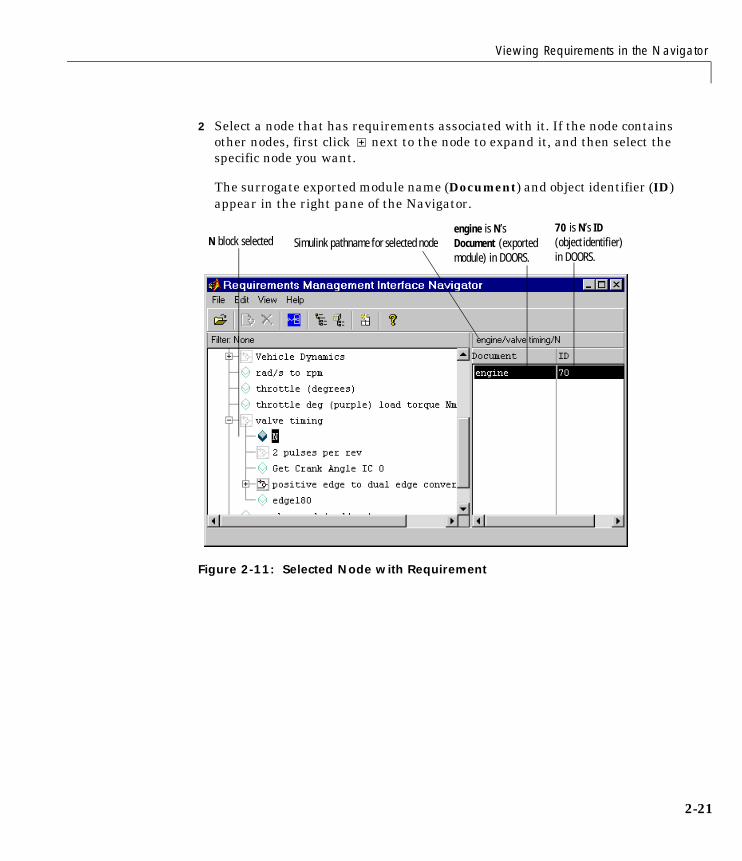
2 Select a node that has requirements associated with it. If the node containsother nodes, first click next to the node to expand it, and then select thespecific node you want.
The surrogate exported module name (Document) and object identifier (ID)appear in the right pane of the Navigator.
Figure 2-11: Selected Node with Requirement
N block selectedengine is N’s Document (exported module) in DOORS.
70 is N’s ID (object identifier) in DOORS.
Simulink pathname for selected node
2 Using the Requirements Management Interface for QSS’s DOORS
2-22
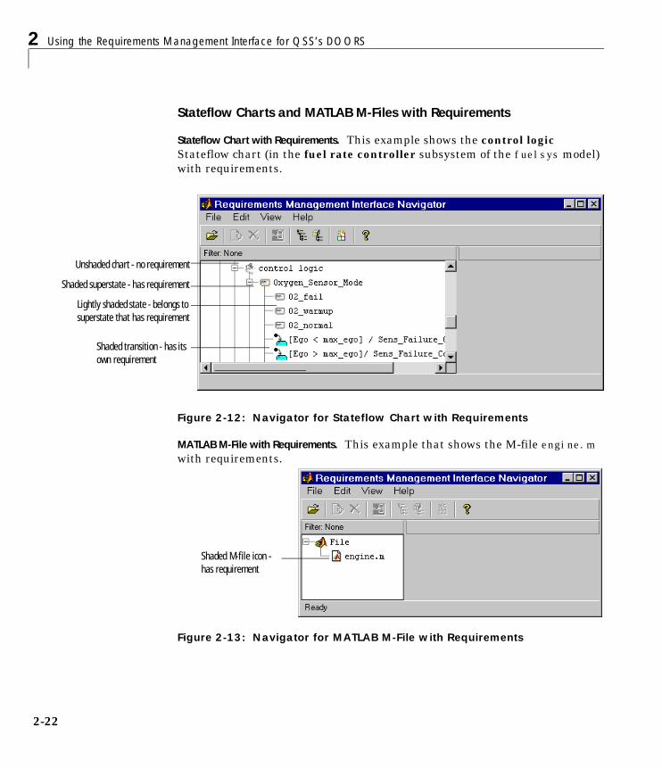
Stateflow Charts and MATLAB M-Files with Requirements
Stateflow Chart with Requirements. This example shows the control logicStateflow chart (in the fuel rate controller subsystem of the fuelsys model)with requirements.
Figure 2-12: Navigator for Stateflow Chart with Requirements
MATLAB M-File with Requirements. This example that shows the M-file engine.mwith requirements.
Figure 2-13: Navigator for MATLAB M-File with Requirements
Unshaded chart - no requirement
Shaded superstate - has requirement
Lightly shaded state - belongs to superstate that has requirement
Shaded transition - has its own requirement
Shaded M-file icon - has requirement
Viewing Requirements in the Navigator
2-23
Changing the View in the NavigatorIn the Navigator, you can change the view to:
• “Make Panes Wider or Narrower”
• “Show or Hide Lower Levels in the Tree”
• “Show Only the Highest Level in the Tree” hiding the lower levels
• “Show Only Nodes That Have Requirements” associated with them
Make Panes Wider or NarrowerDrag the separator bar between the left and right panes in the Navigator tomake one of the panes wider and the other pane narrower.
You can make the overall window larger or smaller by dragging any edge of thewindow.
Show or Hide Lower Levels in the Tree
• Click to expand a node in the tree, which shows lower levels.
• Click to collapse a node in the tree, which hides the lower levels.
Show Only the Highest Level in the TreeFrom the View menu, select Refresh. This collapses the tree so that only thehighest level nodes are shown.
Show Only Nodes That Have RequirementsFrom the View menu, select Show Requirement Nodes or click thebutton.

2 Using the Requirements Management Interface for QSS’s DOORS
2-24
Only nodes that have requirements associated with them are shown. Othernodes are hidden. When a node is highlighted, the full path of the node is shownin the righthand pane. The Filter display indicates Requirements Only.
Figure 2-14: Navigator with Requirements Only Filter
When the Filter is Requirements Only, to see all nodes, select Show AllNodes from the View menu, or click the button. The Filter display thenindicates None, meaning that there is no filter applied to the requirementslisting and all requirements are included.
Going from the Navigator to DOORS
1 In the Navigator, select a node that has an associated requirement.
2 From the View menu, select Navigate to Requirement, or click thenavigate button .
That object becomes highlighted in the DOORS exported module.
Double-clicking in the Document or ID field for the requirement is anotherway to go from the Navigator to DOORS.
Filter indicates that view shows only those nodes with requirements.

Viewing Requirements in the Navigator
2-25
Going from the Navigator to a MATLAB ObjectFrom the Navigator, you can go to the selected node for an object:
1 In the Navigator, click on a node to select it.
2 From the View menu, select View Block.
The object opens.
- For a Simulink node, the subsystem containing the selected node opens inSimulink with that block or subsystem selected in the model.
- For a Stateflow node, the diagram containing the selected node opens inStateflow.
- For an M-file node, the M-file opens in your editor.
Double-clicking on a node is another way to go from the Navigator to the object.
This example shows the results when you select the N block in the valvetiming subsystem in the Navigator and then select View Block.
Figure 2-15: Simulink Block Accessed from Navigator
valve timing subsystem opens and N block is selected.
2 Using the Requirements Management Interface for QSS’s DOORS
2-26
Highlighting Subsystems and Blocks That Have RequirementsYou can highlight subsystems and blocks that have requirements in aSimulink model:
1 In the Navigator, select Highlight Blocks that have Requirements fromthe View menu, or click the button. The menu item becomes checked.
In the Simulink model, the subsystems and blocks that have requirementsassociated with them appear highlighted in blue.
Figure 2-16: Simulink Blocks Highlighted to Indicate Associated Requirements
2 The highlight feature operates as a toggle switch. To turn off thehighlighting, select Highlight Blocks that have Requirements from theView menu; the menu item is no longer checked. Or click the toolbarbutton.
The blocks and subsystems in the model are no longer highlighted.

Viewing Requirements in the Navigator
2-27
Note When you save a Simulink model, it is saved with the highlighting. Youcannot later turn off the highlighting without opening the model again in theNavigator. Therefore, unless you want the highlighting to become a“permanent” part of the model file, turn off highlighting using the Navigatorbefore you save a model file in Simulink.

2 Using the Requirements Management Interface for QSS’s DOORS
2-28
Going from DOORS to an ObjectIn DOORS, you can go from a DOORS object in a surrogate exported module toSimulink, Stateflow, or your M-file editor:
1 In the DOORS exported module, click on an object to select it.
That object becomes highlighted.
2 From the MATLAB menu, choose Select item.
The object opens:
- For a Simulink object, the subsystem containing the selected object opensin Simulink with that block or subsystem selected in the model.
- For a Stateflow object, the diagram containing the selected object opens inStateflow.
- For an M-file object, the M-file opens in your editor.
If the DOORS Block Deleted status for the object is True, you cannotnavigate to the object.
Note Although the MATLAB menu and Select item feature appear in allDOORS formal modules, you can only use them in a surrogate exportedmodule.
Running a Script from DOORS
2-29
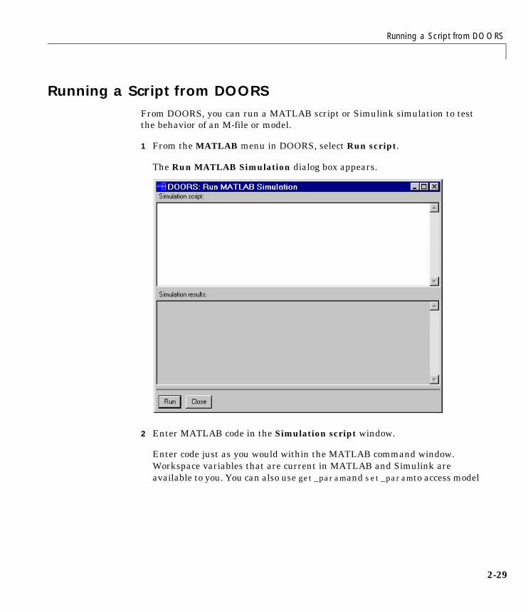
Running a Script from DOORSFrom DOORS, you can run a MATLAB script or Simulink simulation to testthe behavior of an M-file or model.
1 From the MATLAB menu in DOORS, select Run script.
The Run MATLAB Simulation dialog box appears.
2 Enter MATLAB code in the Simulation script window.
Enter code just as you would within the MATLAB command window.Workspace variables that are current in MATLAB and Simulink areavailable to you. You can also use get_param and set_param to access model
2 Using the Requirements Management Interface for QSS’s DOORS
2-30
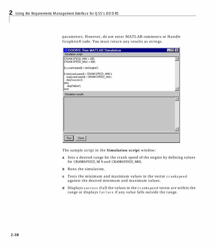
parameters. However, do not enter MATLAB comments or HandleGraphics® code. You must return any results as strings.
The sample script in the Simulation script window:
a Sets a desired range for the crank speed of the engine by defining valuesfor CRANKSPEED_MIN and CRANKSPEED_MAX.
b Runs the simulation.
c Tests the minimum and maximum values in the vector crankspeedagainst the desired minimum and maximum values.
d Displays success if all the values in the crankspeed vector are within therange or displays failure if any value falls outside the range.

Running a Script from DOORS
2-31
3 Click Run.
DOORS sends the script to MATLAB. MATLAB runs the M-file orsimulation and then returns the results as a string to DOORS, whichdisplays the results in the Simulation results window.
MATLAB also returns error messages to the Simulation results window.
4 Vary the script to test other simulations.
In this script you could vary the values of CRANKSPEED_MIN andCRANKSPEED_MAX.
5 Click Close.
DOORS attaches the script to the current DOORS surrogate exportedmodule so it is available the next time you want to run a MATLAB M-file orSimulink simulation from DOORS.

2 Using the Requirements Management Interface for QSS’s DOORS
2-32
3
Reference
There is only one function for the Requirements ManagementInterface, rminav.

rminav
3-2
3rminavPurpose Start the Requirements Management Interface
Graphical Interface
As an alternative to the rminav function, in Simulink or Stateflow, selectRequirements management interface from the Tools menu.
Syntax rminav
Description rminav starts the Requirements Management Interface Navigator window.
If you specified reqsys = 'OTHERS' in the MATLAB file reqmgropts.m, thestandard version of the Navigator window opens. You can associaterequirements documents written in HTML, Microsoft Word, or Microsoft Excelwith Simulink models, Stateflow diagrams, and MATLAB M-files.
If you specified reqsys = 'DOORS' in reqmgropts.m, the DOORS version of theNavigator window opens. You can associate QSS DOORS requirements withSimulink models, Stateflow diagrams, and MATLAB M-files.
To associate DOORS requirements with MATLAB objects, you must startMATLAB with the /automation option.
See the Requirements Management Interface User’s Guide for instructions touse the Navigator window.

I-1
Index
Aautomation startup option 2-5
Bblocks
highlighting to indicate requirements 1-21,2-26
Cclosing DOORS 2-7configuring MATLAB
for DOORS version 2-5for standard version 1-4
Ddeleting requirements 1-17DOORS objects
Block Type descriptions 2-13definition 2-2hierarchical numbers 2-13linking to a requirement 2-16object identifiers 2-13opening the object in MATLAB 2-28
DOORS surrogate exported modules 2-11definition 2-3displaying the path for each object 2-13going to MATLAB from DOORS 2-28naming of 2-12saving 2-14
DOORS/Navigator interactionchecking synchronization 2-14synchronizing objects and DOORS projects
2-11
Eexamples
blocks highlighted for requirements 1-21, 2-26DOORS surrogate exported module 2-12DOORS surrogate exported module with links
to requirements 2-17MATLAB M-file xiiinode with associated requirements 1-12, 2-21Simulink engine model xiSimulink/Stateflow fuelsys model xiii
exported formal modules 2-11
Ffilters for Navigator window 1-19, 2-24
Iinstalling xiv
steps for DOORS users xiv
Llinking DOORS objects to requirements 2-16
MMATLAB M-Files
shading of node icons 1-16, 2-22MATLAB M-files
display in Navigator window 1-8, 2-10example xiii
MATLAB scriptsrunning from DOORS 2-29

Index
I-2
NNavigator window
changing nodes viewed 1-18, 2-23changing pane size 1-18, 2-23
node iconsshading for requirements 1-15, 2-20
Oobjects
associating with DOORS requirements 2-2associating with requirements documents
1-2definition 2-2display as nodes in tree 1-5, 2-7display in Navigator window 1-6, 1-8, 2-8,
2-10going from the Navigator to 1-20, 2-25linking to a DOORS requirement 2-16opening in DOORS version 2-7opening in standard version 1-5synchronizing with DOORS 2-11, 2-12
opening objects 1-5, 2-7overview
features viiiNavigator/DOORS process 2-2Navigator/requirements document process
1-2steps for using DOORS version 2-3steps for using standard version 1-3
Rreqmgropts.m
specifying DOORS option 2-5specifying OTHERS option 1-4
requirements documents in standard versionaccepted documents 1-9going to top of document 1-9opening 1-19specifying a location within document 1-9
requirements in DOORS versiongoing to DOORS object 2-24how they’re saved by Navigator 2-11making links within DOORS 2-16viewing 2-18viewing for a node 2-21
requirements in standard versionadding 1-9changing document or location 1-17deleting 1-17how they’re saved by Navigator 1-12viewing 1-13viewing for a node 1-17
rminav 3-2starting DOORS version 2-6starting standard version 1-4
Ssaved requirements 1-12, 2-11saving Simulink models 1-22, 2-27scripts
running from DOORS 2-29simulations
running from DOORS 2-29
Index
I-3
Simulink modelsblocks highlighted for requirements 1-21, 2-26display in Navigator window 1-6, 2-8engine model xirepresentation in DOORS 2-12saving with highlighting 1-22, 2-27shading of node icons 1-13, 2-18
starting DOORS 2-5starting Requirements Management Interface
DOORS version 2-5standard version 1-4
startup shortcut for DOORS version 2-5Stateflow charts
display in Navigator 1-6, 2-8fuel rate controller chart xiiishading of node icons 1-16, 2-22
Stateflow transitions 1-11, 2-16subsystems
highlighting blocks with requirements 1-21,2-26
synchronizationchecking 2-11, 2-14
synchronizing objects and DOORS projects 2-11system requirements xiv
Ttransitions in Stateflow 1-11, 2-16

Index
I-4