Embed Size (px)
Citation preview


Requirements for Secondary Voltage
Revenue Metering (750 V and less)
January 2021

Copyright and Reprint Provision Copyright © 2021 by BC Hydro.
Reprint Provisions:
a) Copying all, or any part of, this document is permitted provided credit is given
to BC Hydro and provided the copies of this document or parts thereof are not
sold for profit; and
b) This document may be stored in any type of electronic retrieval system
provided BC Hydro is clearly indicated as the source and provided no profit accrues from such storage.

Table of Contents
Contents
Copyright and Reprint Provision ................................................................................................2
Table of Contents .........................................................................................................................3
1. Overview .................................................................................................................................6
2. Disclaimer ...............................................................................................................................6
3. General....................................................................................................................................8
3.1 Approval ...........................................................................................................................8
3.2 Location ............................................................................................................................8
3.2.1 General......................................................................................................................8
3.2.2 Meter Communications ..........................................................................................9
3.3 Access ........................................................................................................................... 14
3.4 Illumination.................................................................................................................... 14
3.5 Existing Installations ................................................................................................... 15
3.6 Drawings ....................................................................................................................... 15
3.7 Underground and Overhead Main Services ........................................................... 16
3.8 Net Metering ................................................................................................................. 16
3.9 Metering Type and Sequence ................................................................................... 16
4. Self-Contained Metering...................................................................................................... 18
4.1 General.......................................................................................................................... 18
4.2 Individual Meter Sockets ............................................................................................ 19
4.2.1 Meter Socket Cover Removal ............................................................................ 19
4.2.2 Mounting Height.................................................................................................... 19
4.2.3 Enclosures for Permanent Meter Sockets (Kiosk) ......................................... 20
4.2.4 Recessed Mounting ............................................................................................. 21
4.2.5 Ground Connections ............................................................................................ 21
4.2.6 Meters Mounted on Poles ................................................................................... 21
4.2.7 Gas Meters and Propane Meters ...................................................................... 22
4.3 Multiple Main Meter Sockets ..................................................................................... 22
4.4 Meter Centres .............................................................................................................. 23
4.4.1 Surplus Meter Positions ...................................................................................... 23
BC Hydro will not allow more than two surpluses in the above circumstances. .... 24
4.4.2 Spare Meter Positions ......................................................................................... 24
4.5 Grouped Sub Service Metering................................................................................. 24
4.6 Service Pedestals........................................................................................................ 26
4.7 Schematic Drawings ................................................................................................... 26
4.7.1 120/240 V, 1 Phase, 3 Wire, Main Service ...................................................... 28
4.7.2 120/240 V, 1 Phase, 3 Wire, Sub Services...................................................... 29
4.7.3 120/208 V, Network, Main Service .................................................................... 30
4.7.4 120/208Y V, 3 Phase, 4 Wire, Main Service ................................................... 31
4.7.5 120/208Y V, 3 Phase, 4 Wire, Sub Services................................................... 32
4.7.6 277/480Y V, 3 Phase, 4 Wire, Main Service ................................................... 33
4.7.7 277/480Y V, 3 Phase, 4 Wire, Sub Services................................................... 34

4.7.8 347/600Y V, 3 Phase, 4 Wire, Main Service ................................................... 35
4.7.9 347/600Y V, 3 Phase, 4 Wire, Sub Services................................................... 36
4.7.10 240 V, 3 Phase, 3 Wire Delta, Main Service ................................................ 37
4.7.11 480 V, 3 Phase, 3 Wire Delta, Main Service ................................................ 38
4.7.12 600 V, 3 Phase, 3 Wire Delta, Main Service ................................................ 38
5. Instrument Transformer Metering ...................................................................................... 39
5.1 General.......................................................................................................................... 39
5.1.1 1 Phase .................................................................................................................. 39
5.1.2 3 Phase .................................................................................................................. 41
5.2 Schematic Drawings ................................................................................................... 42
5.2.1 120/240 V, 1 Phase, 3 Wire Service – Instrument Transformer Enclosure or Compartment.................................................................................................................. 43
5.2.2 120/240 V, 1 Phase, 3 Wire Service – 400 A Meter Socket Assembly with
an Integral CT ..................................................................................................................... 44
5.2.3 120/208Y V, 3 Phase, 4 Wire Service .............................................................. 45
5.2.4 277/480Y V or 347/600Y V, 3 Phase, 4 Wire Service ................................... 46
5.2.5 240 V, 3 Phase, 3 Wire Delta Service .............................................................. 47
5.2.6 480 V or 600 V, 3 Phase, 3 Wire Delta Service .............................................. 48
5.3 Instrument Transformer Enclosure........................................................................... 49
5.3.1 Responsibility ........................................................................................................ 49
5.3.2 Equipment.............................................................................................................. 50
5.4 Switchgear Instrument Transformer Compartment............................................... 53
5.4.1 Responsibility ........................................................................................................ 53
5.4.2 Equipment.............................................................................................................. 54
5.5 120/240 V, 1 Phase, 400 A Meter Socket Assembly with an Integral CT ........ 57
5.5.1 Responsibility ........................................................................................................ 57
5.5.2 Equipment.............................................................................................................. 58
5.6 Instrument Transformers............................................................................................ 59
5.6.1 Metered fire pump service Loads >67h.p. (50kW) .......................................... 60
5.7 Transformer-Type Meter Socket............................................................................... 60
5.7.1 Indoor/Outdoor Installations ............................................................................... 60
5.7.2 Grounding .............................................................................................................. 62
5.7.3 Optional Meter Compartment ............................................................................. 62
5.8 Conduit .......................................................................................................................... 63
6. Reference Drawings ............................................................................................................. 65
6.1 Underground Main Service Meter Sockets ............................................................. 65
6.2 Sealing Ring ................................................................................................................. 67
6.3 Individual Pole Mounted Meter Socket .................................................................... 68
6.4 Individual Wall Mounted Meter Socket Near a Gas or Propane Meter ............. 69
6.5 Multiple Main Meter Socket ....................................................................................... 70
6.6 Meter Centre................................................................................................................. 71
6.7 Grouped Sub Service Metering ................................................................................. 72
6.8 Service Pedestal.......................................................................................................... 73
6.9 120/240 V, 1 Phase, Instrument Transformer Enclosure ..................................... 74
6.10 3 Phase Instrument Transformer Enclosure ....................................................... 75

6.11 120/240 V, 1 Phase, Metering with a Single 3 Wire Bar Type CT .................. 77
6.12 120/240 V, 1 Phase, Metering with Two 2 Wire Bar Type CTs........................ 78
6.13 3 Phase, 4 Wire, Metering with Bar Type CTs .................................................... 79
6.14 Typical Indoor Window CT ..................................................................................... 80
6.15 Typical Indoor/Outdoor Donut CT ......................................................................... 81
6.16 General Arrangement of Meter Inside Electrical/Meter Room ......................... 82
6.17 Meter Connection to RF Mesh Network ............................................................... 83
6.18 Multiple Meter Rooms Conduit Arrangement...................................................... 84
6.19 Multiple Meter Rooms on Multiple Levels Conduit Arrangement.................... 85
7 Definitions......................................................................................................................... 86

6 January 2021 - Requirements for Secondary Voltage Revenue Metering (Rev. 2)
1. Overview
This document contains BC Hydro’s requirements for revenue metering installations
operating at 750 V and less. These requirements also apply to revenue metering installations in the City of New Westminster, if any.
If needed, any BC Hydro related information and/or Standards referred to in this Requirement should be inquired upon from local BC Hydro Design.
Comments are written in italics.
New additions and changes from previous version are denoted with a vertical line
preceding the sentence.
2. Disclaimer
This document is not intended as a design specification or as an instruction manual
for the Customer and this document shall not be used by the Customer for those purposes. Persons using information included in this document do so at no risk to
BC Hydro, and they rely solely upon themselves to ensure that their use of all or any
part of this document is appropriate in the particular circumstances.
The Customer, its employees or agents must recognize that they are, at all times,
solely responsible for the plant design, construction and operation. Neither
BC Hydro nor any of their employees or agents shall be nor become the agents of the Customer in any manner howsoever arising.
BC Hydro’s review of the specifications and detailed plans shall not be construed as confirming or endorsing the design or as warranting the safety, durability or reliability
of the Customer’s facilities. BC Hydro, by reason of such review or lack of review,
shall be responsible for neither the strength, adequacy of design or capacity of equipment built pursuant to such specifications, nor shall BC Hydro, or any of their
employees or agents, be responsible for any injury to the public or workers resulting
from the failure of the Customer facilities.
In general, the advice by BC Hydro, any of its employees or agents, that the
Customer’s plant design or equipment meets certain limited requirements of
BC Hydro does not mean, expressly or by implication, that all or any of the requirements of the law or other good engineering practices have been met by the
Customer in its plant, and such judgement shall not be construed by the Customer or
others as an endorsement of the design or as a warranty, by BC Hydro, or any of its employees.

7 January 2021 - Requirements for Secondary Voltage Revenue Metering (Rev. 2)
The information contained in this document is subject to change and may be revised at any time. Any user of this document is advised to confirm the current
version and consult with BC Hydro on the applicability of its provisions. Without
limiting BC Hydro may refuse service, and energization of the metering installation, if in its view the Customer’s facilities, including the service entrance and metering
equipment, are unsafe, hazardous, or otherwise does not comply with the
Requirements set out in this document.

8 January 2021 - Requirements for Secondary Voltage Revenue Metering (Rev. 2)
3. General 3.1 Approval
a) The proposed metering equipment locations and voltage shall be approved
by BC Hydro prior to installation. If the design is subsequently changed, re-
approval is required prior to energization.
b) The metering equipment shall be certified and installed in accordance with
the latest edition of the Canadian Electrical Code. If special permission for
a deviation from the Canadian Electrical Code, that impacts metering, is
requested from the provincial or municipal inspection authority, special written approval shall first be obtained from BC Hydro.
3.2 Location
3.2.1 General
1. Shall be installed in a clean readily accessible location free from
severe or continual vibration;
For rural applications, meter location shall be readily accessible by vehicles at all times;
2. Shall not be installed in locations which may be hazardous to persons
installing, testing, reading or maintaining the equipment; 3. Shall be protected from damage due to vandalism, vehicles etc.; 4. Shall not be installed in garages or carports;
5. Shall not be installed in a location which requires ladder or manhole access;
6. Grouped Sub Service Metering and multiple meters shall be installed
inside a designated electrical/meter room, and at least one meter socket shall be mounted as per section 6.16.
7. Exterior meter(s), not mounted inside a metal enclosure, no conduit
arrangement is required for the purpose of meter communication; 8. Meter(s) inside wood frame construction above grade, no conduit
arrangement is required for the purpose of meter communication;
9. Per CEC, part I and local Building Codes, termination boxes shall be suitable for the environment in which they are placed.
10. There has to be minimum 0.3 m separation distance between the
meter base and closest obstruction/equipment. 11. Each termination/pull box located inside the building shall be securely
fastened to the wall with sufficient room for an additional termination
box.
12. A minimum of 1 m working space by 2.2 m headroom shall be provided and maintained in front of all metering equipment, and to the
sides and back, where access is required.

9 January 2021 - Requirements for Secondary Voltage Revenue Metering (Rev. 2)
13. If an existing metering location going through a service upgrade and/or meter alteration does not meet the above criteria, the Customer shall
relocate the metering equipment to a location that meets the above
criteria. 14. Single phase detached single family residential metering equipment
shall not be located indoors except in the case of power shed or
service closet as approved in advance by BC Hydro. 15. Buildings requiring conduit(s) and termination box(es) for Meter
Communications shall be defined as per Section 3.2.2.
See section 5.1.1.1 and section 5.1.1.2 for 1 phase services over 200 A and section
5.1.2.1 for a possible exception for 3 phase services over 200 A.
3.2.2 Meter Communications
BC Hydro revenue meters must be able to transmit data to and from the BC Hydro
IT network. The data is transmitted by radio frequency (similar to cell phones).
Radio frequency waves cannot transmit through concrete, metal, or earth; therefore some buildings will require electrical conduit(s) and termination box(es)
to enable meter communication through wires.
Soft copy, dimensioned PDF drawing(s) shall be provided by the customer to BC
Hydro prior to construction showing conduit configurations, and physical
locations of terminations and pull boxes. BC Hydro conduits for the use of BC Hydro Meter Communications shall be clearly labelled on the drawing(s).
A. Conduit and Termination Box Applications for Meter Communications:
• Meter(s) below grade (parkade) require conduit(s) and termination
box(es);
• Concrete and/or metal clad buildings require conduit(s) and termination box(es);
• Mixed wood/concrete and any other structure not covered above, requires
consultation with BC Hydro Design prior to any design work;
B. Conduit and Termination Box Requirements:
1. For structures having less than 4 floors:
a) Buildings having a single meter room at or below grade (parkade);

10 January 2021 - Requirements for Secondary Voltage Revenue Metering (Rev. 2)
the conduits and termination boxes shall be run from the meter
room to an exterior wall as per section 6.17.
b) For a building with an underground parkade, the exterior
termination box shall be mounted under the parkade entrance
overhang:
i. within two metres of the parkade entrance opening; and
ii. outside of the parkade entrance gate; and
iii. a minimum of two metres from any planned parkade
entrance gate controller or sensor. c) If the building contains more than one meter room at or below grade
(parkade), conduits and termination boxes shall be run to connect
each at or below grade meter room in a star configuration to a
single meter room. This single meter room shall also include the
conduit and termination box to the exterior of the building as per
section 6.17.
2. For concrete structures having 4 or more floors:
a) In addition to the requirements in above section, an additional
conduit and termination box shall be run from the top-most meter
room/closet to an external face of a rooftop mechanical room or
equivalent as per section 6.17; and
b) Where no rooftop mechanical room exists above the roof line, each
meter room/closet shall be interconnected with the main meter
room via conduit similar to what is shown in section 6.18.
3. Concrete buildings having a single meter room at or below grade (parkade) or wood frame buildings having a single meter room below grade (parkade);
the conduit and termination boxes shall be run from the meter room to an
exterior wall as per section 6.17. The determination of which exterior wall the conduit and termination box are mounted on shall be as follows;
For a building with an underground parkade, under the parkade entrance
overhang as per installation requirements below.
• within two metres of the parkade entrance opening; and
• outside of the parkade entrance gate; and
• a minimum of two metres from any planned parkade entrance gate controller or sensor.

11 January 2021 - Requirements for Secondary Voltage Revenue Metering (Rev. 2)
For a building with no underground parkade, on the exterior wall which has
line of sight to the neighbouring buildings across the street or alley. If no
neighbour across the street or alley, then it is up to the customer's
preference whether to face the street or alley.
4. If the building contains more than one meter room on the same level, or
below grade (parkade), conduits and termination boxes shall be run to connect each meter room in a star or daisy chain configuration to the
main meter room as per section 6.18. The main meter room shall also
include the conduit and termination box to the exterior of the building as per section 6.17.
5. The main meter room would be the meter room closest to ground level
containing one or more transformer-type meters and/or house meter.
6. In addition to the requirements above, Indoor Meter Closets on multiple
levels shall be interconnected via a daisy chain of conduits run vertically
from one Indoor Meter Closet on one level to one Indoor Meter Closet on
the next level with the conduit terminating in each Indoor Meter Closet as per section 6.19.
o If any floor above grade has more than one Indoor Meter Closet
on that floor, conduit shall be run horizontally from the additional Indoor Meter Closet(s) to the Indoor Meter Closet containing the vertical daisy chained conduits as per section 6.19.
o Conduits are not required beyond the 7th floor Indoor Meter Closet(s) unless there is a vertical gap of 4 or more floors in between the Indoor Meter Closets. If there is no Indoor Meter Closet on and beyond the 7th floor the conduits shall be run to the 6th floor Indoor Meter Closet(s).
o If there is a vertical gap of 4 or more floors in between Indoor Meter
Closets, provide conduit to bridge the gap between these Indoor Meter Closets i.e. provide conduit from the topmost Indoor Meter
Closet in the lower floor, to the bottommost Indoor Meter Closet in
the next-higher floor. Provide conduit in this manner for every gap of 4 or more floors.
7. Conduits entering each Indoor Meter Closet and meter room shall be
terminated in a termination box and multiple conduits into the room or
closet can be terminated in the same box (maximum 4 conduits per box) as per section 6.17.

12 January 2021 - Requirements for Secondary Voltage Revenue Metering (Rev. 2)
C. Conduit and Termination Box Specifications:
1. All material requirements for installation of conduits and termination
boxes are the responsibility of the customer. Each termination box and
conduit shall be permanently marked/labelled for exclusive use of BC
Hydro Meter Communications.
2. All material and connections from termination box to the meter is the
responsibility of BCH per section 6.17.
3. Conduit(s) shall be metallic or rigid PVC, with an inside diameter not less
than 35.00 mm (or 1¼ inch trade size) installed per CEC and local
Building Code. If the conduits(s) will be run within a concrete slab, it may
be non-metallic Coreline (ENT) or rigid PVC.
4. The conduit from the meter room shall be run from a location within 0.3 -
2 m of the Transformer-Type Meter Socket used as house meter. If no
such meter socket is present in the meter room, the conduit shall be run
from a location within 0.3 - 2 m of another meter socket present at that
location in the following order of preference:
i. Any Transformer-Type Meter Socket
ii. Meter Socket used as house meter iii. Any Meter Socket
The above meter socket shall be mounted on a 19 mm (¾”) plywood
backing as per section 6.17.
The plywood backing shall be securely fastened to the wall. Shooting, or
otherwise mounting this meter socket, directly to the wall is not permitted.
5. The conduit termination on the exterior of the building shall be no less
than 2.75 m or more than 4 m above finished grade unless mounted
under the parkade entrance overhang, with a minimum amount of bends.
The maximum degree of bends between termination/pull boxes shall not
exceed 270°, and if the maximum length between termination boxes
exceeds 100 m, an additional pullbox is required. Each end of the conduit
shall terminate in a 150x150x150 mm (minimum) metallic or PVC

13 January 2021 - Requirements for Secondary Voltage Revenue Metering (Rev. 2)
enclosure with a cover for future use by BC Hydro to install signaling
cables. All metallic enclosures shall be bonded and all PVC enclosures
shall come with bonding conductor (with min #10 Cu). A maximum of 4
conduits can terminate in one termination box. Each conduit shall come
with a permanent label attached to both ends of the conduit. Both labels
will be marked with the same unique identifier to distinguish that conduit
from all others.
6. Each conduit shall be equipped with a continuous length of poly pull
string and every termination/pull box shall be identified as for use by “BC
Hydro Meter Communications”. The pull string shall be minimum #8,
polypropylene, and installed in each conduit.
14 January 2021 - Requirements for Secondary Voltage Revenue Metering (Rev. 2)
3.3 Access
a) BC Hydro shall have reasonable access to the metering equipment to permit its reading, testing and maintenance.
b) Where the meter socket is not accessible due to locked doors or alarm
systems, keys shall be provided to BC Hydro.
c) Where it is proposed to locate metering equipment indoors, or within other
secure areas, the accessibility arrangements, systems, equipment etc. shall
be agreed upon by BC Hydro prior to approval of the proposed location.
Equipment and systems may include keys, lock boxes, key fobs, smart cards etc.
d) Electrical rooms on ground floor or parkade level containing metering
equipment shall be accessible by a vertically hinged, lockable door leading
directly to the exterior or the parkade level of the building (roll-up or overhead
garage doors are not acceptable as access doors);
e) Where building does not come with parkade, meter(s) shall be located in
the main electrical room where the supply service is terminated. The main
electrical room shall be at ground level and come with a door leading directly to the exterior of the building as per 6.16.
f) Indoor Meter Closet(s) are only allowed in Multiple Unit Residential
Buildings (MURBs) and Commercial Retail Units (CRUs) where building comes with a main electrical room. The house meter or meters shall be located inside this electrical room per d) and e) above.
g) Where a Premises come with multiple buildings with main and sub-electrical rooms, meters are allowed to be installed in each of the electrical rooms.
3.4 Illumination
When metering equipment are installed indoors, i.e. meter room, power shed, service
closet, Indoor Meter Closet, etc., lighting fixture(s) shall be installed:
a) in the same space containing the metering equipment and shall be controlled by
a wall switch at the room entrance; and

15 January 2021 - Requirements for Secondary Voltage Revenue Metering (Rev. 2)
b) with a minimum illumination of: • 100 to 200 lux horizontal at 750 mm above grade; and
• 100 lux vertical at the front face of the meter.
Hallway lighting, motion sensor controlled light, and pull chains on light is not
acceptable.
3.5 Existing Installations
a) Any existing installations undergoing service upgrade or meter related work as
a result of an alteration shall comply with the latest version of this requirement
and Measurement Canada Bulletin E-24-E. b) Alterations shall not be made to existing metering installations without the prior
written approval of BC Hydro.
c) Load increases shall be per BC Hydro Electric Tariff section 7.1. Any load
increases greater than what is allowed shall not be made without prior written approval of BC Hydro.
This is to ensure the supply service and metering equipment has adequate
capacity for the new load.
d) Any civil work and/or electrical changes affecting metering and billing, e.g.
one meter per unit, on a Premises shall not take place without BC Hydro’s approval. Any alteration work is the responsibility of the customer.
e) Procedures are available from BC Hydro for the temporary and emergency
disconnection of Self-Contained meters. This may only be carried out by qualified electrical contractors to permit alterations or repairs. Approval
from BC Hydro shall be obtained in advance on an individual job-by-job
basis. 3.6 Drawings
When drawings, specifications and site plans are submitted to BC Hydro, details of
the proposed metering equipment and locations shall be included.
Electrical room layout drawings, specifications and site plans shall be submitted to
BC Hydro for approval. The electrical room layout drawing shall include the location, dimension, plan and front elevation for the following equipment:
• Main service box, wireway, pullbox, and sub-service disconnect devices
• Meter sockets and/or Transformer-Type Meter Sockets
• Instrument transformer enclosures and/or switchgear instrument transformer
compartment, including CT and VT locations

16 January 2021 - Requirements for Secondary Voltage Revenue Metering (Rev. 2)
• Meter centres
• Conduit(s) and termination box(es) for meter communication
3.7 Underground and Overhead Main Services
Underground main service meter sockets shall be in accordance with section 6.1.
Contact BC Hydro and refer to the ES53 Series Underground Electrical standards and the ES54 Underground Civil standards for underground main service conduit,
wireway and pull box requirements.
Overhead service meter socket dimensions are not specified since BC Hydro does
not install or terminate the service conductors at the meter socket.
3.8 Net Metering
For net metering tariff applications, refer to the BC Hydro requirements published under
Generating Your Own Electricity at:
https://w ww.bchydro.com/work-with-us/selling-clean-energy/net-m etering.html.
3.9 Metering Type and Sequence
a) Self-Contained Metering, in accordance with section 4 and the following
table, is required for all loads of 200 A or less. Except that, Instrument
Transformer Metering is required for 480V and 600 V, 3 Phase, 3 Wire, Delta services of 200 A or less.
b) Instrument Transformer Metering, in accordance with section 5 and the
following table, is required for:
• All loads over 200 A; • Any 600 V and 480V, 3 Phase, 3 Wire, Delta services.

17 January 2021 - Requirements for Secondary Voltage Revenue Metering (Rev. 2)
Metering Type and Location Summary Table
Current Metering
Type
Voltage Service Fault
Current
Metering Location
See Note 1
Neutral See
Note 2
200 A or
less
Self-
Contained
300 V or
less
Main 10,000 A or less
Line
(Hot)
Isolated
Over 10,000 A
Load (Cold)
Isolated
Sub Any Level
Load (Cold)
Isolated
277/480Y V 3 Phase 4 Wire
Main or Sub
Any Level
Load (Cold)
Isolated
347/600Y V 3 Phase
4 Wire
Main or
Sub
Any
Level
Load
(Cold)
Isolated
Instrument Transformer
480 V 3 Phase 3 Wire Delta
Main or Sub
Any Level
Load (Cold)
NA
Instrument Transformer
600 V 3 Phase 3 Wire Delta
Main or Sub
Any Level
Load (Cold)
NA
Over 200 A
Instrument Transformer
See Schematic Drawings, section 4.7 and 5.2.
1. The metering location is relative to the main service box or sub service
disconnect device. Line side metering is referred to as “hot” metering. Load side metering is referred to as “cold” metering.
2. In accordance with Canadian Electrical Code the neutral shall be isolated from
the meter socket.
3. Where a 3 phase, 4 wire power system supply, serves a 3 phase, 3 wire load,
the neutral shall be part of the metering circuit and shall be extended to the
point-of-metering (POM).
4. Where the metering installation is cold style, the line side disconnect shall be
located adjacent to the meter base. Adjacent means side-by-side in the same
physical location.

18 January 2021 - Requirements for Secondary Voltage Revenue Metering (Rev. 2)
4. Self-Contained Metering
Self-Contained Metering is required for all loads of 200 A or less. Except that,
instrument transformer type metering is required for 480V and 600 V, 3 Phase, 3
Wire, Delta services of 200 A or less. 4.1 General
a) The Customer shall supply the meter socket and sealing ring. They shall be
certified in accordance with CSA Standard C22.2 No. 115, Meter Mounting
Devices and they shall be approved by BC Hydro.
b) The sealing ring shall be a screw type in accordance with section 6.2.
Ringless meter sockets are not permitted.
c) The neutral terminal on 5 jaw meter sockets shall be in the 9 o’clock position.
Prior to 2005 the neutral terminal on some 5 jaw meter sockets was required to be in the 6 o’clock position. When adding a new 5 jaw sub service meter socket to an
existing installation, the new meter socket neutral terminal shall be in the 9 o’clock
position, even if the existing neutral terminals are in the 6 o’clock position.
d) The meter tilt shall not exceed 3° from vertical.
e) Metered and unmetered conductors shall not be installed in the same
raceway, pull box or distribution gutter box.
f) The supply service conductor conduit shall be continuous and without access fittings or junction boxes on the line side of a meter socket, except where a
sealable LB fitting is used beside the Meter Socket;
g) Line and load side conductors shall not be crossed in the meter socket.
h) Where a 3 phase, 4 wire supply, serves a 3 phase, 3 wire load, a 7 jaw, 3 phase, 4 wire meter socket shall be installed and the neutral shall be extended
to the meter socket.
The neutral conductor:
• Shall be white and insulated; and
• Shall carry the same ampacity of the line conductor; and
• Shall not be smaller than No. 6 AWG and meet the minimum conductor

19 January 2021 - Requirements for Secondary Voltage Revenue Metering (Rev. 2)
size rating of the meter socket neutral terminal;
i) Any “collar-type” devices, including surge arrestors, generator transfer and/or
hook ups, transfer switches, etc. shall not be installed within the meter socket
or between the meter socket and the BC Hydro meter.
j) Power quality and load management devices including power factor
correction capacitors, surge protective devices, etc. shall not be installed
on the line side of the BC Hydro billing meters.
k) Prior to the installation of the meter, the Customer shall provide a durable
temporary weather resistant cover over the meter socket opening.
l) When the service is to be temporarily energized prior to the installation of
the meter, CSA approved jumper bars shall be installed in the meter
socket. Proper electrical and mechanical contact must be maintained between the meter socket jaws and the meter terminal blades after the
removal of the jumpers.
m) Underground service meter sockets shall be in accordance with section 6.1. Overhead service meter socket dimensions are not specified since BC Hydro
does not install the conductors.
4.2 Individual Meter Sockets
4.2.1 Meter Socket Cover Removal
Removal of the meter socket cover shall not be possible unless the following
sequence is followed:
• Removal of the sealing ring;
• Removal of the meter; • Operation of the meter socket cover latch;
• Removal of the meter socket cover.
Configurations that rely on seals, in addition to the BC Hydro sealing ring seal, or
padlocks to prevent removal of the meter socket cover are not permitted.
4.2.2 Mounting Height
a) The meter’s centre line shall be 1500 mm to 1800 mm above finished grade in
accordance with section 6.3 and 6.4.

20 January 2021 - Requirements for Secondary Voltage Revenue Metering (Rev. 2)
Municipal kiosks, Meter Centres, Grouped Sub Service Metering, Service
Pedestals mounting heights are per section 4.2.3, 6.6, 6.7 and 4.6
respectively.
b) If the Customer intends to build up the grade after the meter has been
installed, a platform or ramp shall be provided during the interim period. The platform shall not be less than 900 mm by 900 mm.
4.2.3 Enclosures for Permanent Meter Sockets (Kiosk)
a) Permanent meter sockets shall not be installed within a steel or aluminum
enclosure. By special written approval from BC Hydro, the meter socket
may be installed within an steel or aluminum enclosure provided if:
• Special written approval is obtained from BC Hydro; and
• The enclosure has a hinged door; and,
• The enclosure and door do not interfere with the installation, reading or removal of the meter; and
• The enclosure and door do not interfere with the installation or
removal of the meter socket cover; and, • The clearance of 254-305 mm (10-12 inch) is provided between the
inside of the closed enclosure door and the meter socket cover; and,
• The enclosure has a 152-178 mm (6-7 inch) round or square
Lexan or equivalent Polycarbonate viewing window installed on the enclosure door directly in-line with the front of the meter; and,
• The enclosure shall have a 16 mm (5/8 inch) hole which is,
o complete with tamperproof and weatherproof knockout plug on the enclosure roof; and,
o located as close as possible to the front of the enclosure and within 24 inch radius of the meter; and,
o at least 6 inch away from all edges;
b) If it is proposed to lock the enclosure, the details of the locking should include
double padlocking provision as approved by local BC Hydro design.
c) Municipal kiosk meter’s centre line is allowed to be 915 mm to 1800 mm
above finished grade.
Approval for the installation of permanent meter socket within enclosure is typically
only given where the meter may be subject to vandalism and accidental damage where it reasonably cannot be alleviated.

21 January 2021 - Requirements for Secondary Voltage Revenue Metering (Rev. 2)
Temporary construction power meter sockets may be installed within enclosures.
4.2.4 Recessed Mounting
Meter sockets may be recessed within exterior walls provided:
• The associated underground supply service conductors are permitted to be
installed within the exterior wall per BC Hydro Distribution Standards drawings;
o The recess depth is less than the depth of the meter socket, i.e. the
meter socket cover shall project a minimum of 25 mm beyond the finished exterior wall surface; or
o A minimum of 25 mm wide by 25 mm depth spacing shall be
provided between the finished exterior wall surface and on two sides and bottom side of the meter socket;
• Recessing does not interfere with the installation, reading or removal of the
meter; and
• Recessing does not interfere with the installation or removal of the meter socket cover.
The overhead service mast and conductors are consumer service conductors.
Section 6-208 of the Canadian Electrical Code restricts the installation of consumer service conductors within an exterior wall. The meter shall be installed on the
outside of the finished exterior wall for detached single family residential services.
4.2.5 Ground Connections
Where permitted by the Canadian Electrical Code, grounding and its connections for
other systems, such as telephone, cable TV, or etc., shall:
• Not terminate within the meter socket; and • Not terminate or routed through BC Hydro’s wireway/pullbox; and • Not interfere with the installation, reading or removal of the meter; and
• Not interfere with the installation or removal of the meter socket cover.
4.2.6 Meters Mounted on Poles
Meter sockets shall be located on the side of the pole that is not subject to vehicle
damage. If this is not practicable, protection posts shall be installed 600 mm in front of the meter socket in accordance with section 6.3

22 January 2021 - Requirements for Secondary Voltage Revenue Metering (Rev. 2)
4.2.7 Gas Meters and Propane Meters
Meter sockets shall not be installed within 1000 mm of gas meters or within 3000 mm of propane meters, regulators, tanks, or relief devices. See section 6.4.
4.3 Multiple Main Meter Sockets
When, in accordance with section 6-104 of the Canadian Electrical Code multiple meter sockets connected to one supply service are installed on the exterior of a
building; BC Hydro only permits a maximum of FOUR, 1 phase meter sockets. The
multiple main meter sockets:
a) Shall be part of a certified manufactured assembly; and
Site fabricated assemblies are not permitted.
b) Shall be installed in accordance with section 6.5; and
c) Shall meet the requirements of individual meter sockets in section 4.2; and
d) Shall not have spare meter sockets except the spare meter socket is assigned
to a unit that is in construction and to be completed within 6 – 12 months; A clear polycarbonate cover plate (e.g. Lexan) with tabs that plugs into meter
socket jaws and a meter sealing ring shall be supplied and installed; and
e) If they have a separate supply service compartment, removal of the supply
service compartment cover, shall require operation of a latch that can only
be accessed by the removal of the adjacent meter.
Assemblies that require the installation of a padlock or non-meter ring seal to secure
the supply service compartment cover are not permitted.
f) Prior to the installation of the meters by BC Hydro:
• Each Customer suite address or suite number shall be permanently and
legibly marked on the interior of each meter socket and the exterior of each
meter socket cover; and
• All suite doors, complete with their permanent address or suite numbers, shall be installed.
Multiple main meter sockets are “hot style” and are located on the line side of their respective main service boxes. “Hot style” metering may only be used where the
fault current is less than 10,000 A. Where fault current levels are over 10,000 A; use
“cold style” metering.

23 January 2021 - Requirements for Secondary Voltage Revenue Metering (Rev. 2)
4.4 Meter Centres
a) Meter centres shall be installed in accordance with section 6.6; and
b) Meter centres shall be certified in accordance with CSA Standard C22.2 No. 229 Switching and Metering Centres and shall be approved by BC Hydro; and
c) Meter centres shall be cold style with the meter socket located on the load
side of the associated circuit breaker; and
d) The circuit breaker shall have provision for locking in the open position; and
e) The centre-to-centre dimension of adjacent meter sockets shall not be less
than 220 mm and the centre to any adjacent equipment, structure or obstruction shall be not less than 220 mm and;
f) Prior to the installation of the meters by BC Hydro:
• Each Customer suite address or suite number shall be permanently and
legibly marked on the interior of each meter socket and the exterior of each
meter socket cover; and • All suite doors, complete with their permanent address or suite numbers,
shall be installed.
g) Meter centres may be located behind a hallway door provided the door frame
does not restrict the required 1 m clearance, or access to any of the meter
sockets. The following clearance shall be provided between the closed door
and each meter socket cover:
• 250 mm for all meter types.
4.4.1 Surplus Meter Positions
The meter position(s) may or may not require multiple meter centre(s)/stack(s)
inside meter room(s). For a given project involving multiple meter stacks, the
number of meter position(s) that exceed the required number of meter position(s) are defined as surplus meter position(s); for example – a building has a total of 22 units,
therefore, requiring 22 meter positions, but is supplied with 24 meter positions
because meter stacks come in fixed numbers of 3 or 6). Contractors installing meter centre(s)/stack(s) must remove/disable the surplus meter positions with the following
option:
• Remove surplus socket components and install manufacturer supplied metal

24 January 2021 - Requirements for Secondary Voltage Revenue Metering (Rev. 2)
blanking plate to cover socket opening and breaker section.
BC Hydro will not allow more than two surpluses in the above circumstances.
4.4.2 Spare Meter Positions
Meter positions that are required for future additional loads, where areas already assigned to complete a project are defined as spare meter positions. Meter Centres
shall not have spare meter sockets except where the spare meter socket is
assigned to a unit that is in construction and to be completed within 6 – 12 months;
Contractors are required to supply and install the following:
• A clear polycarbonate cover plate (e.g. Lexan) with tabs that plug into meter
socket jaws and a meter sealing ring.
4.5 Grouped Sub Service Metering
a) Grouped, field constructed sub service meter assemblies shall be in
accordance with section 6.7; and
b) The individual meter sockets shall be in accordance with section 4.2. Except
that the meter sockets may be from 700 mm to 1800 mm above finished grade; and
c) Instrument Transformer Metering shall be in accordance with section 5; and
d) The grouped sub service metering shall be cold style with each meter socket
located on the load side of a sub service disconnect device; and
The main service box is not an acceptable means for isolating a sub service meter
socket. Each sub service meter socket therefore requires its own disconnect device.
Additions to existing non-conforming installations shall be in accordance with this requirement.
d) The sub service disconnect device shall have provision for locking in the open
position; and
e) In accordance with section 4.1, metered and unmetered conductors shall not
be installed in the same raceway or distribution gutter box; and

25 January 2021 - Requirements for Secondary Voltage Revenue Metering (Rev. 2)
f) The distribution gutter box shall have provision for the installation of BC Hydro
seals; and
g) The centre-to-centre dimension of adjacent meter sockets shall not be less
than 220 mm and the centre to any adjacent equipment, structure or
obstruction dimension, shall be not less than 220 mm and;
h) Each meter socket shall be:
• Adjacent to, and as close as practicable to, the controlling sub service
disconnect device; and • In the same room as the controlling sub service disconnect device; and
It shall be immediately obvious from the conduit configuration which sub service
disconnect device is controlling each meter socket. It is unacceptable to supply the meter sockets from circuit breakers located in a panelboard.
i) Each sub service disconnect device shall be:
• Adjacent to, and as close as practicable to, the distribution gutter box; and
• In the same room as the distribution gutter box; and
j) Prior the installation of the meters by BC Hydro:
• Each Customer suite address or suite number shall be permanently and
legibly marked on the interior of each meter socket, the exterior of each
meter socket cover, and the sub service disconnect device; and
• All suite doors, complete with their permanent address or suite numbers, shall be installed; and
k) Where a 3 phase, 4 wire supply, serves a 3 phase, 3 wire load, a 7 jaw, 3
phase, 4 wire meter socket shall be installed and the neutral shall be extended
from the distribution gutter box to the meter socket.
The neutral conductor:
• Shall be white and insulated; and
• Shall carry the same ampacity of the line conductor; and
• Shall not be smaller than No. 6 AWG and meet the minimum conductor size rating of the meter socket neutral terminal;

26 January 2021 - Requirements for Secondary Voltage Revenue Metering (Rev. 2)
4.6 Service Pedestals
Service Pedestal is a free standing meter socket permanently mounted on a
concrete platform, rated for outdoor use, and come with separate line and load side wireways per BC Hydro Distribution Standards drawings and the followings:
a) Service Pedestals shall not be subject to vehicle or vandalism damage; and
b) Meter socket shall be in accordance with section 4.2 and section 6.8; and
c) Shall have a continuous barrier between the unmetered supply conductors
and the metered load conductors; and
d) Shall permit access to the unmetered supply conductors only after performing the following removal sequence:
• Meter sealing ring; then • Meter; then
• Meter socket cover; then
• Unmetered supply conductor cover.
Pedestals that require the installation of a padlock or non-meter ring seal to secure
the unmetered conductor cover are not permitted.
e) The Service Pedestal unmetered supply conductors shall be installed in a
continuous conduit between the BC Hydro point of supply and the service
pedestals. Intermediate underground enclosures, or other potential points of access, are not permitted.
f) Service Pedestal meter’s centre line shall be between 1500 mm and 1800 mm above finished grade.
g) Service Pedestal with meter’s centre line at minimum 915 mm are only allowed for mobile home parks and subdivisions, and municipal street lights and/or
traffic lights per section 6.8.
h) Customer service grounding requirements in the main breaker section shall comply with the latest section 6.0 of the BC Electrical Code.
4.7 Schematic Drawings
Self-Contained meter sockets shall be in accordance with the schematic drawings in
this section.
In accordance with section 3.9, “hot” metering, with the meter socket on the line
side of the service box, is only required for the following main services where the
27 January 2021 - Requirements for Secondary Voltage Revenue Metering (Rev. 2)
fault current is 10,000 A or less:
• 120/240 V, 1 phase, 3 wire; or • 120/208 V, Network (very limited application); or
• 120/208Y V, 3 phase, 4 wire; or
• 240 V, 3 phase, 3 wire delta.
All other main services require “cold” metering, with the meter socket on the load
side of the service box.
All sub services require “cold” metering, with the meter socket on the load side of
the sub service disconnect device.
For “hot” and “cold” metering, the neutral shall be isolated from the meter socket. In accordance with section 4.1, where a 3 phase, 4 wire supply, serves a 3 phase, 3 wire load, a 7 jaw, 3 phase, 4 wire meter socket shall be installed and the neutral shall
be extended to the meter socket.

28 January 2021 - Requirements for Secondary Voltage Revenue Metering (Rev. 2)
4.7.1 120/240 V, 1 Phase, 3 Wire, Main Service
Notes:
1. This is a typical residential service. In accordance with section 3.2, for
detached single family residential services, the meter socket shall not be
located indoors.
2. 120 V, 1 phase, 2 wire services are no longer provided.
3. The above hot style configuration is applicable if the service fault current is
10,000 A or less. If the service fault current is greater than 10,000 A:
• The meter shall be on the load side of the main service box (cold style)

29 January 2021 - Requirements for Secondary Voltage Revenue Metering (Rev. 2)
4.7.2 120/240 V, 1 Phase, 3 Wire, Sub Services

30 January 2021 - Requirements for Secondary Voltage Revenue Metering (Rev. 2)
4.7.3 120/208 V, Network, Main Service
Notes:
1. A 120/208 V, network service consists of two phase conductors plus a neutral
conductor supplied from a 120/208Y V, 3 phase, 4 wire power system.
2. 120/208 V network main services are restricted to downtown Victoria and a very
limited number of other locations.
3. The above hot style configuration is applicable if the service fault current is
10,000 A or less. If the service fault current is greater than 10,000 A:
• The meter shall be on the load side of the main service box (cold style)

31 January 2021 - Requirements for Secondary Voltage Revenue Metering (Rev. 2)
4.7.4 120/208Y V, 3 Phase, 4 Wire, Main Service
Notes:
1. The above hot style configuration is applicable if the service fault current is
10,000 A or less. If the service fault current is greater than 10,000 A:
• The meter shall be on the load side of the main service box (cold style)

32 January 2021 - Requirements for Secondary Voltage Revenue Metering (Rev. 2)
4.7.5 120/208Y V, 3 Phase, 4 Wire, Sub Services

33 January 2021 - Requirements for Secondary Voltage Revenue Metering (Rev. 2)
4.7.6 277/480Y V, 3 Phase, 4 Wire, Main Service
Notes:
1. This is not a standard BC Hydro service voltage. However, if the Customer
provides the power transformers, BC Hydro will provide the meter.
34 January 2021 - Requirements for Secondary Voltage Revenue Metering (Rev. 2)
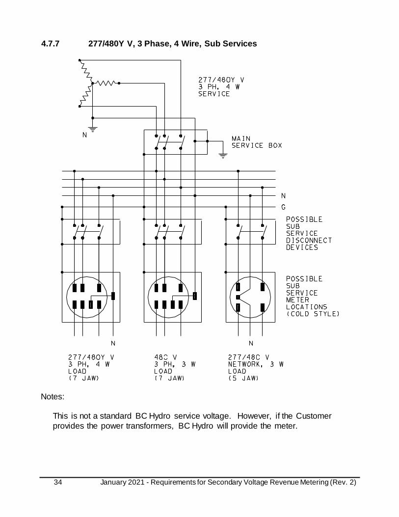
4.7.7 277/480Y V, 3 Phase, 4 Wire, Sub Services
Notes:
This is not a standard BC Hydro service voltage. However, if the Customer
provides the power transformers, BC Hydro will provide the meter.

35 January 2021 - Requirements for Secondary Voltage Revenue Metering (Rev. 2)
4.7.8 347/600Y V, 3 Phase, 4 Wire, Main Service

36 January 2021 - Requirements for Secondary Voltage Revenue Metering (Rev. 2)
4.7.9 347/600Y V, 3 Phase, 4 Wire, Sub Services

37 January 2021 - Requirements for Secondary Voltage Revenue Metering (Rev. 2)
4.7.10 240 V, 3 Phase, 3 Wire Delta, Main Service
Notes:
1. This is not a standard BC Hydro service voltage. However, if the
Customer provides the power transformers, BC Hydro will provide the
meter.
2. The above hot style configuration is applicable if the service fault current is
10,000 A or less. If the service fault current is greater than 10,000 A, the meter shall be on the load side of the main service box (cold style).

38 January 2021 - Requirements for Secondary Voltage Revenue Metering (Rev. 2)
4.7.11 480 V, 3 Phase, 3 Wire Delta, Main Service
Notes:
480 V, 3 Phase, 3 Wire Delta is not a standard BC Hydro service voltage. However,
if the Customer provides the power transformers, BC Hydro will provide a 480 V, 3
Phase, 3 Wire Delta Instrument Transformer Metering. See section 5.2.6.
4.7.12 600 V, 3 Phase, 3 Wire Delta, Main Service
600 V, 3 Phase, 3 Wire Delta is not a standard BC Hydro service voltage and BC
Hydro does not provide Self-Contained 600 V, 3 Phase, 3 Wire Delta meters for new services. However, if the Customer provides the power transformers, BC Hydro will
supply 600 V, 3 Phase, 3 Wire Delta Instrument Transformer Metering. See section
5.2.6.

39 January 2021 - Requirements for Secondary Voltage Revenue Metering (Rev. 2)
5. Instrument Transformer Metering
Instrument Transformer Metering is required for:
• All loads over 200 A; and
• 600 V, 3 Phase, 3 Wire, Delta services 200 A or less,
• 480 V, 3 Phase, 3 Wire, Delta services 200 A or less,
• Fire pump services >67h.p. (50 kW) – use ‘donut’ or ‘window‘ type CTs only
(See drawings 6.14 and 6.15)
5.1 General
a) Metered and unmetered conductors shall not be installed in the same
raceway, pull box or distribution gutter box.
b) The unmetered service conductor after main switch shall be continuous and
without access fittings or junction boxes up to the point of metering. This
precludes distribution gutter box as depicted in section 6.7.
c) Customer devices shall not be connected to BC Hydro VT and CT secondary
winding circuits and installed in designated BC Hydro compartment.
d) Power quality and load management devices including power factor
correction capacitors, surge protective devices, taps or any other devices
shall not be installed on the line side of BC Hydro billing meters.
e) The switchgear panel shall not have spare breakers except designated for
future metering of an area under construction and to be completed within 6 – 12 months.
For any spare breaker not meeting above, it shall be removed and covered by manufacturer supplied metal blanking plate.
5.1.1 1 Phase
Residential 1 Phase Services – Over 200A
400A Meter socket has CTs embedded and the meter by itself is a standard transformer rated meter with max 5A current.
Detached single family residential 1 phase services, over 200 A, shall only be
metered in an outdoor location using the following options:
• 120/240V 1 phase 400A meter socket assembly with an integral CT in accordance with section 5.5; or

40 January 2021 - Requirements for Secondary Voltage Revenue Metering (Rev. 2)
• Instrument transformer enclosure and Transformer-Type Meter Socket in accordance with section 5.3 and 5.7; or
• Switchgear instrument transformer compartment and Transformer-Type
Meter Socket in accordance with section 5.4.
The above are preferred point of metering arrangements. However, other
arrangements such as, located inside power shed or service closet on customer’s
property may be acceptable subject to approval from BC Hydro.
The above installations must be installed on the load side of customer owned
service equipment and as such must meet the latest requirements of BC Hydro,
the local electrical inspection authority and the BC Electrical Code Regulation. Approval from BC Hydro and the local inspection authority should be obtained
prior to finalizing plans for these services.
Other 1 Phase Services Over 200A
1 phase services, other than detached single family residential, shall be metered in
an indoor or outdoor location using the following options:
• Instrument transformer enclosure and Transformer-Type Meter Socket in accordance with section 5.3 and 5.7; or
• Switchgear instrument transformer compartment and Transformer-Type
Meter Socket in accordance with section 5.4; or
• 120/240V 1 phase 400A meter socket assembly with an integral CT in accordance with section 5.5.
Other arrangements such as, located inside a power shed or service closet on customer’s property may be acceptable subject to approval from BC Hydro.
The above installations must be installed on the load side of customer owned service equipment and as such must meet the latest requirements of BC Hydro,
the local electrical inspection authority and the BC Electrical Code Regulation.
Approval from BC Hydro and the local inspection authority should be obtained prior to finalizing plans for these services.
In accordance with section 5.8, where the instrument transformer enclosure/compartment is located indoors, the Transformer-Type Meter Socket or
the meter cabinet shall be located indoors in the same electrical/meter room as the
instrument transformer enclosure/compartment.
The instrument transformer enclosure/compartment and Transformer-Type Meter
Socket may be located indoors provided:

41 January 2021 - Requirements for Secondary Voltage Revenue Metering (Rev. 2)
• They are located in an electrical/meter room with a vertically hinged, lockable
door leading directly to the exterior of the building (roll-up or overhead garage
doors are not acceptable as access doors); • The accessibility arrangements for the exterior hinged door are agreed upon
by BC Hydro prior to approval.
5.1.2 3 Phase
5.1.2.1 Residential 3 Phase Services Over 200A
Detached single family residential 3 phase services shall be metered in an indoor or
outdoor location using the following options:
• Instrument transformer enclosure and Transformer-Type Meter Socket in
accordance with section 5.3.1; or • Switchgear instrument transformer compartment and meter Transformer-Type
Meter Socket in accordance with section 5.4;
Indoor detached single family residential metering is not preferred, however if agreed to be inside an electrical/meter room, direct access shall be arranged with
BC Hydro prior to approving proposed location. Other arrangements such as,
located inside a power shed or service closet on customer’s property may be acceptable subject to approval from BC Hydro.
The above installations must be installed on the load side of customer owned
service equipment and as such must meet the latest requirements of BC Hydro,
the local electrical inspection authority and the BC Electrical Code Regulation.
Get approval from BC Hydro and the local inspection authority prior to finalizing plans for these services.
The instrument transformer enclosure/compartment and Transformer-Type Meter Socket may be located indoors provided:
• They are located in an electrical/meter room with a vertically hinged, lockable
door leading directly to the exterior of the building (roll-up or overhead garage
doors are not acceptable as access doors);
• The accessibility arrangements for the exterior hinged door are agreed upon
by BC Hydro prior to approval.
In accordance with section 5.8, where the instrument transformer
enclosure/compartment is located indoors, the Transformer-Type Meter Socket shall be located indoors in the same electrical/meter room and within 3m of the instrument
transformer enclosure/compartment.

42 January 2021 - Requirements for Secondary Voltage Revenue Metering (Rev. 2)
5.1.2.2 Other 3 Phase Services Over 200A
3 phase services, other than detached single family residential, shall be metered in
an indoor or outdoor location using the following options:
• Instrument transformer enclosure and Transformer-Type Meter Socket in
accordance with section 5.3 and 5.7; or • Switchgear instrument transformer compartment and Transformer-Type
Meter Socket in accordance with section 5.4; or
Other arrangements such as, located inside a power shed or service closet on customer’s property may be acceptable subject to approval from BC Hydro.
The above installations must be installed on the load side of customer owned
service equipment and as such must meet the latest requirements of BC Hydro, the local electrical inspection authority and the BC Electrical Code Regulation.
Get approval from BC Hydro and the local inspection authority prior to finalizing
plans for these services.
The instrument transformer enclosure/compartment and Transformer-Type Meter
Socket may be located indoors provided:
• They are located in an electrical/meter room with a vertically hinged, lockable
door leading directly to the exterior of the building (roll-up or overhead garage
doors are not acceptable as access doors); • The accessibility arrangements for the exterior hinged door are agreed upon
by BC Hydro prior to approval. 5.2 Schematic Drawings
Instrument Transformer Metering shall be installed in accordance with the schematic
drawings in this section. The drawings illustrate a “main service box”. For sub
service applications, substitute a “sub service disconnect device” for the “main service box” and remove the neutral ground at the “sub service disconnect device”.

43 January 2021 - Requirements for Secondary Voltage Revenue Metering (Rev. 2)
5.2.1 120/240 V, 1 Phase, 3 Wire Service – Instrument Transformer
Enclosure or Compartment
Notes: 1. See section 5.3.1.1 and 5.3.2.1.
2. Approved sockets, CTS405PW-BC or CT105-L.
44 January 2021 - Requirements for Secondary Voltage Revenue Metering (Rev. 2)
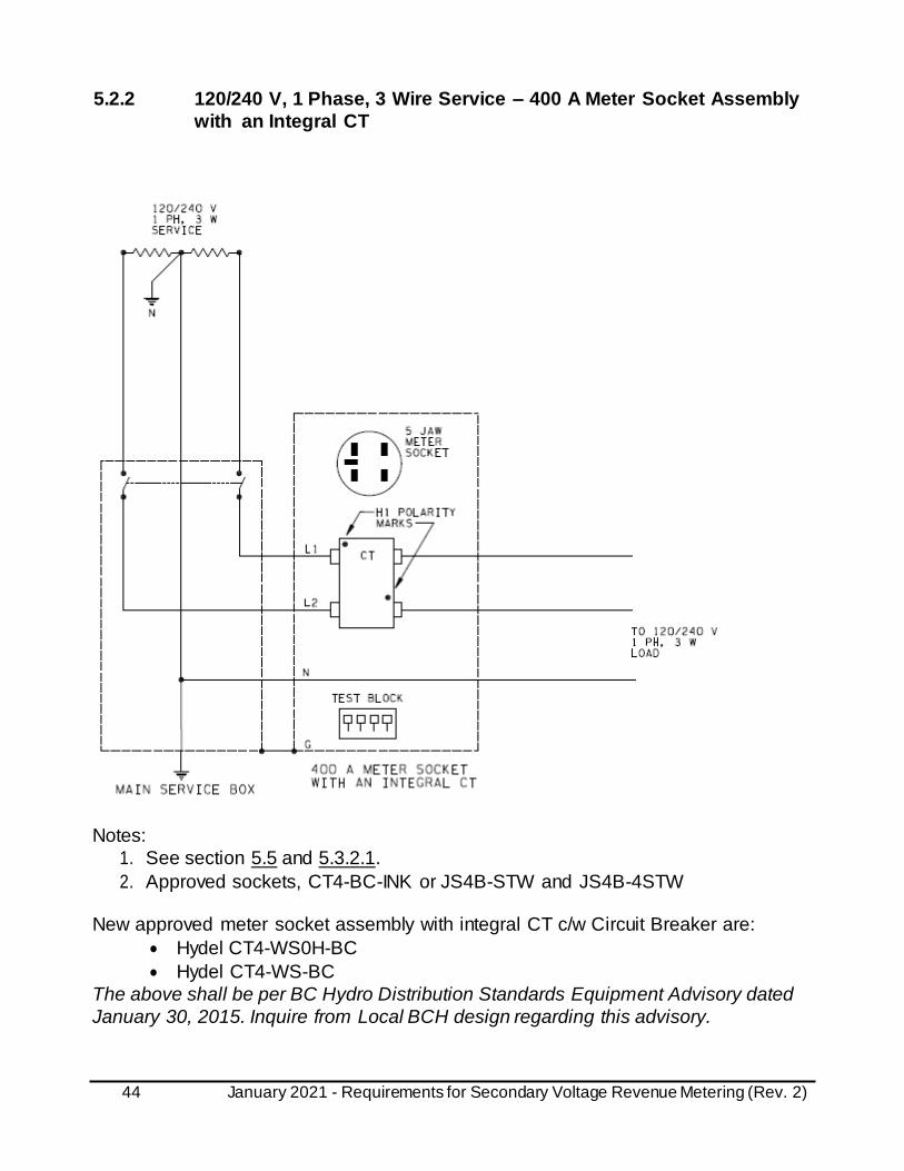
5.2.2 120/240 V, 1 Phase, 3 Wire Service – 400 A Meter Socket Assembly
with an Integral CT
Notes:
1. See section 5.5 and 5.3.2.1.
2. Approved sockets, CT4-BC-INK or JS4B-STW and JS4B-4STW
New approved meter socket assembly with integral CT c/w Circuit Breaker are:
• Hydel CT4-WS0H-BC
• Hydel CT4-WS-BC
The above shall be per BC Hydro Distribution Standards Equipment Advisory dated
January 30, 2015. Inquire from Local BCH design regarding this advisory.

45 January 2021 - Requirements for Secondary Voltage Revenue Metering (Rev. 2)
5.2.3 120/208Y V, 3 Phase, 4 Wire Service
Notes: 1. See section See section 5.3.1.2, 5.3.2.2., 5.4.1.2, or 5.4.2.2. 2. Approved sockets, CTS130PW-BC or CT113-L.

46 January 2021 - Requirements for Secondary Voltage Revenue Metering (Rev. 2)
5.2.4 277/480Y V or 347/600Y V, 3 Phase, 4 Wire Service
Notes:
1. See section 5.3.1.2, 5.3.2.2., 5.4.1.2, or 5.4.2.2.
2. Approved sockets, CTS130PW-BC or CT113-L.
3. BC Hydro will supply the VTs, CTs, and test switch for either a 277/480Y V or a 347/600Y V 3 phase, 4 wire service. However, BC Hydro does not supply the
power transformer for a 277/480Y V, 3 phase, 4 wire service.
4. VTs to be installed at the bottom of the Instrument Transformer Enclosure.

47 January 2021 - Requirements for Secondary Voltage Revenue Metering (Rev. 2)
5.2.5 240 V, 3 Phase, 3 Wire Delta Service
Notes:
1. See section 5.3.2.3, 5.3.2.4, 5.4.2.3, or 5.4.2.4.
2. Approved sockets, CTS800PW-BC or CT108-L.
3. BC Hydro does not supply the power transformers for this service. However, if
the Customer provides the power transformers, BC Hydro will supply the CTs
and meter.
48 January 2021 - Requirements for Secondary Voltage Revenue Metering (Rev. 2)
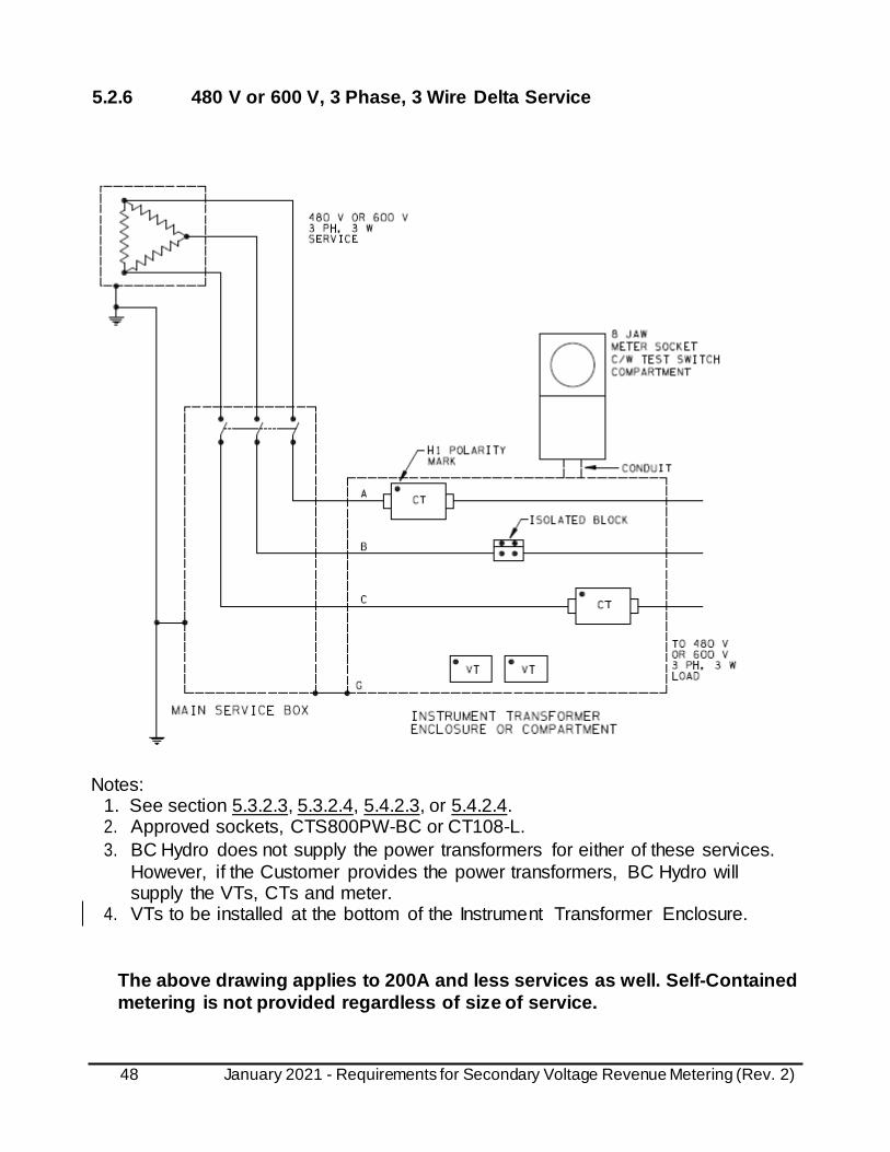
5.2.6 480 V or 600 V, 3 Phase, 3 Wire Delta Service
Notes: 1. See section 5.3.2.3, 5.3.2.4, 5.4.2.3, or 5.4.2.4. 2. Approved sockets, CTS800PW-BC or CT108-L.
3. BC Hydro does not supply the power transformers for either of these services.
However, if the Customer provides the power transformers, BC Hydro will supply the VTs, CTs and meter.
4. VTs to be installed at the bottom of the Instrument Transformer Enclosure.
The above drawing applies to 200A and less services as well. Self-Contained
metering is not provided regardless of size of service.

49 January 2021 - Requirements for Secondary Voltage Revenue Metering (Rev. 2)
5.3 Instrument Transformer Enclosure
5.3.1 Responsibility
5.3.1.1 1 Phase
a) The customer shall:
• Supply an instrument transformer enclosure
• Instrument transformer enclosure shall be installed in horizontal position in accordance with section 5.1.1.1, 5.1.1.2, and 6.9; and
• Supply and install a Hydel model CTS405PW-BC or a Microlectric model
CT105-L, 5 jaw Transformer-Type Meter Socket in accordance with section 5.7.1; and
• Supply and install a conduit between the instrument transformer enclosure
and the meter socket in accordance with section 5.8; and • Supply and install communication conduit and termination boxes as required in
section 3.2; and
• Install the CT(s) in accordance with section 5.6; and
• Make the CT primary connections in accordance with section 5.6
b) The BC Hydro will:
• Supply the CT(s); and BC Hydro standard mechanical connectors; and
• Supply and install the test block, meter, and metering wiring.
5.3.1.2 3 Phase
a) The customer shall:
• Supply an instrument transformer enclosure and an isolated neutral block
• Instrument transformer enclosure shall be installed in horizontal position in accordance with section 5.1.2.1, 5.1.2.2, and 6.10.
• Supply and install a Hydel model CTS800PW-BC (8 jaw), CTS130PW-BC
(13 jaw) or a Microlectric model CT108-L (8 jaw), CT113-L (13 jaw), Transformer-Type Meter Socket in accordance with section 5.7.1; and
• Supply and install a conduit between the instrument transformer enclosure
and the meter socket in accordance with section 5.8; and • Supply and install communication conduit and termination boxes as required in
section 3.2 and 6.17; and
• Install the CTs and VTs in accordance with section 5.6; and
• Make the CT primary connections in accordance with section 5.6

50 January 2021 - Requirements for Secondary Voltage Revenue Metering (Rev. 2)
b) The BC Hydro will:
• Supply the CTs; and BC Hydro standard mechanical connectors; and
• Where the phase-to-phase voltage is over 300 V:
• Supply the VTs; and • Make the VT primary connections; and
• Supply and install the test switch, meter, and metering wiring.
5.3.2 Equipment
a) The instrument transformer enclosure shall:
• Not be used as a splitter; and
• Shall be installed in horizontal position in accordance with section 6.9 and 6.10 with line entering and load exiting from the opposite ends. Where the
enclosure has to be installed in vertical position due to space constraint in an
existing installation, written approval shall be obtained from BC Hydro prior to installation.
• Not contain devices or connections other than the BC Hydro metering
equipment; and
• Be on the load side of the main service box or sub service disconnect device; and
• Be adjacent to the main service box or sub service disconnect device; and
• CTs and VTs are to be arranged and installed such that most efficient use of space inside the enclosure is accomplished; and
• Where located indoors, be in the same room as the main service box or sub
service disconnect device; and
• Where located outdoors, be weatherproof, padlockable, adjacent to the meter socket, and at least 900 mm from finished grade; and
• Be as close as practicable to the meter socket/cabinet (See section 5.8 for
the maximum separation distance); and
• Where located indoors, be in the same room as the meter socket/cabinet; and
• For 1 phase installations, be in accordance with the dimensional and other
requirements of section 6.9; and • For 3 phase installations, be in accordance with the dimensional and other
requirements of section 6.10; and
• Have flanged sides or hinged cover with provision for installation of BC Hydro wire seals; and
• Be permanently labelled as “BC Hydro Metering”; and
• Have provision for terminating a bonding conductor, within the enclosure, with either; • A 10-32 bonding screw and washer; or
• A mechanical connector suitable for a No.12 to No. 8 AWG conductor.

51 January 2021 - Requirements for Secondary Voltage Revenue Metering (Rev. 2)
The location of an instrument transformer enclosure for detached single family
residential services is restricted, See section 5.1.
b) The main service box or sub service disconnect device shall have provision for being locked open with 8 mm (5/16”) shank padlock.
c) For each point-of-metering, the same unique identifier shall be permanently
and legibly marked on each of the following:
• Main service box or sub service disconnect; and
• Instrument transformer enclosure; and
• Meter socket/cabinet.
In accordance with WorkSafe BC regulations, it is essential that each instrument
transformer enclosure point-of-isolation and meter socket/cabinet is explicitly and unambiguously identified to insure that it can be safely disconnected and locked out.
d) Where there is a potential for back energization from the load side of the
instrument transformer enclosure:
• Written approval shall be obtained from BC Hydro; and
• A CSA approved lockable disconnect device supplied by the
switchgear manufacturer shall be provided on the load side of the
instrument transformer enclosure; and
• The load side disconnect device shall meet the same requirements as the line side main service box or the line side sub service disconnect device;
and
• A warning notice shall be installed in a conspicuous place near the instrument transformer enclosure; and
• A permanent, legible single-line diagram shall be installed in a conspicuous
place near the instrument transformer enclosure.
Examples of the potential for back energization include:
• Where, by special permission from BC Hydro, there are multiple services
and/or points of metering and there is the potential for switching loads
between them;
• Where, by special permission from BC Hydro, the Customer has power generation that may be synchronized and/or closed transition momentarily
connected to BC Hydro.
However, where the Customer has generation connected via a CSA approved
transfer switch, no potential for back energization is deemed to exist and only a line
side disconnect device is required.

52 January 2021 - Requirements for Secondary Voltage Revenue Metering (Rev. 2)
5.3.2.1 120/240 V, 1 Phase, 3 Wire
a) For 120/240 V, 1 phase, 3 wire installations, the neutral is not part of the
metering circuit.
b) Where a single 3 wire bar type CT is supplied, it shall be installed in
accordance with section 6.11. Where two 2 wire bar type CTs are supplied,
they shall be installed in accordance with section 6.12.
See also the table in section 5.6.
5.3.2.2 3 Phase, 4 Wire Supply – 3 Phase 4 Wire Load
a) Where a 3 phase, 4 wire supply serves a 3 phase, 4 wire load, all neutral
conductor(s) shall be routed through (i.e. in and out) the instrument transformer enclosure. A neutral tap is not acceptable.
b) An isolated neutral block shall be supplied. Where multiple neutral cables are
used, only one of the cables is required to be connected to the isolated neutral
block. The isolated neutral block shall have either a 10-32 screw and washer
or it shall have a mechanical connector suitable for terminating three No. 12 AWG conductors. See section 6.13.
5.3.2.3 3 Phase, 4 Wire Supply – 3 Phase 3 Wire Load
a) Where a 3 phase, 4 wire supply serves a 3 phase, 3 wire load, the neutral
shall be extended to the instrument transformer enclosure. The minimum size of the neutral extension shall be No. 2/0 AWG copper.
b) The neutral extension shall terminate at an isolated neutral block. The isolated
neutral block shall have either a 10-32 screw and washer or it shall have a mechanical connector suitable for terminating three No. 12 AWG conductors.
See section 6.13.
5.3.2.4 3 Phase, 3 Wire Supply and Load
An isolated block shall be supplied for B phase. Where multiple cables are used, only one of the B phase cables is required to be connected to the isolated block. The
isolated block shall have either a 10-32 screw and washer or a mechanical connector
suitable for terminating two No. 12 AWG conductors.
53 January 2021 - Requirements for Secondary Voltage Revenue Metering (Rev. 2)
5.4 Switchgear Instrument Transformer Compartment
5.4.1 Responsibility
5.4.1.1 1 Phase
a) The customer shall:
• Supply and install an instrument transformer enclosure in accordance with section 5.1.1.1 and 5.1.1.2; and
• Supply and install a Hydel model CTS405PW-BC or a Microlectric model
CT105-L, 5 jaw Transformer-Type Meter Socket in accordance with
section 5.7.1; and • Supply and install a conduit between the instrument transformer enclosure
and the Transformer-Type Meter Socket in accordance with section 5.8;
and • Install the CT(s) in accordance with section 5.6; and
• Make the CT primary connections in accordance with section 5.6
b) The BC Hydro will:
• Supply the CTs; and • Supply and install the test block, meter, and metering wiring.
5.4.1.2 3 Phase
a) The customer shall:
• Supply and install an instrument transformer enclosure in accordance with
section 5.1.2.1 and 5.1.2.2; and • Supply and install a Hydel model CTS800PW-BC (8 jaw), CTS130PW-BC
(13 jaw) or a Microlectric model CT108-L (8 jaw), CT113-L (13 jaw)
Transformer-Type Meter Socket in accordance with section 5.7.1; and
• Supply and install a conduit between the instrument transformer enclosure and the Transformer-Type Meter Socket in accordance with section 5.8;
and • Install the CTs in accordance with section 5.6; and • Make the CT primary connections in accordance with section 5.6
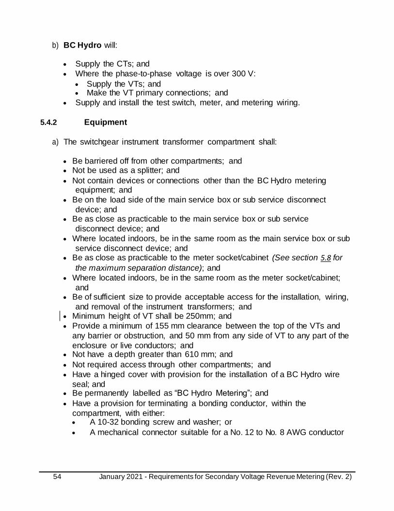
54 January 2021 - Requirements for Secondary Voltage Revenue Metering (Rev. 2)
b) BC Hydro will:
• Supply the CTs; and
• Where the phase-to-phase voltage is over 300 V:
• Supply the VTs; and • Make the VT primary connections; and
• Supply and install the test switch, meter, and metering wiring.
5.4.2 Equipment
a) The switchgear instrument transformer compartment shall:
• Be barriered off from other compartments; and • Not be used as a splitter; and
• Not contain devices or connections other than the BC Hydro metering equipment; and
• Be on the load side of the main service box or sub service disconnect
device; and • Be as close as practicable to the main service box or sub service
disconnect device; and
• Where located indoors, be in the same room as the main service box or sub
service disconnect device; and • Be as close as practicable to the meter socket/cabinet (See section 5.8 for
the maximum separation distance); and
• Where located indoors, be in the same room as the meter socket/cabinet;
and • Be of sufficient size to provide acceptable access for the installation, wiring,
and removal of the instrument transformers; and • Minimum height of VT shall be 250mm; and
• Provide a minimum of 155 mm clearance between the top of the VTs and
any barrier or obstruction, and 50 mm from any side of VT to any part of the
enclosure or live conductors; and • Not have a depth greater than 610 mm; and
• Not required access through other compartments; and
• Have a hinged cover with provision for the installation of a BC Hydro wire
seal; and • Be permanently labelled as “BC Hydro Metering”; and
• Have a provision for terminating a bonding conductor, within the
compartment, with either: • A 10-32 bonding screw and washer; or
• A mechanical connector suitable for a No. 12 to No. 8 AWG conductor
55 January 2021 - Requirements for Secondary Voltage Revenue Metering (Rev. 2)
Where the BC Hydro service is at a primary voltage level (4kV – 35kV), the main service box or sub service disconnect device may be on the primary of the Customer
power transformer.
The overall dimension of the instrument transformer compartment is not specified.
The use and location of an instrument transformer compartment for detached single
family residential services is restricted, See section 5.1.
b) The CTs shall be 600 to 1800 mm above the floor level.
This only applies to the mounting height of the CTs within the switchgear instrument transformer compartment. The bottom and top of the switchgear instrument
transformer compartment may be lower or higher.
c) The main service box or sub service disconnect device shall have provision for
being locked open with an 8 mm (5/16”) shank padlock.
d) For each point-of-metering, the same unique identifier shall be permanently
and legibly marked on each of the following:
• Main service box or sub service disconnect; and
• Instrument transformer compartment; and
• Meter socket.
In accordance with WorkSafe BC regulations, it is essential that each instrument
transformer compartment point-of-isolation and meter socket/cabinet is explicitly and
unambiguously identified to insure that it can be safely disconnected and locked out.
e) Where there is a potential for back energization from the load side of the
instrument transformer compartment:
• Written approval shall be obtained from BC Hydro; and
• A CSA approved lockable disconnect device supplied by the switchgear manufacturer shall be provided on the load side of the instrument
transformer compartment; and
• The load side disconnect device shall meet the same requirements as the
line side main service box or the line side sub service disconnect device; and
• A warning label shall be installed in a conspicuous place near the
instrument transformer compartment; and • A permanent, legible single-line diagram shall be installed in a conspicuous
place near the instrument transformer compartment; and

56 January 2021 - Requirements for Secondary Voltage Revenue Metering (Rev. 2)
Examples of the potential for back energization include:
• where, by special permission from BC Hydro, there are multiple services
and/or points of metering and there is the potential for switching loads between them;
• Where, by special permission from BC Hydro, the Customer has power
generation that may be synchronized, and/or closed transition momentarily
connected to BC Hydro.
However, where the Customer has generation connected via a CSA approved
transfer switch, no potential for back energization is deemed to exist and only a line side disconnect device is required.
5.4.2.1 120/240 V, 1 Phase, 3 Wire
a) For 120/240 V, 1 phase, 3 wire installations, the neutral is not part of the
metering circuit.
b) Where a single 3 wire bar type CT is supplied, it shall be installed in
accordance with section 6.11. Where two 2 wire bar type CTs are supplied,
they shall be installed in accordance with section 6.12.
See also the table in section 5.6.
5.4.2.2 3 Phase, 4 Wire Supply – 3 Phase 4 Wire Load
a) Where a 3 phase, 4 wire supply serves a 3 phase, 4 wire load;
• The neutral bus shall be routed through (i.e. in and out) the instrument
transformer compartment; or • A rigid neutral bus tap shall be provided from the neutral bus to the
instrument transformer compartment. The rigid neutral bus tap shall not be
less than 25 mm x 6 mm (1" x 1/4").
b) A 10-32 screw and washer shall be supplied at the following points:
• Line side of the A phase CT; and
• Line side of the B phase CT; and • Line side of the C phase CT; and
• Neutral bus or neutral tap.

57 January 2021 - Requirements for Secondary Voltage Revenue Metering (Rev. 2)
5.4.2.3 3 Phase, 4 Wire Supply – 3 Phase 3 Wire Load
a) Where a 3 phase, 4 wire supply serves a 3 phase, 3 wire load, the neutral bus
shall be extended to the instrument transformer compartment. The rigid neutral bus extension shall not be less than 25 mm x 6 mm (1" x 1/4").
b) A 10-32 screw and washer shall be supplied at the following points:
• Line side of the A phase CT; and • Line side of the B phase CT; and
• Line side of the C phase CT; and
• Neutral bus extension.
5.4.2.4 3 Phase, 3 Wire Supply and Load
A 10-32 screw and washer shall be supplied at the following points:
• Line side of the A phase CT; and
• B phase (2 x 10-32 screws); and • Line side of the C phase CT.
5.5 120/240 V, 1 Phase, 400 A Meter Socket Assembly with an Integral
CT
BC Hydro will allow the use of;
• 400A meter socket assembly with integral CT provided there is customer
service equipment with the means of disconnect installed adjacent and on the line side of metering; or
• 400A meter socket assembly with an integral CT c/w main disconnect.
5.5.1 Responsibility
a) The Customer shall:
• Supply and install a 120/240V, 1 Phase, 5 jaw, outdoor meter socket
assembly with an integral CT in a location acceptable to the BC Hydro’s Designer and the local electrical inspection authority; or
Model #s are; Hydel CT4-BC-INK, Microlectric JS4B-STW
• Supply and install a 120/240V,1 phase, 5 jaw outdoor rated meter socket assembly with an integral CT come with main min 22kA circuit breaker; and
Model #s are: Hydel CT4-WSOH-BC and CT4-WS-BC

58 January 2021 - Requirements for Secondary Voltage Revenue Metering (Rev. 2)
• Install the CT and primary connections in accordance with section 5.6.
b) The BC Hydro will:
• Supply the CT; and
• Supply and install the meter, test block and metering wiring.
5.5.2 Equipment
a) The 400 A meter socket shall be installed outdoors for residential services as
permitted on the load side of the service box with the neutral insulated.
• If the 400 A meter socket is wall mounted, it shall be one of the following
approved models:
Hydel CT4-BC-INK (5 jaw) c/w lexan barrier; or
T&B Microlectric JS4B-STW (5 jaw) c/w lexan barrier.
• If the 400 A meter socket is pole mounted, it shall be one of the following
approved models complete with the manufacturer supplied pole mounting kit:
Hydel CT4-BC (5 jaw) c/w lexan barrier plus CT4PMK36 pole mounting kit;
Hydel CT4-WSOH-BC or CT4-WS-BC (5 jaw) plus CT4PMK36 pole mounting kit or
T&B Microlectric JS4B-STW (5 jaw) c/w lexan barrier plus PMB-JS4 pole mounting
kit.
Any unused mounting holes shall be closed to prevent moisture or insect ingress.
The manufacturer supplied pole mounting kit insures that the 400 A meter socket is securely attached to the pole. Attaching “wall mount” 400 A meter sockets directly to
a pole with lag bolts or using a site fabricated bracket is prohibited.
b) The 400 A meter socket shall be mounted with the centre of the meter
between 1500 mm and 1800 mm above finished grade.
c) The 400 A meter socket bottom panel shall be secured with screws that
require a tool for removal.
Access to energized conductors, in the bottom panel, shall not rely only on the
presence of the BC Hydro seal and/or padlock.
Contact BC Hydro local design to get information on Distribution Standards Equipment Advisory for more information.

59 January 2021 - Requirements for Secondary Voltage Revenue Metering (Rev. 2)
5.6 Instrument Transformers
a) At 300 V phase-to-phase and less, current transformers (CTs) are required. At voltages greater than 300 V phase-to-phase, CTs and voltage transformers
(VTs) are required.
b) 600V and 480V 200A 3 phase 3 wire delta services will be metered using two VTs and two bar type CTs.
BC Hydro typically supplies the following CTs for permanent installations.
Location Supply System Min
Current
Max
Current
Qty Type Section
Indoor 120/240 V
1 Phase 3 Wire
300 A 600 A 1 3 Wire
Bar
6.11
800 A 1200 A 2 2 Wire
Bar
6.12
3 Phase
3 Wire 300 A 1200 A 2 2 Wire
Bar
-
1000 A 6000 A 2 Window 6.14
3 Phase
4 Wire
300 A 1200 A 3 2 Wire Bar
6.13
1000 A 6000 A 3 Window 6.14
Outdoor 120/240 V
1 Phase 3 Wire
300 A 800 A 2 Donut 6.15
6.16
3 Phase 3 Wire
300 A 800 A 2 Donut 6.15 6.16
3 Phase 4 Wire
300 A 800 A 3 Donut 6.15
6.16
Donut or Window CTs may be available for Temporary Construction indoor
installations (see drawings 6.14 and 6.15)
Normally these Temporary Construction CTs are removed when permanent revenue
meters are installed. Window CTs are only allowed in switchgear instrument transformer compartment, with the exception of fire pump service.
However, the Customer should check with BC Hydro to determine exactly which
CTs will be supplied for their installation.

60 January 2021 - Requirements for Secondary Voltage Revenue Metering (Rev. 2)
When BC Hydro supplies bar-type CTs for instrument transformer enclosures, they typically also supply the primary conductor connectors. However for muti-service
line and load conductors where BC Hydro supplied mechanical connectors are not
sufficient, a splitter box is required per BC Electrical Code.
A 3 Wire Bar CT has 4 primary connections. (see section 6.11)
c) The CT H1 primary terminal polarity marks shall be on the line side (towards
BC Hydro) in accordance with the schematic drawings in section 6.11.
d) The CT shall be mounted against the rear panel of the instrument
transformer enclosure/compartment using the provided CT base holes. “Hanging” window style CTs from the conductor, or using the primary terminals
to support bar style CTs, is not permitted. Mounting CTs to the side, top or bottom walls of the instrument transformer enclosure/compartment is not
permitted.
e) The conductors shall be shaped and supported in such a way to minimize
the mechanical stress applied to the CTs.
f) The VT and CT primary winding terminals and secondary winding terminals
shall remain accessible and the nameplates shall remain visible. The
installation shall facilitate the easy replacement of the VTs and CTs.
While nameplates must remain visible, terminal accessibility and polarity orientation
may position the nameplate upside-down or sideways. This is acceptable.
5.6.1 Metered fire pump service Loads >67h.p. (50kW)
Services for fire pumps equal or greater to 67 h.p.(50 kW) shall be metered with
instrument transformer metering using ‘donut’ or window style CTs only. (see sections 6.14 and 6.15)
(Fire pumps rated 66 h.p. (49 kW) or less will be unmetered and billed on a flat rated monthly consumption charge.)
5.7 Transformer-Type Meter Socket
5.7.1 Indoor/Outdoor Installations
a) The customer supplied Transformer-Type Meter Socket and the sealing ring
shall be certified in accordance with CSA Standard C22.2 No. 115, Meter
61 January 2021 - Requirements for Secondary Voltage Revenue Metering (Rev. 2)
Mounting Devices and they shall be approved by BC Hydro.
b) The Transformer-Type Meter Socket shall be installed, in a readily accessible
location approved by BC Hydro, in accordance with sections 3 and 5.1.
The sealing ring shall be a screw type in accordance with section 6.2.
The Transformer-Type Meter Socket shall be as close as practicable to the
instrument transformer enclosure/compartment and in the same room as the instrument transformer enclosure/compartment, see section 5.8 for the maximum
separation distance. For detached single family residential 1 phase services, section
5.1.1.1, requires that both the instrument transformer enclosure/compartment and the Transformer-Type Meter Socket be located outdoors.
c) One Transformer-Type Meter Socket is required for each 3 phase instrument
transformer point-of-metering.
d) The Transformer-Type Meter Socket tilt shall not exceed 3° from vertical.
e) All Transformer-Type Meter Socket in indoor location shall be mounted, using all
four predrilled holes meeting CEC, Part 1, Rule 6-408, on a 19 mm (¾”)
plywood backing.
All Transformer-Type Meter Sockets in outdoor location shall be wall mounted
on metal support channels.
The plywood or metal support channels shall be securely fastened to the wall.
Shooting, or otherwise mounting the meter socket, directly to the wall is not
permitted. Plywood backing for outdoor application will not be accepted.
f) The centre of the meter shall be mounted between 1,500 mm to 1,800 mm
above the finished grade.
A mounting height of 1,650 mm above finished grade is preferred.
g) Grounding lug(s) to be provided inside the Transformer-Type meter socket.
h) For pole mounted applications:
• The Transformer-Type Meter Socket shall be secured to the pole using the
manufacturer’s purpose built pole mounting bracket (e.g. Microlectric PMB200) with lag screws; and
• The Transformer-Type Meter Socket shall be located on the side of the pole
that is not subject to vehicle damage. If this is not practicable, protection

62 January 2021 - Requirements for Secondary Voltage Revenue Metering (Rev. 2)
posts shall be installed 600 mm in front of the Transformer-Type Meter Socket similar to those required under section 6.3.
i) The conduit shall enter the Transformer-Type Meter Socket from the bottom or
side where knockouts provided.
j) The conduit shall not be entered from the back of the Transformer-Type Meter
Socket.
k) Transformer-Type Meter Socket shall not be installed within 1000 mm of gas
meters or within 3000 mm of propane meters, tanks, regulators or relief devices.
5.7.2 Grounding
a) In accordance with section 36 of the Canadian Electrical Code, an external
ground conductor shall be provided for the Transformer-Type Meter Socket if:
• The associated instrument transformer compartment is within a unit
substation with a high voltage (greater than 750 V) section; or
• The Transformer-Type Meter Socket is within the same room as high voltage equipment.
b) Where required, the external Transformer-Type Meter Socket ground
conductor shall not be less than No. 2/0 AWG copper and shall be connected
to the station ground grid electrode.
A No. 2/0 AWG copper conductor is required since, due to skin effect, its large surface
area provides a low impedance path for high frequency electrical noise.
5.7.3 Optional Meter Compartment
The optional meter compartment shall use the Transformer-Type Meter Socket in
accordance with the following:
a) Be completely separate from the instrument transformer enclosure; b) The meter socket is permitted to be installed within the exterior side of
switchgear;
c) The recessed depth is less than the depth of the Transformer-Type Meter Socket, i.e. the cover shall project beyond the finished exterior wall surface;
and
d) Recessing does not interfere with the installation, reading or removal of the meter; and
e) Recessing does not interfere with the installation or removal of the
Transformer-Type Meter Socket cover.
f) The Transformer-Type Meter Socket may be installed on the exterior of the switchgear provided there are adequate measures taken to protect against

63 January 2021 - Requirements for Secondary Voltage Revenue Metering (Rev. 2)
damages. g) The Customer shall provide a continuous Metal or Rigid PVC conduit, without
access fittings, between the optional meter compartment and the instrument
transformer compartment as per section 5.8.
h) The conduit shall enter from the bottom of the meter socket.
Seek prior approval from BC Hydro designer prior to considering this option. 5.8 Conduit
a) The Customer shall supply and install a conduit between the Transformer-
Type meter socket and the instrument transformer enclosure/compartment.
The Transformer-Type meter socket shall be as close as practicable to the
instrument transformer enclosure/compartment and in the same room as the instrument transformer enclosure/compartment.
Where the instrument transformer enclosure is located outdoor, conduit shall exit
from the bottom of the instrument transformer enclosure to the Transformer- Type meter socket.
b) The conduit shall be either rigid metal, EMT or rigid PVC.
ENT (electrical non-metallic tubing) is not permitted.
c) The conduit shall not have more than the equivalent of three 90° bends.
d) For 1 phase installations, the conduit length shall not exceed 3 m (10’) and the
minimum trade size shall be 21 (3/4”).
e) For 3 phase installations, the conduit length shall not exceed 10 m (33’) and
the minimum trade size shall be 35 (1 ¼”). Except that, where special written approval is first obtained from BC Hydro, a 41 (1 ½”) conduit with a length of
between 10 m (33’) and 25 m (82’) may be installed.
f) The conduit shall be continuous and without access fittings. Except that, an “(LB, LL, and LR) style” fitting may be installed immediately adjacent to the meter socket providing the fitting’s cover:
• Remains clearly visible; and • Has provision for the installation of a BC Hydro wire seal.
Or as an alternative,
64 January 2021 - Requirements for Secondary Voltage Revenue Metering (Rev. 2)
• Elbow 90 with minimum trade size 41 (1 ½”) shall be installed immediately adjacent to the meter socket.
g) The conduit shall remain visible for its entire length except where it is
embedded in a concrete floor or ceiling within the same room.
Conduits shall not be installed through walls or underground.
h) For switchgear applications, where it is necessary to route the conduit through
other switchgear compartments, Customer shall provide a continuous metal or rigid PVC conduit, without access fittings, within the switchgear. Given this, if it
is necessary to route through the service entry (wireway) compartment, the
conduit shall enter and exit from either sides all the way towards the back of
the compartment in order not to obstruct any cable pulling and/or termination.
i) The Customer shall leave a pull string in the conduit.

65 January 2021 - Requirements for Secondary Voltage Revenue Metering (Rev. 2)
6. Reference Drawings
6.1 Underground Main Service Meter Sockets
Mandatory for new 200 & 400A multiple underground services.
66 January 2021 - Requirements for Secondary Voltage Revenue Metering (Rev. 2)
Notes:
For U/G services the following apply:
1. 200A & 400A,1 phase, multiple main service enclosures shall have one extra compartment for service entry supply conductors.
2. See section 3.7.
3. They are not applicable to single overhead, main service meter sockets or to sub service meter sockets.
4. Metered and unmetered conductors shall not be crossed as per
Distribution Standards. 5. Dimensions are in mm.

67 January 2021 - Requirements for Secondary Voltage Revenue Metering (Rev. 2)
6.2 Sealing Ring
Notes:
See section 4.1.

68 January 2021 - Requirements for Secondary Voltage Revenue Metering (Rev. 2)
6.3 Individual Pole Mounted Meter Socket
Notes: 1. See section 4.2.6.
2. Mast shall remain visible throughout its entire length.

69 January 2021 - Requirements for Secondary Voltage Revenue Metering (Rev. 2)
6.4 Individual Wall Mounted Meter Socket Near a Gas or Propane Meter
Notes:
1. See section 4.2.7.
2. Propane meter/devices includes any propane stationary tank. 3. Not to scale drawings.

70 January 2021 - Requirements for Secondary Voltage Revenue Metering (Rev. 2)
6.5 Multiple Main Meter Socket
Notes: 1. See section 4.3.
2. Underground service illustrated.

71 January 2021 - Requirements for Secondary Voltage Revenue Metering (Rev. 2)
6.6 Meter Centre
Notes: 1. See section 4.4.

72 January 2021 - Requirements for Secondary Voltage Revenue Metering (Rev. 2)
6.7 Grouped Sub Service Metering
Notes: 1. See section 4.5.
2. Cold style metering with the meter socket on the load side of the sub service
disconnect device and with the neutral isolated at the meter socket is required.
3. Each meter socket shall be adjacent to, and as close as practicable to, the controlling sub service disconnect device and in the same room as the controlling
sub service disconnect device.
4. Contact BC Hydro and refer to the ES53 Series Underground Electrical standards and the ES54 Underground Civil standards for underground main service conduit,
wireway and pull box requirements.
5. Multiple Self-Contained Metering and multiple Instrument Transformer Metering
are allowed.

73 January 2021 - Requirements for Secondary Voltage Revenue Metering (Rev. 2)
6.8 Service Pedestal
Notes: 1. See section 4.6.

74 January 2021 - Requirements for Secondary Voltage Revenue Metering (Rev. 2)
6.9 120/240 V, 1 Phase, Instrument Transformer Enclosure
Notes:
1. The following minimum 120/240 V, 1 phase instrument transformer enclosure dimensions shall be provided.
Main Switch Size Enclosure Size (W x H x D)
400 A or Less 760 mm x 420 mm x 205 mm (30” x 16” x 8”)
Over 400 A 1065 mm x 460 mm x 405 mm (42” x 18” x 16”)
2. The customer shall supply and install a 5 jaw meter socket
3. Illustrated equipment locations may vary provided the specified dimensions are achieved.
4. The instrument transformer enclosure shall be in the same room, adjacent to, and as close as practicable to, the main service box or sub service disconnect device.
5. The meter socket shall be in the same room, adjacent to, and as close as
practicable to the instrument transformer enclosure.
6. Contact BC Hydro and refer to the ES53 Series Underground Electrical standards and the ES54 Underground Civil standards for underground main service conduit,
wireway and pull box requirements.
7. The instrument transformer enclosure shall be installed in horizontal position with line entering and load exiting from A to A’ (preferred option), B to B’, C to C’, B to C’, C to B’, A to B’, A to C’, B to A’, or C to A’ as depicted in the diagram.

75 January 2021 - Requirements for Secondary Voltage Revenue Metering (Rev. 2)
6.10 3 Phase Instrument Transformer Enclosure

76 January 2021 - Requirements for Secondary Voltage Revenue Metering (Rev. 2)
Notes:
1. The following minimum 3 phase instrument transformer enclosure dimensions
shall be provided.
Main Switch Size Voltage Enclosure Size (W x H x D)
400 A to 600 A All 1065 mm x 460 mm x 405 mm (42” x 18” x 16”)
601 A to 1,000 A All 1065 mm x 915 mm x 610 mm
(42” x 36” x 24”)
Over 1,000 A All Use switchgear instrument transformer compartment or an approved engineered
assembly complete with consultant’s drawings
BC Hydro is phasing out the 30” x 16” x 8” instrument transformer enclosure for
3 phase installation. Starting from April 15th, 2019, this enclosure will no longer be accepted.
2. Illustrated equipment locations may vary provided the specified dimensions are achieved.
3. The Instrument transformer enclosure shall be in the same room, adjacent to,
and as close as practicable to, the main service box or sub service disconnect
device. 4. The customer supplied meter socket shall be in the same room, adjacent to, and
as close as practicable to the instrument transformer enclosure.
5. Contact BC Hydro and refer to the ES53 Series Underground Electrical standards and the ES54 Underground Civil standards for underground main
service conduit, wireway and pull box requirements. 6. The instrument transformer enclosure shall be installed in horizontal position with
line entering and load exiting from A to A’ (preferred option), B to B’, C to C’, B to
C’, C to B’, A to B’, A to C’, B to A’, or C to A’ as depicted in the diagram.

77 January 2021 - Requirements for Secondary Voltage Revenue Metering (Rev. 2)
6.11 120/240 V, 1 Phase, Metering with a Single 3 Wire Bar Type CT
Notes: 1. Contractors are required to use only BC Hydro supplied standard mechanical
connectors.
2. See section 5.3.2.1.
3. The actual polarity markings may be different. Consult with the Local Design or
Metering Technician should there be any question.
4. The mechanical connectors (lugs) shall be installed in-line with the CT bus bar per above diagram.

78 January 2021 - Requirements for Secondary Voltage Revenue Metering (Rev. 2)
6.12 120/240 V, 1 Phase, Metering with Two 2 Wire Bar Type CTs
Notes:
1. Contractors are required to use only BC Hydro supplied standard mechanical
connectors. 2. See section 5.3.2.1.
3. Polarity marks shall be towards the line side.
4. The mechanical connectors (lugs) shall be installed in-line with the CT bus bar per above diagram.

79 January 2021 - Requirements for Secondary Voltage Revenue Metering (Rev. 2)
6.13 3 Phase, 4 Wire, Metering with Bar Type CTs
Notes: 1. Contractors are required to use only BC Hydro supplied standard mechanical
connectors. 2. See section 5.3.2.
3. Polarity marks shall be towards the line side.
4. It is a requirement that CTs are staggered for most efficient use of space, thereby reducing increased bending radius and ease of wiring of secondary
terminals.
5. The mechanical connectors (lugs) shall be installed in-line with the CT bus bar per above diagram.

80 January 2021 - Requirements for Secondary Voltage Revenue Metering (Rev. 2)
6.14 Typical Indoor Window CT
Notes:
1. See section 5.6.

81 January 2021 - Requirements for Secondary Voltage Revenue Metering (Rev. 2)
6.15 Typical Indoor/Outdoor Donut CT
Notes:
1. See section 5.6.

82 January 2021 - Requirements for Secondary Voltage Revenue Metering (Rev. 2)
6.16 General Arrangement of Meter Inside Electrical/Meter Room
Notes:
1. Grouped sub service meters shall be installed inside an electrical/meter room. See section 3.2.
2. At least one meter socket in the electrical room shall be mounted in such
location as shown above, facing an exterior wall preferably without obstruction.

83 January 2021 - Requirements for Secondary Voltage Revenue Metering (Rev. 2)
6.17 Meter Connection to RF Mesh Network
Notes:
1. See section 3.2. The above is only required for one meter inside elec. room
2. All material/connections from Termination box to meter is BCH responsibility.

84 January 2021 - Requirements for Secondary Voltage Revenue Metering (Rev. 2)
6.18 Multiple Meter Rooms Conduit Arrangement
Notes:
1. Alternate arrangement is to run conduit from Main Meter Room 1 to Meter Room
2, and from Meter Room 2 to Meter Room 3 in a daisy chain configuration, instead of Main Meter Room 1 to Meter Room 3.
2. See section 3.2.
3. Conduit run between meter rooms exceeding 100m requires installation of additional pull box similar to above termination box dimension and set up.

85 January 2021 - Requirements for Secondary Voltage Revenue Metering (Rev. 2)
6.19 Multiple Meter Rooms on Multiple Levels Conduit Arrangement
Notes: 1. Alternate arrangement is to run conduit from Main Meter Room 1 to Meter Room
2, and from Meter Room 2 to Meter Room 3 in a daisy chain configuration,
instead of Main Meter Room 1 to Meter Room 3.
86 January 2021 - Requirements for Secondary Voltage Revenue Metering (Rev. 2)
7 Definitions
Except where noted below, definitions shall be in accordance with Canadian Electrical
Code.
Instrument Transformer means a high accuracy Voltage Transformer (VT) or
Current Transformer (CT) that transforms the metered circuit voltage and current to
lower levels for connection to an instrument transformer type meter. Metering VTs and
CTs secondaries are 120V and 5A respectively.
Instrument Transformer Metering means a metering installation where the meter is connected to the metered circuit conductors via instrument transformers.
Meter Cabinet means the previously BC Hydro supplied cabinet for mounting a 3 phase instrument transformer meter. Meter cabinet is currently no longer
supplied by BC Hydro.
Meter Socket means the Customer supplied device for mounting a Self-Contained
meter. The meter socket is referred to as the meter mounting device in the Canadian
Electrical Code.
Indoor Meter Closet means a small electrical room with one or more meter centre(s)
and/or bases and may consist of a dry-type transformer.
Network Service means a service consisting of two phase conductors plus a
neutral conductor supplied from a standard 3 phase, 4 wire distribution power system.
Premises means a building, a separate unit of a building, a dwelling or machinery,
together with the surrounding land.
Self-Contained Metering means a metering installation where the meter is installed directly in series with the circuit conductors.
Transformer-Type Meter Socket means the Customer supplied meter socket c/w test switch compartment in various jaw configurations required to install BC Hydro supplied test switch and meter for Instrument Transformer Metering. The meter socket is referred to as the meter mounting device in the Canadian Electrical Code.

87 January 2021 - Requirements for Secondary Voltage Revenue Metering (Rev. 2)
To view the latest revision of this document go to: http://www.bchydro.com