Embed Size (px)
Citation preview
1
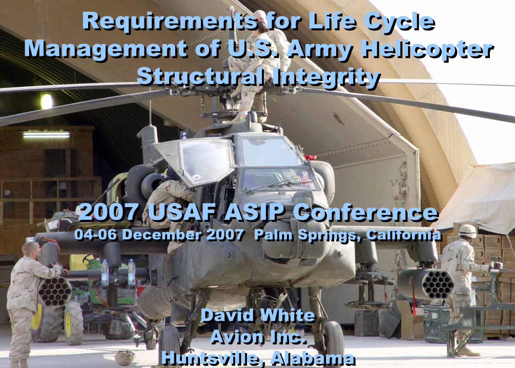
David WhiteAvion Inc.
Huntsville, Alabama
David WhiteAvion Inc.
Huntsville, Alabama
Requirements for Life Cycle Management of U.S. Army Helicopter
Structural Integrity
Requirements for Life Cycle Management of U.S. Army Helicopter
Structural Integrity
2007 USAF ASIP Conference04-06 December 2007 Palm Springs, California2007 USAF ASIP Conference04-06 December 2007 Palm Springs, California
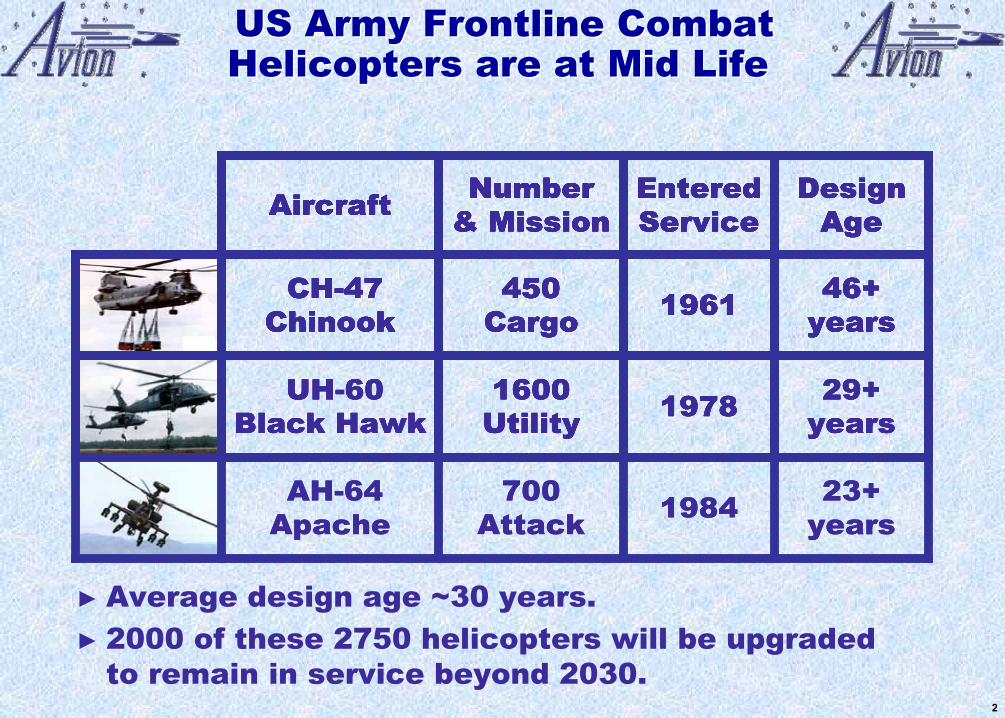
450 Cargo
Number & Mission
CH-47 Chinook
Aircraft
46+ years1961
Design Age
Entered Service
450 Cargo
Number & Mission
CH-47 Chinook
Aircraft
46+ years1961
Design Age
Entered Service
1600 Utility
450 Cargo
Number & Mission
UH-60 Black Hawk
CH-47 Chinook
Aircraft
29+ years1978
46+ years1961
Design Age
Entered Service
1600 Utility
450 Cargo
Number & Mission
UH-60 Black Hawk
CH-47 Chinook
Aircraft
29+ years1978
46+ years1961
Design Age
Entered Service
700 Attack
1600 Utility
450 Cargo
Number & Mission
AH-64 Apache
UH-60 Black Hawk
CH-47 Chinook
Aircraft
23+ years1984
29+ years1978
46+ years1961
Design Age
Entered Service
700 Attack
1600 Utility
450 Cargo
Number & Mission
AH-64 Apache
UH-60 Black Hawk
CH-47 Chinook
Aircraft
23+ years1984
29+ years1978
46+ years1961
Design Age
Entered Service
► Average design age ~30 years. ► 2000 of these 2750 helicopters will be upgraded
to remain in service beyond 2030.
US Army Frontline Combat Helicopters are at Mid LifeUS Army Frontline Combat Helicopters are at Mid Life
2

Operational Usage Severity Has Increased DramaticallyOperational Usage Severity Has Increased Dramatically
► High Altitude► Desert Sand
Army helicopters must remain available, safe, and affordable... ► while flying combat OPTEMPO of 3-4x peacetime...► in increasingly harsh environments.
► Ship Operations► Salt Environment
► Combat Maneuvers► Expanded Envelope
3
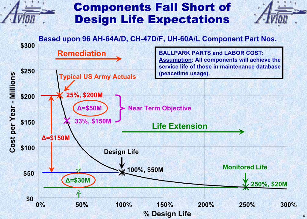
Components Fall Short of Design Life ExpectationsComponents Fall Short of Design Life Expectations
100%, $50M
Design Life
Based upon 96 AH-64A/D, CH-47D/F, UH-60A/L Component Part Nos.
$00% 50% 100% 150% 200% 250% 300%
% Design Life
$50
$100
$150
$200
$300
Cos
t per
Yea
r -M
illio
ns
$250
BALLPARK PARTS and LABOR COST:Assumption: All components will achieve the service life of those in maintenance database (peacetime usage).
Remediation
Δ=$150M
25%, $200M
Typical US Army Actuals
250%, $20M
Monitored Life
Δ=$30M
Life Extension33%, $150M
Δ=$50M Near Term Objective
4
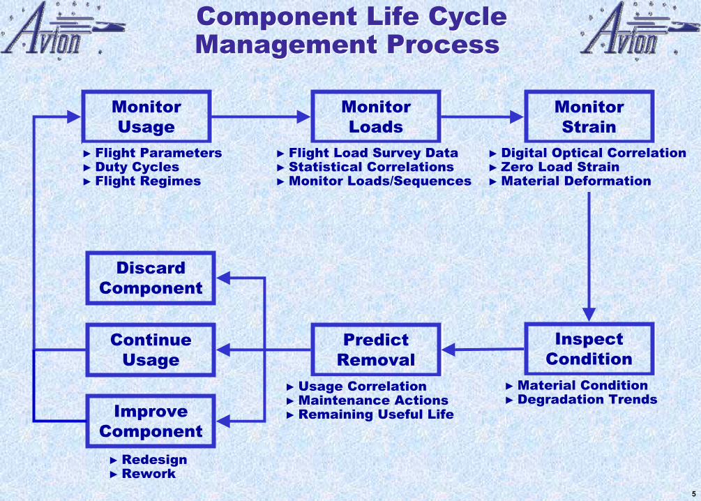
► Redesign► Rework
ImproveComponent
ContinueUsage
Discard Component
Inspect ConditionInspect
Condition► Material Condition► Degradation Trends
Predict RemovalPredict
Removal► Usage Correlation► Maintenance Actions► Remaining Useful Life
Monitor Usage
Monitor Usage
► Flight Parameters► Duty Cycles► Flight Regimes
Monitor Loads
Monitor Loads
► Flight Load Survey Data► Statistical Correlations► Monitor Loads/Sequences
Component Life Cycle Management ProcessComponent Life Cycle Management Process
Monitor Strain
Monitor Strain
► Digital Optical Correlation► Zero Load Strain► Material Deformation
5
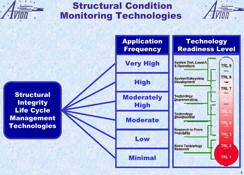
Structural ConditionMonitoring Technologies
Structural ConditionMonitoring Technologies
Structural Integrity
Life Cycle Management Technologies
Very High
Minimal
Low
Moderate
Moderately High
High
Application Frequency
Technology Readiness Level
6
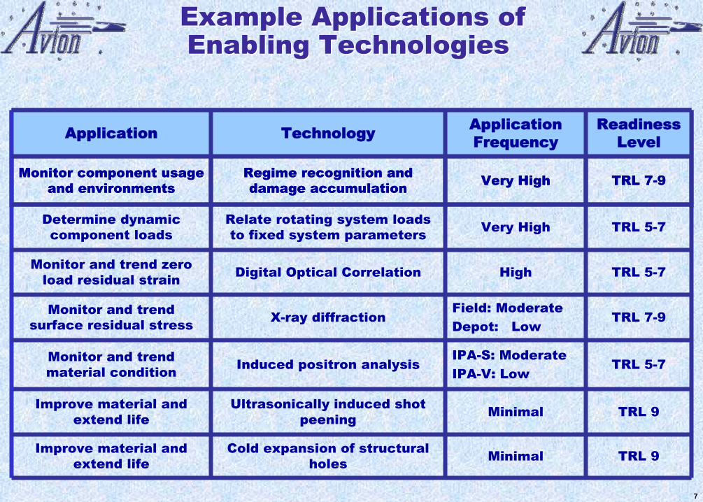
TRL 5-7HighDigital Optical CorrelationMonitor and trend zero load residual strain
TRL 7-9Field: ModerateDepot: Low
X-ray diffractionMonitor and trend surface residual stress
TRL 9MinimalUltrasonically induced shot peening
Improve material and extend life
Cold expansion of structural holes
Induced positron analysis
Relate rotating system loads to fixed system parameters
Regime recognition and damage accumulation
Technology
TRL 9MinimalImprove material and extend life
TRL 5-7IPA-S: ModerateIPA-V: Low
Monitor and trend material condition
TRL 5-7Very HighDetermine dynamic component loads
TRL 7-9Very HighMonitor component usage and environments
Readiness Level
Application FrequencyApplication
Example Applications ofEnabling TechnologiesExample Applications ofEnabling Technologies
TRL 5-7HighDigital Optical CorrelationMonitor and trend zero load residual strain
TRL 7-9Field: ModerateDepot: Low
X-ray diffractionMonitor and trend surface residual stress
TRL 9MinimalUltrasonically induced shot peening
Improve material and extend life
Cold expansion of structural holes
Induced positron analysis
Relate rotating system loads to fixed system parameters
Regime recognition and damage accumulation
Technology
TRL 9MinimalImprove material and extend life
TRL 5-7IPA-S: ModerateIPA-V: Low
Monitor and trend material condition
TRL 5-7Very HighDetermine dynamic component loads
TRL 7-9Very HighMonitor component usage and environments
Readiness Level
Application FrequencyApplication
7
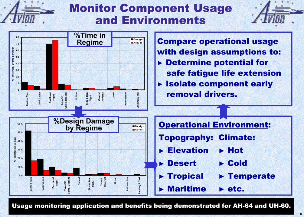
Operational Environment: Topography: Climate:► Elevation ► Hot► Desert ► Cold► Tropical ► Temperate► Maritime ► etc.
+
% Total D esign D am age by R eg im e
0%
10%
20%
30%
40%
50%
60%
Ban
ked
Turn
GA
G C
ycle
s
Fwd
Leve
lFl
ight
Take
-Off,
Clim
b, D
esce
nt
Pullo
ut
Side
& R
ear
Flig
ht
Con
trol
Rev
ersa
l
Hov
er
Aut
orot
atio
n
Land
ing
& T
axi
%To
tal D
esig
n D
amag
e
D esignActual
%Design Damage by Regime
Tim e in R egim e
0
10
20
30
40
50
60
70
80
Ban
ked
Turn
GA
G C
ycle
s
Fwd
Leve
lFl
ight
Take
-Off,
Clim
b, D
esce
nt
Pullo
ut
Side
& R
ear
Flig
ht
Con
trol
Rev
ersa
l
Hov
er
Aut
orot
atio
n
Land
ing
& T
axi
%Ti
me
or N
o. E
vent
s pe
r Hou
r
DesignActual
%Time in Regime
Monitor Component Usageand Environments
Monitor Component Usageand Environments
Compare operational usage with design assumptions to: ► Determine potential for
safe fatigue life extension► Isolate component early
removal drivers.
Usage monitoring application and benefits being demonstrated for AH-64 and UH-60.8
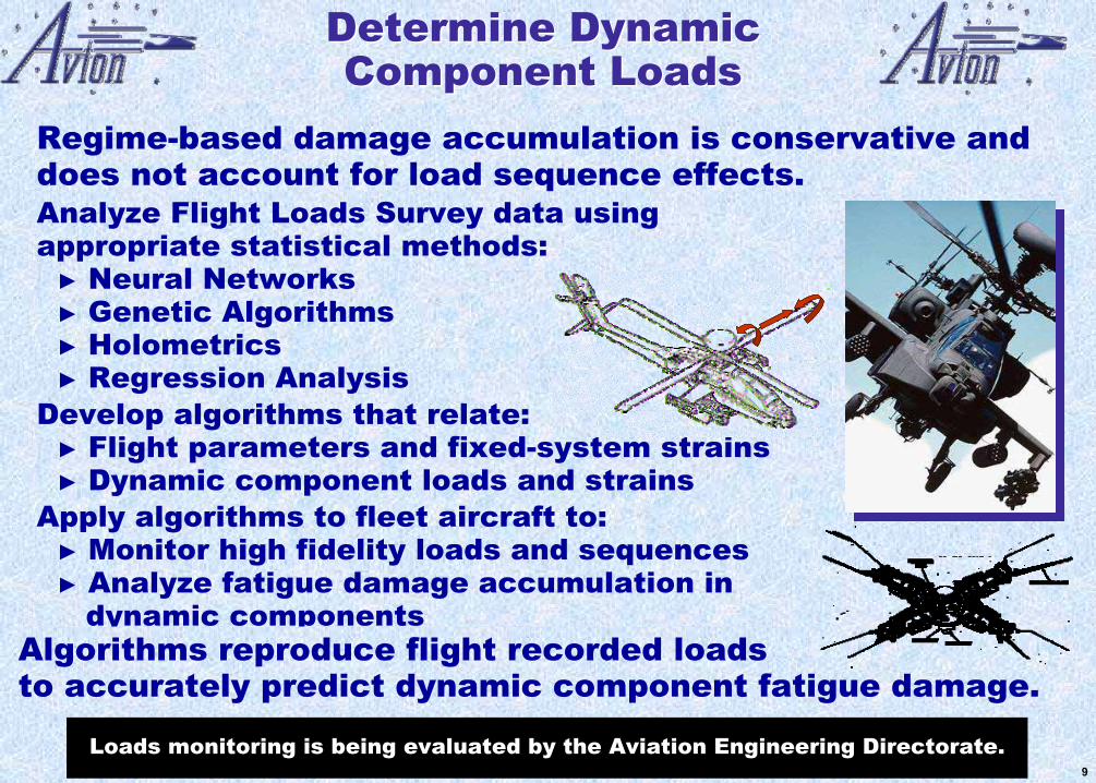
Determine Dynamic Component Loads
Determine Dynamic Component Loads
Regime-based damage accumulation is conservative and does not account for load sequence effects.Analyze Flight Loads Survey data using appropriate statistical methods:► Neural Networks► Genetic Algorithms► Holometrics► Regression Analysis
Develop algorithms that relate:► Flight parameters and fixed-system strains► Dynamic component loads and strains
Apply algorithms to fleet aircraft to:► Monitor high fidelity loads and sequences ► Analyze fatigue damage accumulation in
dynamic componentsAlgorithms reproduce flight recorded loads to accurately predict dynamic component fatigue damage.
Loads monitoring is being evaluated by the Aviation Engineering Directorate.9
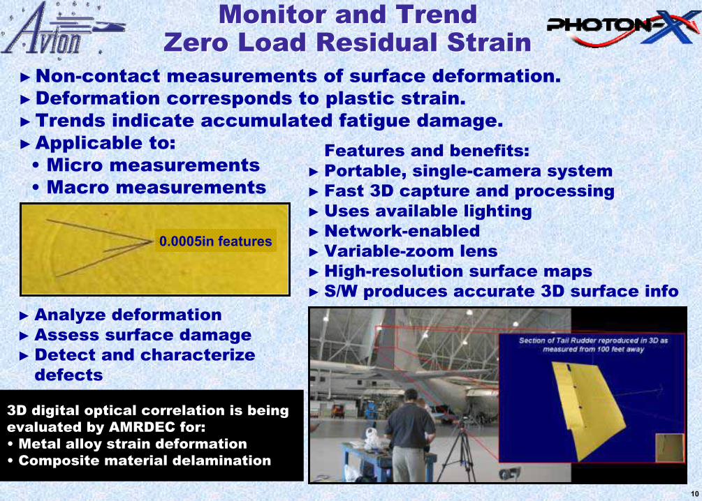
Monitor and TrendZero Load Residual Strain
Monitor and TrendZero Load Residual Strain
Features and benefits: ► Portable, single-camera system► Fast 3D capture and processing ► Uses available lighting► Network-enabled ► Variable-zoom lens► High-resolution surface maps ► S/W produces accurate 3D surface info
►Non-contact measurements of surface deformation.►Deformation corresponds to plastic strain.►Trends indicate accumulated fatigue damage. ►Applicable to:
• Micro measurements• Macro measurements
0.0005in features
► Analyze deformation ► Assess surface damage► Detect and characterize
defects
3D digital optical correlation is being evaluated by AMRDEC for:• Metal alloy strain deformation• Composite material delamination
10
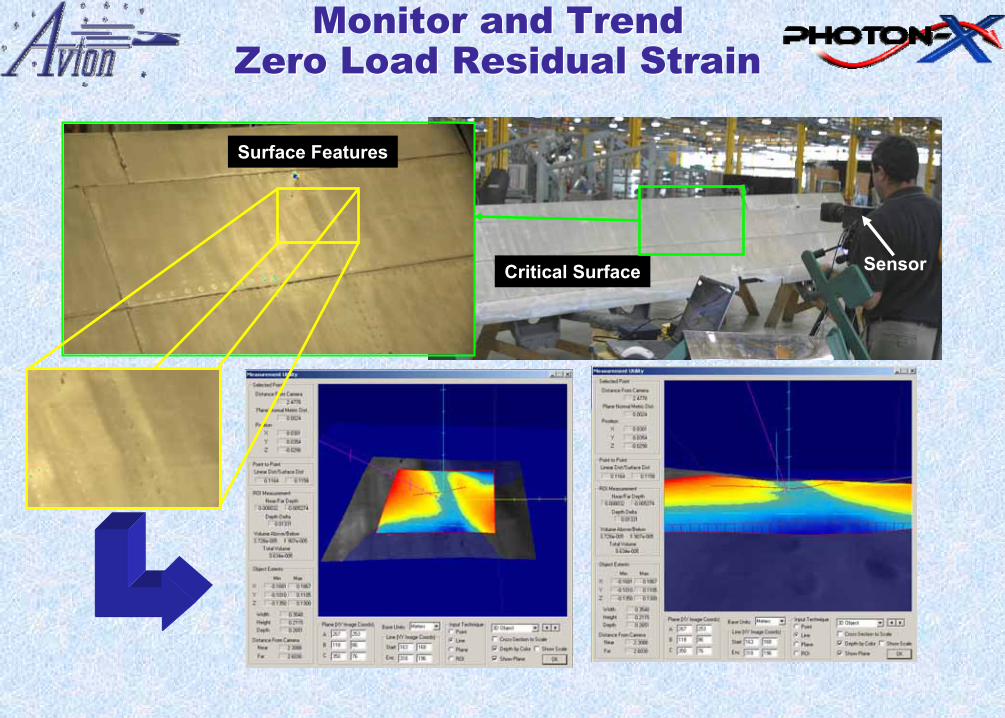
SensorCritical Surface
Surface Features
Monitor and TrendZero Load Residual Strain
Monitor and TrendZero Load Residual Strain
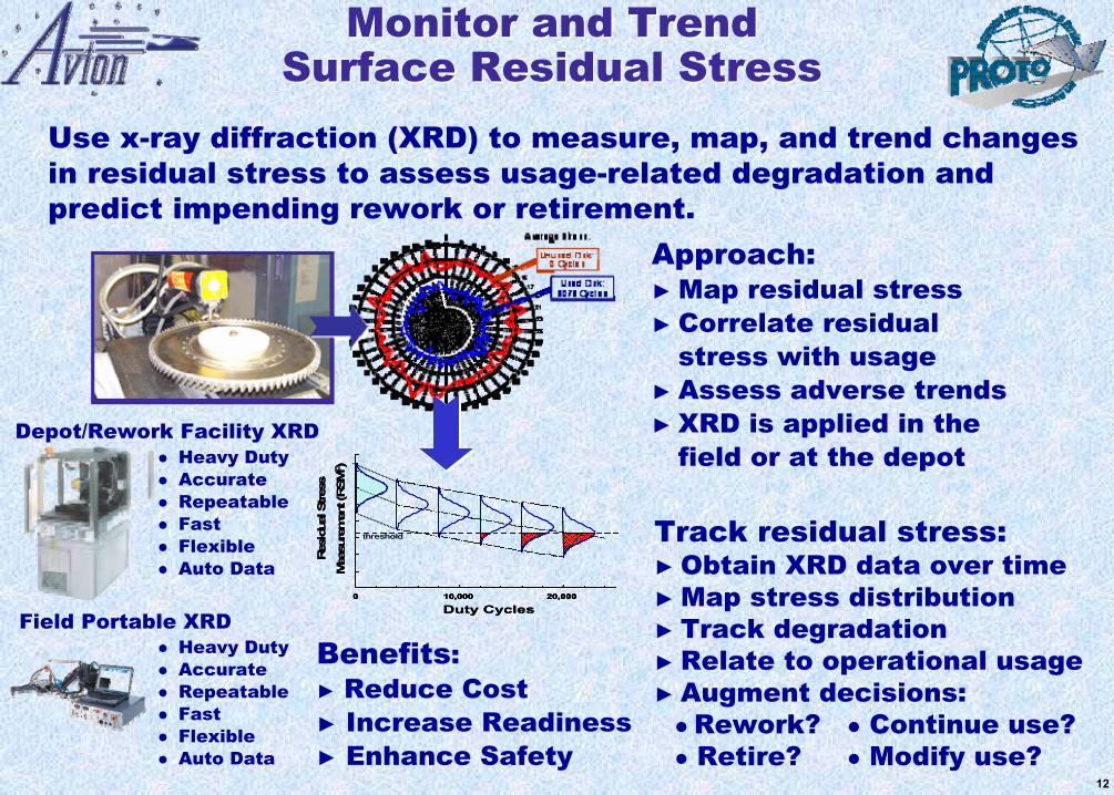
Approach:► Map residual stress ► Correlate residual
stress with usage► Assess adverse trends► XRD is applied in the
field or at the depot
Use x-ray diffraction (XRD) to measure, map, and trend changes in residual stress to assess usage-related degradation and predict impending rework or retirement.
Track residual stress:► Obtain XRD data over time► Map stress distribution► Track degradation► Relate to operational usage► Augment decisions:
Rework? Continue use?Retire? Modify use?
Benefits:► Reduce Cost► Increase Readiness► Enhance Safety
Monitor and Trend Surface Residual Stress
Monitor and Trend Surface Residual Stress
Duty Cycles
Res
idua
l Stres
s
Mea
sure
men
t (RSM
©)
0 10,000 20,000
threshold
Duty Cycles
Res
idua
l Stres
s
Mea
sure
men
t (RSM
©)
0 10,000 20,0000 10,000 20,0000 10,000 20,000
threshold
Depot/Rework Facility XRD
Field Portable XRD
Heavy DutyAccurateRepeatableFastFlexibleAuto Data
Heavy DutyAccurateRepeatableFastFlexibleAuto Data
12
TMTM
Inspect, Trend ComponentMaterial Condition
Inspect, Trend ComponentMaterial Condition
Benefits:► Map and track degradation. ► Correlate with usage.► Assess adverse trends.► Predict impending failures.► Predict remaining useful life.
► Induced Positron Annihilation (IPA) measures, maps, and trends component material condition at the lattice level.
► Monitor material degradation prior to crack initiation and assess continued safe usage, rework, or retirement.
Key Features:► High Sensitivity: Positrons probe
interstitial lattice sites.► Defects have more low
momentum free electrons. ► Atomic level impurity provides
unique signatures.► S-parameter quantifies
mechanically induced defects.► Damage quantified as compared
to material baseline.
IPA is being evaluated by AMRDEC and SOAR(A) on retired Chinook aft rotor shafts.
S = A/B
A
Peak Energy 511 keV
B
COUNTS
S = A/B
A
Peak Energy 511 keV
B
COUNTS
S = A/B
A
Peak Energy 511 keV
B
COUNTS
S = A/B
A
Peak Energy 511 keV
B
COUNTS
S = A/B
A
Peak Energy 511 keV
B
COUNTS
S = A/B
A
Peak Energy 511 keV
B
COUNTS
S-Parameter
105 lattice sites probed
β+
β+β+β+
β+
β+β+
e-
γ511 keV
γ 511 keV
β+
B+
Positron Emitter IPA-S Probe
105 lattice sites probed
β+
β+β+β+β+
β+β+
β+β+β+
e-
γ511 keV
γ 511 keV
β+
B+
Positron Emitter IPA-S Probe
13
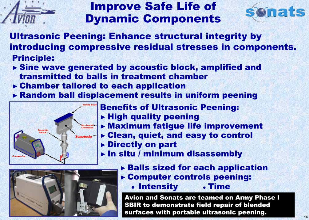
Ultrasonic Peening: Enhance structural integrity by introducing compressive residual stresses in components.
Benefits of Ultrasonic Peening: ►High quality peening ►Maximum fatigue life improvement ►Clean, quiet, and easy to control►Directly on part► In situ / minimum disassembly
Improve Safe Life ofDynamic ComponentsImprove Safe Life of
Dynamic Components
Principle:►Sine wave generated by acoustic block, amplified and
transmitted to balls in treatment chamber ►Chamber tailored to each application►Random ball displacement results in uniform peening
►Balls sized for each application►Computer controls peening:
● Intensity Time
Avion and Sonats are teamed on Army Phase I SBIR to demonstrate field repair of blended surfaces with portable ultrasonic peening.
14
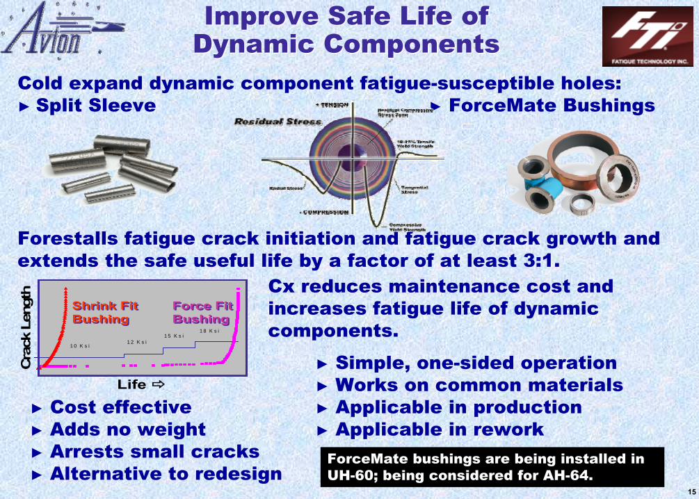
Cold expand dynamic component fatigue-susceptible holes: ► Split Sleeve ► ForceMate Bushings
Forestalls fatigue crack initiation and fatigue crack growth andextends the safe useful life by a factor of at least 3:1.
Cx reduces maintenance cost and increases fatigue life of dynamic components.
► Cost effective ► Adds no weight ► Arrests small cracks► Alternative to redesign
Improve Safe Life of Dynamic ComponentsImprove Safe Life of
Dynamic Components
► Simple, one-sided operation ► Works on common materials► Applicable in production► Applicable in rework
Cra
ck L
engt
h
Life
1 0 K s i1 2 K s i
1 5 K s i1 8 K s i
Shrink Fit BushingShrink Fit Bushing
Force Fit BushingForce Fit Bushing
Cra
ck L
engt
h
Life
1 0 K s i1 2 K s i
1 5 K s i1 8 K s i
Cra
ck L
engt
h
Life
1 0 K s i1 2 K s i
1 5 K s i1 8 K s i
Shrink Fit BushingShrink Fit Bushing
Force Fit BushingForce Fit Bushing
ForceMate bushings are being installed in UH-60; being considered for AH-64.
15
Structural Integrity LCMTechnologies are Available Structural Integrity LCM
Technologies are Available
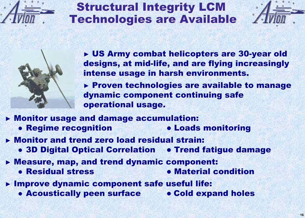
► US Army combat helicopters are 30-year old designs, at mid-life, and are flying increasingly intense usage in harsh environments.► Proven technologies are available to manage dynamic component continuing safe operational usage.
► Monitor usage and damage accumulation:Regime recognition Loads monitoring
► Monitor and trend zero load residual strain:3D Digital Optical Correlation Trend fatigue damage
► Measure, map, and trend dynamic component:Residual stress Material condition
► Improve dynamic component safe useful life:Acoustically peen surface Cold expand holes
16